EP4056446B1 - Schienenfahrzeug-kippsystem, kippsteuerverfahren und schienenfahrzeug - Google Patents
Schienenfahrzeug-kippsystem, kippsteuerverfahren und schienenfahrzeug Download PDFInfo
- Publication number
- EP4056446B1 EP4056446B1 EP21868042.9A EP21868042A EP4056446B1 EP 4056446 B1 EP4056446 B1 EP 4056446B1 EP 21868042 A EP21868042 A EP 21868042A EP 4056446 B1 EP4056446 B1 EP 4056446B1
- Authority
- EP
- European Patent Office
- Prior art keywords
- air spring
- height
- real
- value
- time
- Prior art date
- Legal status (The legal status is an assumption and is not a legal conclusion. Google has not performed a legal analysis and makes no representation as to the accuracy of the status listed.)
- Active
Links
Images

Classifications
-
- B—PERFORMING OPERATIONS; TRANSPORTING
- B61—RAILWAYS
- B61F—RAIL VEHICLE SUSPENSIONS, e.g. UNDERFRAMES, BOGIES OR ARRANGEMENTS OF WHEEL AXLES; RAIL VEHICLES FOR USE ON TRACKS OF DIFFERENT WIDTH; PREVENTING DERAILING OF RAIL VEHICLES; WHEEL GUARDS, OBSTRUCTION REMOVERS OR THE LIKE FOR RAIL VEHICLES
- B61F5/00—Constructional details of bogies; Connections between bogies and vehicle underframes; Arrangements or devices for adjusting or allowing self-adjustment of wheel axles or bogies when rounding curves
- B61F5/02—Arrangements permitting limited transverse relative movements between vehicle underframe or bolster and bogie; Connections between underframes and bogies
- B61F5/22—Guiding of the vehicle underframes with respect to the bogies
- B61F5/24—Means for damping or minimising the canting, skewing, pitching, or plunging movements of the underframes
- B61F5/245—Means for damping or minimising the canting, skewing, pitching, or plunging movements of the underframes by active damping, i.e. with means to vary the damping characteristics in accordance with track or vehicle induced reactions, especially in high speed mode
-
- B—PERFORMING OPERATIONS; TRANSPORTING
- B61—RAILWAYS
- B61F—RAIL VEHICLE SUSPENSIONS, e.g. UNDERFRAMES, BOGIES OR ARRANGEMENTS OF WHEEL AXLES; RAIL VEHICLES FOR USE ON TRACKS OF DIFFERENT WIDTH; PREVENTING DERAILING OF RAIL VEHICLES; WHEEL GUARDS, OBSTRUCTION REMOVERS OR THE LIKE FOR RAIL VEHICLES
- B61F5/00—Constructional details of bogies; Connections between bogies and vehicle underframes; Arrangements or devices for adjusting or allowing self-adjustment of wheel axles or bogies when rounding curves
- B61F5/02—Arrangements permitting limited transverse relative movements between vehicle underframe or bolster and bogie; Connections between underframes and bogies
- B61F5/04—Bolster supports or mountings
- B61F5/10—Bolster supports or mountings incorporating fluid springs
-
- B—PERFORMING OPERATIONS; TRANSPORTING
- B61—RAILWAYS
- B61L—GUIDING RAILWAY TRAFFIC; ENSURING THE SAFETY OF RAILWAY TRAFFIC
- B61L27/00—Central railway traffic control systems; Trackside control; Communication systems specially adapted therefor
- B61L27/04—Automatic systems, e.g. controlled by train; Change-over to manual control
Definitions
- the present application relates to the technical field of railway transportation, and in particular, to a tilting system and a tilting control method for railway vehicle and a railway vehicle.
- a centrifugal force generated when a railway vehicle is running on a curved road will make passengers feel uncomfortable and even cause an overturning accident in severe cases.
- JP 2008 100614 A discloses a device and a method for inclining a railroad vehicle body capable of enhancing the responsive speed of the railroad vehicle body inclination control, and enhancing the ride quality by realizing the smooth inclining operation and suppressing the vibration when the vehicle body is inclined.
- JP 5 513175 B2 discloses a vehicle body tilting device for a railway vehicle in which a pair of right and left air springs are arranged between a truck and a vehicle body, and the height of the air springs is controlled by the supply and exhaust of pressurized air into the air spring so that the vehicle body can be tilted.
- US 2015/353104 A1 discloses a track-guided vehicle is provided with a car body, and a bogie that supports the car body from the bottom, and has a frame capable of pivoting around an axis perpendicular to a track.
- the bogie is provided with: a car body tilting part that tilts the car body to the left and right in the direction of travel; a detection part that detects the amount of pivot of the frame; and a tilt control part that allows the car body to be tilted by the car body tilting part on the basis of the amount of pivot detected by the detection part.
- an outer rail is generally raised to a certain extent, so as to balance the centrifugal force by a centripetal component force (which also called as centripetal force) generated by the body weight of the vehicle.
- centripetal force which also called as centripetal force
- the body of a titling train can swing at a certain angle relative to the rail plane, which reduces the unbalanced centrifugal acceleration to a certain extent and improves the ride comfort.
- Traditional titling trains generally require a complex tilting system on a secondary suspension structure, resulting in low reliability and high cost.
- embodiments of the present application provide a tilting system and a tilting control method for railway vehicle, and a railway vehicle.
- a tilting system for a railway vehicle including a controller, a high-pressure air cylinder, a left air spring, a right air spring, a left auxiliary air chamber, a right auxiliary air chamber, a first three-position electromagnetic proportional flow valve, a second three-position electromagnetic proportional flow valve, sensors, a differential pressure valve and a two-position switching valve, where
- the sensors include an acceleration sensor and air spring height detection sensors, where
- the tilting system further includes a third three-position solenoid valve and a fourth three-position solenoid valve, where the third three-position solenoid valve communicates with the high-pressure air cylinder, the left air spring and the atmosphere, respectively; the fourth three-position solenoid valve communicates with the high-pressure air cylinder, the right air spring and the atmosphere, respectively; and the third three-position solenoid valve and the fourth three-position solenoid valve are controlled by the controller to open and close.
- the third three-position solenoid valve is a three-position electromagnetic switching valve or a three-position electromagnetic proportional flow valve; and/or the fourth three-position solenoid valve is a three-position electromagnetic switching valve or a three-position electromagnetic proportional flow valve.
- a tilting control method for a tilting system for railway vehicle including:
- the generating control instructions for the first three-position electromagnetic proportional flow valve and the second three-position electromagnetic proportional flow valve based on the real-time unbalanced centrifugal acceleration of the frame, the real-time height value of the left air spring and the real-time height value of the right air spring includes:
- the generating control instructions for the first three-position electromagnetic proportional flow valve and the second three-position electromagnetic proportional flow valve based on the real-time unbalanced centrifugal acceleration of the frame, the real-time height value of the left air spring and the real-time height value of the right air spring includes:
- the method further includes:
- the method further includes:
- railway vehicle including: the tilting system for railway vehicle described in the present application.
- the height difference of the left and right air springs can be adjusted based on the driving state of the railway vehicle, thereby the tilting angle is adjusted, which is beneficial to balance centrifugal force generated by the railway vehicle when running on curved road sections.
- FIG. 1 is a schematic structural diagram of a tilting system for railway vehicle according to the present application.
- the tilting system for railway vehicle according to an embodiment of the present application includes: a controller 101, a high-pressure air cylinder 102, an air compressor (which is not shown in FIG. 1 ), air springs, three-position electromagnetic proportional flow valves, sensors, a differential pressure valve 104, auxiliary air chambers, and a two-position switching valve 111.
- the air springs include a left air spring 105 and a right air spring 107; the auxiliary air chambers include a left auxiliary air chamber 106 and a right auxiliary air chamber 108; and the three-position electromagnetic proportional flow valves include a first three-position electromagnetic proportional flow valve 109 and a second three-position electromagnetic proportional flow valve 110.
- the air compressor is configured to provide high-pressure air to the high-pressure air cylinder 102 and the high-pressure air cylinder 102 is configured to charge the high-pressure air into the left air spring 105 through the first three-position electromagnetic proportional flow valve 109 and charge the high-pressure air into the right air spring 107 through the second three-position electromagnetic proportional flow valve 110.
- the left air spring 105 discharges air therein to atmosphere through the first three-position electromagnetic proportional flow valve 109 and the right air spring 107 discharges air therein to atmosphere through the second three-position electromagnetic proportional flow valve 110; the left air spring 105 communicates with the left auxiliary air chamber 106 and the right air spring 107 communicates with the right auxiliary air chamber 108.
- the differential pressure valve 104 is configured to communicate with the left auxiliary air chamber 106 and the right auxiliary air chamber 108 to perform pressure balance of air inside the left auxiliary air chamber 106 and the right auxiliary air chamber 108 as desired; and the two-position switching valve 111 communicates with the left auxiliary air chamber 106 and the right auxiliary air chamber 108 through pipelines, respectively.
- the sensors are configured to collect data of the railway vehicle while driving and transmit the collected data to the controller 101; the controller 101 is configured to control the first three-position electromagnetic proportional flow valve 109 and the second three-position electromagnetic proportional flow valve 110 based on the data collected by the sensors.
- the right air spring 107 is mounted under a right side of the body of the railway vehicle.
- the right air spring 107 communicates with the right auxiliary air chamber 108 and air can flow between the right auxiliary air chamber 108 and the right air spring 107.
- left air springs 105 There are a plurality of the left air springs 105 and a plurality of the right air springs 107.
- the first three-position electromagnetic proportional flow valve 109 has three air inlet-outlets among which a first air inlet-outlet communicates with the high-pressure air cylinder 102, a second air inlet-outlet communicates with the atmosphere through a discharge pipe and a third air inlet-outlet communicates with the left air spring 105 through a pipeline.
- the first air inlet-outlet communicates with the third air inlet-outlet under the control of the controller 101, and since the air pressure in the high-pressure air cylinder 102 is higher, the air can flow from the high-pressure air cylinder 102 to the left air spring 105 to charge air into the left air spring 105.
- the number of the first three-position electromagnetic proportional flow valves 109 corresponds to the number of the left air springs 105 and the number of the second three-position electromagnetic proportional flow valves 110 corresponds to the number of the right air springs 107.
- FIG. 2 is a schematic diagram showing installation of the acceleration sensor. As shown in FIG. 2 , the acceleration sensor is mounted on a side beam of the frame of the railway vehicle and the acceleration sensor is configured to detect the unbalanced centrifugal acceleration of the frame.
- the air spring height detection sensors are configured to detect the heights of air springs. Since the height of each air spring may be different, a height detection sensor needs to be provided for each air spring. As a preferred implementation, a noncontact angle sensor is used as the air spring height detection sensor to reduce wear and improve reliability.
- the differential pressure valve 104 communicates with the left auxiliary air chamber 106 and the right auxiliary air chamber 108 through pipelines, respectively.
- the differential pressure valve 104 as a safety component of the entire system, has an opening pressure set to a higher value (e.g., 250 ⁇ 20 kPa).
- the differential pressure valve 104 Under normal circumstances, even when the railway vehicle is in the maximum tilting state, the differential pressure valve 104 is still in the closed state; while in a fault state, if an air spring at a side is completely out of air, the pressure difference between the left and right air springs reaches the opening threshold of the differential pressure valve 104, and the differential pressure valve 104 is automatically opened, which reduces the height difference of the left and right air springs and thus ensures the safe operation of the railway vehicle.
- the differential pressure valve 104 as a safety component of the entire system, will only be opened under the most unfavorable fault conditions to urgently balance the air pressure difference between the left auxiliary air chamber 106 and the right auxiliary air chamber 108.
- the two-position switching valve 111 as a conventional component, is closed when the railway vehicle enters a section with an easement curve and/or a section with a circular curve (when the railway vehicle runs on the curved road section, the section is changed as follows: straight line - entering an easement curve - circle curve - exiting the easement curve - straight line) so that airbags on both sides maintain the height difference, and the two-position switching valve 111 is opened when the railway vehicle exits the section with the easement curve such that the airbags on both sides restore to the same height.
- the two-position switching valve 111 is also closed.
- the height difference between the left air spring 105 and the right air spring 107 can be adjusted based on the driving state of the railway vehicle, thereby the tilting angle is adjusted, which is beneficial to balance centrifugal force generated by the railway vehicle when running on curved road sections.
- FIG. 3 is a schematic diagram of a tilting system for railway vehicle according to another embodiment of the present application.
- the tilting system for railway vehicle according to another embodiment of the present application further includes: a third three-position solenoid valve 112 and a fourth three-position solenoid valve 113, wherein
- the third three-position solenoid valve 112 communicates with the high-pressure air cylinder 102, the left air spring 105 and the atmosphere, respectively;
- the fourth three-position solenoid valve 113 communicates with the high-pressure air cylinder 102, the right air spring 107 and the atmosphere, respectively; and the third three-position solenoid valve 112 and the fourth three-position solenoid valve 113 are controlled by the controller 101 to open and close.
- the third three-position solenoid valve 112 and the fourth three-position solenoid valve 113 are additionally provided for the tilting system for railway vehicle.
- the third three-position solenoid valve 112 is connected in parallel to the first three-position electromagnetic proportional flow valve 109, and can speed up the charging air speed or discharging air speed of the left air spring 105 by cooperating with the first three-position electromagnetic proportional flow valve 109.
- the fourth three-position solenoid valve 113 is connected in parallel to the second three-position electromagnetic proportional flow valve 110, and can speed up the charging air speed or discharging air speed of the right air spring 107 by cooperating with the second three-position electromagnetic proportional flow valve 110.
- Each of the third three-position solenoid valve 112 and the fourth three-position solenoid valve 113 can be a three-position electromagnetic switching valve, or a three-position electromagnetic proportional flow valve. It can be selected according to actual needs.
- the tilting system for railway vehicle can speed up the charging air speed or discharging air speed of the air spring, which is beneficial to quickly adjust the state of the railway vehicle and reduce the impact of centrifugal force on passenger comfort.
- FIG. 4 is a flow chart of a tilting control method according to an embodiment of the present application. As shown in FIG. 4 , the tilting control method according to an embodiment of the present application includes the following steps.
- Step 401 receiving, by the controller 101, a real-time unbalanced centrifugal acceleration of a frame, and comparing the real-time unbalanced centrifugal acceleration of the frame with a preset unbalanced centrifugal acceleration threshold.
- the real-time unbalanced centrifugal acceleration of the frame is collected by an acceleration sensor disposed on the side beam of the frame of the railway vehicle and transmitted to the controller 101 by the acceleration sensor.
- the unbalanced centrifugal acceleration threshold represents a maximum unbalanced centrifugal acceleration allowed for the railway vehicle.
- the real-time unbalanced centrifugal acceleration of the frame is less than the unbalanced centrifugal acceleration threshold, it is considered that the railway vehicle is running on a straight line road or a curve road with sufficient superelevation, and the system enters a height adjustment mode.
- the real-time unbalanced centrifugal acceleration of the frame is greater than or equal to the unbalanced centrifugal acceleration threshold, it is considered that the centrifugal acceleration of the railway vehicle needs to be balanced, and the system enters an active tilting mode. In the embodiment of the present application, the implementation process of the active tilting mode will be further described.
- Step 402 generating, when the real-time unbalanced centrifugal acceleration of the frame is greater than the preset unbalanced centrifugal acceleration threshold, control instructions for the first three-position electromagnetic proportional flow valve 109 and the second three-position electromagnetic proportional flow valve 110 based on the real-time unbalanced centrifugal acceleration of the frame, a real-time height value of the left air spring 105 and a real-time height value of the right air spring 107 to perform an operation of charging air or discharging air on the left air spring 105 and the right air spring 107 such that a tilting operation is completed.
- the railway vehicle When the real-time unbalanced centrifugal acceleration of the frame is greater than a preset unbalanced centrifugal acceleration threshold, the railway vehicle enters an active tilting mode.
- control instructions for the first three-position electromagnetic proportional flow valve 109 and the second three-position electromagnetic proportional flow valve 110 are generated based on the real-time unbalanced centrifugal acceleration of the frame, a real-time height value of the left air spring 105 and a real-time height value of the right air spring 107 to perform the operation of charging air or discharging air on the left air spring 105 and the right air spring 107 such that a tilting operation is completed.
- the specific generation process of the control instructions will be further described.
- the height difference between the left air spring 105 and the right air spring 107 can be adjusted based on the driving state of the railway vehicle, thereby the tilting angle is adjusted, which is beneficial to balance centrifugal force generated by the railway vehicle when running on curved road sections.
- the generating control instructions for the first three-position electromagnetic proportional flow valve 109 and the second three-position electromagnetic proportional flow valve 110 based on the real-time unbalanced centrifugal acceleration of the frame, a real-time height value of the left air spring 105 and a real-time height value of the right air spring 107 includes:
- ⁇ ref is the tilting angle of the body of the railway vehicle
- ⁇ nc is the real-time unbalanced centrifugal acceleration of the frame
- ⁇ nc0 is an allowable maximum unbalanced centrifugal acceleration, which is a preset value
- g is the gravitational acceleration.
- ⁇ z represents the target value of the height difference between the left air spring 105 and the right air spring 107; and 2b is a lateral span between the left air spring 105 and the right air spring 107, which is an actual measurable value.
- the target value of a height difference between the left air spring 105 and the right air spring 107 can be further decomposed into a height change target value of the left air spring 105 and a height change target value of the right air spring 107.
- ⁇ z ⁇ z L + ⁇ z R .
- ⁇ z L represents the raised height target value of the left air spring 105
- ⁇ z R represents the lowered height target value of the right air spring 107.
- ⁇ z R,max represents a maximum allowable lowering height of the right air spring 107, which is a preset value.
- ⁇ z L,max represents a maximum allowable raising height of the left air spring 105, which is a preset value.
- the height change target values of the left air spring 105 and the right air spring 107 can be differentiated to obtain the height change speed value.
- the tilting angle of the body of the railway vehicle is calculated based on the real-time unbalanced centrifugal acceleration of the frame of the railway vehicle, and then the height change target value and the height change speed value of the air springs are calculated, and finally control instructions for the three-position electromagnetic proportional flow valves are generated, which is beneficial to precisely control the tilting of the railway vehicle and balance the centrifugal force generated by the railway vehicle when it runs on curved road sections.
- the generating control instructions for the first three-position electromagnetic proportional flow valve 109 and the second three-position electromagnetic proportional flow valve 110 based on the real-time unbalanced centrifugal acceleration of the frame, a real-time height value of the left air spring 105 and a real-time height value of the right air spring 107 includes:
- the process of generating the control instructions for the electromagnetic proportional flow valves can be performed by combining the feedforward control amounts and the feedback control amounts.
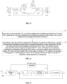
- FIG. 5 is a schematic diagram showing a control mode of a combination of feedforward control and feedback control in a tilting control method for railway vehicle according to an embodiment of the present application.
- a rate of change a nc ′ of the real-time unbalanced centrifugal acceleration of the frame is calculated based on the real-time unbalanced centrifugal acceleration a nc of the frame.
- a feedforward controller obtains a feedforward control amount s ff of the left (right) air spring by, for instance, multiplying the rate of change a nc ′ of the real-time unbalanced centrifugal acceleration of the frame by an experimentally measured proportional coefficient based on the rate of change a nc ′ of the real-time unbalanced centrifugal acceleration of the frame, and compares the actual height values z f of the left (right) air spring with height target values z ref of the left (right) air spring (which can be obtained by the height change target value and the height reference value of the air spring).
- the threshold e.g., obtained by using the PID algorithm
- the operation of charging air or discharging air on the left (right) air spring is controlled based on the control amount s until the difference between the actual height value of the left (right) air spring and the height target value of the left (right) air spring is within the preset interval range, thereby the tilting action of the railway vehicle is realized.
- the feedforward control is a predictive control method, which can compensate a control signal at the next moment based on a change trend of the observed amount, so that the actual control signal is closer to the ideal value.
- feedforward control and feedback control are combined, thereby generating control instructions for electromagnetic proportional flow valves. It is beneficial to improve the speed of responsiveness.
- the method further includes: when the railway vehicle exits a curve road section, balancing the left air spring 105 and the right air spring 107.
- the real-time unbalanced centrifugal acceleration of the frame gradually decreases, and the outer air spring begins to discharge air and the height of the outer air spring is lowered.
- the two-position control switching valve is opened, so that the air inside the outer air spring flows into the inner air spring, and the left and right air springs return to a balanced state.
- the outer air spring described in the embodiment of the present application is an air spring with a relatively higher height of the left air spring 105 and the right air spring 107
- the inner air spring is an air spring with a relatively lower height of the left air spring 105 and the right air spring 107.
- the height deviation value of the air spring is a difference between the real-time height value of the left and right air springs and the target height value of the left and right air springs.
- the height deviation value of the left air spring is a difference between the real-time height value of the left air spring and the target height value of the left air spring
- the height deviation value of the right air spring is a difference between the real-time height value of the right air spring and the target height value of the right air spring.
- the height difference between the left air spring 105 and the right air spring 107 can be adjusted based on the driving state of the railway vehicle, thereby the tilting angle is adjusted, which is beneficial to balance centrifugal force generated by the railway vehicle when running on curved road sections.
- the method further includes:
- the railway vehicle when the real-time unbalanced centrifugal acceleration of the frame is less than or equal to the preset unbalanced centrifugal acceleration threshold, the railway vehicle enters a height-adjusting mode.
- the real-time height value of the left air spring 105 can be obtained through a height detection sensor provided for the left air spring 105 and the real-time height of the right air spring 107 can be obtained through a height detection sensor provided for the right air spring 107.
- the controller 101 After obtaining the real-time height value of the left air spring 105 and the real-time height value of the right air spring 107 from the corresponding sensors, the controller 101 compares the real-time height value of the left air spring 105 with a preset first height target value to obtain a first height deviation value of the left air spring 105, and compares the real-time height value of the right air spring 107 with a preset second height target value to obtain a second height deviation value of the right air spring 107.
- the first height target value and the second height target value are set according to actual needs, and they may be the same or different.
- the left air spring 105 it is first determined that whether the first height deviation value is within the preset first interval. When the first height deviation value is within the first interval, it means that the first height deviation value of the left air spring 105 is within the allowable range and thus the height of the left air spring 105 does not need to be adjusted. When the first height deviation value is outside the first interval, the height of the left air spring 105 needs to be adjusted. During adjustment, whether the height of the left air spring 105 should be rasised or lowered is determined based on whether the first height deviation value is positive or negative.
- a control instruction is generated for the first three-position electromagnetic proportional flow valve 109, and the left air spring 105 is charged air through the first three-position electromagnetic proportional flow valve 109; and when the height of the left air spring 105 needs to be lowered, a control instruction is generated for the first three-position electromagnetic proportional flow valve 109, and the left air spring 105 is discharged air through the first three-position electromagnetic proportional flow valve 109.
- the real-time height value of the left air spring 105 is continuously measured, and when the first height deviation value is within the preset first interval, the operation of charging air or discharging air on the left air spring 105 is stopped.
- the operation on the right air spring 107 is similar to the operation on the left air spring 105 described above.
- first interval range and the second interval range may be the same or different, which is specifically determined based on the actual situation.
- the height of the air springs are adjusted so as to adjust the state of the railway vehicle and reduce the effect of centrifugal force on passenger comfort.
- a railway vehicle including: the tilting system for a railway vehicle, is provided.
- the height difference between the left air spring and the right air spring can be adjusted based on the driving state of the railway vehicle, thereby the tilting angle is adjusted, which is beneficial to balance centrifugal force generated by the railway vehicle when running on curved road sections.
- the device embodiments described above are merely illustrative, where the units described as separate components may or may not be physically separate, and the components displayed as units may or may not be physical units, that is, may be located at the same place or be distributed to multiple network units. Some or all of the modules may be selected according to actual needs to achieve the objectives of the solutions of the present embodiment. Those of ordinary skill in the art can understand and implement the embodiments described above without paying creative labors.
Landscapes
- Engineering & Computer Science (AREA)
- Mechanical Engineering (AREA)
- Vehicle Body Suspensions (AREA)
Claims (9)
- Neigesystem für Schienenfahrzeuge umfassend eine Steuerung (101), einen Hochdruck-Luftzylinder (102), eine linke Luftfeder (105), eine rechte Luftfeder (107), eine linke Hilfsluftkammer (106), eine rechte Hilfsluftkammer (108), ein erstes elektromagnetisches Dreistellungs-Proportionaldurchflussventil (109), ein zweitee elektromagnetisches Dreistellungs-Proportionaldurchflussventil (110), Sensoren, ein Differenzdruckventil (104) und ein Zweistellungs-Schaltventil (111), wobeidie linke Luftfeder (105) mit der linken Hilfsluftkammer (106) und die rechte Luftfeder (107) mit der rechten Hilfsluftkammer (108) in Verbindung steht;die Sensoren einen Beschleunigungssensor und einen Höhendetektionssensor, der für die linke Luftfeder (105) vorgesehen ist, und einen Höhendetektionssensor, der für die rechte Luftfeder (107) vorgesehen ist, aufweisen, wobei der Beschleunigungssensor an einem Seitenträger eines Rahmens des Schienenfahrzeugs angebracht und so konfiguriert ist, dass er eine unsymmetrische Zentrifugalbeschleunigung des Rahmens detektiert; und die gesammelten Daten an die Steuerung (101) überträgt;der Höhendetektionssensor, der für die linke Luftfeder (105) vorgesehen ist, und der Höhendetektionssensor, der für die rechte Luftfeder (107) vorgesehen ist, an benachbarten Positionen der linken Luftfeder (105) und der rechten Luftfeder (107) angebracht und so konfiguriert sind, dass sie einen Echtzeit-Höhenwert der linken Luftfeder (105) und einen Echtzeit-Höhenwert der rechten Luftfeder (107) erfassen;die Steuerung (101) so konfiguriert ist, dass sie das erste elektromagnetische Dreistellungs-Proportionaldurchflussventil (109) und das zweite elektromagnetische Dreistellungs-Proportionaldurchflussventil (110) auf Basis der Echtzeit-Ungleichgewichtszentrifugalbeschleunigung des Rahmens, dem Echtzeit-Höhenwert der linken Luftfeder (105) und dem Echtzeit-Höhenwert der rechten Luftfeder (107) steuert, so dass Hochdruckluft in dem Hochdruck-Luftzylinder (102) in die linke Luftfeder (105) durch das erste elektromagnetische Dreistellungs-Proportionaldurchflussventil (109) und in die rechte Luftfeder (107) durch das zweite elektromagnetische Dreistellungs-Proportionaldurchflussventil (110) geladen wird, oder Luft im Inneren der linken Luftfeder (105) durch das erste elektromagnetische Dreistellungs-Proportionaldurchflussventil (109) in die Atmosphäre abgelassen wird und Luft im Inneren der rechten Luftfeder (107) durch das zweite elektromagnetische Dreistellungs-Proportionaldurchflussventil (110) in die Atmosphäre abgelassen wird; unddas Differenzdruckventil (104) so konfiguriert ist, dass es mit der linken Hilfsluftkammer (106) und der rechten Hilfsluftkammer (108) in Verbindung steht; beziehungsweise das Zweistellungs-Schaltventil (111) mit der linken Hilfsluftkammer (106) beziehungsweise der rechten Hilfsluftkammer (108) über Rohrleitungen in Verbindung steht.
- Neigesystem gemäß Anspruch 1, weiterhin umfassend ein drittes Dreistellungs-Magnetventil (112) und ein viertes Dreistellungs-Magnetventil (113), wobei
das dritte Dreistellungs-Magnetventil (112) mit dem Hochdruck-Luftzylinder (102), der linken Luftfeder (105) beziehungsweise der Atmosphäre in Verbindung steht; das vierte Dreistellungs-Magnetventil (113) mit dem Hochdruck-Luftzylinder (102) und der rechten Luftfeder (107) beziehungsweise der Atmosphäre in Verbindung steht; und das dritte Dreistellungs-Magnetventil (112) und das vierte Dreistellungs-Magnetventil (113) von der Steuerung (101) zum Öffnen und Schließen gesteuert werden. - Neigesystem gemäß Anspruch 2, wobei das dritte Dreistellungs-Magnetventil (112) ein elektromagnetisches Dreistellungs-Schaltventil oder ein elektromagnetisches Dreistellungs-Proportionaldurchflussventil ist; und/oder
das vierte Dreistellungs-Magnetventil (113) ein elektromagnetisches Dreistellungsschaltventil oder ein elektromagnetisches Dreistellungsproportionalventil ist. - Neigesteuerungsverfahren für ein Neigesystem für ein Schienenfahrzeug gemäß einem der Ansprüche 1 bis 3, umfassend:Schritt S11, Empfangen einer vom Beschleunigungssensor erfassten unsymmetrischen Echtzeit-Zentrifugalbeschleunigung eines Rahmens durch die Steuerung (101) und Vergleichen der unsymmetrischen Echtzeit-Zentrifugalbeschleunigung des Rahmens mit einem voreingestellten Schwellenwert für unsymmetrische Zentrifugalbeschleunigung; undSchritt S12, wenn die unsymmetrische Zentrifugalbeschleunigung des Rahmens in Echtzeit größer ist als der voreingestellte Schwellenwert für die unsymmetrische Zentrifugalbeschleunigung, Erzeugen von Steuerungsanweisungen für das erste elektromagnetische Dreistellungs-Proportionaldurchflussventil (109) und das zweite elektromagnetische Dreistellungs-Proportionaldurchflussventil (110) basierend auf der unsymmetrischen Zentrifugalbeschleunigung des Rahmens in Echtzeit, einem Echtzeit-Höhenwert der linken Luftfeder (105) und einem Echtzeit-Höhenwert der rechten Luftfeder (107), um einen Vorgang des Aufladens von Luft oder des Ablassens von Luft an der linken Luftfeder (105) und der rechten Luftfeder (107) durchzuführen, so dass ein Neigevorgang abgeschlossen wird.
- Neigesteuerungsverfahren gemäß Anspruch 4, wobei das Erzeugen von Steuerungsanweisungen für das erste elektromagnetische Dreistellungs-Proportionaldurchflussventil (109) und das zweite elektromagnetische Dreistellungs-Proportionaldurchflussventil (110) auf Basis der unsymmetrischen Echtzeit-Zentrifugalbeschleunigung des Rahmens, des Echtzeit-Höhenwerts der linken Luftfeder (105) und des Echtzeit-Höhenwerts der rechten Luftfeder (107) Folgendes umfasst:Berechnen eines Neigungswinkels eines Wagenkastens des Schienenfahrzeugs basierend auf der in Echtzeit ermittelten unsymmetrischen Zentrifugalbeschleunigung des Rahmens;Berechnen eines Sollwertes einer Höhendifferenz zwischen der linken Luftfeder (105) und der rechten Luftfeder (107) auf Basis des Neigungswinkels des Wagenkastens des Schienenfahrzeugs;Berechnen eines Höhenänderungs-Zielwertes der linken Luftfeder (105), eines Höhenänderungs-Zielwertes der rechten Luftfeder (107) und eines Höhenänderungs-Geschwindigkeitswertes der linken Luftfeder (105) und eines Höhenänderungs-Geschwindigkeitswertes der rechten Luftfeder (107) basierend auf dem Zielwert einer Höhendifferenz zwischen der linken Luftfeder (105) und der rechten Luftfeder (107); undErzeugen von Steuerungsanweisungen für das erste elektromagnetische Dreistellungs-Proportionaldurchflussventil (109) und das zweite elektromagnetische Dreistellungs-Proportionaldurchflussventil (110) auf Basis des empfangenen Echtzeit-Höhenwerts der linken Luftfeder (105) und des Echtzeit-Höhenwerts der rechten Luftfeder (107) in Kombination mit dem Höhenänderungs-Zielwert der linken Luftfeder (105), dem Höhenänderungs-Zielwert der rechten Luftfeder (107), dem Höhenänderungs-Geschwindigkeitswert der linken Luftfeder (105) und dem Höhenänderungs-Geschwindigkeitswert der rechten Luftfeder (107).
- Neigesteuerungsverfahren gemäß Anspruch 4, wobei das Erzeugen von Steueranweisungen für das erste elektromagnetische Dreistellungs-Proportionaldurchflussventil (109) und das zweite elektromagnetische Dreistellungs-Proportionaldurchflussventil (110) auf Basis der unsymmetrischen Echtzeit-Zentrifugalbeschleunigung des Rahmens, des Echtzeit-Höhenwerts der linken Luftfeder (105) und des Echtzeit-Höhenwerts der rechten Luftfeder (107) Folgendes umfasst:Berechnen einer Änderungsquote der unsymmetrischen Echtzeit-Zentrifugalbeschleunigung des Rahmens basierend auf der unsymmetrischen Echtzeit-Zentrifugalbeschleunigung des Rahmens; und Erhalten eines Vorwärtssteuerungswertes der linken Luftfeder (105) und eines Vorwärtssteuerungswertes der rechten Luftfeder (107) auf Basis der Änderungquote der unsymmetrischen Echtzeit-Zentrifugalbeschleunigung des Rahmens ;Berechnen eines Höhensollwertes der linken Luftfeder (105) und eines Höhensollwertes der rechten Luftfeder (107) basierend auf der unsymmetrischen Echtzeit-Zentrifugalbeschleunigung des Rahmens;Bestimmen eines Rückkopplungssteuerwerts der linken Luftfeder (105) auf Basis des Echtzeit-Höhenwerts der linken Luftfeder (105) und des Höhensollwerts der linken Luftfeder (105); und Bestimmen eines Rückkopplungssteuerungswerts der rechten Luftfeder (107) auf Basis des Echtzeit-Höhenwerts der rechten Luftfeder (107) und des Höhensollwerts der rechten Luftfeder (107); undErzeugen der Steuerungsanweisung für das erste elektromagnetische Dreistellungs-Proportionaldurchflussventil (109) auf Basis des Rückkopplungssteuerungswerts der linken Luftfeder (105) und des Vorwärtssteuerungswerts der linken Luftfeder (105); und Erzeugen der Steuerungsanweisung für das zweite elektromagnetische Dreistellungs-Proportionaldurchflussventil (110) auf Basis des Rückkopplungssteuerungswerts der rechten Luftfeder (107) und des Vorwärtssteuerungswerts der rechten Luftfeder (107).
- Neigesteuerungsverfahren gemäß Anspruch 4 weiterhin umfassend:wenn das Schienenfahrzeug einen kurvenreichen Straßenabschnitt verlässt, einen Ausgleich der linken Luftfeder (105) und der rechten Luftfeder (107), wobeiwenn das Schienenfahrzeug einen leicht kurvenreichen Straßenabschnitt verlässt, die unsymmetrische Echtzeit-Zentrifugalbeschleunigung des Rahmens allmählich abnimmt, und eine äußere Luftfeder beginnt, Luft auszustoßen, und eine Höhe der äußeren Luftfeder abgesenkt wird; wenn ein Höhenabweichungswert der linken Luftfeder (105) gleich einem Höhenabweichungswert der rechten Luftfeder (107) ist, das Zwei-Positionen-Steuerungsschaltventil geöffnet wird, um zu ermöglichen, dass Luft innerhalb einer äußeren Luftfeder in eine innere Luftfeder fließt, so dass die linke Luftfeder (105) und die rechte Luftfeder (107) in einen ausgeglichenen Zustand zurückkehren; wobeidie äußere Luftfeder eine Luftfeder mit einer relativ größeren Höhe im Vergleich zu der linken Luftfeder (105) und der rechten Luftfeder (107) ist, und die innere Luftfeder eine Luftfeder mit einer relativ geringeren Höhe der linken Luftfeder (105) und der rechten Luftfeder (107) ist, und der Höhenabweichungswert der Luftfeder eine Differenz zwischen dem Echtzeit-Höhenwert der Luftfeder und dem Zielhöhenwert der Luftfeder ist.
- Neigesteuerungsverfahren gemäß Anspruch 4 weiterhin umfassend:Schritt S21, wenn die unausgeglichene Echtzeit-Zentrifugalbeschleunigung des Rahmens kleiner oder gleich dem voreingestellten Schwellenwert der unsymmetrischen Zentrifugalbeschleunigung ist, Empfangen des Echtzeit-Höhenwerts der linken Luftfeder (105) und des Echtzeit-Höhenwerts der rechten Luftfeder (107) durch die Steuerung 101 und Berechnen eines ersten Höhenabweichungswerts auf der Basis des Echtzeit-Höhenwerts der linken Luftfeder (105) und eines zweiten Höhenabweichungswerts auf der Basis des Echtzeit-Höhenwerts der rechten Luftfeder (107); undSchritt S22, Vergleichen des ersten Höhenabweichungswertes mit einem voreingestellten ersten Intervall, und wenn der erste Höhenabweichungswert außerhalb des ersten Intervalls liegt, Einstellen der Höhe der linken Luftfeder (105) durch Steuern des ersten elektromagnetischen Dreistellungs-Proportionaldurchflussventils (109); und Vergleichen des zweiten Höhenabweichungswertes mit einem voreingestellten zweiten Intervall, und wenn der zweite Höhenabweichungswert außerhalb des zweiten Intervalls liegt, Einstellen der Höhe der rechten Luftfeder (107) durch Steuern des zweiten elektromagnetischen Dreistellungs-Proportionaldurchflussventils (110).
- Schienenfahrzeug, umfassend:
das Neigesystem für Schienenfahrzeuge gemäß einem der Ansprüche 1 bis 3.
Applications Claiming Priority (2)
| Application Number | Priority Date | Filing Date | Title |
|---|---|---|---|
| CN202010990343.2A CN112046533B (zh) | 2020-09-18 | 2020-09-18 | 轨道车辆倾摆系统、倾摆控制方法及轨道车辆 |
| PCT/CN2021/077341 WO2022057202A1 (zh) | 2020-09-18 | 2021-02-23 | 轨道车辆倾摆系统、倾摆控制方法及轨道车辆 |
Publications (3)
| Publication Number | Publication Date |
|---|---|
| EP4056446A1 EP4056446A1 (de) | 2022-09-14 |
| EP4056446A4 EP4056446A4 (de) | 2023-07-12 |
| EP4056446B1 true EP4056446B1 (de) | 2025-04-02 |
Family
ID=73603427
Family Applications (1)
| Application Number | Title | Priority Date | Filing Date |
|---|---|---|---|
| EP21868042.9A Active EP4056446B1 (de) | 2020-09-18 | 2021-02-23 | Schienenfahrzeug-kippsystem, kippsteuerverfahren und schienenfahrzeug |
Country Status (6)
| Country | Link |
|---|---|
| US (1) | US12479480B2 (de) |
| EP (1) | EP4056446B1 (de) |
| JP (1) | JP7434551B2 (de) |
| CN (1) | CN112046533B (de) |
| ES (1) | ES3030989T3 (de) |
| WO (1) | WO2022057202A1 (de) |
Families Citing this family (14)
| Publication number | Priority date | Publication date | Assignee | Title |
|---|---|---|---|---|
| CN112046533B (zh) * | 2020-09-18 | 2021-11-30 | 中车青岛四方机车车辆股份有限公司 | 轨道车辆倾摆系统、倾摆控制方法及轨道车辆 |
| CN112810651B (zh) * | 2021-01-14 | 2022-05-31 | 中车长春轨道客车股份有限公司 | 一种轨道车辆抗侧滚装置的控制方法 |
| CN112793610B (zh) * | 2021-01-30 | 2022-08-16 | 上海工程技术大学 | 一种地铁列车坡道行驶防倾斜稳定系统 |
| CN116194310A (zh) * | 2021-09-28 | 2023-05-30 | 华为技术有限公司 | 电磁阀总成、空气悬架系统、车辆、控制方法及相关设备 |
| CN114771594B (zh) * | 2022-04-29 | 2024-03-12 | 株洲时代新材料科技股份有限公司 | 一种轨道车辆小幅倾摆调节系统及其控制方法 |
| CN114802332B (zh) * | 2022-04-29 | 2024-05-07 | 株洲时代新材料科技股份有限公司 | 一种提高轨道车辆曲线行驶速度的方法及小幅倾摆系统 |
| CN114771595B (zh) * | 2022-04-29 | 2024-03-12 | 株洲时代新材料科技股份有限公司 | 一种轨道车辆小幅倾摆快速调节系统及其控制方法 |
| CN115195801B (zh) * | 2022-08-11 | 2023-12-26 | 中车青岛四方机车车辆股份有限公司 | 转向架主动径向系统、控制方法、转向架及轨道车辆 |
| CN115817555A (zh) * | 2022-12-08 | 2023-03-21 | 中车青岛四方机车车辆股份有限公司 | 轨道车辆转向架空气弹簧高度实时控制方法及系统 |
| CN116424394A (zh) * | 2023-03-21 | 2023-07-14 | 中车青岛四方机车车辆股份有限公司 | 一种列车防倾覆的方法、系统、装置及存储介质 |
| CN118289051B (zh) * | 2024-06-05 | 2024-10-11 | 比亚迪股份有限公司 | 轨道车辆及控制方法、电子设备和存储介质 |
| DE102024118803A1 (de) * | 2024-07-02 | 2026-01-08 | Knorr-Bremse Systeme für Schienenfahrzeuge GmbH | Niveauregulierung für Schienenfahrzeug |
| CN119748432B (zh) * | 2024-12-10 | 2025-10-21 | 中能兴盛(香河)半导体精密制造有限公司 | 一种电力巡检机器人软体腰部平台的平衡控制方法 |
| CN120135235B (zh) * | 2025-04-03 | 2025-07-25 | 西南交通大学 | 一种列车空气弹簧主动倾摆系统 |
Family Cites Families (30)
| Publication number | Priority date | Publication date | Assignee | Title |
|---|---|---|---|---|
| GB1379059A (en) * | 1972-05-12 | 1975-01-02 | Sumitomo Metal Ind | Railway car having a fail safe suspension system for controlling car body roll |
| JPH04278878A (ja) * | 1991-03-05 | 1992-10-05 | Sumitomo Metal Ind Ltd | 鉄道車両のアクティブサスペンション装置 |
| JP4197857B2 (ja) * | 2000-08-11 | 2008-12-17 | カヤバ工業株式会社 | 車両の空気バネ式懸架装置および差圧弁 |
| CN2446002Y (zh) | 2000-09-19 | 2001-09-05 | 胡起凤 | 一种铁路车辆主动控振转向架 |
| JP2003083340A (ja) | 2001-04-24 | 2003-03-19 | Nsk Ltd | モータ内蔵ころがり軸受 |
| CN1704297A (zh) * | 2004-05-28 | 2005-12-07 | 西南交通大学 | 一种摆式列车线路状态测报及车体倾摆控制装置 |
| JP2008100614A (ja) * | 2006-10-19 | 2008-05-01 | Railway Technical Res Inst | 鉄道車両の車体傾斜装置及び車体傾斜方法 |
| JP2010228694A (ja) | 2009-03-30 | 2010-10-14 | Hitachi Ltd | 鉄道車両の制御装置及び制御方法 |
| AT508044A1 (de) | 2009-04-07 | 2010-10-15 | Siemens Ag Oesterreich | Verfahren zur steuerung einer luftfederanordnung eines fahrzeuges |
| JP5182239B2 (ja) * | 2009-07-08 | 2013-04-17 | 新日鐵住金株式会社 | 鉄道車両の車体傾斜制御装置 |
| JP5513175B2 (ja) * | 2010-03-05 | 2014-06-04 | 川崎重工業株式会社 | 鉄道車両の車体傾斜装置 |
| CA2807223C (en) | 2010-10-15 | 2014-05-13 | Nippon Sharyo, Ltd. | Vehicle body tilting device and vehicle body tilting method for rail vehicle |
| JP5813992B2 (ja) | 2011-05-09 | 2015-11-17 | ピー・エス・シー株式会社 | 車体傾斜装置 |
| JP5486624B2 (ja) * | 2012-03-14 | 2014-05-07 | カヤバ工業株式会社 | 鉄道車両用制振装置 |
| JP6342658B2 (ja) | 2012-12-27 | 2018-06-13 | ピー・エス・シー株式会社 | 車体傾斜装置 |
| JP6086973B2 (ja) * | 2013-02-21 | 2017-03-01 | 三菱重工業株式会社 | 軌道式車両、および、その車体傾斜制御方法 |
| CN204871044U (zh) | 2013-08-22 | 2015-12-16 | 奥地利西门子公司 | 用于轨道车辆的水平可调的弹性机构和轨道车辆 |
| DE202013105203U1 (de) * | 2013-11-18 | 2015-02-19 | Kuka Systems Gmbh | Arbeitsvorrichtung |
| CN204955994U (zh) * | 2015-09-25 | 2016-01-13 | 南京瑞发机械设备有限责任公司 | 智能空气弹簧控制装置 |
| CN108545093A (zh) | 2018-04-11 | 2018-09-18 | 中车株洲电力机车有限公司 | 一种轨道列车及其液压悬挂系统 |
| FR3085932B1 (fr) * | 2018-09-14 | 2021-07-23 | Speedinnov | Suspension pneumatique pour vehicule ferroviaire |
| CN209079902U (zh) * | 2018-11-08 | 2019-07-09 | 中车株洲电力机车有限公司 | 一种轨道车辆的主动二系悬挂系统及轨道车辆 |
| CN210760748U (zh) | 2019-02-27 | 2020-06-16 | 河南中平晟佳科技有限公司 | 一种横向、竖向自适应自稳定无级超高系统 |
| CN112572502B (zh) * | 2019-09-30 | 2022-03-18 | 比亚迪股份有限公司 | 轨道车辆的转向架总成以及轨道车辆 |
| CN110641502B (zh) * | 2019-11-06 | 2020-12-11 | 中车株洲电力机车有限公司 | 列车转向架悬挂系统动态调节方法 |
| CN112046533B (zh) * | 2020-09-18 | 2021-11-30 | 中车青岛四方机车车辆股份有限公司 | 轨道车辆倾摆系统、倾摆控制方法及轨道车辆 |
| CN213168083U (zh) * | 2020-09-18 | 2021-05-11 | 中车青岛四方机车车辆股份有限公司 | 轨道车辆倾摆装置及轨道车辆 |
| CN115723504B (zh) * | 2021-08-25 | 2025-09-26 | 陕西重型汽车有限公司 | 一种商用车空气悬架控制系统及其控制方法 |
| CN216833109U (zh) * | 2021-08-25 | 2022-06-28 | 陕西重型汽车有限公司 | 一种商用车空气悬架控制系统 |
| KR102810699B1 (ko) * | 2022-11-16 | 2025-05-26 | 한국철도기술연구원 | 철도 차량의 진동 억제를 위한 공압 실린더 제어 장치 및 제어 방법 |
-
2020
- 2020-09-18 CN CN202010990343.2A patent/CN112046533B/zh active Active
-
2021
- 2021-02-23 JP JP2022532647A patent/JP7434551B2/ja active Active
- 2021-02-23 EP EP21868042.9A patent/EP4056446B1/de active Active
- 2021-02-23 ES ES21868042T patent/ES3030989T3/es active Active
- 2021-02-23 US US17/778,184 patent/US12479480B2/en active Active
- 2021-02-23 WO PCT/CN2021/077341 patent/WO2022057202A1/zh not_active Ceased
Also Published As
| Publication number | Publication date |
|---|---|
| WO2022057202A1 (zh) | 2022-03-24 |
| ES3030989T3 (en) | 2025-07-03 |
| CN112046533B (zh) | 2021-11-30 |
| US12479480B2 (en) | 2025-11-25 |
| EP4056446A1 (de) | 2022-09-14 |
| JP2023503698A (ja) | 2023-01-31 |
| JP7434551B2 (ja) | 2024-02-20 |
| EP4056446A4 (de) | 2023-07-12 |
| CN112046533A (zh) | 2020-12-08 |
| US20220410946A1 (en) | 2022-12-29 |
Similar Documents
| Publication | Publication Date | Title |
|---|---|---|
| US12479480B2 (en) | Tilting system and tilting control method for railway vehicle and railway vehicle | |
| JP2653317B2 (ja) | 空気ばね付き鉄道車両の車体傾斜制御方法 | |
| EP1235707B1 (de) | Überwachungsverfahren und -system für den komfort in einem neigezug | |
| CN112896216B (zh) | 列车主动倾摆控制方法和控制系统 | |
| JP2002316641A (ja) | 鉄道車両の車体傾斜制御装置 | |
| US20050087098A1 (en) | Position adjustment of a vehicle car body | |
| Alfi et al. | Active control of airspring secondary suspension to improve ride quality and safety against crosswinds | |
| JPH10287241A (ja) | 鉄道車両用車体傾斜制御装置及びその車体傾斜制御方法 | |
| JP6999076B2 (ja) | 鉄道車両の車体制御装置 | |
| CN213168083U (zh) | 轨道车辆倾摆装置及轨道车辆 | |
| JP2018083556A (ja) | 鉄道車両の高さ調整装置 | |
| Orvnäs et al. | Ride comfort improvements in a high-speed train with active secondary suspension | |
| JP2004209995A (ja) | 鉄道車両 | |
| RU2800617C1 (ru) | Система наклона и способ управления наклоном для железнодорожного транспортного средства и железнодорожное транспортное средство | |
| JP2832329B2 (ja) | 鉄道車両の車体傾斜制御方法 | |
| JP2983516B2 (ja) | 編成列車の車体傾斜制御装置 | |
| Higaki et al. | An active pneumatic tilting system for railway cars | |
| CN114771595A (zh) | 一种轨道车辆小幅倾摆快速调节系统及其控制方法 | |
| JP3513974B2 (ja) | 制御装置付き鉄道車両用台車のフェールセイフ機構 | |
| JPH0415160A (ja) | 鉄道車両の車体姿勢の制御方法 | |
| EP2842827B1 (de) | Fahrzeug mit seitenwindwirkungskompensation | |
| JPH0382665A (ja) | 鉄道車両の空気ばね制御方法 | |
| JPH03167071A (ja) | 鉄道車両の車体制御方法 | |
| JPH0739267B2 (ja) | 鉄道車両の空気ばね制御方法 | |
| JPH04176773A (ja) | 鉄道車両用空気ばねの電子制御方法 |
Legal Events
| Date | Code | Title | Description |
|---|---|---|---|
| STAA | Information on the status of an ep patent application or granted ep patent |
Free format text: STATUS: THE INTERNATIONAL PUBLICATION HAS BEEN MADE |
|
| PUAI | Public reference made under article 153(3) epc to a published international application that has entered the european phase |
Free format text: ORIGINAL CODE: 0009012 |
|
| STAA | Information on the status of an ep patent application or granted ep patent |
Free format text: STATUS: REQUEST FOR EXAMINATION WAS MADE |
|
| 17P | Request for examination filed |
Effective date: 20220610 |
|
| AK | Designated contracting states |
Kind code of ref document: A1 Designated state(s): AL AT BE BG CH CY CZ DE DK EE ES FI FR GB GR HR HU IE IS IT LI LT LU LV MC MK MT NL NO PL PT RO RS SE SI SK SM TR |
|
| A4 | Supplementary search report drawn up and despatched |
Effective date: 20230613 |
|
| RIC1 | Information provided on ipc code assigned before grant |
Ipc: B61F 5/10 20060101ALI20230606BHEP Ipc: B61F 5/24 20060101AFI20230606BHEP |
|
| DAV | Request for validation of the european patent (deleted) | ||
| DAX | Request for extension of the european patent (deleted) | ||
| GRAP | Despatch of communication of intention to grant a patent |
Free format text: ORIGINAL CODE: EPIDOSNIGR1 |
|
| STAA | Information on the status of an ep patent application or granted ep patent |
Free format text: STATUS: GRANT OF PATENT IS INTENDED |
|
| INTG | Intention to grant announced |
Effective date: 20241104 |
|
| GRAS | Grant fee paid |
Free format text: ORIGINAL CODE: EPIDOSNIGR3 |
|
| GRAA | (expected) grant |
Free format text: ORIGINAL CODE: 0009210 |
|
| STAA | Information on the status of an ep patent application or granted ep patent |
Free format text: STATUS: THE PATENT HAS BEEN GRANTED |
|
| AK | Designated contracting states |
Kind code of ref document: B1 Designated state(s): AL AT BE BG CH CY CZ DE DK EE ES FI FR GB GR HR HU IE IS IT LI LT LU LV MC MK MT NL NO PL PT RO RS SE SI SK SM TR |
|
| REG | Reference to a national code |
Ref country code: GB Ref legal event code: FG4D |
|
| REG | Reference to a national code |
Ref country code: CH Ref legal event code: EP |
|
| REG | Reference to a national code |
Ref country code: DE Ref legal event code: R096 Ref document number: 602021028681 Country of ref document: DE |
|
| REG | Reference to a national code |
Ref country code: IE Ref legal event code: FG4D |
|
| REG | Reference to a national code |
Ref country code: ES Ref legal event code: FG2A Ref document number: 3030989 Country of ref document: ES Kind code of ref document: T3 Effective date: 20250703 |
|
| REG | Reference to a national code |
Ref country code: NL Ref legal event code: MP Effective date: 20250402 |
|
| PG25 | Lapsed in a contracting state [announced via postgrant information from national office to epo] |
Ref country code: NL Free format text: LAPSE BECAUSE OF FAILURE TO SUBMIT A TRANSLATION OF THE DESCRIPTION OR TO PAY THE FEE WITHIN THE PRESCRIBED TIME-LIMIT Effective date: 20250402 |
|
| REG | Reference to a national code |
Ref country code: AT Ref legal event code: MK05 Ref document number: 1781048 Country of ref document: AT Kind code of ref document: T Effective date: 20250402 |
|
| PG25 | Lapsed in a contracting state [announced via postgrant information from national office to epo] |
Ref country code: FI Free format text: LAPSE BECAUSE OF FAILURE TO SUBMIT A TRANSLATION OF THE DESCRIPTION OR TO PAY THE FEE WITHIN THE PRESCRIBED TIME-LIMIT Effective date: 20250402 Ref country code: PT Free format text: LAPSE BECAUSE OF FAILURE TO SUBMIT A TRANSLATION OF THE DESCRIPTION OR TO PAY THE FEE WITHIN THE PRESCRIBED TIME-LIMIT Effective date: 20250804 |
|
| REG | Reference to a national code |
Ref country code: LT Ref legal event code: MG9D |
|
| PG25 | Lapsed in a contracting state [announced via postgrant information from national office to epo] |
Ref country code: NO Free format text: LAPSE BECAUSE OF FAILURE TO SUBMIT A TRANSLATION OF THE DESCRIPTION OR TO PAY THE FEE WITHIN THE PRESCRIBED TIME-LIMIT Effective date: 20250702 Ref country code: GR Free format text: LAPSE BECAUSE OF FAILURE TO SUBMIT A TRANSLATION OF THE DESCRIPTION OR TO PAY THE FEE WITHIN THE PRESCRIBED TIME-LIMIT Effective date: 20250703 |
|
| PG25 | Lapsed in a contracting state [announced via postgrant information from national office to epo] |
Ref country code: PL Free format text: LAPSE BECAUSE OF FAILURE TO SUBMIT A TRANSLATION OF THE DESCRIPTION OR TO PAY THE FEE WITHIN THE PRESCRIBED TIME-LIMIT Effective date: 20250402 |
|
| PG25 | Lapsed in a contracting state [announced via postgrant information from national office to epo] |
Ref country code: BG Free format text: LAPSE BECAUSE OF FAILURE TO SUBMIT A TRANSLATION OF THE DESCRIPTION OR TO PAY THE FEE WITHIN THE PRESCRIBED TIME-LIMIT Effective date: 20250402 |
|
| PG25 | Lapsed in a contracting state [announced via postgrant information from national office to epo] |
Ref country code: HR Free format text: LAPSE BECAUSE OF FAILURE TO SUBMIT A TRANSLATION OF THE DESCRIPTION OR TO PAY THE FEE WITHIN THE PRESCRIBED TIME-LIMIT Effective date: 20250402 |
|
| PG25 | Lapsed in a contracting state [announced via postgrant information from national office to epo] |
Ref country code: AT Free format text: LAPSE BECAUSE OF FAILURE TO SUBMIT A TRANSLATION OF THE DESCRIPTION OR TO PAY THE FEE WITHIN THE PRESCRIBED TIME-LIMIT Effective date: 20250402 |
|
| PG25 | Lapsed in a contracting state [announced via postgrant information from national office to epo] |
Ref country code: RS Free format text: LAPSE BECAUSE OF FAILURE TO SUBMIT A TRANSLATION OF THE DESCRIPTION OR TO PAY THE FEE WITHIN THE PRESCRIBED TIME-LIMIT Effective date: 20250702 |
|
| PG25 | Lapsed in a contracting state [announced via postgrant information from national office to epo] |
Ref country code: IS Free format text: LAPSE BECAUSE OF FAILURE TO SUBMIT A TRANSLATION OF THE DESCRIPTION OR TO PAY THE FEE WITHIN THE PRESCRIBED TIME-LIMIT Effective date: 20250802 |
|
| PG25 | Lapsed in a contracting state [announced via postgrant information from national office to epo] |
Ref country code: LV Free format text: LAPSE BECAUSE OF FAILURE TO SUBMIT A TRANSLATION OF THE DESCRIPTION OR TO PAY THE FEE WITHIN THE PRESCRIBED TIME-LIMIT Effective date: 20250402 |
|
| REG | Reference to a national code |
Ref country code: DE Ref legal event code: R097 Ref document number: 602021028681 Country of ref document: DE |
|
| PG25 | Lapsed in a contracting state [announced via postgrant information from national office to epo] |
Ref country code: DK Free format text: LAPSE BECAUSE OF FAILURE TO SUBMIT A TRANSLATION OF THE DESCRIPTION OR TO PAY THE FEE WITHIN THE PRESCRIBED TIME-LIMIT Effective date: 20250402 Ref country code: SM Free format text: LAPSE BECAUSE OF FAILURE TO SUBMIT A TRANSLATION OF THE DESCRIPTION OR TO PAY THE FEE WITHIN THE PRESCRIBED TIME-LIMIT Effective date: 20250402 |
|
| PGFP | Annual fee paid to national office [announced via postgrant information from national office to epo] |
Ref country code: FR Payment date: 20251201 Year of fee payment: 6 |
|
| PG25 | Lapsed in a contracting state [announced via postgrant information from national office to epo] |
Ref country code: CZ Free format text: LAPSE BECAUSE OF FAILURE TO SUBMIT A TRANSLATION OF THE DESCRIPTION OR TO PAY THE FEE WITHIN THE PRESCRIBED TIME-LIMIT Effective date: 20250402 |
|
| PG25 | Lapsed in a contracting state [announced via postgrant information from national office to epo] |
Ref country code: EE Free format text: LAPSE BECAUSE OF FAILURE TO SUBMIT A TRANSLATION OF THE DESCRIPTION OR TO PAY THE FEE WITHIN THE PRESCRIBED TIME-LIMIT Effective date: 20250402 |
|
| PG25 | Lapsed in a contracting state [announced via postgrant information from national office to epo] |
Ref country code: SK Free format text: LAPSE BECAUSE OF FAILURE TO SUBMIT A TRANSLATION OF THE DESCRIPTION OR TO PAY THE FEE WITHIN THE PRESCRIBED TIME-LIMIT Effective date: 20250402 |
|
| PG25 | Lapsed in a contracting state [announced via postgrant information from national office to epo] |
Ref country code: IT Free format text: LAPSE BECAUSE OF FAILURE TO SUBMIT A TRANSLATION OF THE DESCRIPTION OR TO PAY THE FEE WITHIN THE PRESCRIBED TIME-LIMIT Effective date: 20250402 |
|
| PLBE | No opposition filed within time limit |
Free format text: ORIGINAL CODE: 0009261 |
|
| STAA | Information on the status of an ep patent application or granted ep patent |
Free format text: STATUS: NO OPPOSITION FILED WITHIN TIME LIMIT |
|
| REG | Reference to a national code |
Ref country code: CH Ref legal event code: L10 Free format text: ST27 STATUS EVENT CODE: U-0-0-L10-L00 (AS PROVIDED BY THE NATIONAL OFFICE) Effective date: 20260211 |
|
| 26N | No opposition filed |
Effective date: 20260105 |
|
| PGFP | Annual fee paid to national office [announced via postgrant information from national office to epo] |
Ref country code: ES Payment date: 20260319 Year of fee payment: 6 |
|
| PGFP | Annual fee paid to national office [announced via postgrant information from national office to epo] |
Ref country code: DE Payment date: 20260217 Year of fee payment: 6 |