EP4056299B1 - Pulvermaterial - Google Patents
Pulvermaterial Download PDFInfo
- Publication number
- EP4056299B1 EP4056299B1 EP20884750.9A EP20884750A EP4056299B1 EP 4056299 B1 EP4056299 B1 EP 4056299B1 EP 20884750 A EP20884750 A EP 20884750A EP 4056299 B1 EP4056299 B1 EP 4056299B1
- Authority
- EP
- European Patent Office
- Prior art keywords
- nanoparticles
- metal particles
- powder
- powder material
- particles
- Prior art date
- Legal status (The legal status is an assumption and is not a legal conclusion. Google has not performed a legal analysis and makes no representation as to the accuracy of the status listed.)
- Active
Links
Images


Classifications
-
- B—PERFORMING OPERATIONS; TRANSPORTING
- B22—CASTING; POWDER METALLURGY
- B22F—WORKING METALLIC POWDER; MANUFACTURE OF ARTICLES FROM METALLIC POWDER; MAKING METALLIC POWDER; APPARATUS OR DEVICES SPECIALLY ADAPTED FOR METALLIC POWDER
- B22F9/00—Making metallic powder or suspensions thereof
- B22F9/02—Making metallic powder or suspensions thereof using physical processes
- B22F9/06—Making metallic powder or suspensions thereof using physical processes starting from liquid material
- B22F9/08—Making metallic powder or suspensions thereof using physical processes starting from liquid material by casting, e.g. through sieves or in water, by atomising or spraying
-
- B—PERFORMING OPERATIONS; TRANSPORTING
- B22—CASTING; POWDER METALLURGY
- B22F—WORKING METALLIC POWDER; MANUFACTURE OF ARTICLES FROM METALLIC POWDER; MAKING METALLIC POWDER; APPARATUS OR DEVICES SPECIALLY ADAPTED FOR METALLIC POWDER
- B22F1/00—Metallic powder; Treatment of metallic powder, e.g. to facilitate working or to improve properties
- B22F1/14—Treatment of metallic powder
-
- B—PERFORMING OPERATIONS; TRANSPORTING
- B22—CASTING; POWDER METALLURGY
- B22F—WORKING METALLIC POWDER; MANUFACTURE OF ARTICLES FROM METALLIC POWDER; MAKING METALLIC POWDER; APPARATUS OR DEVICES SPECIALLY ADAPTED FOR METALLIC POWDER
- B22F1/00—Metallic powder; Treatment of metallic powder, e.g. to facilitate working or to improve properties
- B22F1/05—Metallic powder characterised by the size or surface area of the particles
- B22F1/052—Metallic powder characterised by the size or surface area of the particles characterised by a mixture of particles of different sizes or by the particle size distribution
-
- B—PERFORMING OPERATIONS; TRANSPORTING
- B22—CASTING; POWDER METALLURGY
- B22F—WORKING METALLIC POWDER; MANUFACTURE OF ARTICLES FROM METALLIC POWDER; MAKING METALLIC POWDER; APPARATUS OR DEVICES SPECIALLY ADAPTED FOR METALLIC POWDER
- B22F1/00—Metallic powder; Treatment of metallic powder, e.g. to facilitate working or to improve properties
- B22F1/16—Metallic particles coated with a non-metal
-
- B—PERFORMING OPERATIONS; TRANSPORTING
- B33—ADDITIVE MANUFACTURING TECHNOLOGY
- B33Y—ADDITIVE MANUFACTURING, i.e. MANUFACTURING OF THREE-DIMENSIONAL [3-D] OBJECTS BY ADDITIVE DEPOSITION, ADDITIVE AGGLOMERATION OR ADDITIVE LAYERING, e.g. BY 3-D PRINTING, STEREOLITHOGRAPHY OR SELECTIVE LASER SINTERING
- B33Y70/00—Materials specially adapted for additive manufacturing
- B33Y70/10—Composites of different types of material, e.g. mixtures of ceramics and polymers or mixtures of metals and biomaterials
-
- C—CHEMISTRY; METALLURGY
- C21—METALLURGY OF IRON
- C21D—MODIFYING THE PHYSICAL STRUCTURE OF FERROUS METALS; GENERAL DEVICES FOR HEAT TREATMENT OF FERROUS OR NON-FERROUS METALS OR ALLOYS; MAKING METAL MALLEABLE, e.g. BY DECARBURISATION OR TEMPERING
- C21D9/00—Heat treatment, e.g. annealing, hardening, quenching or tempering, adapted for particular articles; Furnaces therefor
- C21D9/0068—Heat treatment, e.g. annealing, hardening, quenching or tempering, adapted for particular articles; Furnaces therefor for particular articles not mentioned below
-
- C—CHEMISTRY; METALLURGY
- C22—METALLURGY; FERROUS OR NON-FERROUS ALLOYS; TREATMENT OF ALLOYS OR NON-FERROUS METALS
- C22C—ALLOYS
- C22C33/00—Making ferrous alloys
- C22C33/02—Making ferrous alloys by powder metallurgy
- C22C33/0257—Making ferrous alloys by powder metallurgy characterised by the range of the alloying elements
- C22C33/0278—Making ferrous alloys by powder metallurgy characterised by the range of the alloying elements with at least one alloying element having a minimum content above 5%
- C22C33/0285—Making ferrous alloys by powder metallurgy characterised by the range of the alloying elements with at least one alloying element having a minimum content above 5% with Cr, Co, or Ni having a minimum content higher than 5%
-
- C—CHEMISTRY; METALLURGY
- C22—METALLURGY; FERROUS OR NON-FERROUS ALLOYS; TREATMENT OF ALLOYS OR NON-FERROUS METALS
- C22C—ALLOYS
- C22C38/00—Ferrous alloys, e.g. steel alloys
- C22C38/18—Ferrous alloys, e.g. steel alloys containing chromium
- C22C38/40—Ferrous alloys, e.g. steel alloys containing chromium with nickel
- C22C38/42—Ferrous alloys, e.g. steel alloys containing chromium with nickel with copper
-
- C—CHEMISTRY; METALLURGY
- C22—METALLURGY; FERROUS OR NON-FERROUS ALLOYS; TREATMENT OF ALLOYS OR NON-FERROUS METALS
- C22C—ALLOYS
- C22C38/00—Ferrous alloys, e.g. steel alloys
- C22C38/18—Ferrous alloys, e.g. steel alloys containing chromium
- C22C38/40—Ferrous alloys, e.g. steel alloys containing chromium with nickel
- C22C38/48—Ferrous alloys, e.g. steel alloys containing chromium with nickel with niobium or tantalum
-
- B—PERFORMING OPERATIONS; TRANSPORTING
- B22—CASTING; POWDER METALLURGY
- B22F—WORKING METALLIC POWDER; MANUFACTURE OF ARTICLES FROM METALLIC POWDER; MAKING METALLIC POWDER; APPARATUS OR DEVICES SPECIALLY ADAPTED FOR METALLIC POWDER
- B22F10/00—Additive manufacturing of workpieces or articles from metallic powder
- B22F10/20—Direct sintering or melting
- B22F10/25—Direct deposition of metal particles, e.g. direct metal deposition [DMD] or laser engineered net shaping [LENS]
-
- B—PERFORMING OPERATIONS; TRANSPORTING
- B22—CASTING; POWDER METALLURGY
- B22F—WORKING METALLIC POWDER; MANUFACTURE OF ARTICLES FROM METALLIC POWDER; MAKING METALLIC POWDER; APPARATUS OR DEVICES SPECIALLY ADAPTED FOR METALLIC POWDER
- B22F10/00—Additive manufacturing of workpieces or articles from metallic powder
- B22F10/20—Direct sintering or melting
- B22F10/28—Powder bed fusion, e.g. selective laser melting [SLM] or electron beam melting [EBM]
-
- B—PERFORMING OPERATIONS; TRANSPORTING
- B22—CASTING; POWDER METALLURGY
- B22F—WORKING METALLIC POWDER; MANUFACTURE OF ARTICLES FROM METALLIC POWDER; MAKING METALLIC POWDER; APPARATUS OR DEVICES SPECIALLY ADAPTED FOR METALLIC POWDER
- B22F10/00—Additive manufacturing of workpieces or articles from metallic powder
- B22F10/30—Process control
- B22F10/34—Process control of powder characteristics, e.g. density, oxidation or flowability
-
- B—PERFORMING OPERATIONS; TRANSPORTING
- B22—CASTING; POWDER METALLURGY
- B22F—WORKING METALLIC POWDER; MANUFACTURE OF ARTICLES FROM METALLIC POWDER; MAKING METALLIC POWDER; APPARATUS OR DEVICES SPECIALLY ADAPTED FOR METALLIC POWDER
- B22F2301/00—Metallic composition of the powder or its coating
- B22F2301/35—Iron
-
- B—PERFORMING OPERATIONS; TRANSPORTING
- B22—CASTING; POWDER METALLURGY
- B22F—WORKING METALLIC POWDER; MANUFACTURE OF ARTICLES FROM METALLIC POWDER; MAKING METALLIC POWDER; APPARATUS OR DEVICES SPECIALLY ADAPTED FOR METALLIC POWDER
- B22F2302/00—Metal Compound, non-Metallic compound or non-metal composition of the powder or its coating
- B22F2302/25—Oxide
- B22F2302/256—Silicium oxide (SiO2)
-
- B—PERFORMING OPERATIONS; TRANSPORTING
- B22—CASTING; POWDER METALLURGY
- B22F—WORKING METALLIC POWDER; MANUFACTURE OF ARTICLES FROM METALLIC POWDER; MAKING METALLIC POWDER; APPARATUS OR DEVICES SPECIALLY ADAPTED FOR METALLIC POWDER
- B22F2304/00—Physical aspects of the powder
- B22F2304/10—Micron size particles, i.e. above 1 micrometer up to 500 micrometer
-
- B—PERFORMING OPERATIONS; TRANSPORTING
- B82—NANOTECHNOLOGY
- B82Y—SPECIFIC USES OR APPLICATIONS OF NANOSTRUCTURES; MEASUREMENT OR ANALYSIS OF NANOSTRUCTURES; MANUFACTURE OR TREATMENT OF NANOSTRUCTURES
- B82Y30/00—Nanotechnology for materials or surface science, e.g. nanocomposites
-
- Y—GENERAL TAGGING OF NEW TECHNOLOGICAL DEVELOPMENTS; GENERAL TAGGING OF CROSS-SECTIONAL TECHNOLOGIES SPANNING OVER SEVERAL SECTIONS OF THE IPC; TECHNICAL SUBJECTS COVERED BY FORMER USPC CROSS-REFERENCE ART COLLECTIONS [XRACs] AND DIGESTS
- Y02—TECHNOLOGIES OR APPLICATIONS FOR MITIGATION OR ADAPTATION AGAINST CLIMATE CHANGE
- Y02P—CLIMATE CHANGE MITIGATION TECHNOLOGIES IN THE PRODUCTION OR PROCESSING OF GOODS
- Y02P10/00—Technologies related to metal processing
- Y02P10/25—Process efficiency
Definitions
- the present invention relates to a powder material.
- the present invention relates to a powder material usable as a raw material in additive manufacturing.
- additive manufacturing is advancing remarkably nowadays as a new technology for producing a three-dimensional shaped article.
- One technique of additive manufacturing is an additive manufacturing method in which the solidification of a powder material by irradiation with an energy beam is utilized.
- the powder bed fusion include method such as selective laser melting (SLM) and electron beam melting (EBM).
- SLM selective laser melting
- EBM electron beam melting
- a powder material composed of a metal is fed on a substrate serving as a base to form a powder bed, and a predetermined position of the powder bed is irradiated with an energy beam, such as a laser beam or an electron beam, on the basis of three-dimensional design data.
- an energy beam such as a laser beam or an electron beam
- LMD laser metal deposition
- a metal powder is sprayed by use of a nozzle to a position where a three-dimensional shaped article should be formed and simultaneously irradiated with a laser beam, thereby forming the three-dimensional shaped article having a desired shape.
- a structure having a non-uniform distribution of a constituent material, such as void or defect, is sometimes generated in the obtained three-dimensional shaped article.
- the generation of such a non-uniform structure is preferably suppressed as much as possible.
- a plurality of factors can be considered responsible for the generation of non-uniform distribution of the constituent material in the inside of the three-dimensional shaped article produced. As one of the factors, the state of the powder material before energy beam irradiation can considerably affect the state of the three-dimensional shaped article to be obtained.
- a powder material in the powder bed fusion, if a powder material can be smoothly fed to a powder bed to stably form a powder bed such that the powder material is uniformly spread, or if a powder material can be packed at a high density in forming a powder bed, then a highly homogeneous three-dimensional shaped article is easy to obtain through the irradiation of the powder bed with an energy beam.
- a three-dimensional shaped article can be stably formed by smoothly feeding a powder material without causing nozzle clogging.
- Patent Document 1 discloses a metal powder material including metal particles having a micrometer-order particle diameter and nanoparticles constituted of a metal or a metal compound which have been adhered to or mixed with the metal particles. The presence of the nanoparticles between the metal particles keeps the metal particles apart from each other at a distance. As a result, attractive forces, mainly including van der Waals force, exerting between the metal particles can be reduced.
- Patent Document 1 mentions, as a preferred example, an embodiment in which a hydrophobic group, such as, hydrocarbon group represented by phenyl, is bonded to the surface of metal oxide nanoparticles.
- Patent JP 2004-332016 A discloses a powder material including stainless steel particles and anhydrous silica particles.
- the stainless steel particles have an average particle diameter of 2 to 60 ⁇ m.
- Document JP 2019-157217 A discloses a powder material including stainless steel particles and nanosilica particles.
- the stainless steel particles have an average particle size of 10 ⁇ m.
- Document WO 2019/177642 A1 discloses a powder material including stainless steel particles and fumed silica particles.
- the stainless steel particles are grade -22 ⁇ m, the average particle diameter of which is approximately 11 ⁇ m.
- Document EP 3 187 285 A1 discloses a powder material including stainless steel particles and silica particles.
- the stainless steel particles have an average particle size of about 70 ⁇ m.
- Document JP 2019-112700 A discloses a powder material including iron alloy particles and oxidic particles.
- the iron alloy particles have an average particle size of about 70 ⁇ m.
- Patent Document 1 JP-A-2019-112699
- the flowability-improving effect due to the nanoparticles can be increased by hydrophobizing the surface of the nanoparticles with an organic substance.
- the presence of the organic substance on the surface of the nanoparticles might exert an influence on the quality of products to be produced from the powder material or on steps for producing the products.
- a hydrocarbon gas derived from the organic substance generates when the nanoparticles melt in a step of additive manufacturing.
- a problem to be solved by the present invention is to provide a powder material which has high flowability and is reduced in the influences of the presence of an organic substance.
- the powder material according to the present invention is a powder material according to claim 1, including metal particles including an iron alloy and having an average particle diameter of 10 ⁇ m or larger and 500 ⁇ m or smaller, and nanoparticles including a metal or a metal compound and having undergone no surface treatment with an organic substance, wherein the nanoparticles are dendritic fused-bodies.
- the nanoparticles are preferably adherent to the metal particles.
- the powder material it is preferably that no agglomerates that are each composed of the nanoparticles and each has a particle diameter of 1 ⁇ m or larger is present between the metal particles.
- the powder material preferably contains no agglomerates that are each composed of the nanoparticles and each has a particle diameter of 1 ⁇ m or larger, in a state of being adherent to the metal particles.
- the iron alloy constituting the metal particles is preferably a precipitation-hardening stainless steel.
- the nanoparticles are preferably silica particles.
- the powder material according to the present invention includes nanoparticles in addition to metal particles, the presence of the nanoparticles between the metal particles keeps the metal particles apart from each other at a distance. As a result, attractive forces exerting between the metal particles are reduced and the flowability of the powder material can be enhanced. Furthermore, since the nanoparticles have undergone no surface treatment with an organic substance, influences of the presence of the organic substance, such as the formation of voids due to the generation of a gas derived from the organic substance, are reduced in using this powder material as a raw material in additive manufacturing. As a result, a three-dimensional shaped article having a highly uniformity and dense structure is easy to obtain, besides the effect in which the addition of the nanoparticles enhances the flowability of the powder material.
- the nanoparticles are adherent to the metal particles, it is easy to stably and highly achieve the reduction of attractive forces exerting between the metal particles.
- the powder material in the case where no agglomerates that are each composed of nanoparticles and each has a particle diameter of 1 ⁇ m or larger are present between the metal particles, this means that nanoparticles are adhered to or mixed with the metal particles in the state of being highly dispersed.
- the nanoparticles are hence highly effective in improving the flowability of the powder material.
- the content of coarse nanoparticle agglomerates is reduced, the three-dimensional shaped article obtained by additive manufacturing can be inhibited from having defects attributable to nanoparticle agglomerates.
- the powder material contains no agglomerates that are each composed of the nanoparticles and each has a particle diameter of 1 ⁇ m or larger, in a state of being adherent to the metal particles as well, that is, in the case where the nanoparticle agglomerates with a particle diameter of 1 ⁇ m or larger are neither present between the metal particles nor formed in a state of being adherent to the metal particles, then those effects are further increased. That is, the effect of improving the flowability of the powder material and the effect of inhibiting the three-dimensional shaped article from having defects are further increased.
- this powder material is in large demand as a raw material in additive manufacturing and gives three-dimensional shaped articles having excellent properties, e.g., hardness, by additive manufacturing.
- the nanoparticles are silica particles
- the nanoparticles are highly effective in enhancing the flowability of the powder material.
- the influences of the addition of the nanoparticles on the three-dimensional shaped article to be obtained by additive manufacturing can be sufficiently reduced.
- the nanoparticles constitute fused-bodies in each of which a plurality of nanoparticles is fusion-bonded to each other, the nanoparticles are highly effective in improving the flowability of the powder material.
- a powder material according to one embodiment of the present invention is described in detail below using the drawings for reference.
- the wording "containing no X" used for a certain component or for particles having a certain particle diameter or a certain form means not only a state in which the component or the particles are not contained at all but also a state in which the component or the particles are contained as an unavoidable impurity.
- the powder material according to one embodiment of the present invention includes metal particles P1 including an iron alloy and having a micrometer-order particle diameter and nanoparticles P2 including a metal or a metal compound, as illustrated in FIG. 1 .
- the nanoparticles P2 are adherent to the surface of the metal particles P1 to constitute metal particles P having adherent nanoparticles.
- the nanoparticles P2 have undergone no surface treatment with an organic substance.
- nanoparticles P2 are adherent to metal particles P1
- the nanoparticles P2 need not be always adherent to the metal particles P1, and some or all of the nanoparticles P2 may be present in the powder material in the state of having been merely mixed with the metal particles P1.
- the nanoparticles P2 are preferably adherent to the metal particles P1.
- embodiments in which the nanoparticles P2 are adherent to the metal particles P1 are mainly explained.
- This powder material which includes the nanoparticles P2 besides the metal particles P1, is suitable for use as, for example, a raw material in additive manufacturing. From the standpoint of preventing a three-dimensional shaped article obtained by additive manufacturing from containing impurities or having defects, this powder material preferably contains no component, except unavoidable impurities, other than the metal particles P1 and the nanoparticles P2. Any component for enhancing the flowability of the powder material, e.g., a lubricant, is preferably not contained, except for the nanoparticles P2.
- a lubricant is preferably not contained, except for the nanoparticles P2.
- the metal particles P1 have a particle diameter on the order of micrometer, and the particle diameter thereof can be 10 ⁇ m or larger and 500 ⁇ m or smaller in terms of average particle diameter (d50). From the standpoint of making the powder material suitable for use as a raw material in additive manufacturing, the average particle diameter is especially preferably 10 ⁇ m or larger, and 100 ⁇ m or less. From the standpoint of enabling the powder material to have high flowability, the metal particles P1 preferably have a shape which can be regarded as spherical. For example, the metal particles P1 have a circularity of preferably 0.85 or higher, more preferably 0.90 or higher, at the average particle diameter, that is, with respect to particles having a diameter equal to the average particle diameter.
- the term "average particle diameter (d50)" means a particle diameter at which a median particle size for a volume distribution is 50%.
- the metal particles P1 include an iron alloy. Iron alloys are in large demand in additive manufacturing, and powder materials including iron alloys as main components are suitable for use as raw materials in additive manufacturing. In particular, it is preferred to use stainless steels as the iron alloy. Among these, use of a precipitation-hardening stainless steel such as SUS630 alloy is preferable.
- the metal particles P1 including a precipitation-hardening stainless steel give three-dimensional shaped articles having excellent properties, including hardness, through additive manufacturing step.
- the metal particles P1 may contain a metal compound such as an oxide or a carbide, besides the metal component as the main component.
- a metal compound such as an oxide or a carbide
- examples of such compounds include compound films, e.g., oxide films, which are unavoidably formed on the surface of the metal particles P1.
- the metal particles P1 may contain an organic substance. Examples of such organic substances include one attributable to steps for producing the metal particles P1, such as a residue of a raw-material compound, and one which has been disposed as a surface treatment agent on the surface of the metal particles P1.
- the metal particles P1 preferably contain no organic substances which have been added on purpose, such as surface treatment agents, from the standpoints of increasing the flowability-improving effect of the addition of the nanoparticles P2 and reducing the influences of organic substances on additive manufacturing step or on additive manufacturing articles obtained.
- Methods for producing the metal particles P1 are not particularly limited.
- the metal particles P1 can be suitably produced by an atomization method.
- various methods including a gas atomization method and a disk atomization method can be applied, especially suitable is the gas atomization method, from the standpoints of the efficiency of producing the metal particles P1, etc.
- the nanoparticles P2 are not particularly limited in particle diameter so long as the particle diameter thereof is on the order of nanometer. However, preferred examples thereof include particle diameters of 1 nm or larger and 100 nm or smaller.
- the nanoparticles P2 are not particularly limited in shape either, and may have any shape such as an approximately spherical shape, a polyhedral shape, or irregular shapes. From the standpoint of effectively improving the flowability of the powder material, the nanoparticles P2 preferably have an approximately spherical shape.
- the nanoparticles P2 are fused-bodies in each which a plurality of primary particles having a shape of, for example, an appropriately spherical shape, is fusion-bonded to each other.
- the "fusion bonding of primary particles” means adhesion due to interatomic bonds formed through melting, which are not easily loosened by the dispersing or classifying which will be explained later, unlike agglomerates.
- the fused-body has a dendritic structure in which preferably rows of fusion-bonded primary particles extend in various directions.
- the nanoparticles P2 can largely exhibit the effect of keeping the metal particles P1 apart from each other at a distance to reduce attractive forces exerting between the metal particles P1 and thereby improving the flowability, which will be explained later in detail, even in a small amount of addition, as compared with the case where the nanoparticles P2 are present in the form of primary particles.
- the primary particles constituting the fused-bodies preferably have a particle diameter of 1 nm or larger and 100 nm or smaller as stated above, and fused-bodies as a whole preferably has a particle diameter (length of a longest straight line crossing the fused-body) of 25 nm or larger and 500 nm or smaller.
- the nanoparticles P2 may include either a metal or a metal compound.
- the nanoparticles P2 preferably include a metal compound, from the standpoint of effectively reducing the attractive forces exerting between the metal particles P1 in the powder material.
- the metal compound include metal oxides, metal nitrides, and metal carbides. Preferred of these are metal oxides, from the standpoints of low activity, easy availability of the nanoparticles, etc.
- the kinds of the metals constituting the metal compounds are not particularly limited. However, preferred is an embodiment using a light-metal element such as Si, Al, and Ti.
- Nanoparticles of oxides of these elements are produced by established production methods and are easily available, and are less apt to exert a serious influence even when having come into three-dimensional shaped articles composed of metal through additive manufacturing step.
- nanoparticles P2 including silica are highly effective in reducing the attractive forces exerting between the metal particles P1 and are easily available.
- the nanoparticles P2 including silica show somewhat high dispersibility even when having undergone no surface treatment.
- the nanoparticles P2 have undergone no surface treatment with an organic substance. That is, the surface of the nanoparticles P2 is not coated with any organic substance except organic components which are present unavoidably, such as a residue derived from a starting material for production and a substance which has adhered from the environment. Consequently, the metal or metal oxide constituting the nanoparticles P2 is exposed in the surface of the nanoparticles P2.
- the nanoparticles P2 may contain a component other than the metal or metal compound as the main component, so long as the component does not form an organic-substance layer covering the surface.
- the nanoparticles P2 are adherent to the surface of the metal particles P1, thereby constituting metal particles P having adherent nanoparticles.
- the nanoparticles P2 are mixed with the metal particles P1. Accordingly, nanoparticles P2 are present between adjacent metal particles P1, thereby keeping the metal particles P1 apart from each other at a distance not shorter than the particle diameter of the nanoparticles P2 (or of fused-bodies thereof). Attractive forces, including van der Waals force and electrostatic attractive force, exerting between metal particles P1 decrease as the distance between the metal particles P1 increases.
- the powder including the metal particles P1 is reduced in shear adhesive force ( ⁇ s) and, as a result, the flowability of the powder material can be enhanced.
- the shear adhesive force of the powder including the metal particles P1 can be reduced to 55% or less, especially 50% or less, of the shear adhesive force of the powder containing no nanoparticles P2.
- the powder material can have a bulk-density-normalized shear adhesive force ( ⁇ s/ ⁇ ), which is a value obtained by normalizing the shear adhesive force ( ⁇ s) with the bulk density ( ⁇ ) of the powder material, of 0.07 (m/s) 2 or less, especially 0.05 (m/s) 2 or less.
- this powder material is suitable for use as a raw material in additive manufacturing.
- a powder material is fed from a hopper and spread on a base to form a powder bed.
- this powder material can be made to stably flow out of the hopper.
- the powder material is spread by using a recoater or the like to form a powder bed, the spreading of this powder material can be easily performed at a high density and uniformly.
- a powder material has high flowability is important for stably forming a powder bed having high uniformity and a high density.
- a powder bed having high uniformity and a high density is irradiated with an energy beam to conduct additive manufacturing, a homogeneous three-dimensional shaped article having few defects is easily formed.
- the use of a powder material having excellent flowability can make the powder material be stably fed to the nozzle.
- the nozzle can be inhibited from being clogged when the powder material is jetted therefrom together with an air stream toward portions where shaping is performed, and the shaping can be made to proceed stably.
- the nanoparticles P2 have undergone no surface treatment with an organic substance. This also enhances the suitability of the powder material for use as a raw material in additive manufacturing. If the nanoparticles P2 have undergone a surface treatment with an organic substance, a hydrocarbon gas derived from the organic substance covering the nanoparticles P2 is undesirably generated when the powder material is irradiated with an energy beam and the nanoparticles P2 are melted together with the metal particles P1 in additive manufacturing step. There are hence cases where the three-dimensional shaped article produced by the additive manufacturing has voids, which are spaces not occupied by the metal material, formed in portions where gas has generated.
- the powder material according to the present embodiment preferably contains no coarse agglomerates of nanoparticles P2.
- the powder material is desirably one in which no agglomerates of nanoparticles P2 are observed at least in a visual observation.
- coarse agglomerates of nanoparticles P2 are contained in the powder material, it is possible that such agglomerates may reduce the flowability of the powder material. This is because the nanoparticles P2 constituting the agglomerates cannot contribute to reducing the attractive forces exerting between the metal particles P1 to enhance the flowability by presence between the metal particles.
- Such agglomerates rather lessen the effect of reducing the attractive forces exerting between the metal particles P1 and enhancing the flowability, because the amount of nanoparticles P2 capable of adhering to the surface of the metal particles P1 has decreased by the amount of the nanoparticles P2 consumed by forming the agglomerates.
- agglomerates of nanoparticles P2 are prone to form defects serving as starting points for fracture in the additive manufacturing article.
- the powder material preferably contains no agglomerates of nanoparticles P2 which have a particle diameter of 1 ⁇ m or larger in a state of not adherent to the metal particles P1 (i.e., isolated state).
- the effects of improving the flowability of the powder material and eliminating starting points for fracture in the three-dimensional shaped article are increased.
- the powder material does not contain agglomerates of nanoparticles P2 which have a particle diameter of 1 ⁇ m or larger in any state other than the isolated state, including in a state of being adherent to the metal particles P1.
- the powder material also preferably does not contain such agglomerates in an isolated state or another state.
- agglomerates are contained or not and the particle diameter thereof may be evaluated by observing the powder material with a scanning electron microscope (SEM), and the particle diameter of an agglomerate can be calculated as the length of a longest straight line crossing the agglomerate in an SEM image.
- the nanoparticles P2 are preferably in the state of having formed no agglomerates, or in the case where agglomerates of nanoparticles P2 have been formed, smaller agglomerates are preferred. There is hence no lower limit on the particle diameter of the agglomerates.
- the nanoparticles P2 in the powder material according to the present embodiment have undergone no surface treatment with an organic substance, there are cases where the nanoparticles P2 are prone to be agglomerated via water.
- the properties of the powder material as a raw material for additive manufacturing can be increased.
- a powder material can be efficiently produced in which the nanoparticles P2 are adherent, in a dispersed state where agglomeration is loosened, to the surface of metal particles P1 although the nanoparticles P2 have undergone no surface treatment with an organic substance.
- the metal particles P having adherent nanoparticles have a particle diameter and a shape which substantially keep the particle diameter and shape of the metal particles P1 themselves.
- the average particle diameter of the metal particles P having adherent nanoparticles is preferably about 10-100 ⁇ m.
- the circularity thereof at the average particle diameter is preferably 0.85 or higher, more preferably 0.90 or higher.
- a raw-material preparation step a dispersing step, and a classifying step are conducted in this order.
- the nanoparticles P2 to be contained in this powder material have undergone no surface treatment with an organic substance and may agglomerate between particles.
- a dispersing step and a classifying step the agglomeration of nanoparticles P2 can be loosened.
- a production device for use in producing the powder material and the production steps are explained in order below.
- FIG. 2 illustrates an example of powder-material production devices 1 usable in producing the powder material.
- the powder-material production device 1 includes a disperser 10 and a classifier 20.
- the disperser 10 is a device capable of dispersing agglomerated powder particles.
- the classifier 20 is a device capable of classifying powder particles, that is, sorting powder particles by particle diameter.
- the disperser 10 is disposed upstream and the classifier 20 is disposed downstream, along the flow direction of powder particles, so that powder particles discharged from the disperser 10 are introduced into the classifier 20.
- the disperser 10 and the classifier 20 may have any structures for dispersing and classifying powder particles, and a connection structure between the disperser 10 and the classifier 20 is also not particularly limited in its structure. It is, however, preferred to use an air disperser as the disperser 10 and an air classifier as the classifier 20.
- a discharge opening 13 of the disperser 10 is directly connected to a feed opening 21 of the classifier 20 so that powder particles discharged through the discharge opening 13 of the disperser 10 together with an air stream are introduced directly, i.e., without coming into contact with the surrounding environment, into the feed opening 21 of the classifier 20.
- the disperser 10 it is preferred to use an air disperser such as that disclosed in JP-A-H4-330957 .
- a high-velocity air stream is jetted from a ring nozzle 12.
- Powder particles fed through the feed opening 11 are drawn in by a negative pressure caused by the air stream, and the drawn powder particles are caused to collide with the high-velocity air stream.
- the powder particles are accelerated by the air stream to collide with each other or against the wall surface of the device and to receive shear force. As a result, the agglomerated state of particles is loosened and dispersed.
- the powder particles which have undergone the dispersing are discharged through the discharge opening 13 together with an air stream.
- the classifier 20 it is preferred to use an air classifier such as the forced-vortex air classifier disclosed in JP-A-2003-145052 .
- air classifier 20 dispersing blades 22 are rotated to generate an air stream, and the powder particles introduced through the feed opening 21 are dispersed by the shear force from the air stream and fed, in the dispersed state, to a classification zone 23 including classifying blades 25.
- the powder particles receive both centrifugal force due to a classifying rotor 24, which is rotating at a high speed, and resistant force due to the air stream. The particles which are being thus treated undergo the centrifugal force and resistant force according to the particle diameters and are classified thereby.
- particles having a desired particle diameter can be selected out in the coarse-powder zone 26.
- the discharge opening 13 of the disperser 10 and the feed opening 21 of the classifier 20 can be directly connected to each other by suitably using a piping member 30.
- the powder particles discharged from the disperser 10 together with an air stream are directly introduced into the classifier 20.
- a step in which powder particles are dispersed by the disperser 10 and a step in which the powder particles are classified by the classifier 20 can be successively conducted.
- a raw-material preparation step is conducted before the dispersing and classifying with the powder-material production device 1 to prepare a raw-material powder for producing the powder material.
- the raw-material powder includes metal particles P1 and nanoparticles P2, and particles such as those explained above may be prepared respectively as the metal particles P1 and the nanoparticles P2.
- the nanoparticles P2 to be used are fused-bodies.
- the fused-bodies can be produced, for example, by a method in which nanoparticles are formed by a dry process and the nanoparticles in which the surface is molten, for example, with a flame are caused to collide with each other.
- the nanoparticles P2 are highly dispersed and are uniformly mixed with and adhered to the metal particles P1.
- the uniformity of mixing need not be heightened so much. For example, manual stirring may suffice.
- the nanoparticles P2 adhere to the surface of the metal particles P1 to constitute metal particles P having adherent nanoparticles. Meanwhile, another some of the nanoparticles P2 have mutually agglomerated to form agglomerates before being mixed with the metal particles P1, and there are cases where the agglomerated state is kept even after the mixing with the metal particles P1. There are also cases where during the mixing with the metal particles P1, agglomerates of nanoparticles P2 are newly formed.
- the amount of the nanoparticles P2 to be contained in the raw-material powder may be suitably selected in accordance with the degree in improvement of the flowability that is required to the powder material to be produced, etc.
- the amount of the nanoparticles P2 is, for example, preferably 0.001 mass% or larger, more preferably 0.003 mass% or larger, based on the mass of the metal particles P1.
- the content thereof is, for example, preferably 0.5 mass% or less, more preferably 0.1 mass% or less.
- nanoparticles P2 are added in excess, not only the effect of reducing the van der Walls force exerting between the metal particles P1 is saturated but also adhesive force comes to exert between nanoparticles P2 adherent to an adjacent metal particles P1 and this may reduce, rather than increase, the flowability of the powder material.
- the content of the nanoparticles P2 in the raw-material powder remains substantially unchanged even after the subsequent dispersing step and classifying step.
- the raw-material powder prepared in the raw-material preparation step is introduced into the disperser 10 to loosen the agglomeration of nanoparticles P2 in the raw-material powder.
- the powder-material production device 1 It is only required to charge the raw-material powder into the feed opening 11 of the air disperser 10 (arrow a1 in the figure) in the powder-material production device 1.
- the disperser 10 an air stream is jetted against the raw-material powder to disperse and mix the particles constituting the raw-material powder with each other. Simultaneously therewith, collisions between particles and against the wall of the device occur and shear force due to the air stream is applied, thereby loosening the agglomerated state of agglomerates of nanoparticles P2 contained in the raw-material powder. As a result, the nanoparticles P2 come into a highly dispersed state, and at least some of these are dispersed and mixed with the metal particles P1 and adhere to the surface of the metal particles P1.
- the classifying step powder particles which have undergone the dispersing step and been discharged from the disperser 10 are introduced into the classifier 20, and the powder particles are classified.
- metal particles P having adherent nanoparticles which is composed of metal particles P1 and nanoparticles P2 adherent thereto, are selected out and sorted.
- the discharge opening 13 of the air disperser 10 is connected to the feed opening 21 of the air classifier 20, so that the powder particles which have undergone the dispersing step are directly introduced into the classifier 20 together with an air stream (arrow a2 in the figure) and classified by the classifier 20.
- the powder particles which have undergone the dispersing step and are being introduced into the classifier 20 from the disperser 10 can unavoidably include dispersed nanoparticles P2 not adherent to the surface of metal particles P1, i.e., agglomeration-loosened nanoparticles P2, besides the metal particles P having adherent nanoparticles, which is composed of metal particles P1 and nanoparticles P2 adherent thereto.
- the dispersed nanoparticles P2 not adherent to the surface of metal particles P1 move to the fine-powder zone 27 and are separated from the metal particles P having adherent nanoparticles. Furthermore, even in the case where agglomerates of nanoparticles P2 which the agglomerated state could not be completely loosened in the dispersing step coexist in the powder particles, such agglomerates can also be separated from the metal particles P having adherent nanoparticles.
- the metal particles P having adherent nanoparticles can be separated from components which differ in particle diameter therefrom, such as dispersed nanoparticles P2 and agglomerates of nanoparticles P2, and can be selected out via the coarse-powder zone 26.
- a raw-material powder contains agglomerates of nanoparticles P2
- the powder material thus produced need not be subjected thereafter to an operation such as sieving in order to remove agglomerates of nanoparticles P2.
- a powder material containing no coarse agglomerates with a particle diameter of, for example, 1 ⁇ m or larger which are not adherent to the metal particles can be advantageously produced by subjecting a raw-material powder obtained by mixing metal particles P1 with nanoparticles P2 to the dispersing step and the classifying step.
- the metal powder of sample #1 was mixed with SiO 2 nanoparticles ("TECNAPOW-SIO2", manufactured by TECNAN Ltd.; average particle diameter of primary particles is 10-15 nm) which had undergone no surface treatment to obtain a raw-material powder.
- the SiO 2 nanoparticles used above were dendritic fused-bodies in each of which a plurality of approximately spherical primary particles is fusion-bonded each other.
- the nanoparticles were added in an amount of 0.010 mass% based on the mass of the metal particles.
- the obtained raw-material powder was fed to the same powder-material production device as that shown in FIG.
- sample #2 Metal particles having nanoparticles adherent thereto were selected out as sample #2.
- sample #2 metal powders obtained by classifying the metal particles under the conditions of +15/-45 ⁇ m and of -45 ⁇ m, respectively, were used with different amounts of the nanoparticles to produce samples.
- sample #3 a powder obtained by mixing the metal powder of sample #1 with the SiO 2 nanoparticles using a shaking powder mixer was referred to as sample #3.
- sample #1 and sample #2 were evaluated for particle size distribution.
- a particle image analyzer was used to evaluate the particles for shape.
- each sample was evaluated for particle size distribution, and the circularity of each particle was determined.
- sample #2 and sample #3 were subjected to a visual observation, imaging with a digital camera, and an SEM observation and were subjected to elemental analysis in which narrow areas in the surface of metal particles were examined by energy dispersive X-ray spectroscopy (EDX) using an SEM.
- EDX energy dispersive X-ray spectroscopy
- samples #1, #2, and #3 were examined for bulk-density-normalized shear adhesive force ( ⁇ s/ ⁇ ).
- ⁇ s/ ⁇ bulk-density-normalized shear adhesive force
- a rotating-cell type shearing tester was used to apply pressures ( ⁇ ) to each powder material and shear stresses ( ⁇ ) caused by the pressure application were measured, in accordance with JIS Z 8835.
- the values of ⁇ and ⁇ were plotted as abscissa and ordinate, respectively, and an ordinate-intercept of the plot was taken as a shear adhesive force ( ⁇ s).
- each sample was examined for bulk density ( ⁇ ) using a bulk specific gravity tester for metal powders in accordance with JIS Z 2504. Each examination was made under the conditions of an air temperature of 23 ⁇ and a relative humidity RH of 24%.
- samples obtained with different nanoparticle addition amounts were subjected to the same examinations.
- FIG. 3 shows results of the evaluation of particle size distribution and the circularity for each of the particle diameters, with respect to sample #1, which was composed of metal particles to which nanoparticles had not been added, and sample #2, which included metal particles and nanoparticles added thereto.
- Table 1 parameters regarding particle size distribution are shown.
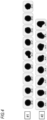
- FIG. 4 shows particle images of samples #1 and #2, which are images of particles having a particle diameter, corresponding to an average particle diameter, of 37 ⁇ 3 ⁇ m as examples of particle images used in obtaining the circularity shown in FIG. 3 . Average values of the circularity obtained from these particle images were 0.89 for sample #1 and 0.92 for sample #2.
- the circularity for each particle diameter shown in FIG. 3 is an average value likewise calculated for the particle diameter range of ⁇ 3 ⁇ m.
- [Table 1] Particle diameter ( ⁇ m) d10 d50 d90 Sample #1 24 38 57 Sample #2 23 36 51
- FIG. 3 shows that the particle size distribution of sample #1, to which nanoparticles had not been added, and the particle size distribution of sample #2, to which nanoparticles had been added, were highly akin to each other in median and width.
- the representative values for sample #1 and those for sample #2 shown in Table 1 are also considerably close to each other. That is, sample #1 and sample #2 had approximately the same particle size distribution, and it was ascertained that the particle size distribution of the sample particles had undergone substantially no change through the addition of nanoparticles.
- a comparison between the particle images of sample #1 and those of sample #2 given in FIG. 4 shows that in many of the particles, there was no large difference in particle shape between the two samples.
- the two samples were substantially equal also in the average value of the circularity estimated from these particle images.
- the two samples were substantially equal in the circularity throughout the whole particle diameter range. That is, it was ascertained that the circularity also had undergone substantially no change through the addition of nanoparticles.
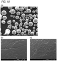
- FIG. 5 SEM images of sample #2 are shown.
- the low-magnification image of (a) of FIG. 5 metal particles having particle shapes and particle diameters corresponding with those of the particle images given in FIG. 4 were observed.
- the high-magnification image of (b) of FIG. 5 which shows an enlarged image of the surface of a metal particle, a large number of adherent particles ranging in size from tens of nanometers to hundreds of nanometers were observed in positions indicated as position A2.
- SiO 2 nanoparticles were ascertained to be dispersedly adherent to the surface of metal particles, no coarse agglomerates of SiO 2 nanoparticles were observed in the SEM images. If nanoparticles had formed coarse agglomerates such as ones having a particle diameter of 1 ⁇ m or larger and were present in an isolated state without being adherent to the metal particles, such agglomerate particles should have been observed in the space between metal particles in the low-magnification image of (a) of FIG. 5 (see (a) of FIG. 10 ). However, such particles are not observed in the actual SEM image of (a) of FIG. 5 . Such coarse agglomerates were not present in the state of being adherent to the surface of the metal particles either.
- the particle diameter and circularity of the particles constituting a powder material had undergone substantially no change even through the addition of nanoparticles, and it was ascertained that the addition of nanoparticles and the dispersing and classifying steps exerted no influence on the particle shape or particle size of the metal particles. It was also ascertained from the results of the examination with an SEM that the added nanoparticles were dispersedly adherent to the surface of the metal particles without forming coarse agglomerates.
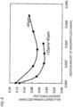
- FIG. 7 shows that sample #2, to which nanoparticles had been added, had a value reduced to about 40% of a value of sample #1, to which no nanoparticles had been added.
- results of measurements of bulk-density-normalized shear adhesive force ( ⁇ s/ ⁇ ) with different nanoparticle addition amounts are shown.
- the abscissa indicates the addition amount of nanoparticles based on the mass of the metal particles, the unit thereof being mass%.
- the results show that under any classification conditions, the bulk-density-normalized shear adhesive force decreased steeply as the addition amount increased, at least in a region up to an addition amount of 0.003 mass%, or further in a region up to an addition amount of about 0.010 mass%.
- the reason why the decrease in bulk-density-normalized shear adhesive force with increasing addition amount is saturated while the addition amount is increased in the region where the nanoparticle addition amount was larger is considered to be that even when the density of nanoparticles was further increased in the powder material in such a state that the metal particles were substantially not in contact with each other due to the effect of the nanoparticles present therebetween, then the increase in nanoparticle density was unable to increase the distance between the metal particles.
- the reason why the bulk-density-normalized shear adhesive force came to increase gently in the region where the nanoparticle addition amount was still larger is considered to be that an adhesive force was exerting between nanoparticles being adherent to a metal particle and nanoparticles being adherent to an adjacent metal particle to reduce the flowability of the metal particles having the nanoparticles being adherent thereto.
- the difference in classification conditions affects the magnitude of bulk-density-normalized shear adhesive force but exerts no considerable influence on the tendency of behavior with addition amount.
- sample #2 which had been produced by subjecting a powder material to dispersing and classifying, a dark fine powder was uniformly observed throughout the whole image shown in (a) of FIG. 9 , and no brightly observed particulate substances, such as those in (b) of FIG. 9 , were observed. That is, a highly uniform powder material was yielded as sample #2. This indicates that by subjecting a raw-material powder to the dispersing and classifying steps, the agglomerated state of SiO 2 nanoparticle agglomerates contained in the raw-material powder was loosened to increase the dispersibility of the nanoparticles.
- sample #3 which had been produced without performing dispersing and classifying, it was ascertained from the appearance of the powder material that SiO 2 nanoparticles had formed coarse agglomerates having sizes on the order of millimeter.
- the state of SiO 2 nanoparticles in a smaller area was observed with an SEM.
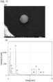
- SEM images of sample #3 are shown.
- metal particles having similar shape and size to those in the image of sample #2 in (a) of FIG. 5 were observed.
- particles having smaller particle diameters than those metal particles were distributed among the metal particles, as indicated by the arrow.
- the particle diameters of these small-diameter particles were roughly 1 ⁇ m or larger and 5 ⁇ m or smaller.
- the particle diameter of the particle indicated by the arrow was 2.8 ⁇ m.
- Such small-diameter particles were not observed in the image of sample #2 in (a) of FIG. 5 .
- the observed small-diameter particle is thought to be an agglomerate formed by the agglomeration of a large number of SiO 2 nanoparticles (or of fused-bodies thereof). It can be seen from these results of the SEM observation and EDX analysis that in sample #3, some of the SiO 2 nanoparticles had formed agglomerates having a particle diameter of 1 ⁇ m or larger and were dispersed in the state of being not adherent to the metal particles. That is, the SiO 2 nanoparticles had formed not only millimeter-order agglomerates such as those observed in (b) of FIG. 9 but also micrometer-order agglomerates.
- sample #3 which had been obtained by merely mixing metal particles and SiO 2 nanoparticles with a powder mixer, the SiO 2 nanoparticles had formed agglomerates having a particle diameter of 1 ⁇ m or larger and had been distributed, in an isolated state without being adherent to the metal particles, in the powder material.
- the density of SiO 2 nanoparticles being adherent to the surface of the metal particles was exceedingly low.
- sample #2 which had been produced through the dispersing step and the classifying step as explained above, the agglomerated state of SiO 2 nanoparticles had been loosened by the dispersing and classifying steps and, because of this, the SiO 2 nanoparticles were in the state of being finely dispersed and adherent to the surface of the metal particles, without being in the form of isolated agglomerates having a particle diameter of 1 ⁇ m or larger.
- sample #2 and sample #3 are compared with respect to the flowability of the powder material.
- FIG. 7 the bulk-density-normalized shear adhesive forces ( ⁇ s/ ⁇ ) of samples #1, #2, and #3 are shown.
- Sample #3 in which nanoparticles had been added and the mixture had only undergone mixing by a powder mixer, had a value reduced to about 90% of a value of sample #1, to which nanoparticles had not been added. This is thought to be because at least some of the nanoparticles were present between the metal particles to lower the attractive forces exerting between the metal particles and improve the flowability.
- sample #2 in which nanoparticles had been added and the mixture had undergone the dispersing and classifying steps, had a bulk-density-normalized shear adhesive force reduced to about 40% of that of sample #1 as explained above. That value of shear adhesive force was also as low as about 45% of the value of sample #3. It can be seen from these results that although the effect of improving the flowability of metal particles is obtained by merely adding nanoparticles to the metal particles and mixing the mixture, the nanoparticles can be made to exhibit a higher effect in lowering attractive forces exerting between the metal particles to improve the flowability, by performing the dispersing and classifying steps.
Landscapes
- Chemical & Material Sciences (AREA)
- Engineering & Computer Science (AREA)
- Materials Engineering (AREA)
- Organic Chemistry (AREA)
- Metallurgy (AREA)
- Mechanical Engineering (AREA)
- Manufacturing & Machinery (AREA)
- Composite Materials (AREA)
- Structural Engineering (AREA)
- Civil Engineering (AREA)
- Ceramic Engineering (AREA)
- Physics & Mathematics (AREA)
- Crystallography & Structural Chemistry (AREA)
- Nanotechnology (AREA)
- Thermal Sciences (AREA)
- Condensed Matter Physics & Semiconductors (AREA)
- General Physics & Mathematics (AREA)
- Powder Metallurgy (AREA)
- Inorganic Chemistry (AREA)
Claims (6)
- Pulvermaterial (P) mitMetallpartikeln (P1), die eine Eisenlegierung beinhalten und einen durchschnittlichen Partikeldurchmesser, d50, von 10 µm oder größer und 500 µm oder kleiner aufweisen, undNanopartikeln (P2), die ein Metall oder eine Metallverbindung beinhalten und die keiner Oberflächenbehandlung mit einer organischen Substanz unterzogen wurden,wobei die Nanopartikel (P2) verschmolzene Körper darstellen, in denen jeweils mehrere der Nanopartikel (P2) miteinander verschmolzen sind,dadurch gekennzeichnet, dassdie verschmolzenen Körper eine dendritische Struktur aufweisen.
- Pulvermaterial (P) gemäß Anspruch 1, wobei die Nanopartikel (P2) an den Metallpartikeln (P1) anhaften.
- Pulvermaterial (P) gemäß Anspruch 1 oder 2, wobei in dem Pulvermaterial zwischen den Metallpartikeln (P1) keine Agglomerate vorhanden sind, die jeweils aus den Nanopartikeln (P2) aufgebaut sind und einen Partikeldurchmesser von 1 µm oder größer aufweisen.
- Pulvermaterial (P) gemäß Anspruch 3, das keine Agglomerate aufweist, die im Zustand des Anhaftens an den Metallpartikel (P1) aus den Nanopartikeln (P2) aufgebaut sind und jeweils einen Partikeldurchmesser von 1 µm oder größer aufweisen.
- Pulvermaterial (P) gemäß einem der Ansprüche 1 bis 4, wobei die die Metallpartikel (P1) darstellende Eisenlegierung ein ausscheidungshärtender rostfreier Stahl ist.
- Pulvermaterial (P) gemäß einem der Ansprüche 1 bis 5, wobei die Nanopartikel (P2) Silicapartikel sind.
Applications Claiming Priority (3)
| Application Number | Priority Date | Filing Date | Title |
|---|---|---|---|
| JP2019203093 | 2019-11-08 | ||
| JP2020176818A JP7686956B2 (ja) | 2019-11-08 | 2020-10-21 | 粉末材料 |
| PCT/JP2020/041558 WO2021090918A1 (ja) | 2019-11-08 | 2020-11-06 | 粉末材料 |
Publications (3)
| Publication Number | Publication Date |
|---|---|
| EP4056299A1 EP4056299A1 (de) | 2022-09-14 |
| EP4056299A4 EP4056299A4 (de) | 2023-11-15 |
| EP4056299B1 true EP4056299B1 (de) | 2025-06-11 |
Family
ID=75849071
Family Applications (1)
| Application Number | Title | Priority Date | Filing Date |
|---|---|---|---|
| EP20884750.9A Active EP4056299B1 (de) | 2019-11-08 | 2020-11-06 | Pulvermaterial |
Country Status (6)
| Country | Link |
|---|---|
| US (1) | US20220388059A1 (de) |
| EP (1) | EP4056299B1 (de) |
| KR (1) | KR20220078645A (de) |
| CN (1) | CN114630720B (de) |
| CA (1) | CA3160308A1 (de) |
| WO (1) | WO2021090918A1 (de) |
Families Citing this family (1)
| Publication number | Priority date | Publication date | Assignee | Title |
|---|---|---|---|---|
| JP7615014B2 (ja) * | 2021-12-01 | 2025-01-16 | 山陽特殊製鋼株式会社 | 酸化物ナノ粒子を混合した積層造形用金属粉末および積層造形体 |
Family Cites Families (28)
| Publication number | Priority date | Publication date | Assignee | Title |
|---|---|---|---|---|
| JPH0628755B2 (ja) | 1991-02-22 | 1994-04-20 | 日清製粉株式会社 | 粉体分散機 |
| JP3999497B2 (ja) | 2001-11-12 | 2007-10-31 | 株式会社日清製粉グループ本社 | 粉体分級機 |
| EP1578559B1 (de) * | 2002-09-18 | 2009-03-18 | Ebara Corporation | Verfahren zum verbinden |
| JP2004156099A (ja) * | 2002-11-06 | 2004-06-03 | Teiboo Kk | 金属粉末射出成形による複合機能を有する焼結製品及びその製造方法 |
| JP2004190089A (ja) * | 2002-12-11 | 2004-07-08 | Kyoritsu Kagaku Sangyo Kk | 無機ナノ粒子融合又は融着構造体の製造方法及びその融合又は融着構造体 |
| JP2004332016A (ja) * | 2003-05-01 | 2004-11-25 | Seiko Epson Corp | 金属造粒粉末体及びその製造方法、並びに金属粉末体 |
| US20070053846A1 (en) * | 2005-08-31 | 2007-03-08 | Dave Rajesh N | Dry coating and downstream processing of cohesive powders |
| US7758784B2 (en) * | 2006-09-14 | 2010-07-20 | Iap Research, Inc. | Method of producing uniform blends of nano and micron powders |
| WO2010102655A2 (en) * | 2009-02-16 | 2010-09-16 | Bayer International Sa | A compound material comprising a metal and nano particles and a method for producing the same |
| WO2011149101A1 (ja) * | 2010-05-25 | 2011-12-01 | パナソニック電工株式会社 | 粉末焼結積層用金属粉末、それを用いた三次元形状造形物の製造方法および得られる三次元形状造形物 |
| JP6322886B2 (ja) * | 2012-11-20 | 2018-05-16 | セイコーエプソン株式会社 | 複合粒子、複合粒子の製造方法、圧粉磁心、磁性素子および携帯型電子機器 |
| EP3117934B1 (de) * | 2014-03-14 | 2019-05-01 | Sanyo Special Steel Co., Ltd. | Ausscheidungshärtungsedelstahlpulver und gesintertes kompakt |
| KR101604251B1 (ko) * | 2014-04-02 | 2016-03-18 | 한국생산기술연구원 | 유동성이 우수한 금속분말 및 그 제조방법 |
| WO2015194678A1 (ja) * | 2014-06-20 | 2015-12-23 | 株式会社フジミインコーポレーテッド | 粉末積層造形に用いる粉末材料およびそれを用いた粉末積層造形法 |
| CN105290388B (zh) * | 2014-07-04 | 2020-04-07 | 通用电气公司 | 粉末处理方法和相应处理过的粉末 |
| JP6303016B2 (ja) * | 2014-08-27 | 2018-03-28 | 株式会社日立製作所 | 積層造形物の製造方法 |
| JP6766399B2 (ja) * | 2016-03-28 | 2020-10-14 | 大同特殊鋼株式会社 | 焼結用粉末および焼結体 |
| US11052460B2 (en) * | 2017-02-01 | 2021-07-06 | Hrl Laboratories, Llc | Methods for nanofunctionalization of powders, and nanofunctionalized materials produced therefrom |
| EP3672746A1 (de) * | 2017-11-30 | 2020-07-01 | EOS GmbH Electro Optical Systems | Pulvermischung zur verwendung in der herstellung eines dreidimensionalen objektes durch ein verfahren zur generativen fertigung |
| CN108220644A (zh) * | 2017-12-14 | 2018-06-29 | 东睦新材料集团股份有限公司 | 一种纳米SiO2增强铝基复合材料的制备方法 |
| JP7039997B2 (ja) * | 2017-12-26 | 2022-03-23 | 大同特殊鋼株式会社 | 金属粉末材料の製造方法 |
| JP7024394B2 (ja) * | 2017-12-26 | 2022-02-24 | 大同特殊鋼株式会社 | 金属粉末材料 |
| JP6619039B2 (ja) * | 2018-03-14 | 2019-12-11 | 株式会社ExOne | バインダジェット法に用いる積層造形用粉末材料 |
| WO2019177642A1 (en) * | 2018-03-15 | 2019-09-19 | Hewlett-Packard Development Company, L.P. | Build material composition |
| JP2019203093A (ja) | 2018-05-24 | 2019-11-28 | 株式会社日本触媒 | 光定着用水性インク、及びそれを用いた膜の製造方法 |
| CN109014179B (zh) * | 2018-09-26 | 2020-08-18 | 中国科学院重庆绿色智能技术研究院 | 一种三维打印用球形金属基纳米陶瓷复合材料的制备方法及产品 |
| WO2020195842A1 (ja) * | 2019-03-22 | 2020-10-01 | 日本特殊陶業株式会社 | 圧粉磁心 |
| CN110200459B (zh) | 2019-04-16 | 2020-11-13 | 明光鑫烨制衣有限公司 | 一种可自动烘干的桌布 |
-
2020
- 2020-11-06 CA CA3160308A patent/CA3160308A1/en active Pending
- 2020-11-06 EP EP20884750.9A patent/EP4056299B1/de active Active
- 2020-11-06 WO PCT/JP2020/041558 patent/WO2021090918A1/ja not_active Ceased
- 2020-11-06 KR KR1020227014990A patent/KR20220078645A/ko active Pending
- 2020-11-06 CN CN202080076878.7A patent/CN114630720B/zh active Active
- 2020-11-06 US US17/774,910 patent/US20220388059A1/en active Pending
Also Published As
| Publication number | Publication date |
|---|---|
| CN114630720A (zh) | 2022-06-14 |
| WO2021090918A1 (ja) | 2021-05-14 |
| KR20220078645A (ko) | 2022-06-10 |
| CN114630720B (zh) | 2024-06-18 |
| CA3160308A1 (en) | 2021-05-14 |
| US20220388059A1 (en) | 2022-12-08 |
| EP4056299A1 (de) | 2022-09-14 |
| EP4056299A4 (de) | 2023-11-15 |
Similar Documents
| Publication | Publication Date | Title |
|---|---|---|
| EP3505274A1 (de) | Metallpulvermaterial | |
| KR102048062B1 (ko) | 티탄계 분말 및 그 용제품, 소결품 | |
| JP7176219B2 (ja) | 金属粉末材料および金属粉末材料の製造方法 | |
| JP7039997B2 (ja) | 金属粉末材料の製造方法 | |
| EP4056299B1 (de) | Pulvermaterial | |
| JP7686956B2 (ja) | 粉末材料 | |
| Soulier et al. | Nanocomposite powder for powder-bed-based additive manufacturing obtained by dry particle coating | |
| JP7427919B2 (ja) | 粉末材料の製造方法 | |
| US20220331858A1 (en) | SPHERICAL Ti-BASED POWDER AND MANUFACTURING METHOD THEREFOR | |
| JP7780619B2 (ja) | 酸化物ナノ粒子を混合した積層造形用金属粉末および積層造形体 | |
| CN111315507A (zh) | 粉末材料、增材制造用粉末材料和粉末材料的制造方法 | |
| EP3530377A1 (de) | Aluminiumpartikelgruppe und verfahren zur herstellung davon | |
| RU2707455C1 (ru) | Сферический порошок псевдосплава на основе вольфрама и способ его получения | |
| JP2008038163A5 (de) | ||
| JP2021123745A (ja) | 粉末材料の製造方法 | |
| JP4148521B2 (ja) | 球状微小銅粉および球状微小銅粉の製造方法 | |
| JP7296232B2 (ja) | 中実球状粉末の製造方法及び造形製品の製造方法 | |
| JP7378907B2 (ja) | 3d造形用混合粉末の製造方法 | |
| US20220288677A1 (en) | Powder material and producing method for the same | |
| Moazami-Goudarzi et al. | RETRACTED ARTICLE: Novel approach based on in situ powder metallurgy (IPM) method for embedding of SiC nanoparticles in aluminium powders | |
| JP7249811B2 (ja) | 金属粉末材料の製造方法 | |
| EP4317502A1 (de) | Pulvermaterial zur schichtweisen formung und verfahren zur herstellung eines geformten produkts unter verwendung des pulvermaterials | |
| JP2009215653A (ja) | コンポジット構造を有するナノ球状粒子、粉末、及び、その製造方法 | |
| JP2022140296A (ja) | 粉末材料 | |
| Colella et al. | Powder production techniques for high-pressure cold spray |
Legal Events
| Date | Code | Title | Description |
|---|---|---|---|
| STAA | Information on the status of an ep patent application or granted ep patent |
Free format text: STATUS: THE INTERNATIONAL PUBLICATION HAS BEEN MADE |
|
| PUAI | Public reference made under article 153(3) epc to a published international application that has entered the european phase |
Free format text: ORIGINAL CODE: 0009012 |
|
| STAA | Information on the status of an ep patent application or granted ep patent |
Free format text: STATUS: REQUEST FOR EXAMINATION WAS MADE |
|
| 17P | Request for examination filed |
Effective date: 20220505 |
|
| AK | Designated contracting states |
Kind code of ref document: A1 Designated state(s): AL AT BE BG CH CY CZ DE DK EE ES FI FR GB GR HR HU IE IS IT LI LT LU LV MC MK MT NL NO PL PT RO RS SE SI SK SM TR |
|
| DAV | Request for validation of the european patent (deleted) | ||
| DAX | Request for extension of the european patent (deleted) | ||
| A4 | Supplementary search report drawn up and despatched |
Effective date: 20231017 |
|
| RIC1 | Information provided on ipc code assigned before grant |
Ipc: B82Y 30/00 20110101ALN20231012BHEP Ipc: B22F 10/34 20210101ALN20231012BHEP Ipc: B22F 10/28 20210101ALN20231012BHEP Ipc: B22F 10/25 20210101ALN20231012BHEP Ipc: C22C 38/48 20060101ALI20231012BHEP Ipc: C22C 38/42 20060101ALI20231012BHEP Ipc: C22C 33/02 20060101ALI20231012BHEP Ipc: B33Y 70/10 20200101ALI20231012BHEP Ipc: B22F 1/16 20220101ALI20231012BHEP Ipc: B22F 1/00 20220101AFI20231012BHEP |
|
| GRAP | Despatch of communication of intention to grant a patent |
Free format text: ORIGINAL CODE: EPIDOSNIGR1 |
|
| STAA | Information on the status of an ep patent application or granted ep patent |
Free format text: STATUS: GRANT OF PATENT IS INTENDED |
|
| RIC1 | Information provided on ipc code assigned before grant |
Ipc: B82Y 30/00 20110101ALN20250110BHEP Ipc: B22F 10/34 20210101ALN20250110BHEP Ipc: B22F 10/28 20210101ALN20250110BHEP Ipc: B22F 10/25 20210101ALN20250110BHEP Ipc: C22C 38/48 20060101ALI20250110BHEP Ipc: C22C 38/42 20060101ALI20250110BHEP Ipc: C22C 33/02 20060101ALI20250110BHEP Ipc: B33Y 70/10 20200101ALI20250110BHEP Ipc: B22F 1/16 20220101ALI20250110BHEP Ipc: B22F 1/00 20220101AFI20250110BHEP |
|
| INTG | Intention to grant announced |
Effective date: 20250214 |
|
| RIN1 | Information on inventor provided before grant (corrected) |
Inventor name: ITO, YUKI Inventor name: KAMIMOTO, ASAKO |
|
| GRAS | Grant fee paid |
Free format text: ORIGINAL CODE: EPIDOSNIGR3 |
|
| GRAA | (expected) grant |
Free format text: ORIGINAL CODE: 0009210 |
|
| STAA | Information on the status of an ep patent application or granted ep patent |
Free format text: STATUS: THE PATENT HAS BEEN GRANTED |
|
| AK | Designated contracting states |
Kind code of ref document: B1 Designated state(s): AL AT BE BG CH CY CZ DE DK EE ES FI FR GB GR HR HU IE IS IT LI LT LU LV MC MK MT NL NO PL PT RO RS SE SI SK SM TR |
|
| REG | Reference to a national code |
Ref country code: GB Ref legal event code: FG4D |
|
| REG | Reference to a national code |
Ref country code: CH Ref legal event code: EP |
|
| REG | Reference to a national code |
Ref country code: IE Ref legal event code: FG4D |
|
| REG | Reference to a national code |
Ref country code: DE Ref legal event code: R096 Ref document number: 602020052751 Country of ref document: DE |
|
| PG25 | Lapsed in a contracting state [announced via postgrant information from national office to epo] |
Ref country code: ES Free format text: LAPSE BECAUSE OF FAILURE TO SUBMIT A TRANSLATION OF THE DESCRIPTION OR TO PAY THE FEE WITHIN THE PRESCRIBED TIME-LIMIT Effective date: 20250611 Ref country code: FI Free format text: LAPSE BECAUSE OF FAILURE TO SUBMIT A TRANSLATION OF THE DESCRIPTION OR TO PAY THE FEE WITHIN THE PRESCRIBED TIME-LIMIT Effective date: 20250611 |
|
| REG | Reference to a national code |
Ref country code: LT Ref legal event code: MG9D |
|
| PG25 | Lapsed in a contracting state [announced via postgrant information from national office to epo] |
Ref country code: NO Free format text: LAPSE BECAUSE OF FAILURE TO SUBMIT A TRANSLATION OF THE DESCRIPTION OR TO PAY THE FEE WITHIN THE PRESCRIBED TIME-LIMIT Effective date: 20250911 Ref country code: GR Free format text: LAPSE BECAUSE OF FAILURE TO SUBMIT A TRANSLATION OF THE DESCRIPTION OR TO PAY THE FEE WITHIN THE PRESCRIBED TIME-LIMIT Effective date: 20250912 |
|
| REG | Reference to a national code |
Ref country code: NL Ref legal event code: MP Effective date: 20250611 |
|
| PG25 | Lapsed in a contracting state [announced via postgrant information from national office to epo] |
Ref country code: BG Free format text: LAPSE BECAUSE OF FAILURE TO SUBMIT A TRANSLATION OF THE DESCRIPTION OR TO PAY THE FEE WITHIN THE PRESCRIBED TIME-LIMIT Effective date: 20250611 |
|
| PG25 | Lapsed in a contracting state [announced via postgrant information from national office to epo] |
Ref country code: HR Free format text: LAPSE BECAUSE OF FAILURE TO SUBMIT A TRANSLATION OF THE DESCRIPTION OR TO PAY THE FEE WITHIN THE PRESCRIBED TIME-LIMIT Effective date: 20250611 |
|
| PG25 | Lapsed in a contracting state [announced via postgrant information from national office to epo] |
Ref country code: RS Free format text: LAPSE BECAUSE OF FAILURE TO SUBMIT A TRANSLATION OF THE DESCRIPTION OR TO PAY THE FEE WITHIN THE PRESCRIBED TIME-LIMIT Effective date: 20250911 |
|
| PG25 | Lapsed in a contracting state [announced via postgrant information from national office to epo] |
Ref country code: LV Free format text: LAPSE BECAUSE OF FAILURE TO SUBMIT A TRANSLATION OF THE DESCRIPTION OR TO PAY THE FEE WITHIN THE PRESCRIBED TIME-LIMIT Effective date: 20250611 |
|
| PG25 | Lapsed in a contracting state [announced via postgrant information from national office to epo] |
Ref country code: NL Free format text: LAPSE BECAUSE OF FAILURE TO SUBMIT A TRANSLATION OF THE DESCRIPTION OR TO PAY THE FEE WITHIN THE PRESCRIBED TIME-LIMIT Effective date: 20250611 |
|
| PG25 | Lapsed in a contracting state [announced via postgrant information from national office to epo] |
Ref country code: PT Free format text: LAPSE BECAUSE OF FAILURE TO SUBMIT A TRANSLATION OF THE DESCRIPTION OR TO PAY THE FEE WITHIN THE PRESCRIBED TIME-LIMIT Effective date: 20251013 |
|
| REG | Reference to a national code |
Ref country code: AT Ref legal event code: MK05 Ref document number: 1801983 Country of ref document: AT Kind code of ref document: T Effective date: 20250611 |