EP4054872B1 - Motorrad mit hybridantrieb - Google Patents
Motorrad mit hybridantrieb Download PDFInfo
- Publication number
- EP4054872B1 EP4054872B1 EP20819863.0A EP20819863A EP4054872B1 EP 4054872 B1 EP4054872 B1 EP 4054872B1 EP 20819863 A EP20819863 A EP 20819863A EP 4054872 B1 EP4054872 B1 EP 4054872B1
- Authority
- EP
- European Patent Office
- Prior art keywords
- electric machine
- motorcycle
- carrier structure
- transmission
- swingarm
- Prior art date
- Legal status (The legal status is an assumption and is not a legal conclusion. Google has not performed a legal analysis and makes no representation as to the accuracy of the status listed.)
- Active
Links
Images


Classifications
-
- B—PERFORMING OPERATIONS; TRANSPORTING
- B62—LAND VEHICLES FOR TRAVELLING OTHERWISE THAN ON RAILS
- B62K—CYCLES; CYCLE FRAMES; CYCLE STEERING DEVICES; RIDER-OPERATED TERMINAL CONTROLS SPECIALLY ADAPTED FOR CYCLES; CYCLE AXLE SUSPENSIONS; CYCLE SIDECARS, FORECARS, OR THE LIKE
- B62K11/00—Motorcycles, engine-assisted cycles or motor scooters with one or two wheels
-
- B—PERFORMING OPERATIONS; TRANSPORTING
- B60—VEHICLES IN GENERAL
- B60K—ARRANGEMENT OR MOUNTING OF PROPULSION UNITS OR OF TRANSMISSIONS IN VEHICLES; ARRANGEMENT OR MOUNTING OF PLURAL DIVERSE PRIME-MOVERS IN VEHICLES; AUXILIARY DRIVES FOR VEHICLES; INSTRUMENTATION OR DASHBOARDS FOR VEHICLES; ARRANGEMENTS IN CONNECTION WITH COOLING, AIR INTAKE, GAS EXHAUST OR FUEL SUPPLY OF PROPULSION UNITS IN VEHICLES
- B60K6/00—Arrangement or mounting of plural diverse prime-movers for mutual or common propulsion, e.g. hybrid propulsion systems comprising electric motors and internal combustion engines
- B60K6/20—Arrangement or mounting of plural diverse prime-movers for mutual or common propulsion, e.g. hybrid propulsion systems comprising electric motors and internal combustion engines the prime-movers consisting of electric motors and internal combustion engines, e.g. HEVs
- B60K6/22—Arrangement or mounting of plural diverse prime-movers for mutual or common propulsion, e.g. hybrid propulsion systems comprising electric motors and internal combustion engines the prime-movers consisting of electric motors and internal combustion engines, e.g. HEVs characterised by apparatus, components or means specially adapted for HEVs
- B60K6/40—Arrangement or mounting of plural diverse prime-movers for mutual or common propulsion, e.g. hybrid propulsion systems comprising electric motors and internal combustion engines the prime-movers consisting of electric motors and internal combustion engines, e.g. HEVs characterised by apparatus, components or means specially adapted for HEVs characterised by the assembly or relative disposition of components
-
- B—PERFORMING OPERATIONS; TRANSPORTING
- B60—VEHICLES IN GENERAL
- B60K—ARRANGEMENT OR MOUNTING OF PROPULSION UNITS OR OF TRANSMISSIONS IN VEHICLES; ARRANGEMENT OR MOUNTING OF PLURAL DIVERSE PRIME-MOVERS IN VEHICLES; AUXILIARY DRIVES FOR VEHICLES; INSTRUMENTATION OR DASHBOARDS FOR VEHICLES; ARRANGEMENTS IN CONNECTION WITH COOLING, AIR INTAKE, GAS EXHAUST OR FUEL SUPPLY OF PROPULSION UNITS IN VEHICLES
- B60K6/00—Arrangement or mounting of plural diverse prime-movers for mutual or common propulsion, e.g. hybrid propulsion systems comprising electric motors and internal combustion engines
- B60K6/20—Arrangement or mounting of plural diverse prime-movers for mutual or common propulsion, e.g. hybrid propulsion systems comprising electric motors and internal combustion engines the prime-movers consisting of electric motors and internal combustion engines, e.g. HEVs
- B60K6/22—Arrangement or mounting of plural diverse prime-movers for mutual or common propulsion, e.g. hybrid propulsion systems comprising electric motors and internal combustion engines the prime-movers consisting of electric motors and internal combustion engines, e.g. HEVs characterised by apparatus, components or means specially adapted for HEVs
- B60K6/38—Arrangement or mounting of plural diverse prime-movers for mutual or common propulsion, e.g. hybrid propulsion systems comprising electric motors and internal combustion engines the prime-movers consisting of electric motors and internal combustion engines, e.g. HEVs characterised by apparatus, components or means specially adapted for HEVs characterised by the driveline clutches
- B60K6/387—Actuated clutches, i.e. clutches engaged or disengaged by electric, hydraulic or mechanical actuating means
-
- B—PERFORMING OPERATIONS; TRANSPORTING
- B60—VEHICLES IN GENERAL
- B60K—ARRANGEMENT OR MOUNTING OF PROPULSION UNITS OR OF TRANSMISSIONS IN VEHICLES; ARRANGEMENT OR MOUNTING OF PLURAL DIVERSE PRIME-MOVERS IN VEHICLES; AUXILIARY DRIVES FOR VEHICLES; INSTRUMENTATION OR DASHBOARDS FOR VEHICLES; ARRANGEMENTS IN CONNECTION WITH COOLING, AIR INTAKE, GAS EXHAUST OR FUEL SUPPLY OF PROPULSION UNITS IN VEHICLES
- B60K6/00—Arrangement or mounting of plural diverse prime-movers for mutual or common propulsion, e.g. hybrid propulsion systems comprising electric motors and internal combustion engines
- B60K6/20—Arrangement or mounting of plural diverse prime-movers for mutual or common propulsion, e.g. hybrid propulsion systems comprising electric motors and internal combustion engines the prime-movers consisting of electric motors and internal combustion engines, e.g. HEVs
- B60K6/42—Arrangement or mounting of plural diverse prime-movers for mutual or common propulsion, e.g. hybrid propulsion systems comprising electric motors and internal combustion engines the prime-movers consisting of electric motors and internal combustion engines, e.g. HEVs characterised by the architecture of the hybrid electric vehicle
- B60K6/48—Parallel type
-
- B—PERFORMING OPERATIONS; TRANSPORTING
- B60—VEHICLES IN GENERAL
- B60K—ARRANGEMENT OR MOUNTING OF PROPULSION UNITS OR OF TRANSMISSIONS IN VEHICLES; ARRANGEMENT OR MOUNTING OF PLURAL DIVERSE PRIME-MOVERS IN VEHICLES; AUXILIARY DRIVES FOR VEHICLES; INSTRUMENTATION OR DASHBOARDS FOR VEHICLES; ARRANGEMENTS IN CONNECTION WITH COOLING, AIR INTAKE, GAS EXHAUST OR FUEL SUPPLY OF PROPULSION UNITS IN VEHICLES
- B60K6/00—Arrangement or mounting of plural diverse prime-movers for mutual or common propulsion, e.g. hybrid propulsion systems comprising electric motors and internal combustion engines
- B60K6/20—Arrangement or mounting of plural diverse prime-movers for mutual or common propulsion, e.g. hybrid propulsion systems comprising electric motors and internal combustion engines the prime-movers consisting of electric motors and internal combustion engines, e.g. HEVs
- B60K6/50—Architecture of the driveline characterised by arrangement or kind of transmission units
- B60K6/54—Transmission for changing ratio
- B60K6/547—Transmission for changing ratio the transmission being a stepped gearing
-
- B—PERFORMING OPERATIONS; TRANSPORTING
- B60—VEHICLES IN GENERAL
- B60W—CONJOINT CONTROL OF VEHICLE SUB-UNITS OF DIFFERENT TYPE OR DIFFERENT FUNCTION; CONTROL SYSTEMS SPECIALLY ADAPTED FOR HYBRID VEHICLES; ROAD VEHICLE DRIVE CONTROL SYSTEMS FOR PURPOSES NOT RELATED TO THE CONTROL OF A PARTICULAR SUB-UNIT
- B60W30/00—Purposes of road vehicle drive control systems not related to the control of a particular sub-unit, e.g. of systems using conjoint control of vehicle sub-units
- B60W30/02—Control of vehicle driving stability
-
- B—PERFORMING OPERATIONS; TRANSPORTING
- B60—VEHICLES IN GENERAL
- B60W—CONJOINT CONTROL OF VEHICLE SUB-UNITS OF DIFFERENT TYPE OR DIFFERENT FUNCTION; CONTROL SYSTEMS SPECIALLY ADAPTED FOR HYBRID VEHICLES; ROAD VEHICLE DRIVE CONTROL SYSTEMS FOR PURPOSES NOT RELATED TO THE CONTROL OF A PARTICULAR SUB-UNIT
- B60W30/00—Purposes of road vehicle drive control systems not related to the control of a particular sub-unit, e.g. of systems using conjoint control of vehicle sub-units
- B60W30/18—Propelling the vehicle
- B60W30/18172—Preventing, or responsive to skidding of wheels
-
- B—PERFORMING OPERATIONS; TRANSPORTING
- B62—LAND VEHICLES FOR TRAVELLING OTHERWISE THAN ON RAILS
- B62M—RIDER PROPULSION OF WHEELED VEHICLES OR SLEDGES; POWERED PROPULSION OF SLEDGES OR SINGLE-TRACK CYCLES; TRANSMISSIONS SPECIALLY ADAPTED FOR SUCH VEHICLES
- B62M23/00—Transmissions characterised by use of other elements; Other transmissions
- B62M23/02—Transmissions characterised by use of other elements; Other transmissions characterised by the use of two or more dissimilar sources of power, e.g. transmissions for hybrid motorcycles
-
- B—PERFORMING OPERATIONS; TRANSPORTING
- B62—LAND VEHICLES FOR TRAVELLING OTHERWISE THAN ON RAILS
- B62M—RIDER PROPULSION OF WHEELED VEHICLES OR SLEDGES; POWERED PROPULSION OF SLEDGES OR SINGLE-TRACK CYCLES; TRANSMISSIONS SPECIALLY ADAPTED FOR SUCH VEHICLES
- B62M7/00—Motorcycles characterised by position of motor or engine
- B62M7/02—Motorcycles characterised by position of motor or engine with engine between front and rear wheels
- B62M7/04—Motorcycles characterised by position of motor or engine with engine between front and rear wheels below the frame
-
- B—PERFORMING OPERATIONS; TRANSPORTING
- B62—LAND VEHICLES FOR TRAVELLING OTHERWISE THAN ON RAILS
- B62M—RIDER PROPULSION OF WHEELED VEHICLES OR SLEDGES; POWERED PROPULSION OF SLEDGES OR SINGLE-TRACK CYCLES; TRANSMISSIONS SPECIALLY ADAPTED FOR SUCH VEHICLES
- B62M7/00—Motorcycles characterised by position of motor or engine
- B62M7/02—Motorcycles characterised by position of motor or engine with engine between front and rear wheels
- B62M7/06—Motorcycles characterised by position of motor or engine with engine between front and rear wheels directly under the saddle or seat
-
- B—PERFORMING OPERATIONS; TRANSPORTING
- B60—VEHICLES IN GENERAL
- B60K—ARRANGEMENT OR MOUNTING OF PROPULSION UNITS OR OF TRANSMISSIONS IN VEHICLES; ARRANGEMENT OR MOUNTING OF PLURAL DIVERSE PRIME-MOVERS IN VEHICLES; AUXILIARY DRIVES FOR VEHICLES; INSTRUMENTATION OR DASHBOARDS FOR VEHICLES; ARRANGEMENTS IN CONNECTION WITH COOLING, AIR INTAKE, GAS EXHAUST OR FUEL SUPPLY OF PROPULSION UNITS IN VEHICLES
- B60K6/00—Arrangement or mounting of plural diverse prime-movers for mutual or common propulsion, e.g. hybrid propulsion systems comprising electric motors and internal combustion engines
- B60K6/20—Arrangement or mounting of plural diverse prime-movers for mutual or common propulsion, e.g. hybrid propulsion systems comprising electric motors and internal combustion engines the prime-movers consisting of electric motors and internal combustion engines, e.g. HEVs
- B60K6/42—Arrangement or mounting of plural diverse prime-movers for mutual or common propulsion, e.g. hybrid propulsion systems comprising electric motors and internal combustion engines the prime-movers consisting of electric motors and internal combustion engines, e.g. HEVs characterised by the architecture of the hybrid electric vehicle
- B60K6/48—Parallel type
- B60K2006/4808—Electric machine connected or connectable to gearbox output shaft
-
- B—PERFORMING OPERATIONS; TRANSPORTING
- B60—VEHICLES IN GENERAL
- B60K—ARRANGEMENT OR MOUNTING OF PROPULSION UNITS OR OF TRANSMISSIONS IN VEHICLES; ARRANGEMENT OR MOUNTING OF PLURAL DIVERSE PRIME-MOVERS IN VEHICLES; AUXILIARY DRIVES FOR VEHICLES; INSTRUMENTATION OR DASHBOARDS FOR VEHICLES; ARRANGEMENTS IN CONNECTION WITH COOLING, AIR INTAKE, GAS EXHAUST OR FUEL SUPPLY OF PROPULSION UNITS IN VEHICLES
- B60K6/00—Arrangement or mounting of plural diverse prime-movers for mutual or common propulsion, e.g. hybrid propulsion systems comprising electric motors and internal combustion engines
- B60K6/20—Arrangement or mounting of plural diverse prime-movers for mutual or common propulsion, e.g. hybrid propulsion systems comprising electric motors and internal combustion engines the prime-movers consisting of electric motors and internal combustion engines, e.g. HEVs
- B60K6/42—Arrangement or mounting of plural diverse prime-movers for mutual or common propulsion, e.g. hybrid propulsion systems comprising electric motors and internal combustion engines the prime-movers consisting of electric motors and internal combustion engines, e.g. HEVs characterised by the architecture of the hybrid electric vehicle
- B60K6/48—Parallel type
- B60K2006/4833—Step up or reduction gearing driving generator, e.g. to operate generator in most efficient speed range
-
- B—PERFORMING OPERATIONS; TRANSPORTING
- B60—VEHICLES IN GENERAL
- B60W—CONJOINT CONTROL OF VEHICLE SUB-UNITS OF DIFFERENT TYPE OR DIFFERENT FUNCTION; CONTROL SYSTEMS SPECIALLY ADAPTED FOR HYBRID VEHICLES; ROAD VEHICLE DRIVE CONTROL SYSTEMS FOR PURPOSES NOT RELATED TO THE CONTROL OF A PARTICULAR SUB-UNIT
- B60W30/00—Purposes of road vehicle drive control systems not related to the control of a particular sub-unit, e.g. of systems using conjoint control of vehicle sub-units
- B60W30/02—Control of vehicle driving stability
- B60W30/04—Control of vehicle driving stability related to roll-over prevention
- B60W2030/041—Control of vehicle driving stability related to roll-over prevention about the pitch axis
-
- B—PERFORMING OPERATIONS; TRANSPORTING
- B60—VEHICLES IN GENERAL
- B60W—CONJOINT CONTROL OF VEHICLE SUB-UNITS OF DIFFERENT TYPE OR DIFFERENT FUNCTION; CONTROL SYSTEMS SPECIALLY ADAPTED FOR HYBRID VEHICLES; ROAD VEHICLE DRIVE CONTROL SYSTEMS FOR PURPOSES NOT RELATED TO THE CONTROL OF A PARTICULAR SUB-UNIT
- B60W2300/00—Indexing codes relating to the type of vehicle
- B60W2300/36—Cycles; Motorcycles; Scooters
-
- B—PERFORMING OPERATIONS; TRANSPORTING
- B60—VEHICLES IN GENERAL
- B60W—CONJOINT CONTROL OF VEHICLE SUB-UNITS OF DIFFERENT TYPE OR DIFFERENT FUNCTION; CONTROL SYSTEMS SPECIALLY ADAPTED FOR HYBRID VEHICLES; ROAD VEHICLE DRIVE CONTROL SYSTEMS FOR PURPOSES NOT RELATED TO THE CONTROL OF A PARTICULAR SUB-UNIT
- B60W2520/00—Input parameters relating to overall vehicle dynamics
- B60W2520/16—Pitch
-
- B—PERFORMING OPERATIONS; TRANSPORTING
- B60—VEHICLES IN GENERAL
- B60W—CONJOINT CONTROL OF VEHICLE SUB-UNITS OF DIFFERENT TYPE OR DIFFERENT FUNCTION; CONTROL SYSTEMS SPECIALLY ADAPTED FOR HYBRID VEHICLES; ROAD VEHICLE DRIVE CONTROL SYSTEMS FOR PURPOSES NOT RELATED TO THE CONTROL OF A PARTICULAR SUB-UNIT
- B60W2520/00—Input parameters relating to overall vehicle dynamics
- B60W2520/18—Roll
-
- B—PERFORMING OPERATIONS; TRANSPORTING
- B60—VEHICLES IN GENERAL
- B60W—CONJOINT CONTROL OF VEHICLE SUB-UNITS OF DIFFERENT TYPE OR DIFFERENT FUNCTION; CONTROL SYSTEMS SPECIALLY ADAPTED FOR HYBRID VEHICLES; ROAD VEHICLE DRIVE CONTROL SYSTEMS FOR PURPOSES NOT RELATED TO THE CONTROL OF A PARTICULAR SUB-UNIT
- B60W2520/00—Input parameters relating to overall vehicle dynamics
- B60W2520/26—Wheel slip
- B60W2520/263—Slip values between front and rear axle
-
- B—PERFORMING OPERATIONS; TRANSPORTING
- B60—VEHICLES IN GENERAL
- B60W—CONJOINT CONTROL OF VEHICLE SUB-UNITS OF DIFFERENT TYPE OR DIFFERENT FUNCTION; CONTROL SYSTEMS SPECIALLY ADAPTED FOR HYBRID VEHICLES; ROAD VEHICLE DRIVE CONTROL SYSTEMS FOR PURPOSES NOT RELATED TO THE CONTROL OF A PARTICULAR SUB-UNIT
- B60W2520/00—Input parameters relating to overall vehicle dynamics
- B60W2520/28—Wheel speed
-
- B—PERFORMING OPERATIONS; TRANSPORTING
- B60—VEHICLES IN GENERAL
- B60W—CONJOINT CONTROL OF VEHICLE SUB-UNITS OF DIFFERENT TYPE OR DIFFERENT FUNCTION; CONTROL SYSTEMS SPECIALLY ADAPTED FOR HYBRID VEHICLES; ROAD VEHICLE DRIVE CONTROL SYSTEMS FOR PURPOSES NOT RELATED TO THE CONTROL OF A PARTICULAR SUB-UNIT
- B60W2710/00—Output or target parameters relating to a particular sub-units
- B60W2710/08—Electric propulsion units
- B60W2710/083—Torque
-
- B—PERFORMING OPERATIONS; TRANSPORTING
- B62—LAND VEHICLES FOR TRAVELLING OTHERWISE THAN ON RAILS
- B62K—CYCLES; CYCLE FRAMES; CYCLE STEERING DEVICES; RIDER-OPERATED TERMINAL CONTROLS SPECIALLY ADAPTED FOR CYCLES; CYCLE AXLE SUSPENSIONS; CYCLE SIDECARS, FORECARS, OR THE LIKE
- B62K2204/00—Adaptations for driving cycles by electric motor
-
- Y—GENERAL TAGGING OF NEW TECHNOLOGICAL DEVELOPMENTS; GENERAL TAGGING OF CROSS-SECTIONAL TECHNOLOGIES SPANNING OVER SEVERAL SECTIONS OF THE IPC; TECHNICAL SUBJECTS COVERED BY FORMER USPC CROSS-REFERENCE ART COLLECTIONS [XRACs] AND DIGESTS
- Y02—TECHNOLOGIES OR APPLICATIONS FOR MITIGATION OR ADAPTATION AGAINST CLIMATE CHANGE
- Y02T—CLIMATE CHANGE MITIGATION TECHNOLOGIES RELATED TO TRANSPORTATION
- Y02T10/00—Road transport of goods or passengers
- Y02T10/60—Other road transportation technologies with climate change mitigation effect
- Y02T10/62—Hybrid vehicles
Definitions
- This invention relates to a hybrid-drive motorcycle.
- WO2018/173672 A1 discloses a hybrid-drive motorcycle having the features of the preamble of claim 1.
- WO2019/021227 A1 discloses a hybridization kit including an electric motor detachably mountable to the IC engine case of a motorcycle.
- the purpose of this invention is to provide a hybrid-drive motorcycle that makes it possible to overcome the above-mentioned drawbacks.
- a hybrid-drive motorcycle comprising a carrier structure, an endothermic engine mounted on or housed in the carrier structure, a front wheel, a rear wheel connected to the carrier structure through a swingarm, a gearbox connected to the endothermic engine through a primary transmission and to the rear wheel through a secondary transmission, a reversible electric machine, an auxiliary transmission connecting a shaft of the electric machine to an input shaft of the secondary transmission, and a support unit secured to the carrier structure and configured to support the electric machine below the swingarm.
- This arrangement also makes it possible to endow the electric machine with active anti-rearing or anti-spinning control functions by exerting a braking torque and simultaneously recharging the batteries without having to intervene on the power cut of the endothermic engine.
- the electric machine is located under the swingarm. This arrangement minimises the dynamic problems connected to the added mass of the electric machine, optimising motorcycle stability and riding safety.
- the electric machine is arranged basically symmetrically with respect to a vertical median plane of the motorcycle, which helps to optimise stability and safety.
- the electric machine can be selectively connected to the input shaft; in this way, in endothermic mode, it is possible to completely exclude the electric motor, avoiding the dragging of significant masses.
- the electric machine is preferably counter-rotating with respect to the secondary transmission, so as to at least partially compensate for the gyroscopic effect of the wheels.
- the number 1 indicates, as a whole, a hybrid-drive motorcycle, in particular a motorbike, manufactured according to this invention.
- the motorcycle 1 comprises, in a known way, a carrier structure 2 in which an endothermic engine 3 and a gearbox 4 are mounted or integrated ( Fig. 2 ).
- the carrier structure 2 may consist of a frame on which a crankcase housing the engine and the gearbox is mounted, of just the crankcase (in the case of a motorcycle with a load-bearing engine), or intermediate solutions comprising a crankcase and a partial frame.
- the motorcycle 1 is, in addition, equipped with a front wheel 5 and a rear wheel 6.
- the latter is attached to the carrier structure 2 by means of a swingarm 7, which is hinged to the carrier structure 2 at its front end and carries the wheel 6 at its rear end.
- the motorcycle ( Figure 2 ) is equipped with a primary transmission 8, e.g. with gears, which connects a drive shaft of the endothermic engine 3 to the gearbox 4, and a secondary transmission 9, e.g. by a chain, which connects an output shaft 10 of the gearbox 4 to the rear wheel 6.
- a primary transmission 8 e.g. with gears, which connects a drive shaft of the endothermic engine 3 to the gearbox 4
- a secondary transmission 9 e.g. by a chain, which connects an output shaft 10 of the gearbox 4 to the rear wheel 6.
- the output shaft 10 of the gearbox 4 is therefore the input shaft of the secondary transmission 9.
- the secondary transmission 9 may comprise, for example, a pinion 11 placed on the shaft 10, a rear sprocket 12 attached to the rear wheel 6, and a chain 13 engaging with the pinion 11 and the rear sprocket 12 ( Fig. 1 ) .
- the secondary transmission could be of any other known type, e.g. a toothed belt or drive shaft.
- the motorcycle 1 also comprises an electric machine M that is permanently or selectively connected to the secondary transmission 9, and, in particular, to the input shaft 10 of the same.
- the electric machine is preferably an axial-flow permanent magnet machine, with an external rotor, and is arranged with its own axis A perpendicular to a median longitudinal plane P of the vehicle.
- the electric machine M is permanently connected to the input shaft 10 of the secondary transmission 9, for example by means of an auxiliary chain transmission 14 comprising a pinion 50 connected to an output shaft 18 of the electric machine, a pinion 51 firmly connected to the output shaft of the gearbox 10 and a chain 52.
- the auxiliary transmission 14 could be a gear or belt transmission.
- the auxiliary transmission 14 comprises a reversing/decoupling unit 15 and a belt transmission 16 in series with each other.
- the reversing/decoupling unit 15 comprises a first toothed wheel 17 integral with the output shaft 18 of the electric machine M and a second toothed wheel 19 that can be selectively engaged with an idle shaft 20.
- the selective engagement of the toothed wheel 19 on the idle shaft 20 is implemented by means of a sliding sleeve 23 with front teeth, equipped with a synchroniser (not illustrated).
- the sleeve 23 acts as a decoupler for the electric machine M.
- the belt transmission 16 comprises a first crown wheel 21 on the idle shaft 20 and a second crown wheel 22 rotationally connected to the output shaft 10 of the gearbox 4.
- the electric machine M is mounted on the carrier structure 2 below the swingarm 7.
- the expression "below the swingarm 7" is to be understood as meaning that at least the main part of the electric machine M and the axis A of the electric machine itself are located below the swingarm 7; if not all the electric machine M is located below the swingarm 7, the latter must be configured so as not to interfere with the overall dimensions of the electric machine M under static and dynamic conditions.
- a top portion of the electric machine M may be located at the same height as the swingarm 7 during at least part of its travel, in which case the transverse dimensions of the electric machine M must be located between the two arms of the swingarm 7, so that no interference occurs.
- the electric machine M is conveniently arranged symmetrically in relation to a vertical median plane P of the motorcycle 1 ( Fig. 3 ).
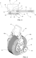
- Figure 4 illustrates a first embodiment of a support unit 40 for connecting the electric machine M to the carrier structure 2.
- the support unit 40 consists of a bracket comprising a top plate 41 designed to be arranged, in use, between the arms of the swingarm 7, in the transverse direction, and between the carrier structure 2 and the rear wheel 6, in the longitudinal direction.
- the top plate 41 is configured so that it can be fixed to the carrier structure 2 by means of screws and/or clamps, preferably using connection holes already existing in the structure itself (e.g. the swingarm 7 hinge holes).
- the unit 40 also comprises a pair of arms 42a, 42b extending downwards on opposite sides of the top plate 41 and arranged on axially opposite sides of the electric machine M.
- One of the arms 42a is fixed to the stator of the electric machine M, the other arm 42b ends with a ring-shaped support 54 for the output shaft 18 of the electric machine M, within which the shaft 18 is supported by a bearing (not illustrated).
- Figures 5 and 6 illustrate a different embodiment in which the unit 40 is composed of two brackets 43, 44 with respective top portions 45, 46 designed to be fixed to the opposite sides of the carrier structure 2 of the motorcycle 1, and for the purpose provided, with multiple fixing holes 47 each.
- the brackets 43, 44 also comprise respective arms 48, 49 fixed to or integral with the top portions 45, 46 and extending downwards from axially opposite sides of the electric machine M.
- the arm 48 is fixed to the stator of the electric machine M; the arm 49 terminates in a ring-shaped support 55 for the output shaft 18 of the electric machine M, within which the shaft 18 is supported by means of a bearing (not illustrated).
- brackets 43, 44 are conveniently shaped so that they can be arranged outside the swingarm 7, defining enough space with the carrier structure 2 to enable the passage and vertical travel of the swingarm 7.
- This solution has larger dimensions than the previous one but is more flexible and can be easily adapted to different motorcycle models, using attachment holes already present on the carrier structure.
- the brackets 43, 44 can replace the support brackets of the passenger pedals, and integrate the pedals themselves.
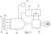
- Figure 7 illustrates a block diagram of the control of the electric machine M.
- a microprocessor control unit 25 receives input signals from a number of on-board sensors, including - with reference to the functions concerned here - at least one lateral inclination or roll sensor 26, one inclination or rearing sensor 27, one front wheel 5 angular velocity sensor 28, and one rear wheel 6 angular velocity sensor 29.
- the control unit 25 sends control signals to an inverter 30 joined to the electric machine M, which is connected to a battery pack 31 equipped with a management system (BMS) 32 that communicates with the control unit 25.
- BMS management system
- the inverter 30 is conveniently attached to a lower area of the carrier structure 2 and housed as low as possible, e.g. in front of the endothermic engine 3 ( Figure 1 ).
- the battery pack 31 is conveniently fixed to the inside of a tail piece 24 of the motorcycle 1, below the seat.
- the control unit also receives an input signal from an accelerator 33 in the form of a potentiometer conventionally controlled by a knob on the handlebar.
- the operation of the hybrid traction system of the motorcycle 1 is as follows.
- the motorcycle 1 is conventionally driven by just the endothermic engine 3.
- the sleeve 23 is disengaged; the electric machine M is excluded from the kinematic chain, and only the belt transmission 16 is dragged idle, with negligible inertia.
- the motorcycle is driven by just the electric machine M.
- the endothermic engine 3 is isolated and therefore does not introduce any inertia to the unwanted rotation.
- the electric machine is used as a regenerative brake to recharge the battery 31.
- both the endothermic engine 3 and the electric machine M are used simultaneously, so that the sum of the driving power ("boost") or braking power can thus be obtained, depending on the position of the accelerator 32.
- the control unit 25 distributes the torque between the endothermic engine 3 and the electric machine M on the basis of maps stored according to input signals, and in particular according to the speed, power demand, and load. In this case too, the electric machine M can be used as a regenerative brake to recharge the battery 31.
- complex control strategies can be implemented in particular operating situations that are identified on the basis of input signals, such as the following:
- the torque distribution maps between the thermal engine 3 and the electric machine M can be modified according to the lateral inclination or roll angle of the motorcycle.
- the torque contribution of the electric machine cancels out at a value of the maximum permissible inclination angle, and increase progressively as the inclination angle decreases (i.e. when exiting a curve).
- the mapping can be performed using not only the inclination angle but also the speed as input parameter.
- the reversing/decoupling unit if present, can be configured as a two-speed gearbox, in order to define a "short” gear, for obtaining a high breakaway torque in electric mode, and a "long” gear, to be used when the electric machine is used as a boost in combination with the endothermic engine.
- the electric machine, the support unit, and its control and supply means can also be supplied separately as a hybridization kit that can be applied to a conventional motorcycle that only has a thermal engine.
- the kit may conveniently comprise an interchangeable tail piece with the original motorcycle tail piece, in which the battery is integrated.
Landscapes
- Engineering & Computer Science (AREA)
- Mechanical Engineering (AREA)
- Chemical & Material Sciences (AREA)
- Combustion & Propulsion (AREA)
- Transportation (AREA)
- Automation & Control Theory (AREA)
- Electric Propulsion And Braking For Vehicles (AREA)
Claims (13)
- Motorrad mit Hybridantrieb, umfassend eine Trägerstruktur (2), einen Verbrennungsmotor (3), der an der Trägerstruktur (2) montiert oder darin untergebracht ist, ein Vorderrad (5), ein Hinterrad (6), das mittels eines Schwingarms (7) mit der Trägerstruktur (2) verbunden ist, ein Getriebe (4), das mittels eines Primärantriebs (8) mit dem Verbrennungsmotor (3) und mittels eines Sekundärantriebs (9) mit dem Hinterrad (6) verbunden ist, und eine umkehrbare elektrische Maschine (M), einen Hilfsantrieb (14), der die elektrische Maschine (M) mit einer Antriebswelle (10) des Sekundärantriebs (9) verbindet, und eine Stützeinheit (40), die an der Trägerstruktur (2) gesichert ist, dadurch gekennzeichnet, dass die Stützeinheit (40) so ausgestaltet ist, dass sie die elektrische Maschine (M) unter dem Schwingarm (7) stützt.
- Motorrad nach Anspruch 1, dadurch gekennzeichnet, dass die elektrische Maschine (M) im Wesentlichen symmetrisch zu einer vertikalen Mittelebene (P) des Motorrads (1) angeordnet ist.
- Motorrad nach Anspruch 1 oder 2, dadurch gekennzeichnet, dass die elektrische Maschine (M) in Bezug auf den Sekundärantrieb (9) gegenläufig ist.
- Motorrad nach einem der vorhergehenden Ansprüche, dadurch gekennzeichnet, dass der Hilfsantrieb (14) eine Umkehr/Entkopplungseinheit (15) umfasst, die so ausgestaltet ist, dass sie die elektrische Maschine (M) selektiv mit der Antriebswelle (10) des Sekundärantriebs (9) verbindet.
- Motorrad nach Anspruch 4, dadurch gekennzeichnet, dass die Umkehr/Entkopplungseinheit (15) ein erstes Zahnrad, das einteilig mit einer Abtriebswelle (18) der elektrischen Maschine (M) ist, und ein zweites Zahnrad (19) umfasst, das selektiv mit einer Leerlaufwelle (20) verbindbar ist.
- Motorrad nach Anspruch 5, dadurch gekennzeichnet, dass der Hilfsantrieb (14) einen Antrieb (16) umfasst, der die Leerlaufwelle (20) mit der Antriebswelle (10) des Sekundärantriebs (9) verbindet.
- Motorrad nach einem der vorhergehenden Ansprüche, dadurch gekennzeichnet, dass es einen Wechselrichter umfasst, der mit einem unteren Bereich der Trägerstruktur (2) verbunden ist.
- Motorrad nach einem der vorhergehenden Ansprüche, dadurch gekennzeichnet, dass es eine Steuereinheit (25) umfasst, die so ausgestaltet ist, dass sie das Antriebs- und Bremsmoment der elektrischen Maschine (M) als Reaktion auf Eingabesignale verändert, die von einem Schräglagewinkelsensor (26), einem Wheelie-Winkelsensor (27), einem Vorderrad-Winkelgeschwindigkeitssensor (28) und einem Hinterrad-Winkelgeschwindigkeitssensor (20) empfangen werden.
- Motorrad nach Anspruch 8, dadurch gekennzeichnet, dass die Steuereinheit (25) so ausgestaltet ist, dass sie eine Wheelie-Steuerung durchführt, in der die elektrische Maschine (M) ein Bremsmoment als eine Funktion der Ableitung des Neigungswinkels erzeugt.
- Motorrad nach Anspruch 8 oder 9, dadurch gekennzeichnet, dass die Steuereinheit (25) so ausgestaltet ist, dass sie eine Momentsteuerung durchführt, in der das Antriebsmoment, das von der elektrischen Maschine (M) erzeugt wird, als eine Funktion des Schräglagewinkels moduliert wird.
- Motorrad nach einem der Ansprüche 8 bis 10, dadurch gekennzeichnet, dass die Steuereinheit (25) so ausgestaltet ist, dass sie eine Antischlupfsteuerung durchführt, bei der die elektrische Maschine (M) ein Bremsmoment erzeugt, wenn die Winkelgeschwindigkeit des Hinterrads (6) höher ist als die Winkelgeschwindigkeit des Vorderrads (5).
- Motorrad nach einem der vorhergehenden Ansprüche, dadurch gekennzeichnet, dass die Stützeinheit (40) einen Bügel umfasst, der an der Trägerstruktur (2) befestigt ist und mit einem Paar Arme versehen ist, welche die elektrische Maschine (M) von axial entgegengesetzten Seiten stützen.
- Motorrad nach einem der Ansprüche 1 bis 11, dadurch gekennzeichnet, dass die Stützeinheit (40) ein Paar Bügel (43, 44) umfasst, die an entgegengesetzten Seiten der Trägerstruktur (2) befestigt sind und so ausgestaltet sind, dass sie sich in Bezug auf den Schwingarm (7) außerhalb erstrecken, wobei die Bügel (43, 44) mit der elektrischen Maschine (M) auf axial entgegengesetzten Seiten verbunden sind.
Applications Claiming Priority (2)
| Application Number | Priority Date | Filing Date | Title |
|---|---|---|---|
| IT102019000020398A IT201900020398A1 (it) | 2019-11-05 | 2019-11-05 | Motociclo a trazione ibrida e kit di ibridizzazione per un motociclo |
| PCT/IB2020/060422 WO2021090233A1 (en) | 2019-11-05 | 2020-11-05 | Hybrid-drive motorcycle and hybridization kit for a motorcycle |
Publications (3)
| Publication Number | Publication Date |
|---|---|
| EP4054872A1 EP4054872A1 (de) | 2022-09-14 |
| EP4054872C0 EP4054872C0 (de) | 2025-01-08 |
| EP4054872B1 true EP4054872B1 (de) | 2025-01-08 |
Family
ID=69811676
Family Applications (1)
| Application Number | Title | Priority Date | Filing Date |
|---|---|---|---|
| EP20819863.0A Active EP4054872B1 (de) | 2019-11-05 | 2020-11-05 | Motorrad mit hybridantrieb |
Country Status (7)
| Country | Link |
|---|---|
| US (1) | US12545355B2 (de) |
| EP (1) | EP4054872B1 (de) |
| JP (1) | JP2023500903A (de) |
| CN (1) | CN115279612B (de) |
| ES (1) | ES3006933T3 (de) |
| IT (1) | IT201900020398A1 (de) |
| WO (1) | WO2021090233A1 (de) |
Families Citing this family (4)
| Publication number | Priority date | Publication date | Assignee | Title |
|---|---|---|---|---|
| IT201900020398A1 (it) * | 2019-11-05 | 2021-05-05 | Efesto S A R L | Motociclo a trazione ibrida e kit di ibridizzazione per un motociclo |
| US20220355898A1 (en) * | 2021-05-04 | 2022-11-10 | Qingdao Choho Industrial Co.,Ltd. | Rear drive transmission system of motorcycle and motorcycle |
| DE102022209678A1 (de) | 2022-09-15 | 2024-03-21 | Robert Bosch Gesellschaft mit beschränkter Haftung | Verfahren und Fahrerassistenzsystem zum Betreiben eines Fahrzeugs |
| WO2025160635A1 (pt) * | 2024-02-01 | 2025-08-07 | Tractus Mobilidade Sustentavel Brasil Ltda | Sistema de hibridização universal para veículos |
Family Cites Families (24)
| Publication number | Priority date | Publication date | Assignee | Title |
|---|---|---|---|---|
| JPH05213253A (ja) * | 1992-02-07 | 1993-08-24 | Suzuki Motor Corp | 後二輪用電動車両 |
| JPH08175475A (ja) * | 1994-12-27 | 1996-07-09 | Yamaha Motor Co Ltd | モータ及びエンジンを備えた自動二輪車用ハイブリット式動力ユニット |
| JPH11303953A (ja) | 1997-05-01 | 1999-11-02 | Link Up:Kk | 駆動力伝達装置 |
| JP2004210072A (ja) * | 2002-12-27 | 2004-07-29 | Yamaha Motor Co Ltd | 電動二輪車 |
| JP4337365B2 (ja) * | 2003-02-28 | 2009-09-30 | スズキ株式会社 | 自動二輪車のバッテリー保持構造 |
| JP4667090B2 (ja) * | 2005-03-16 | 2011-04-06 | ヤマハ発動機株式会社 | ハイブリッド車両の駆動ユニット、ハイブリッド車両及び二輪車 |
| JP4755039B2 (ja) * | 2006-07-25 | 2011-08-24 | ヤマハ発動機株式会社 | ハイブリッド式自動二輪車 |
| US7942227B2 (en) * | 2008-03-07 | 2011-05-17 | Honda Motor Company, Ltd. | Motorcycle having a continuously variable transmission and a reduction gearset |
| JP5595227B2 (ja) * | 2010-10-29 | 2014-09-24 | 本田技研工業株式会社 | 電動二輪車 |
| JP5542626B2 (ja) * | 2010-11-10 | 2014-07-09 | 本田技研工業株式会社 | 鞍乗り型電動車両 |
| JP5749124B2 (ja) * | 2010-12-20 | 2015-07-15 | ボッシュ株式会社 | 二輪車用車両制御装置及びその方法 |
| JP2012148683A (ja) | 2011-01-19 | 2012-08-09 | Kironii Sangyo Kk | ハイブリッド車両用電動モータ駆動装置及び該装置を備えたハイブリッド車両 |
| WO2013061386A1 (ja) * | 2011-10-28 | 2013-05-02 | 川崎重工業株式会社 | 騎乗型電動車両 |
| CN103946108B (zh) * | 2011-12-28 | 2016-08-24 | 川崎重工业株式会社 | 跨乘式电动车辆 |
| TWI570020B (zh) * | 2013-11-15 | 2017-02-11 | Yamaha Motor Co Ltd | Electric locomotive |
| JP6894734B2 (ja) | 2017-03-22 | 2021-06-30 | 川崎重工業株式会社 | ハイブリッド車両 |
| JP2018203036A (ja) | 2017-06-02 | 2018-12-27 | ヤマハ発動機株式会社 | 鞍乗型車両 |
| CN110891854B (zh) * | 2017-07-26 | 2021-07-30 | Tvs电机股份有限公司 | 两轮车辆的传动辅助系统 |
| JP7143066B2 (ja) * | 2017-09-29 | 2022-09-28 | 日立Astemo株式会社 | 自動二輪車のピッチ角制御装置 |
| US11142284B2 (en) * | 2018-07-30 | 2021-10-12 | Harley-Davidson Motor Company Group, LLC | Drive belt assembly for an electric vehicle |
| JP7149161B2 (ja) * | 2018-10-30 | 2022-10-06 | 本田技研工業株式会社 | 鞍乗り型電動車両 |
| IT201800010046A1 (it) * | 2018-11-05 | 2020-05-05 | Efesto S A R L | Motociclo a trazione ibrida |
| IT201900020398A1 (it) * | 2019-11-05 | 2021-05-05 | Efesto S A R L | Motociclo a trazione ibrida e kit di ibridizzazione per un motociclo |
| IT202100010769A1 (it) * | 2021-04-28 | 2022-10-28 | Efesto S A R L | Motoslitta a trazione ibrida e kit di ibridizzazione per una motoslitta |
-
2019
- 2019-11-05 IT IT102019000020398A patent/IT201900020398A1/it unknown
-
2020
- 2020-11-05 US US17/774,373 patent/US12545355B2/en active Active
- 2020-11-05 WO PCT/IB2020/060422 patent/WO2021090233A1/en not_active Ceased
- 2020-11-05 CN CN202080091598.3A patent/CN115279612B/zh active Active
- 2020-11-05 EP EP20819863.0A patent/EP4054872B1/de active Active
- 2020-11-05 ES ES20819863T patent/ES3006933T3/es active Active
- 2020-11-05 JP JP2022526055A patent/JP2023500903A/ja active Pending
Also Published As
| Publication number | Publication date |
|---|---|
| EP4054872A1 (de) | 2022-09-14 |
| IT201900020398A1 (it) | 2021-05-05 |
| CN115279612A (zh) | 2022-11-01 |
| CN115279612B (zh) | 2025-10-28 |
| EP4054872C0 (de) | 2025-01-08 |
| WO2021090233A1 (en) | 2021-05-14 |
| US20220355885A1 (en) | 2022-11-10 |
| JP2023500903A (ja) | 2023-01-11 |
| US12545355B2 (en) | 2026-02-10 |
| ES3006933T3 (en) | 2025-03-19 |
Similar Documents
| Publication | Publication Date | Title |
|---|---|---|
| EP4054872B1 (de) | Motorrad mit hybridantrieb | |
| KR100201267B1 (ko) | 전동차량의 회생제동장치 | |
| US20080176707A1 (en) | Vehicle Drive Device | |
| EP1671832B1 (de) | Elektrische Radantriebseinrichtung | |
| CA2508969A1 (en) | Power module driving control apparatus and hybrid vehicle | |
| JP2007168690A (ja) | ハイブリッド車両 | |
| JP2005143169A (ja) | 電動車両 | |
| CN110799416A (zh) | 两轮车辆的驱动系统 | |
| JP4513612B2 (ja) | 車両のトルク配分制御装置 | |
| JP6548601B2 (ja) | 作業車 | |
| IT201800002810A1 (it) | Veicolo da lavoro ibrido elettrico con cambio di velocità e macchina elettrica | |
| GB2435869A (en) | Driveline and control method for hybrid vehicle | |
| WO2011019715A1 (en) | Motorized bicycle with front and rear wheel drive | |
| JP6200312B2 (ja) | 車両用電動機の制御装置 | |
| IT201800010046A1 (it) | Motociclo a trazione ibrida | |
| CN113840775A (zh) | 用于鞍座型车辆的驱动系统 | |
| US20240399847A1 (en) | Saddle-ride motorcycle of scooter type with hybrid propulsion | |
| JP3558688B2 (ja) | 原動機付き自転車 | |
| KR101414816B1 (ko) | 전기 자동차 | |
| JPH11125129A (ja) | 車 輌 | |
| JPH0516872A (ja) | 前後輪駆動二輪車 | |
| JP3620064B2 (ja) | モータ駆動型トラクター | |
| JP3593991B2 (ja) | 四輪駆動装置 | |
| JP3695371B2 (ja) | モータ駆動型トラクター | |
| CN207156915U (zh) | 一种永磁纯方波电机驱动的无机械差数器驱动桥 |
Legal Events
| Date | Code | Title | Description |
|---|---|---|---|
| STAA | Information on the status of an ep patent application or granted ep patent |
Free format text: STATUS: UNKNOWN |
|
| STAA | Information on the status of an ep patent application or granted ep patent |
Free format text: STATUS: THE INTERNATIONAL PUBLICATION HAS BEEN MADE |
|
| PUAI | Public reference made under article 153(3) epc to a published international application that has entered the european phase |
Free format text: ORIGINAL CODE: 0009012 |
|
| STAA | Information on the status of an ep patent application or granted ep patent |
Free format text: STATUS: REQUEST FOR EXAMINATION WAS MADE |
|
| 17P | Request for examination filed |
Effective date: 20220523 |
|
| AK | Designated contracting states |
Kind code of ref document: A1 Designated state(s): AL AT BE BG CH CY CZ DE DK EE ES FI FR GB GR HR HU IE IS IT LI LT LU LV MC MK MT NL NO PL PT RO RS SE SI SK SM TR |
|
| DAV | Request for validation of the european patent (deleted) | ||
| DAX | Request for extension of the european patent (deleted) | ||
| GRAP | Despatch of communication of intention to grant a patent |
Free format text: ORIGINAL CODE: EPIDOSNIGR1 |
|
| STAA | Information on the status of an ep patent application or granted ep patent |
Free format text: STATUS: GRANT OF PATENT IS INTENDED |
|
| INTG | Intention to grant announced |
Effective date: 20240729 |
|
| GRAS | Grant fee paid |
Free format text: ORIGINAL CODE: EPIDOSNIGR3 |
|
| GRAA | (expected) grant |
Free format text: ORIGINAL CODE: 0009210 |
|
| STAA | Information on the status of an ep patent application or granted ep patent |
Free format text: STATUS: THE PATENT HAS BEEN GRANTED |
|
| AK | Designated contracting states |
Kind code of ref document: B1 Designated state(s): AL AT BE BG CH CY CZ DE DK EE ES FI FR GB GR HR HU IE IS IT LI LT LU LV MC MK MT NL NO PL PT RO RS SE SI SK SM TR |
|
| REG | Reference to a national code |
Ref country code: GB Ref legal event code: FG4D |
|
| REG | Reference to a national code |
Ref country code: CH Ref legal event code: EP |
|
| REG | Reference to a national code |
Ref country code: DE Ref legal event code: R096 Ref document number: 602020044593 Country of ref document: DE |
|
| REG | Reference to a national code |
Ref country code: IE Ref legal event code: FG4D |
|
| U01 | Request for unitary effect filed |
Effective date: 20250130 |
|
| U07 | Unitary effect registered |
Designated state(s): AT BE BG DE DK EE FI FR IT LT LU LV MT NL PT RO SE SI Effective date: 20250206 |
|
| REG | Reference to a national code |
Ref country code: ES Ref legal event code: FG2A Ref document number: 3006933 Country of ref document: ES Kind code of ref document: T3 Effective date: 20250319 |
|
| PG25 | Lapsed in a contracting state [announced via postgrant information from national office to epo] |
Ref country code: RS Free format text: LAPSE BECAUSE OF FAILURE TO SUBMIT A TRANSLATION OF THE DESCRIPTION OR TO PAY THE FEE WITHIN THE PRESCRIBED TIME-LIMIT Effective date: 20250408 |
|
| PG25 | Lapsed in a contracting state [announced via postgrant information from national office to epo] |
Ref country code: PL Free format text: LAPSE BECAUSE OF FAILURE TO SUBMIT A TRANSLATION OF THE DESCRIPTION OR TO PAY THE FEE WITHIN THE PRESCRIBED TIME-LIMIT Effective date: 20250108 |
|
| PG25 | Lapsed in a contracting state [announced via postgrant information from national office to epo] |
Ref country code: NO Free format text: LAPSE BECAUSE OF FAILURE TO SUBMIT A TRANSLATION OF THE DESCRIPTION OR TO PAY THE FEE WITHIN THE PRESCRIBED TIME-LIMIT Effective date: 20250408 Ref country code: IS Free format text: LAPSE BECAUSE OF FAILURE TO SUBMIT A TRANSLATION OF THE DESCRIPTION OR TO PAY THE FEE WITHIN THE PRESCRIBED TIME-LIMIT Effective date: 20250508 |
|
| PG25 | Lapsed in a contracting state [announced via postgrant information from national office to epo] |
Ref country code: HR Free format text: LAPSE BECAUSE OF FAILURE TO SUBMIT A TRANSLATION OF THE DESCRIPTION OR TO PAY THE FEE WITHIN THE PRESCRIBED TIME-LIMIT Effective date: 20250108 |
|
| PG25 | Lapsed in a contracting state [announced via postgrant information from national office to epo] |
Ref country code: GR Free format text: LAPSE BECAUSE OF FAILURE TO SUBMIT A TRANSLATION OF THE DESCRIPTION OR TO PAY THE FEE WITHIN THE PRESCRIBED TIME-LIMIT Effective date: 20250409 |
|
| PG25 | Lapsed in a contracting state [announced via postgrant information from national office to epo] |
Ref country code: SM Free format text: LAPSE BECAUSE OF FAILURE TO SUBMIT A TRANSLATION OF THE DESCRIPTION OR TO PAY THE FEE WITHIN THE PRESCRIBED TIME-LIMIT Effective date: 20250108 |
|
| PG25 | Lapsed in a contracting state [announced via postgrant information from national office to epo] |
Ref country code: CZ Free format text: LAPSE BECAUSE OF FAILURE TO SUBMIT A TRANSLATION OF THE DESCRIPTION OR TO PAY THE FEE WITHIN THE PRESCRIBED TIME-LIMIT Effective date: 20250108 |
|
| PG25 | Lapsed in a contracting state [announced via postgrant information from national office to epo] |
Ref country code: SK Free format text: LAPSE BECAUSE OF FAILURE TO SUBMIT A TRANSLATION OF THE DESCRIPTION OR TO PAY THE FEE WITHIN THE PRESCRIBED TIME-LIMIT Effective date: 20250108 |
|
| PLBE | No opposition filed within time limit |
Free format text: ORIGINAL CODE: 0009261 |
|
| STAA | Information on the status of an ep patent application or granted ep patent |
Free format text: STATUS: NO OPPOSITION FILED WITHIN TIME LIMIT |
|
| 26N | No opposition filed |
Effective date: 20251009 |