EP4049844B1 - Liquid refill container for refilling liquid discharge apparatus with liquid, and reuse system using liquid refill container - Google Patents
Liquid refill container for refilling liquid discharge apparatus with liquid, and reuse system using liquid refill container Download PDFInfo
- Publication number
- EP4049844B1 EP4049844B1 EP21217385.0A EP21217385A EP4049844B1 EP 4049844 B1 EP4049844 B1 EP 4049844B1 EP 21217385 A EP21217385 A EP 21217385A EP 4049844 B1 EP4049844 B1 EP 4049844B1
- Authority
- EP
- European Patent Office
- Prior art keywords
- liquid
- refill container
- liquid storage
- pouring
- storage portion
- Prior art date
- Legal status (The legal status is an assumption and is not a legal conclusion. Google has not performed a legal analysis and makes no representation as to the accuracy of the status listed.)
- Active
Links
Images


Classifications
-
- B—PERFORMING OPERATIONS; TRANSPORTING
- B41—PRINTING; LINING MACHINES; TYPEWRITERS; STAMPS
- B41J—TYPEWRITERS; SELECTIVE PRINTING MECHANISMS, i.e. MECHANISMS PRINTING OTHERWISE THAN FROM A FORME; CORRECTION OF TYPOGRAPHICAL ERRORS
- B41J2/00—Typewriters or selective printing mechanisms characterised by the printing or marking process for which they are designed
- B41J2/005—Typewriters or selective printing mechanisms characterised by the printing or marking process for which they are designed characterised by bringing liquid or particles selectively into contact with a printing material
- B41J2/01—Ink jet
- B41J2/17—Ink jet characterised by ink handling
- B41J2/175—Ink supply systems ; Circuit parts therefor
- B41J2/17503—Ink cartridges
- B41J2/17506—Refilling of the cartridge
- B41J2/17509—Whilst mounted in the printer
-
- B—PERFORMING OPERATIONS; TRANSPORTING
- B65—CONVEYING; PACKING; STORING; HANDLING THIN OR FILAMENTARY MATERIAL
- B65D—CONTAINERS FOR STORAGE OR TRANSPORT OF ARTICLES OR MATERIALS, e.g. BAGS, BARRELS, BOTTLES, BOXES, CANS, CARTONS, CRATES, DRUMS, JARS, TANKS, HOPPERS, FORWARDING CONTAINERS; ACCESSORIES, CLOSURES, OR FITTINGS THEREFOR; PACKAGING ELEMENTS; PACKAGES
- B65D47/00—Closures with filling and discharging, or with discharging, devices
- B65D47/04—Closures with discharging devices other than pumps
- B65D47/06—Closures with discharging devices other than pumps with pouring spouts or tubes; with discharge nozzles or passages
- B65D47/12—Closures with discharging devices other than pumps with pouring spouts or tubes; with discharge nozzles or passages having removable closures
- B65D47/122—Threaded caps
-
- B—PERFORMING OPERATIONS; TRANSPORTING
- B41—PRINTING; LINING MACHINES; TYPEWRITERS; STAMPS
- B41J—TYPEWRITERS; SELECTIVE PRINTING MECHANISMS, i.e. MECHANISMS PRINTING OTHERWISE THAN FROM A FORME; CORRECTION OF TYPOGRAPHICAL ERRORS
- B41J2/00—Typewriters or selective printing mechanisms characterised by the printing or marking process for which they are designed
- B41J2/005—Typewriters or selective printing mechanisms characterised by the printing or marking process for which they are designed characterised by bringing liquid or particles selectively into contact with a printing material
- B41J2/01—Ink jet
- B41J2/17—Ink jet characterised by ink handling
- B41J2/175—Ink supply systems ; Circuit parts therefor
- B41J2/17503—Ink cartridges
- B41J2/17506—Refilling of the cartridge
-
- B—PERFORMING OPERATIONS; TRANSPORTING
- B41—PRINTING; LINING MACHINES; TYPEWRITERS; STAMPS
- B41J—TYPEWRITERS; SELECTIVE PRINTING MECHANISMS, i.e. MECHANISMS PRINTING OTHERWISE THAN FROM A FORME; CORRECTION OF TYPOGRAPHICAL ERRORS
- B41J2/00—Typewriters or selective printing mechanisms characterised by the printing or marking process for which they are designed
- B41J2/005—Typewriters or selective printing mechanisms characterised by the printing or marking process for which they are designed characterised by bringing liquid or particles selectively into contact with a printing material
- B41J2/01—Ink jet
- B41J2/17—Ink jet characterised by ink handling
- B41J2/175—Ink supply systems ; Circuit parts therefor
- B41J2/17503—Ink cartridges
- B41J2/17536—Protection of cartridges or parts thereof, e.g. tape
- B41J2/1754—Protection of cartridges or parts thereof, e.g. tape with means attached to the cartridge, e.g. protective cap
-
- B—PERFORMING OPERATIONS; TRANSPORTING
- B65—CONVEYING; PACKING; STORING; HANDLING THIN OR FILAMENTARY MATERIAL
- B65D—CONTAINERS FOR STORAGE OR TRANSPORT OF ARTICLES OR MATERIALS, e.g. BAGS, BARRELS, BOTTLES, BOXES, CANS, CARTONS, CRATES, DRUMS, JARS, TANKS, HOPPERS, FORWARDING CONTAINERS; ACCESSORIES, CLOSURES, OR FITTINGS THEREFOR; PACKAGING ELEMENTS; PACKAGES
- B65D2547/00—Closures with filling and discharging, or with discharging, devices
- B65D2547/04—Closures with discharging devices other than pumps
- B65D2547/06—Closures with discharging devices other than pumps with pouring spouts ot tubes; with discharge nozzles or passages
- B65D2547/063—Details of spouts
Definitions
- the present disclosure relates to a liquid refill container for refilling a liquid discharge apparatus with liquid, and a reuse system using a liquid refill container.
- liquid discharge apparatus typically an ink jet recording apparatus
- a liquid discharge apparatus in which a cartridge-shaped liquid storage tank is set in an apparatus main body and liquid is supplied from the liquid storage tank to a liquid discharge head of the liquid discharge apparatus.
- a liquid discharge apparatus as described in Japanese Patent Laid-Open No. 2015-178280 has come to be used.
- a liquid storage tank is fixed to the liquid discharge apparatus in advance, liquid is refilled from the outside to the liquid storage tank with the use of a bottle-shaped liquid refill container or the like, and the liquid storage tank is not replaced.
- liquid is refilled by opening the inlet of the liquid storage tank, removing a cap at the tip end of the liquid refill container, and inserting the tip end of the liquid refill container to the inlet.
- a liquid refill container entirely made of resin is generally used not only from the viewpoint that manufacturing through injection molding or the like is easy but also from the viewpoint of easiness of disposal after refilling of liquid is complete.
- Resin liquid refill containers can be reused by separately collecting the liquid refill containers without simply disposing of the liquid refill containers and then, for example, melting the liquid refill containers.
- a method of filling a liquid refill container, which is empty as a result of pouring liquid, with liquid again without disposal is conceivable.
- US 2019/039381 A1 discloses a liquid refill container according to the preambles of claims 1 and 2. Further liquid refill containers are known from JP 2018 134830 A , US 2018/208337 A1 , WO 93/18920 A1 , US 2017/120606 A1 , JP H09 240001 A and JP H11 29194 A .
- the present disclosure provides a liquid refill container suitable for reuse.
- the present disclosure in its first aspect provides a liquid refill container as specified in claims 1 to 9.
- the present disclosure in its second aspect provides a reuse system as specified in claim 10.
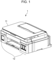
- FIG. 1 is a perspective view showing the outer appearance of the liquid discharge apparatus according to an embodiment of the present disclosure.
- the liquid discharge apparatus 1 shown in Fig. 1 is a so-called ink jet recording apparatus.
- the liquid discharge apparatus 1 shown in Fig. 1 includes a casing 11, and liquid storage tanks 12 disposed inside the casing 11. Each of the liquid storage tanks 12 contains ink that is liquid to be discharged to a record medium (not shown).
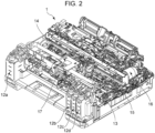
- Fig. 2 is a perspective view showing the internal configuration of a relevant part of the liquid discharge apparatus 1 shown in Fig. 1 .
- the liquid discharge apparatus 1 includes a conveying roller 13 for conveying a record medium (not shown), a carriage 15 provided with a recording head 14 that discharges liquid, and a carriage motor 16 for driving the carriage 15.
- the liquid discharge apparatus 1 of the present embodiment is a so-called serial ink jet recording apparatus.
- a record medium is a medium on which an image is formed by liquid discharged from the recording head 14. Examples of the record medium include paper, cloth, optical disk label side, plastic sheet, and overhead projector (OHP) sheet.
- the liquid container tanks 12 are fixedly mounted in the liquid discharge apparatus 1.
- Each of the liquid storage tanks 12 is a tank that contains liquid. Liquid contained in each liquid storage tank 12 is supplied to the recording head 14 via a liquid channel 17 and is discharged from the recording head 14.
- the liquid discharge apparatus 1 is an ink jet recording apparatus
- the liquid is so-called ink.
- four-color (for example, cyan, magenta, yellow, and black) inks are used as liquid, and the four-color liquid storage tanks 12a to 12d that respectively contain color inks.
- black ink is contained in the liquid storage tank 12a
- cyan ink is contained in the liquid storage tank 12b
- magenta ink is contained in the liquid storage tank 12c
- yellow ink is contained in the liquid storage tank 12d.
- the liquid storage tanks 12a to 12d each are disposed at the front side portion of the liquid discharge apparatus 1 inside the casing 11.
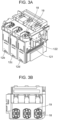
- Fig. 3A is an example of an enlarged perspective view of a portion of the liquid discharge apparatus 1 shown in Figs. 1 and 2 where the liquid storage tanks 12b to 12d are stored.
- Fig. 3B is a plan view of the portion where the liquid storage tanks 12b to 12d shown in Fig. 3A are stored when viewed from above.
- Each of the liquid storage tanks 12 includes a liquid storage tank body 121 for containing liquid, and a communication channel 122 that communicates with a liquid chamber in the liquid storage tank body 121.
- the liquid storage tank 12 includes an attachable tank cover (not shown) to, during times other than during refilling of liquid, cover the communication channel 122 and hermetically seal the liquid chamber inside the liquid storage tank body 121.
- the communication channel 122 includes two channels extending in parallel with each other in a vertical direction inside, and liquid in the liquid refill container 2 is configured to be poured into the liquid storage tank 12 by gas-liquid exchange.
- a socket 18 is provided at a portion of the liquid discharge apparatus 1 where the outlet 22a of the liquid refill container 2 is inserted.
- the socket 18 has protruding portions 19 that protrude inward from an inner peripheral wall.
- the socket 18 is provided for each liquid storage tank 12 and the shape of the protruding portions 19 is varied among the sockets 18. Only the liquid refill container 2 associated with the shape of the protruding portions 19 is able to be fitted to the socket 18. Thus, it is possible to prevent a refill mistake of liquid (a mistake of color).
- the protruding portions 19 are provided symmetrically at 180° with respect to the central axis of the communication channel 122. When recessed portions to be engaged with the protruding portions 19 of the socket 18 of the liquid discharge apparatus 1 are provided at the pouring portion 22 of the liquid refill container 2, it is possible to position the liquid refill container 2 with the socket 18, and it is possible to pour predetermined liquid to the liquid storage tank 12.
- Fig. 4 is a side view showing the outer appearance of the liquid refill container 2 to refill the liquid storage tank 12 with liquid.
- the liquid refill container 2 includes a liquid storage portion 21 that contains liquid, a pouring portion 22 connected to the liquid storage portion 21, and a cap portion 23 attached to the pouring portion 22.
- the liquid refill container 2 has a bottle shape as a whole.
- the liquid storage portion 21 contains liquid, occupies a half or more length of the liquid refill container 2 in the longitudinal direction, and serves as a main body portion of the liquid refill container 2. Since the liquid storage portion 21 is a portion that contains liquid, the liquid storage portion 21 can occupy two thirds or more of the length of the liquid refill container 2 in the longitudinal direction when the capacity is taken into consideration.
- the liquid storage portion 21 is made of a metal.
- the pouring portion 22 has an outlet 22a that is an outlet at the time of pouring liquid contained in the liquid storage portion 21.
- the pouring portion 22 is a portion having the function of pouring liquid.
- the cap portion 23 is attached to the pouring portion 22 and covers the outlet 22a. The cap portion 23 has a role in isolating the inside of the liquid storage portion 21 from outside air.
- Figs. 5A and 5B show the parts of the liquid refill container 2 of Fig. 4 .
- Fig. 5A is an exploded side view of the parts of the liquid refill container 2.
- Fig. 5B is a cross-sectional view of the liquid refill container 2 after the parts of the liquid refill container 2 shown in Fig. 5A are assembled.
- the liquid storage portion 21 of the liquid refill container 2 is made up of a bottle threaded portion 21a formed at the upper part, and a bottle storage portion 21b formed at the lower part.
- the bottle threaded portion 21a and the bottle storage portion 21b are integrated and are made of the same metal.
- the pouring portion 22 is made up of an outlet 22a for pouring liquid, a nozzle external threaded portion 22b on which an external thread structure is formed on the outer side, and a nozzle internal threaded portion 22c on which an internal thread structure is formed on the inner side.
- the pouring portion 22 is made of a resin. Examples of the material used to form the pouring portion 22 include polyethylene (PE) and polypropylene (PP).
- the nozzle internal threaded portion 22c of the pouring portion 22 is screwed to the bottle threaded portion 21a of the liquid storage portion 21.
- the pouring portion 22 is attached to the liquid storage portion 21 by means of screwing.
- Packing 28 is disposed at the connecting portion between the pouring portion 22 and the liquid storage portion 21.
- the packing 28 seals the connecting portion.
- the packing 28 has flexibility. Examples of the material used to form the packing 28 include butyl rubber, fluororubber, hydrogenated nitrile rubber, ethylene propylene dien monomer (EPDM), and silicone rubber.
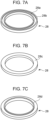
- Figs. 7A to 7C are perspective views each showing the packing 28.
- the packing 28 having a structure shown in Fig. 7A has two annular projections 28a, 28b on the liquid storage portion side.
- the structure of the packing 28 is the same as that of the packing 28 shown in Fig. 5B .
- the area between the projections 28a, 28b is in contact with the liquid storage portion 21.
- the side faces of projections 28a, 28b are also in contact with the liquid storage portion 21.
- the projections 28a, 28b sandwich both sides of a contact surface to increase sealing property.
- the packing 28 shown in Fig. 7B has no projection, and a portion on the liquid storage portion side is a flat smooth surface 28c.
- the packing 28 shown in Fig. 7C has an annular projection 28d on the liquid storage portion side.
- a projection of the packing 28 may be provided at a portion on the pouring portion side. A projection may be in contact with a member of the pouring portion and caused to be deformed.
- the rubber hardness of the packing 28 is preferably a Shore D hardness of higher than or equal to 10 and more preferably a Shore D hardness of higher than or equal to 30.
- Shore D hardness is preferably lower than or equal to 80, more preferably lower than or equal to 55, and further preferably lower than or equal to 45.
- a cap threaded portion 23a having an internal thread structure is disposed on the inner side of the lower part of the cap portion 23.
- the cap threaded portion 23a is screwed to the nozzle external threaded portion 22b of the pouring portion 22.
- a cap seal portion 23b is provided at the upper side of the cap portion 23.
- the cap seal portion 23b and part of the outlet 22a are fitted to each other by means of screwing, and the outlet 22a is hermetically sealed.
- the nozzle internal threaded portion 22c is screwed to the bottle threaded portion 21a, and the pouring portion 22 and the liquid storage portion 21 are joined by means of screwing.
- the liquid storage portion 21 of the liquid refill container 2 is made of a metal.
- the metal used to form the liquid storage portion 21 can be, for example, any one of a stainless steel, a steel, a porcelain enamel, and aluminum.
- the liquid refill container 2 is collected, and the metal liquid storage portion 21 is washed.
- a washing method for the liquid storage portion 21 include a washing method using water or hot water and a washing method using a predetermined detergent. After washing, when liquid is poured into the liquid storage portion 21 again and the liquid storage portion 21 is set in the liquid refill container 2 for use, the liquid refill container 2 is reusable, so it is environmentally beneficial.
- the liquid refill container 2 is made of a metal.
- the liquid refill container 2 is made of a resin, liquid adhering to the liquid refill container 2 may be difficult to be completely removed.
- the liquid refill container 2 is made of a metal, the liquid refill container 2 is less prone to degradation even when washed and filled with liquid again, so it is more suitable to be reused as a liquid refill container.
- the liquid refill container 2 is made of a metal usually not used for a liquid refill container for refilling a liquid discharge apparatus with liquid.
- the internal capacity of the liquid storage portion 21 is not limited. On the assumption that liquid is poured into the liquid storage tank 12 and is discharged from a liquid discharge head of a liquid discharge apparatus, the internal capacity of the liquid storage portion 21 is preferably greater than or equal to 10 ml and less than or equal to 200 ml. Examples of the shape of a cross section perpendicular to the height direction (longitudinal direction) of the liquid storage portion 21 include circle, square, and rectangle.
- the liquid storage portion 21 can have a cylindrical shape or a rectangular parallelepiped shape.
- a seal 24 is provided on the inner side of the pouring portion 22.
- the seal 24 has an opening at its tip end.
- the communication channel 122 is to be inserted in the opening.
- a valve 25 is urged by a spring 26 toward the opening to seal the opening.
- Examples of the material used to form the seal 24 include a rubber and an elastomer.
- Examples of the material used to form the valve 25 include polyethylene (PE) and polypropylene (PP).
- Examples of the material used to form the spring 26 include a stainless steel.
- An end portion of the spring 26 on the side opposite to the valve 25 side is fixed by a holder 27.
- Examples of the material used to form the holder 27 include polyethylene (PE) and polypropylene (PP). The holder 27 is fixed to the pouring portion 22 by welding.
- the cap portion 23 is removed. Then, the liquid refill container 2 is fitted to the liquid storage tank 12.
- the liquid discharge apparatus-side communication channel 122 ( Fig. 3A ) is inserted into the pouring portion 22 through the opening of the seal 24 of the liquid refill container 2.
- the valve 25 is opened as a result of the insertion. Liquid in the liquid refill container 2 is supplied to the liquid chamber of the liquid storage tank body 121 via the communication channel 122 due to the water head difference.
- the valve 25 is opened by the protrusion at the time when the cap portion 23 is removed.
- the air pressure in the liquid refill container 2 is higher than the outside air pressure as well, flooding of liquid from the liquid storage tank 12 as a result of rapid inflow of liquid into the liquid storage tank 12 is reduced at the time of supplying the liquid storage tank 12 with liquid.
- the pouring portion 22 is attached to the liquid storage portion 21.
- a user removes the cap portion 23 from the pouring portion 22 by rotating the cap portion 23 and pours liquid.
- a user erroneously rotates (rotates in a direction opposite to the rotation direction of screwing) between the pouring portion 22 and the liquid storage portion 21 and separates the pouring portion 22 and the liquid storage portion 21 from each other, liquid may adhere to the hand.
- the cap portion 23 and the liquid storage portion 21 can be in different color systems, and the pouring portion 22 and the liquid storage portion 21 can be in the same color system.
- the liquid storage portion 21 is made of a metal, when the liquid storage portion 21 is not colored, the liquid storage portion 21 mostly has a gray color with the L* value of L*a*b* color specification system in the CIE color specification system in a range of greater than or equal to 10 and less than or equal to 95.
- the pouring portion 22 can also have a gray color with the L* value of L*a*b* color specification system in the CIE color specification system in a range of greater than or equal to 10 and less than or equal to 95.
- the cap portion 23 has a color of which the L* value does not fall within the range greater than or equal to 10 and less than or equal to 95, that is, for example, a white color.
- the rotation direction can be, on the contrary, set such that the pouring portion 22 is rotated in the counterclockwise direction with respect to the liquid storage portion 21 to screw the pouring portion 22 and the liquid storage portion 21 to each other.
- a user who newly purchases a liquid discharge apparatus or a user who already owns a liquid discharge apparatus makes a contract on a use of a liquid refill container with a maker that manufactures liquid refill containers.
- a liquid refill container is delivered from the maker to the user.
- the user pours liquid in the liquid refill container into the liquid storage tank to refill liquid into the liquid storage tank.
- An empty liquid refill container is returned from the user to the maker.
- the maker removes the liquid storage portion from the returned liquid refill container and washes the liquid storage portion, and manufactures a liquid refill container by reusing the liquid storage portion and assembling the pouring portion and the cap portion to the liquid storage portion.
- the user orders a liquid refill container to the maker at the stage at which a predetermined amount of liquid in the liquid storage tank of the liquid discharge apparatus has been used.
- the maker delivers a liquid refill container to the user again.
- the user supplies the liquid storage tank with liquid in the delivered liquid refill container and returns the empty liquid refill container to the maker again.
- the liquid refill container can be reused.
- a liquid refill container delivered from the maker can be the one washed and reused from a liquid refill container returned in the past from the user who has ordered the liquid refill container.
- a liquid refill container returned from another user may also be washed, reused, and delivered.
- An order for a liquid refill container may be automatically placed in accordance with the amount of usage of liquid in a liquid discharge apparatus or a usage period of the apparatus itself.
- the above-described example is a scheme that assumes to wash and reuse only the liquid storage portion 21.
- the pouring portion 22 and the cap portion 23 are difficult to be washed when made of a resin, and an assembly inside the pouring portion 22 is also difficult to be washed by removing the assembly, so, when only the liquid storage portion 21 is reused, reliability as a liquid refill container improves.
- parts other than the liquid storage portion 21 may be washed and reused.
- the packing 28 in the liquid refill container 2 is difficult to be reused due to concerns about creep; however, parts other than the packing 28 are relatively easily reused.
- a washing method for parts may be a washing method similar to that of the liquid storage portion 21 (described later).
- the flow of a manufacturing method for the liquid refill container 2 will be described with reference to Fig. 6 .
- the packing 28 and the seal 24 are press-fitted and inserted to the pouring portion 22 by using a handpress or the like.
- the valve 25 and the spring 26 are inserted into the holder 27.
- the assembled pouring portion 22 and holder 27 are welded to each other by using ultrasonic welding or the like to make a unit part of the pouring portion 22.
- the reused liquid storage portion 21 may have adhering liquid inside. For this reason, the inside of the liquid storage portion 21 is washed.
- the description will be made with reference to a specific example. Initially, the liquid storage portion 21 is immersed in pure water for 30 minutes to clean adhering liquid. Subsequently, the liquid storage portion 21 is washed for 60 minutes by using 60°C pure water (hot water), and dried for 120 minutes in a tank at 60°C.
- a liquid refill container (2) for refilling a liquid discharge apparatus (1) with liquid includes a liquid storage portion (21), a pouring portion (22), and a cap portion.
- the liquid storage portion is made of a metal and contains liquid.
- the pouring portion is removeably connected to the liquid storage portion and has an outlet (22a) for pouring the liquid.
- the cap portion (23) is removeably attached to the pouring portion and covers the outlet.
Landscapes
- Engineering & Computer Science (AREA)
- Mechanical Engineering (AREA)
- Closures For Containers (AREA)
- Photographic Developing Apparatuses (AREA)
- Ink Jet (AREA)
Applications Claiming Priority (1)
| Application Number | Priority Date | Filing Date | Title |
|---|---|---|---|
| JP2021028711A JP2022129862A (ja) | 2021-02-25 | 2021-02-25 | 液体吐出装置に液体を補充するための液体補充容器、および該液体補充容器を用いた再利用システム |
Publications (2)
| Publication Number | Publication Date |
|---|---|
| EP4049844A1 EP4049844A1 (en) | 2022-08-31 |
| EP4049844B1 true EP4049844B1 (en) | 2025-02-12 |
Family
ID=79164973
Family Applications (1)
| Application Number | Title | Priority Date | Filing Date |
|---|---|---|---|
| EP21217385.0A Active EP4049844B1 (en) | 2021-02-25 | 2021-12-23 | Liquid refill container for refilling liquid discharge apparatus with liquid, and reuse system using liquid refill container |
Country Status (5)
| Country | Link |
|---|---|
| US (3) | US11708197B2 (enExample) |
| EP (1) | EP4049844B1 (enExample) |
| JP (1) | JP2022129862A (enExample) |
| KR (1) | KR102878132B1 (enExample) |
| CN (1) | CN114953751A (enExample) |
Families Citing this family (1)
| Publication number | Priority date | Publication date | Assignee | Title |
|---|---|---|---|---|
| JP2022129862A (ja) * | 2021-02-25 | 2022-09-06 | キヤノン株式会社 | 液体吐出装置に液体を補充するための液体補充容器、および該液体補充容器を用いた再利用システム |
Family Cites Families (44)
| Publication number | Priority date | Publication date | Assignee | Title |
|---|---|---|---|---|
| CH616350A5 (en) * | 1976-10-21 | 1980-03-31 | Werding Winfried J | Diffusing device |
| US4573582A (en) * | 1984-04-23 | 1986-03-04 | Owens-Illinois, Inc. | Ring seal tamper indicating device |
| US4848947A (en) * | 1985-06-05 | 1989-07-18 | Pittway Corporation | Liquid applicator device with tilt valve |
| EP0378935B1 (fr) * | 1988-12-20 | 1992-09-23 | Societe Technique De Pulverisation (S.T.E.P.) | Dispositif pour distribuer un liquide ou un lait par goutte de petit volume et ensemble de distribution associée |
| GB9205870D0 (en) | 1992-03-18 | 1992-04-29 | Willett Int Ltd | Replenishment of reservoirs |
| DE29502783U1 (de) * | 1995-02-20 | 1996-06-20 | THERA Patent GmbH & Co. KG Gesellschaft für industrielle Schutzrechte, 82229 Seefeld | Behälter zum Lagern und Ausbringen einer Dentalmasse |
| JPH09240001A (ja) * | 1996-03-04 | 1997-09-16 | Canon Inc | インク再充填装置およびそのインク再充填方法 |
| JPH1129194A (ja) * | 1997-03-21 | 1999-02-02 | Toppan Printing Co Ltd | 化粧用液体包装容器リサイクルシステム及びリサイクル用洗浄装置及びリサイクル用充填装置及びリサイクル装置 |
| JPH11349026A (ja) * | 1998-06-03 | 1999-12-21 | Zojirushi Corp | 密閉容器 |
| US6378906B1 (en) * | 1999-12-09 | 2002-04-30 | Morgan Adhesives Company | Inserted label for monitoring use of a container |
| US20020118259A1 (en) * | 2000-03-29 | 2002-08-29 | Ranganathan Nadeepuram Kuppanna | Inking system and method |
| JP2002079689A (ja) * | 2000-09-07 | 2002-03-19 | Canon Inc | インクカートリッジの洗浄方法 |
| JP2003321121A (ja) * | 2002-04-30 | 2003-11-11 | Kyoraku Co Ltd | 容器のリターナブルシステム |
| JP4585738B2 (ja) * | 2002-09-04 | 2010-11-24 | テイカ製薬株式会社 | 点眼剤容器 |
| JP2005186984A (ja) * | 2003-12-25 | 2005-07-14 | Nippon Electric Glass Co Ltd | ガラスペースト包装体およびガラスペーストの包装方法 |
| JP2005239178A (ja) * | 2004-02-25 | 2005-09-08 | Peacock Vacuum Bottle Co Ltd | 携帯飲料容器 |
| JP4657739B2 (ja) * | 2005-01-25 | 2011-03-23 | 吉田プラ工業株式会社 | 位置決め容器 |
| JP4725265B2 (ja) * | 2005-03-31 | 2011-07-13 | ブラザー工業株式会社 | インクジェット記録装置 |
| JP2008196401A (ja) * | 2007-02-14 | 2008-08-28 | Toyota Motor Corp | エジェクタを備えたシステム |
| CA2762526A1 (en) * | 2009-05-22 | 2010-11-25 | Shinichi Ishikawa | Container for eye drops |
| US20110240677A1 (en) * | 2010-03-03 | 2011-10-06 | Walter Dwyer | Airless double-piston double-action pump and cosmetics bottle dispensing device |
| JP2013010518A (ja) * | 2011-06-28 | 2013-01-17 | Nitto Kinzoku Kogyo Kk | 蓋付き容器及び保持構造 |
| US20130126369A1 (en) * | 2011-11-18 | 2013-05-23 | Mocktail Beverages Inc. | Beverage container |
| JP2015143116A (ja) * | 2014-01-31 | 2015-08-06 | ユニバーサル製缶株式会社 | ライナ付キャップ |
| KR101493035B1 (ko) * | 2014-07-24 | 2015-02-17 | 주식회사 우심시스템 | 사용자가 스스로 잉크 충전 가능한 잉크젯 프린터용 잉크 카트리지 |
| EP3020649A1 (en) * | 2014-11-11 | 2016-05-18 | Kao Germany GmbH | Spout for a refill container |
| JP6264328B2 (ja) | 2015-06-11 | 2018-01-24 | セイコーエプソン株式会社 | 液体補充容器 |
| JP6901835B2 (ja) * | 2015-08-31 | 2021-07-14 | 花王株式会社 | スパウト付容器及び詰め替え方法 |
| JP6611564B2 (ja) * | 2015-10-30 | 2019-11-27 | キヤノン株式会社 | 液体収納ボトルおよび液体収納ボトルのパッケージ |
| JP6809121B2 (ja) * | 2016-10-17 | 2021-01-06 | セイコーエプソン株式会社 | ボトルセット |
| CN107487083B (zh) * | 2016-06-10 | 2020-09-22 | 精工爱普生株式会社 | 墨水补充容器 |
| CN111845094B (zh) * | 2016-06-10 | 2022-01-11 | 精工爱普生株式会社 | 墨水补充容器 |
| JP6759876B2 (ja) * | 2016-09-02 | 2020-09-23 | セイコーエプソン株式会社 | ボトルセット、ボトル |
| JP2018065608A (ja) * | 2016-10-21 | 2018-04-26 | 株式会社江商 | 詰め替え液体用容器連結構造および詰め替え液体用容器 |
| JP6907559B2 (ja) * | 2017-01-26 | 2021-07-21 | セイコーエプソン株式会社 | インクボトル |
| JP2018134830A (ja) | 2017-02-23 | 2018-08-30 | セイコーエプソン株式会社 | インク容器及びインク補給容器 |
| JP2018149785A (ja) * | 2017-03-15 | 2018-09-27 | セイコーエプソン株式会社 | インク補給容器 |
| JP6992307B2 (ja) * | 2017-07-31 | 2022-01-13 | セイコーエプソン株式会社 | インク補給容器 |
| JP7005992B2 (ja) * | 2017-08-03 | 2022-01-24 | セイコーエプソン株式会社 | インク補給容器、インク補給容器の製造方法 |
| JP6953906B2 (ja) * | 2017-08-30 | 2021-10-27 | セイコーエプソン株式会社 | インク補給容器 |
| DE102018003741B4 (de) * | 2018-03-16 | 2021-08-26 | Aptar Dortmund Gmbh | Abgabevorrichtung mit reibverschweißtem Ventilteller |
| JP7119791B2 (ja) * | 2018-08-31 | 2022-08-17 | ブラザー工業株式会社 | タンク |
| JP7082449B2 (ja) * | 2018-10-31 | 2022-06-08 | ザ プロクター アンド ギャンブル カンパニー | 有孔シュリンクスリーブを有する容器及び関連するプロセス |
| JP2022129862A (ja) * | 2021-02-25 | 2022-09-06 | キヤノン株式会社 | 液体吐出装置に液体を補充するための液体補充容器、および該液体補充容器を用いた再利用システム |
-
2021
- 2021-02-25 JP JP2021028711A patent/JP2022129862A/ja active Pending
- 2021-12-20 US US17/556,254 patent/US11708197B2/en active Active
- 2021-12-23 EP EP21217385.0A patent/EP4049844B1/en active Active
-
2022
- 2022-02-16 CN CN202210140278.3A patent/CN114953751A/zh active Pending
- 2022-02-16 KR KR1020220020107A patent/KR102878132B1/ko active Active
-
2023
- 2023-06-09 US US18/332,624 patent/US12297013B2/en active Active
-
2025
- 2025-04-22 US US19/186,310 patent/US20250250077A1/en active Pending
Also Published As
| Publication number | Publication date |
|---|---|
| US20250250077A1 (en) | 2025-08-07 |
| US20220267059A1 (en) | 2022-08-25 |
| CN114953751A (zh) | 2022-08-30 |
| KR20220121714A (ko) | 2022-09-01 |
| KR102878132B1 (ko) | 2025-10-28 |
| US20230322449A1 (en) | 2023-10-12 |
| US11708197B2 (en) | 2023-07-25 |
| JP2022129862A (ja) | 2022-09-06 |
| US12297013B2 (en) | 2025-05-13 |
| EP4049844A1 (en) | 2022-08-31 |
Similar Documents
| Publication | Publication Date | Title |
|---|---|---|
| EP3939794B1 (en) | Liquid storage container | |
| US10350896B2 (en) | Ink replenishment container | |
| CN111845094B (zh) | 墨水补充容器 | |
| CN107487083B (zh) | 墨水补充容器 | |
| US20250250077A1 (en) | Liquid refill container for refilling liquid discharge apparatus with liquid, and reuse system using liquid refill container | |
| JP7500313B2 (ja) | インク収容容器 | |
| JP2006513100A (ja) | 交換可能な液体容器のための液密シール構成 | |
| CN111746904B (zh) | 储液瓶 | |
| KR20170127210A (ko) | 조립 용기, 리필팩 및 펌프를 포함하는 용기 세트 및 이에 사용되는 스파우트 | |
| JP4926674B2 (ja) | 詰め替え用容器 | |
| US20240190608A1 (en) | Liquid replenishment container | |
| JP7536488B2 (ja) | 液体補給容器及び液体補給構造 | |
| JP7585652B2 (ja) | インク補給容器 | |
| US20250001761A1 (en) | Liquid replenishment container | |
| CN218054031U (zh) | 自动加料装置及3d打印机 | |
| CN111746903B (zh) | 储液瓶 | |
| CN100594165C (zh) | 用于储存和取出能流动介质的装置 | |
| JP2025068740A (ja) | インク収容容器 | |
| CN116061568A (zh) | 墨水补充容器 |
Legal Events
| Date | Code | Title | Description |
|---|---|---|---|
| PUAI | Public reference made under article 153(3) epc to a published international application that has entered the european phase |
Free format text: ORIGINAL CODE: 0009012 |
|
| STAA | Information on the status of an ep patent application or granted ep patent |
Free format text: STATUS: THE APPLICATION HAS BEEN PUBLISHED |
|
| AK | Designated contracting states |
Kind code of ref document: A1 Designated state(s): AL AT BE BG CH CY CZ DE DK EE ES FI FR GB GR HR HU IE IS IT LI LT LU LV MC MK MT NL NO PL PT RO RS SE SI SK SM TR |
|
| STAA | Information on the status of an ep patent application or granted ep patent |
Free format text: STATUS: REQUEST FOR EXAMINATION WAS MADE |
|
| 17P | Request for examination filed |
Effective date: 20230228 |
|
| RBV | Designated contracting states (corrected) |
Designated state(s): AL AT BE BG CH CY CZ DE DK EE ES FI FR GB GR HR HU IE IS IT LI LT LU LV MC MK MT NL NO PL PT RO RS SE SI SK SM TR |
|
| GRAP | Despatch of communication of intention to grant a patent |
Free format text: ORIGINAL CODE: EPIDOSNIGR1 |
|
| STAA | Information on the status of an ep patent application or granted ep patent |
Free format text: STATUS: GRANT OF PATENT IS INTENDED |
|
| INTG | Intention to grant announced |
Effective date: 20240801 |
|
| GRAS | Grant fee paid |
Free format text: ORIGINAL CODE: EPIDOSNIGR3 |
|
| GRAA | (expected) grant |
Free format text: ORIGINAL CODE: 0009210 |
|
| STAA | Information on the status of an ep patent application or granted ep patent |
Free format text: STATUS: THE PATENT HAS BEEN GRANTED |
|
| AK | Designated contracting states |
Kind code of ref document: B1 Designated state(s): AL AT BE BG CH CY CZ DE DK EE ES FI FR GB GR HR HU IE IS IT LI LT LU LV MC MK MT NL NO PL PT RO RS SE SI SK SM TR |
|
| REG | Reference to a national code |
Ref country code: GB Ref legal event code: FG4D |
|
| REG | Reference to a national code |
Ref country code: CH Ref legal event code: EP |
|
| REG | Reference to a national code |
Ref country code: DE Ref legal event code: R096 Ref document number: 602021025958 Country of ref document: DE |
|
| REG | Reference to a national code |
Ref country code: IE Ref legal event code: FG4D |
|
| REG | Reference to a national code |
Ref country code: NL Ref legal event code: MP Effective date: 20250212 |
|
| PG25 | Lapsed in a contracting state [announced via postgrant information from national office to epo] |
Ref country code: RS Free format text: LAPSE BECAUSE OF FAILURE TO SUBMIT A TRANSLATION OF THE DESCRIPTION OR TO PAY THE FEE WITHIN THE PRESCRIBED TIME-LIMIT Effective date: 20250512 |
|
| PG25 | Lapsed in a contracting state [announced via postgrant information from national office to epo] |
Ref country code: FI Free format text: LAPSE BECAUSE OF FAILURE TO SUBMIT A TRANSLATION OF THE DESCRIPTION OR TO PAY THE FEE WITHIN THE PRESCRIBED TIME-LIMIT Effective date: 20250212 |
|
| PG25 | Lapsed in a contracting state [announced via postgrant information from national office to epo] |
Ref country code: PL Free format text: LAPSE BECAUSE OF FAILURE TO SUBMIT A TRANSLATION OF THE DESCRIPTION OR TO PAY THE FEE WITHIN THE PRESCRIBED TIME-LIMIT Effective date: 20250212 |
|
| PG25 | Lapsed in a contracting state [announced via postgrant information from national office to epo] |
Ref country code: ES Free format text: LAPSE BECAUSE OF FAILURE TO SUBMIT A TRANSLATION OF THE DESCRIPTION OR TO PAY THE FEE WITHIN THE PRESCRIBED TIME-LIMIT Effective date: 20250212 |
|
| REG | Reference to a national code |
Ref country code: LT Ref legal event code: MG9D |
|
| PG25 | Lapsed in a contracting state [announced via postgrant information from national office to epo] |
Ref country code: NO Free format text: LAPSE BECAUSE OF FAILURE TO SUBMIT A TRANSLATION OF THE DESCRIPTION OR TO PAY THE FEE WITHIN THE PRESCRIBED TIME-LIMIT Effective date: 20250512 Ref country code: IS Free format text: LAPSE BECAUSE OF FAILURE TO SUBMIT A TRANSLATION OF THE DESCRIPTION OR TO PAY THE FEE WITHIN THE PRESCRIBED TIME-LIMIT Effective date: 20250612 |
|
| PG25 | Lapsed in a contracting state [announced via postgrant information from national office to epo] |
Ref country code: NL Free format text: LAPSE BECAUSE OF FAILURE TO SUBMIT A TRANSLATION OF THE DESCRIPTION OR TO PAY THE FEE WITHIN THE PRESCRIBED TIME-LIMIT Effective date: 20250212 |
|
| PG25 | Lapsed in a contracting state [announced via postgrant information from national office to epo] |
Ref country code: HR Free format text: LAPSE BECAUSE OF FAILURE TO SUBMIT A TRANSLATION OF THE DESCRIPTION OR TO PAY THE FEE WITHIN THE PRESCRIBED TIME-LIMIT Effective date: 20250212 |
|
| PG25 | Lapsed in a contracting state [announced via postgrant information from national office to epo] |
Ref country code: LV Free format text: LAPSE BECAUSE OF FAILURE TO SUBMIT A TRANSLATION OF THE DESCRIPTION OR TO PAY THE FEE WITHIN THE PRESCRIBED TIME-LIMIT Effective date: 20250212 Ref country code: PT Free format text: LAPSE BECAUSE OF FAILURE TO SUBMIT A TRANSLATION OF THE DESCRIPTION OR TO PAY THE FEE WITHIN THE PRESCRIBED TIME-LIMIT Effective date: 20250612 |
|
| PG25 | Lapsed in a contracting state [announced via postgrant information from national office to epo] |
Ref country code: GR Free format text: LAPSE BECAUSE OF FAILURE TO SUBMIT A TRANSLATION OF THE DESCRIPTION OR TO PAY THE FEE WITHIN THE PRESCRIBED TIME-LIMIT Effective date: 20250513 Ref country code: BG Free format text: LAPSE BECAUSE OF FAILURE TO SUBMIT A TRANSLATION OF THE DESCRIPTION OR TO PAY THE FEE WITHIN THE PRESCRIBED TIME-LIMIT Effective date: 20250212 |
|
| REG | Reference to a national code |
Ref country code: AT Ref legal event code: MK05 Ref document number: 1765744 Country of ref document: AT Kind code of ref document: T Effective date: 20250212 |
|
| PG25 | Lapsed in a contracting state [announced via postgrant information from national office to epo] |
Ref country code: SE Free format text: LAPSE BECAUSE OF FAILURE TO SUBMIT A TRANSLATION OF THE DESCRIPTION OR TO PAY THE FEE WITHIN THE PRESCRIBED TIME-LIMIT Effective date: 20250212 |
|
| PG25 | Lapsed in a contracting state [announced via postgrant information from national office to epo] |
Ref country code: SM Free format text: LAPSE BECAUSE OF FAILURE TO SUBMIT A TRANSLATION OF THE DESCRIPTION OR TO PAY THE FEE WITHIN THE PRESCRIBED TIME-LIMIT Effective date: 20250212 |
|
| PG25 | Lapsed in a contracting state [announced via postgrant information from national office to epo] |
Ref country code: DK Free format text: LAPSE BECAUSE OF FAILURE TO SUBMIT A TRANSLATION OF THE DESCRIPTION OR TO PAY THE FEE WITHIN THE PRESCRIBED TIME-LIMIT Effective date: 20250212 |
|
| PG25 | Lapsed in a contracting state [announced via postgrant information from national office to epo] |
Ref country code: IT Free format text: LAPSE BECAUSE OF FAILURE TO SUBMIT A TRANSLATION OF THE DESCRIPTION OR TO PAY THE FEE WITHIN THE PRESCRIBED TIME-LIMIT Effective date: 20250212 |
|
| PG25 | Lapsed in a contracting state [announced via postgrant information from national office to epo] |
Ref country code: AT Free format text: LAPSE BECAUSE OF FAILURE TO SUBMIT A TRANSLATION OF THE DESCRIPTION OR TO PAY THE FEE WITHIN THE PRESCRIBED TIME-LIMIT Effective date: 20250212 |
|
| PG25 | Lapsed in a contracting state [announced via postgrant information from national office to epo] |
Ref country code: EE Free format text: LAPSE BECAUSE OF FAILURE TO SUBMIT A TRANSLATION OF THE DESCRIPTION OR TO PAY THE FEE WITHIN THE PRESCRIBED TIME-LIMIT Effective date: 20250212 Ref country code: CZ Free format text: LAPSE BECAUSE OF FAILURE TO SUBMIT A TRANSLATION OF THE DESCRIPTION OR TO PAY THE FEE WITHIN THE PRESCRIBED TIME-LIMIT Effective date: 20250212 |
|
| PG25 | Lapsed in a contracting state [announced via postgrant information from national office to epo] |
Ref country code: RO Free format text: LAPSE BECAUSE OF FAILURE TO SUBMIT A TRANSLATION OF THE DESCRIPTION OR TO PAY THE FEE WITHIN THE PRESCRIBED TIME-LIMIT Effective date: 20250212 |
|
| PG25 | Lapsed in a contracting state [announced via postgrant information from national office to epo] |
Ref country code: SK Free format text: LAPSE BECAUSE OF FAILURE TO SUBMIT A TRANSLATION OF THE DESCRIPTION OR TO PAY THE FEE WITHIN THE PRESCRIBED TIME-LIMIT Effective date: 20250212 |