EP4044295A1 - Elektrode, batteriezelle, zellstapel und redox-flow-batteriesystem - Google Patents
Elektrode, batteriezelle, zellstapel und redox-flow-batteriesystem Download PDFInfo
- Publication number
- EP4044295A1 EP4044295A1 EP19948708.3A EP19948708A EP4044295A1 EP 4044295 A1 EP4044295 A1 EP 4044295A1 EP 19948708 A EP19948708 A EP 19948708A EP 4044295 A1 EP4044295 A1 EP 4044295A1
- Authority
- EP
- European Patent Office
- Prior art keywords
- carbon fiber
- region
- cell
- electrode
- sample
- Prior art date
- Legal status (The legal status is an assumption and is not a legal conclusion. Google has not performed a legal analysis and makes no representation as to the accuracy of the status listed.)
- Pending
Links
Images


Classifications
-
- H—ELECTRICITY
- H01—ELECTRIC ELEMENTS
- H01M—PROCESSES OR MEANS, e.g. BATTERIES, FOR THE DIRECT CONVERSION OF CHEMICAL ENERGY INTO ELECTRICAL ENERGY
- H01M8/00—Fuel cells; Manufacture thereof
- H01M8/18—Regenerative fuel cells, e.g. redox flow batteries or secondary fuel cells
-
- H—ELECTRICITY
- H01—ELECTRIC ELEMENTS
- H01M—PROCESSES OR MEANS, e.g. BATTERIES, FOR THE DIRECT CONVERSION OF CHEMICAL ENERGY INTO ELECTRICAL ENERGY
- H01M4/00—Electrodes
- H01M4/86—Inert electrodes with catalytic activity, e.g. for fuel cells
- H01M4/96—Carbon-based electrodes
-
- H—ELECTRICITY
- H01—ELECTRIC ELEMENTS
- H01M—PROCESSES OR MEANS, e.g. BATTERIES, FOR THE DIRECT CONVERSION OF CHEMICAL ENERGY INTO ELECTRICAL ENERGY
- H01M8/00—Fuel cells; Manufacture thereof
- H01M8/18—Regenerative fuel cells, e.g. redox flow batteries or secondary fuel cells
- H01M8/184—Regeneration by electrochemical means
- H01M8/188—Regeneration by electrochemical means by recharging of redox couples containing fluids; Redox flow type batteries
-
- Y—GENERAL TAGGING OF NEW TECHNOLOGICAL DEVELOPMENTS; GENERAL TAGGING OF CROSS-SECTIONAL TECHNOLOGIES SPANNING OVER SEVERAL SECTIONS OF THE IPC; TECHNICAL SUBJECTS COVERED BY FORMER USPC CROSS-REFERENCE ART COLLECTIONS [XRACs] AND DIGESTS
- Y02—TECHNOLOGIES OR APPLICATIONS FOR MITIGATION OR ADAPTATION AGAINST CLIMATE CHANGE
- Y02E—REDUCTION OF GREENHOUSE GAS [GHG] EMISSIONS, RELATED TO ENERGY GENERATION, TRANSMISSION OR DISTRIBUTION
- Y02E60/00—Enabling technologies; Technologies with a potential or indirect contribution to GHG emissions mitigation
- Y02E60/30—Hydrogen technology
- Y02E60/50—Fuel cells
Definitions
- the present disclosure relates to an electrode, a battery cell, a cell stack, and a redox flow battery system.
- a stacked body formed by stacking a porous plate and a fiber aggregate is used as an electrode of a battery cell.
- the porous plate is made of a porous carbon material formed to have a continuous three-dimensional network structure by physical bonding of carbons.
- the porous plate is subjected to heat treatment in order to increase the hydrophilicity of the carbons.
- the fiber aggregate is mainly made of a plurality of carbon fibers.
- An electrode according to the present disclosure is
- a battery cell according to the present disclosure includes the electrode according to the present disclosure.
- a cell stack according to the present disclosure includes the battery cell according to the present disclosure.
- a redox flow battery system according to the present disclosure includes the electrode according to the present disclosure, the battery cell according to the present disclosure, or the cell stack according to the present disclosure.
- a carbon fiber included in an electrode is not only excellent in hydrophilicity but also excellent in durability. This is because the carbon fiber excellent in hydrophilicity can come into good contact with an electrolyte, and thus, the electrode including the carbon fiber makes it easy to construct a redox flow battery system that can achieve a reduction in cell resistivity. This is also because the carbon fiber excellent in durability is difficult to become thin as a result of charging and discharging, and thus, the electrode including the carbon fiber makes it easy to construct a redox flow battery system that is usable for a long time.
- an object of the present disclosure is to provide an electrode, a battery cell and a cell stack, which make it easy to construct a redox flow battery system that is low in cell resistivity and usable for a long time.
- an object of the present disclosure is to provide a redox flow battery system that is low in cell resistivity and usable for a long time.
- the electrode according to the present disclosure, the battery cell according to the present disclosure and the cell stack according to the present disclosure make it easy to construct a redox flow battery system that is low in cell resistivity and usable for a long time.
- the redox flow battery system according to the present disclosure is low in cell resistivity and usable for a long time.
- An electrode according to one aspect of the present disclosure is an electrode including a carbon fiber, wherein
- the above-described electrode makes it easy to construct a redox flow battery system that is low in cell resistivity and usable for a long time. This is because the first region provided in a surface layer including the surface of the carbon fiber is excellent in hydrophilicity and durability as described below.
- the first region has a highly crystalline carbon crystal structure.
- Having a peak around 530 eV means that the first region contains oxygen. Since the first region containing oxygen is provided in the surface layer including the surface of the carbon fiber, the first region is excellent in hydrophilicity. Therefore, the carbon fiber can come into good contact with an electrolyte. Accordingly, the electrode including the carbon fiber makes it easy to construct an RF battery system that is low in cell resistivity.
- the first region having a highly crystalline carbon crystal structure is provided in the surface layer of the carbon fiber, the first region is excellent in durability. Being excellent in durability means that the carbon fiber is difficult to become thin as a result of charging and discharging of a redox flow battery system.
- the carbon fiber does not contain oxygen in a portion that is inner than the first region. Therefore, the crystallinity of the carbon crystal structure in the inner portion is higher, and thus, the durability of the carbon fiber is more excellent. Accordingly, the electrode including the carbon fiber makes it easy to construct a redox flow battery system that is usable for a long time.
- the above-described electrode makes it easier to construct a redox flow battery system that is usable for a long time.
- the reason for this is as follows. Since the second region does not substantially contain oxygen, the crystallinity of the carbon crystal structure in the second region is higher than that in the first layer. That is, the second region is more excellent in durability than the first region, and thus, the durability of the carbon fiber is more excellent.
- the first region and the second region may further have a peak around 291 eV.
- the above-described electrode makes it easier to construct a redox flow battery system that is usable for a long time.
- the reason for this is as follows. Having a peak around 291 eV means that the first region and the second region have a more highly crystalline carbon crystal structure. That is, the durability of the carbon fiber is more excellent, and thus, the durability of the electrode is more excellent.
- a ratio h2/h1 of a height h2 of the peak around 291 eV to a height h1 of the peak around 285 eV may be equal to or more than 1.1 and equal to or less than 2.
- the above-described electrode makes it easier to construct a redox flow battery system that is usable for a long time. This is because above-described ratio h2/h1 satisfies the above-described range, and thus, the crystallinity of the carbon crystal structure in the first region is higher.
- a ratio of the area S2 to the total area may be equal to or more than 0.1% and equal to or less than 30%.
- the first region Since the ratio of area S2 is equal to or more than 0.1%, the first region contains a sufficient amount of oxygen, and thus, the first region is excellent in hydrophilicity. Since the ratio of area S2 is equal to or less than 30%, the first region does not contain an excessive amount of oxygen. Therefore, the carbon crystallinity is difficult to decrease due to oxygen, and thus, the first region is excellent in durability.
- a battery cell according to one aspect of the present disclosure includes the electrode in any one of (1) described above to (5) described above.
- the above-described battery cell makes it easy to construct a redox flow battery system that is low in cell resistivity and usable for a long time. This is because the above-described battery cell includes the electrode excellent in hydrophilicity and durability.
- a cell stack according to one aspect of the present disclosure includes a plurality of battery cells in (6) described above.
- the above-described cell stack makes it easy to construct a redox flow battery system that is low in cell resistivity and usable for a long time. This is because the battery cell included in the cell stack includes the electrode excellent in hydrophilicity and durability.
- a redox flow battery system includes the electrode in any one of (1) described above to (5) described above, the battery cell in (6) described above, or the cell stack in (7) described above.
- the above-described redox flow battery system is low in cell resistivity and usable for a long time. This is because the above-described redox flow battery system includes the electrode excellent in hydrophilicity and durability, the battery cell including the electrode, or the cell stack including the battery cell.
- RF battery system 1 includes a battery cell 10 and a circulation mechanism.
- Battery cell 10 includes a positive electrode 14, a negative electrode 15, and a membrane 11 interposed between positive electrode 14 and negative electrode 15.
- the circulation mechanism circulates an electrolyte in battery cell 10.
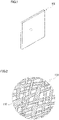
- One characteristic of RF battery system 1 according to the present embodiment is that at least one of positive electrode 14 and negative electrode 15 is composed of a specific electrode 100 ( Fig. 1 ).
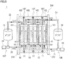
- one characteristic of RF battery system 1 according to the present embodiment is that electrode 100 includes specific carbon fibers 110 ( Fig. 3 ).
- RF battery system 1 is charged with electric power generated by a power generation unit 510 and stores the electric power, and discharges the stored electric power and supplies the electric power to a load 530 ( Fig. 4 ).
- RF battery system 1 is representatively connected between power generation unit 510 and load 530 with an AC/DC converter 500 and a transformer facility 520 interposed therebetween.
- power generation unit 510 include a photovoltaic power generation apparatus, a wind power generation apparatus, any other general power plant and the like.
- load 530 include an electric power consumer and the like.
- RF battery system 1 uses a positive electrode electrolyte and a negative electrode electrolyte.
- Each of the positive electrode electrolyte and the negative electrode electrolyte contains, as an active material, metal ions whose valence changes by oxidation reduction.
- Charging and discharging of RF battery system 1 are performed using a difference between an oxidation reduction potential of the ions contained in the positive electrode electrolyte and an oxidation reduction potential of the ions contained in the negative electrode electrolyte.
- a solid line arrow indicates charging
- a broken line arrow indicates discharging.
- RF battery system 1 is, for example, used for the load leveling application, the applications such as instantaneous voltage drop compensation and an emergency power supply, and the natural energy output leveling application for photovoltaic power generation, wind power generation and the like that are being introduced in large amounts.
- RF battery system 1 includes battery cell 10 separated into a positive electrode cell 12 and a negative electrode cell 13 by membrane 11 through which hydrogen ions transmit.
- Positive electrode cell 12 has positive electrode 14 built therein.
- a positive electrode circulation mechanism 10P causes the positive electrode electrolyte to circulate in positive electrode cell 12.
- Positive electrode circulation mechanism 10P includes a positive electrode electrolyte tank 18, a supply pipe 20, a discharge pipe 22, and a pump 24.
- Positive electrode electrolyte tank 18 stores the positive electrode electrolyte.
- Supply pipe 20 and discharge pipe 22 connect positive electrode cell 12 to positive electrode electrolyte tank 18.
- Pump 24 is provided midway along supply pipe 20.
- negative electrode cell 13 has negative electrode 15 built therein.
- a negative electrode circulation mechanism 10N causes the negative electrode electrolyte to circulate in negative electrode cell 13.
- Negative electrode circulation mechanism 10N includes a negative electrode electrolyte tank 19, a supply pipe 21, a discharge pipe 23, and a pump 25. Negative electrode electrolyte tank 19 stores the negative electrode electrolyte. Supply pipe 21 and discharge pipe 23 connect negative electrode cell 13 to negative electrode electrolyte tank 19. Pump 25 is provided midway along supply pipe 21.
- the positive electrode electrolyte and the negative electrode electrolyte are supplied from positive electrode electrolyte tank 18 and negative electrode electrolyte tank 19 through supply pipe 20 and supply pipe 21 to positive electrode cell 12 and negative electrode cell 13 by pump 24 and pump 25, respectively. Then, the positive electrode electrolyte and the negative electrode electrolyte are discharged from positive electrode cell 12 and negative electrode cell 13 through discharge pipe 22 and discharge pipe 23 to positive electrode electrolyte tank 18 and negative electrode electrolyte tank 19, thereby circulating in positive electrode cell 12 and negative electrode cell 13, respectively.
- pump 24 and pump 25 are stopped and the positive electrode electrolyte and the negative electrode electrolyte are not circulated.
- electrode 100 forms at least one of positive electrode 14 and negative electrode 15 ( Figs. 4 to 6 ).
- Electrode 100 includes a plurality of carbon fibers 110 ( Fig. 2 ). Examples of types of electrode 100 including the plurality of carbon fibers 110 include carbon felt, carbon cloth, carbon paper and the like. Some carbon fibers 110 have a first region 111 ( Fig. 3 ). Although details will be described below, carbon fiber 110 having first region 111 is excellent in hydrophilicity and durability. Therefore, a higher ratio of carbon fibers 110 having first region 111 to all carbon fibers 110 included in electrode 100 is more preferable. This is because electrode 100 makes it easy to construct RF battery system 1 that is low in cell resistivity and usable for a long time.
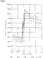
- First region 111 has peaks both around 285 eV and around 530 eV in energy loss spectra ( FIGs. 7 to 9 ).
- Fig. 7 is a graph showing five energy loss spectra obtained by analyzing a cross section of a carbon fiber of Sample No. 1 used in a belowdescribed test example by electron energy loss spectroscopy (EELS). In the following description, the energy loss spectrum may be simply referred to as "spectrum”.
- the cross section is a horizontal cross section orthogonal to a longitudinal direction of carbon fiber 110. Details of the graphs in Figs. 7 to 9 will be described below.
- Around 285 eV refers to equal to or more than 281 eV and equal to or less than 289 eV ( Figs. 7 and 8 ).
- Around 530 eV refers to equal to or more than 526 eV and equal to or less than 534 eV ( Figs. 7 and 9 ).
- the peak around 285 eV is a peak derived from a ⁇ ⁇ component.
- First region 111 having a peak around 530 eV means that first region 111 contains oxygen. Since first region 111 contains oxygen, first region 111 is excellent in hydrophilicity.
- First region 111 is formed in a surface layer including a surface of carbon fiber 110 ( Fig. 3 ).
- the surface of carbon fiber 110 refers to an outer circumferential surface.
- the surface layer refers to an area up to 10% of a diameter of carbon fiber 110 from the surface toward a center of carbon fiber 110.
- the center of carbon fiber 110 refers to a center of gravity of a region surrounded by a contour of the horizontal cross section of carbon fiber 110. When carbon fiber 110 has, for example, a circular outer shape, the center of carbon fiber 110 refers to the center of the circle.
- first region 111 containing oxygen is provided in the surface layer of carbon fiber 110, the surface layer is excellent in hydrophilicity. Therefore, carbon fiber 110 can come into good contact with an electrolyte.
- electrode 100 including this carbon fiber 110 makes it easy to construct RF battery system 1 that is low in cell resistivity.
- first region 111 having a highly crystalline carbon crystal structure is provided in the surface layer of carbon fiber 110, first region 111 is excellent in durability. Being excellent in durability means that carbon fiber 110 is difficult to become thin as a result of charging and discharging of RF battery system 1. Accordingly, electrode 100 including this carbon fiber 110 makes it easy to construct RF battery system 1 that is usable for a long time.
- first region 111 may be formed in an area up to 8% of the diameter of carbon fiber 110 from the surface toward the center of carbon fiber 110, and particularly, in an area up to 5% of the diameter of carbon fiber 110 from the surface toward the center of carbon fiber 110.
- First region 111 preferably further has a peak around 291 eV in the spectra ( Figs. 7 and 8 ).
- Around 291 eV refers to equal to or more than 287 eV and equal to or less than 295 eV.
- the peak around 291 eV is a peak derived from a ⁇ ⁇ component.
- First region 111 having a peak around 291 eV means that first region 111 has a highly crystalline carbon crystal structure. Therefore, first region 111 is excellent in durability. Accordingly, electrode 100 makes it easier to construct RF battery system 1 that is usable for a long time.
- a ratio h2/h1 of a height h2 of the peak around 291 eV to a height h1 of the peak around 285 eV is preferably equal to or more than 1.1 and equal to or less than 2 ( Figs. 7 and 8 ). This may be because above-described ratio h2/h1 in first region 111 satisfies the above-described range, and thus, the crystallinity of the carbon crystal structure in first region 111 is higher. Therefore, electrode 100 makes it easier to construct RF battery system 1 that is usable for a long time. Above-described ratio h2/h1 is further preferably equal to or more than 1.5 and equal to or less than 1.7.
- Each of heights h1 and h2 of the peaks refers to a distance to a top of the peak in each of the spectrum around 285 eV and the spectrum around 291 eV when a height of a spectrum around 280 eV is defined as zero.
- Around 280 eV refers to equal to or more than 276 eV and equal to or less than 284 eV.
- a ratio of area S2 to the total area is preferably equal to or more than 0.1% and equal to or less than 30%. Since the ratio of area S2 in first region 111 is equal to or more than 0.1%, first region 111 contains a sufficient amount of oxygen, and thus, first region 111 is excellent in hydrophilicity.
- first region 111 Since the ratio of area S2 in first region 111 is equal to or less than 30%, first region 111 does not contain an excessive amount of oxygen, and thus, first region 111 is excellent in durability.
- the ratio of area S2 in first region 111 is further preferably equal to or more than 1% and equal to or less than 25%, and particularly preferably equal to or more than 2% and equal to or less than 20%. A method for obtaining area S1 and area S2 will be described in detail below.
- Carbon fiber 110 preferably further has a second region 112.
- Second region 112 has no peak around 530 eV and has a peak around 285 eV in the spectra. That is, second region 112 does not contain oxygen and has a highly crystalline carbon crystal structure. Since second region 112 does not contain oxygen, the crystallinity of the carbon crystal structure in second region 112 is higher than that in first region 111. Therefore, second region 112 is more excellent in durability than first region 111.
- Second region 112 preferably further has a peak around 291 eV. This is because the durability of second region 112 is more excellent. Second region 112 is formed closer to the center than first region 111.
- ratio h2/h1 of height h2 of the peak around 291 eV to height h1 of the peak around 285 eV is preferably more than 1.3 and less than 2.
- ratio h2/h1 is particularly preferably equal to or more than 1.5 and equal to or less than 1.7.
- An average diameter of carbon fibers 110 is preferably equal to or more than 1 ⁇ m and equal to or less than 20 ⁇ m, for example. When the average diameter of carbon fibers 110 is equal to or more than 1 ⁇ m, it is easy to secure the strength of carbon fibers 110 themselves. When the average diameter of carbon fibers 110 is equal to or less than 20 ⁇ m, a surface area of carbon fibers 110 per unit weight can be increased, and thus, it is easy to sufficiently secure an area where the battery reaction occurs.
- the average diameter of carbon fibers 110 is further preferably equal to or more than 3 ⁇ m and equal to or less than 18 ⁇ m, and particularly preferably equal to or more than 5 ⁇ m and equal to or less than 16 ⁇ m.
- the average diameter of carbon fibers 110 is obtained by measuring circle equivalent diameters of 10 or more carbon fibers 110 and taking an average thereof. Circle equivalent diameters at one or more locations are measured per one carbon fiber 110. Circle equivalent diameters at a plurality of locations in the longitudinal direction may be obtained per one carbon fiber 110.
- the circle equivalent diameter refers to an equal area circle equivalent diameter obtained by true circle conversion of a horizontal cross-sectional area of carbon fiber 110.
- Carbon fiber 110 having first region 111 is manufactured, for example, by preparing a carbon fiber having a low content of impurities and subjecting the carbon fiber to heat treatment.
- the impurities include a metal element such as sodium or calcium.
- the heat treatment temperature is, for example, equal to or higher than 300°C and equal to or lower than 800°C.
- the heat treatment time is, for example, equal to or longer than 10 minutes and equal to or shorter than 120 minutes.
- the heat treatment atmosphere is, for example, the atmosphere containing oxygen, such as the air.
- the heat treatment temperature refers to a temperature of the carbon fiber itself.
- the heat treatment time refers to the time for which the carbon fiber is kept at the above-described temperature.
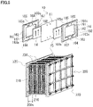
- battery cell 10 is normally formed inside a structure called "cell stack 200".
- Cell stack 200 is composed of a stacked body called “substack 200s", two end plates 220, and a tightening mechanism 230 (lower part of Fig. 6 ).
- Two end plates 220 sandwich the stacked body from both sides thereof.
- Tightening mechanism 230 tightens both end plates 220.
- the number of substack 220s may be singular or plural.
- the lower part of Fig. 6 shows, by way of example, the configuration including a plurality of substacks 200s.
- substack 200s is formed by stacking a cell frame 16, positive electrode 14, membrane 11, and negative electrode 15 in this order a plurality of times, and supply and discharge plates 210 (lower part of Fig. 6 ) are arranged at both ends of the stacked body.
- Cell frame 16 includes a bipolar plate 161 and a frame body 162.
- Frame body 162 surrounds an outer perimeter edge of bipolar plate 161.
- a surface of bipolar plate 161 and an inner perimeter surface of frame body 162 form a recessed portion 160 of cell frame 16 where positive electrode 14 or negative electrode 15 is arranged.
- One battery cell 10 is formed between bipolar plates 161 of adjacent cell frames 16.
- Positive electrode 14 and negative electrode 15 of adjacent battery cells 10 are arranged on the front surface and the back surface of bipolar plate 161. That is, positive electrode cell 12 and negative electrode cell 13 of adjacent battery cells 10 are formed on the front surface and the back surface of bipolar plate 161.
- Cell frame 16 includes an intermediate cell frame and an end cell frame.
- the intermediate cell frame is arranged between adjacent battery cells 10 of the above-described stacked body ( Figs. 4 to 6 ).
- the end cell frame is arranged at each of both ends of the above-described stacked body.
- positive electrode 14 of one battery cell 10 and negative electrode 15 of the other battery cell 10 are in contact with the front surface and the back surface of bipolar plate 161.
- one of positive electrode 14 and negative electrode 15 of battery cell 10 is in contact with one surface of bipolar plate 161, and there is no electrode on the other surface of bipolar plate 161.
- Both the intermediate cell frame and the end cell frame have the same configuration of the front surface and the back surface of cell frame 16.
- Frame body 162 supports bipolar plate 161.
- Frame body 162 forms therein a region for battery cell 10.
- Frame body 162 has a rectangular frame shape. That is, recessed portion 160 has a rectangular opening shape.
- Frame body 162 includes a liquid supply-side piece, and a liquid discharge-side piece that faces the liquid supply-side piece. Assuming that a direction in which the liquid supply-side piece and the liquid discharge-side piece face each other when cell frame 16 is seen in a plan view is defined as a longitudinal direction, and a direction orthogonal to the longitudinal direction is defined as a horizontal direction, the liquid supply-side piece is located on the lower side in the above-described longitudinal direction, and the liquid discharge-side piece is located on the upper side in the above-described longitudinal direction.
- the liquid supply-side piece includes liquid supply manifolds 163 and 164 and liquid supply slits 163s and 164s that supply the electrolyte to the inside of battery cell 10.
- the liquid discharge-side piece includes liquid discharge manifolds 165 and 166 and liquid discharge slits 165s and 166s that discharge the electrolyte to the outside of battery cell 10.
- the electrolyte flows in a direction from the lower side in the above-described longitudinal direction to the upper side in the above-described longitudinal direction of frame body 162.
- the liquid supply-side piece may have a liquid supply adjusting unit (not shown) at an inner edge thereof.
- the liquid supply adjusting unit diffuses, along the inner edge of the liquid supply-side piece, the electrolyte flowing through liquid supply slits 163s and 164s.
- the liquid discharge-side piece may have a liquid discharge adjusting unit (not shown) at an inner edge thereof.
- the liquid discharge adjusting unit collects the electrolyte flowing through positive electrode 14 (negative electrode 15) and causes the electrolyte to flow through liquid discharge slits 165s and 166s.
- a flow of each electrode electrolyte in cell frame 16 is as follows.
- the positive electrode electrolyte flows from liquid supply manifold 163 through liquid supply slits 163s and 164s formed in the liquid supply-side piece on the one surface side of frame body 162 to positive electrode 14.
- the positive electrode electrolyte flows from the lower side to the upper side of positive electrode 14.
- the positive electrode electrolyte is discharged to liquid discharge manifolds 165 and 166 through liquid discharge slits 165s and 166s formed in the liquid discharge-side piece.
- the supply and discharge of the negative electrode electrolyte is similar to that of the positive electrode electrolyte, except that they are performed on the other surface side of frame body 162.
- annular seal member 167 is arranged in an annular seal groove. Seal member 167 suppresses leakage of the electrolyte from battery cell 10.
- An O-ring, a flat packing or the like can, for example, be used as seal member 167.
- the positive electrode electrolyte and the negative electrode electrolyte are supplied to positive electrode 14 and negative electrode 15 in a circulating manner by positive electrode circulation mechanism 10P and negative electrode circulation mechanism 10N, respectively. As a result of this circulation, charging and discharging are performed with the valence change reaction of the active material ions contained in the positive electrode electrolyte and the negative electrode electrolyte.
- the active material of the positive electrode electrolyte contains one or more selected from the group consisting of manganese ions, vanadium ions, iron ions, polyacid, a quinone derivative, and amine.
- the active material of the negative electrode electrolyte contains one or more selected from the group consisting of titanium ions, vanadium ions, chromium ions, polyacid, a quinone derivative, and amine.
- Figs. 4 and 5 show, by way of example, the vanadium (V) ions as the ions contained in the positive electrode electrolyte and the negative electrode electrolyte.
- a concentration of the positive electrode active material and a concentration of the negative electrode active material can be selected as appropriate. At least one of the concentration of the positive electrode active material and the concentration of the negative electrode active material is, for example, equal to or more than 0.3 mol/L and equal to or less than 5 mol/L. When the above-described concentration is equal to or more than 0.3 mol/L, a sufficient energy density as a large-capacity storage battery can be achieved. The sufficient energy density is, for example, approximately 10 kWh/m 3 . The higher the above-described concentration is, the higher the energy density is.
- the above-described concentration may further be equal to or more than 0.5 mol/L or equal to or more than 1.0 mol/L, and particularly equal to or more than 1.2 mol/L or equal to or more than 1.5 mol/L.
- concentration is equal to or less than 5 mol/L, it is easy to increase the solubility to a solvent.
- concentration may further be equal to or less than 2 mol/L. The electrolyte that satisfies this concentration is excellent in manufacturability.
- Examples of the solvent of the electrolyte include an aqueous solution containing one or more acids or acid salts selected from the group consisting of sulfuric acid, phosphoric acid, nitric acid, and hydrochloric acid.
- electrode 100 includes carbon fibers 110 excellent in hydrophilicity and durability, RF battery system 1 according to the present embodiment is low in cell resistivity and usable for a long time.
- Carbon felt made of a plurality of carbon fibers was used as an electrode of Sample No. 1.
- the electrode was produced by preparing a fiber aggregate made of a plurality of carbon fibers, and subjecting the fiber aggregate to heat treatment.
- the prepared carbon fibers had a low content of impurities.
- the heat treatment was performed by heating the carbon fibers to 600°C under the air atmosphere and keeping the temperature for 30 minutes.
- An electrode of Sample No. 2 was produced similarly to Sample No. 1, except that the heat treatment was changed. Specifically, the carbon fibers were heated to 550°C and the temperature was kept for two hours.
- An electrode of Sample No. 101 was produced similarly to Sample No. 1, except that the fiber aggregate was not subjected to heat treatment.
- An electrode of Sample No. 102 was produced similarly to Sample No. 1, except that carbon fibers having a high content of impurities were used.
- the carbon fibers included in the electrode of each sample were analyzed by EELS.
- the extracted carbon fiber was embedded in a resin. While removing the resin by focused ion beam processing, a horizontal cross section of the carbon fiber embedded in the resin was produced. The horizontal cross section of the carbon fiber was analyzed using an apparatus, thereby obtaining an energy loss spectrum of the carbon fiber.
- the used apparatus was a transmission electron microscope manufactured by JEOL Ltd.
- Figs. 7 to 11 representatively show the energy loss spectra of the carbon fiber of Sample No. 1.
- Fig. 7 is a graph showing five energy loss spectra of the carbon fiber of Sample No. 1.
- the horizontal axis of the graph in Fig. 7 represents the energy loss (eV).
- the vertical axis of the graph in Fig. 7 represents the intensity (arbitrary unit).
- Fig. 7 represent a spectrum at a location of 20 nm, a spectrum at a location of 50 nm, a spectrum at a location of 80 nm, a spectrum at a location of 100 nm, and a spectrum at a location of 200 nm from a surface (outer circumferential surface) toward a center of the carbon fiber in the horizontal cross section of the carbon fiber, respectively.
- Fig. 8 shows a spectrum in a range of 250 eV to 350 eV, of the graph in Fig. 7 .
- Fig. 9 shows a spectrum in a range of 450 eV to 600 eV, of the graph in Fig. 7 .
- Fig. 9 shows a position of the peak around 530 eV by a hollow arrow.
- the carbon fiber of Sample No. 1 had peaks both around 285 eV and around 530 eV at the location of 20 nm, the location of 50 nm and the location of 80 nm from the surface toward the center. It was also found that the carbon fiber of Sample No. 1 had a peak around 285 eV and had no peak around 530 eV at the location of 100 nm and the location of 200 nm from the surface toward the center. Based on these results, it was found that in the carbon fiber of Sample No. 1, the first region having peaks both around 285 eV and around 530 eV was provided up to 10% of the diameter of the carbon fiber. It was also found that in the carbon fiber of Sample No. 1, the second region having no peak around 530 eV and having a peak around 285 eV was provided closer to the center than the first region.
- the carbon fiber of Sample No. 1 further had a peak around 291 eV at all of the above-described location of 20 nm, the above-described location of 50 nm, the above-described location of 80 nm, the above-described location of 100 nm, and the above-described location of 200 nm. That is, it was found that the first region and the second region of the carbon fiber of Sample No. 1 further had a peak around 291 eV.
- the energy loss spectrum of the carbon fiber of Sample No. 2 was similar to that of Sample No. 1. That is, it was found that in the carbon fiber of Sample No. 2, the first region having peaks both around 285 eV and around 530 eV was provided up to 10% of the diameter of the carbon fiber. It was also found that in the carbon fiber of Sample No. 2, the second region having no peak around 530 eV and having a peak around 285 eV was provided closer to the center than the first region. It was found that the first region and the second region of the carbon fiber of Sample No. 2 further had a peak around 291 eV.
- the carbon fiber of Sample No. 101 had peaks both around 285 eV and around 291 eV. It was also found that up to 10% of the diameter of the carbon fiber from the surface toward the center, the carbon fiber of Sample No. 101 had no peak around 530 eV. It was also found that closer to the center than the location up to 10% of the diameter of the carbon fiber from the surface toward the center, the carbon fiber of Sample No. 101 had peaks both around 285 eV and around 291 eV and had no peak around 530 eV.
- the carbon fiber of Sample No. 102 had peaks around 285 eV, around 291 eV and around 530 eV. It was also found that closer to the center than the location up to 10% of the diameter of the carbon fiber from the surface toward the center, the carbon fiber of Sample No. 102 had peaks around 285 eV, around 291 eV and around 530 eV.
- ratio h2/h1 of height h2 of the peak around 291 eV to height h1 of the peak around 285 eV was obtained from Figs. 7 and 8 .
- above-described ratio h2/h1 was also obtained similarly to Sample No. 1, as to the first region of the carbon fiber of Sample No. 2, and the carbon fibers of Sample No. 101 and Sample No. 102.
- the results of above-described ratio h2/h1 at the above-described location of 50 nm of the carbon fibers of the samples are shown in Table 1.
- a point of 340 eV and a point of 250 eV are shown to be aligned with each other on the horizontal axis of the graph.
- a point of 340 eV and the point of 250 eV are connected by a straight line
- a point of 380 eV and a point of 280 eV are connected by a straight line.
- area S1 refers to an area of a region surrounded by the spectrum in the range of 340 eV to 380 eV and the spectrum in the range of 250 eV to 280 eV.
- Fig. 11 the range of 550 eV to 580 eV of the spectrum at the location of 50 nm shown in Fig. 7 is indicated by a solid line, and the range of 490 eV to 520 eV is indicated by a broken line.
- a point of 550 eV and a point of 490 eV are shown to be aligned with each other and a point of 580 eV and a point of 520 eV are shown to be aligned with each other on the horizontal axis of the graph.
- area S2 refers to an area of a region surrounded by the spectrum in the range of 550 eV to 580 eV and the spectrum in the range of 490 eV to 520 eV.
- the ratio of area S2 was also obtained similarly to Sample No. 1, as to the first region of the carbon fiber of Sample No. 2 and the carbon fiber of Sample No. 102.
- the ratio of area S2 at the above-described location of 50 nm of the carbon fiber and the ratio of area S2 at a location of 2000 nm from the surface toward the center are shown in Table 1. Since Sample No. 101 has no peak around 530 eV, the ratio of area S2 is zero.
- the hydrophilicity of the carbon fiber was evaluated by producing a single cell battery using the electrode of each sample, and measuring the cell resistivity ( ⁇ •cm 2 ). The lower the cell resistivity was, the more excellent the hydrophilicity of the carbon fiber was.
- the single cell battery was composed of a battery element including one positive electrode cell and one negative electrode cell.
- the single cell battery was formed by arranging a positive electrode and a negative electrode on both sides of one membrane, and sandwiching the electrodes between cell frames including bipolar plates. A reaction area of each electrode was 9 cm 2 .
- a vanadium sulfate solution was used as each of the positive electrode electrolyte and the negative electrode electrolyte.
- the vanadium sulfate solution had a vanadium concentration of 1.7 M (mol/L).
- the produced single cell battery of each sample was subjected to charging and discharging at a constant current having a current density of 70 mA/cm 2 .
- a plurality of cycles of charging and discharging were performed. That is, in this test, switching from charging to discharging was performed when a preset switching voltage was reached, and switching from discharging to charging was performed when a preset switching voltage was reached.
- the cell resistivity was obtained for each sample.
- the cell resistivity was calculated in accordance with [ ⁇ (Vc-Vd)/2 ⁇ /I] ⁇ S.
- Vc represents an intermediate voltage at the time of charging.
- Vd represents an intermediate voltage at the time of discharging.
- the intermediate voltage refers to a voltage value at an intermediate time point of a time period from the start to the end of charging or discharging.
- I represents a current value.
- S represents an electrode area. The results are shown in Table 1.
- the durability of the carbon fiber was evaluated by immersing the carbon fiber forming the electrode of each sample in the electrolyte, and obtaining a weight decrease rate from the weights of the carbon fiber before and after immersion. The lower the weight decrease rate was, the more excellent the durability of the carbon fiber was.
- One carbon fiber was extracted from the electrode of each sample and immersed in the electrolyte.
- a vanadium sulfate solution having a vanadium concentration of 1.7 M (mol/L) was used as the electrolyte.
- the number of days of immersion was set at 30 days. The weights of the carbon fiber before and after immersion were measured and the weight decrease rate was obtained.
- the weight decrease rate was calculated in accordance with ⁇ (weight of carbon fiber before immersion-weight of carbon fiber after immersion)/weight of carbon fiber before immersion ⁇ 100. The results are shown in Table 1. "Good” in Table 1 means that the weight decrease rate is equal to or less than 1%. "Bad” in Table 1 means that the weight decrease rate is more than 1%. [Table 1] Sample No. Location of 50 nm Location of 50 nm Location of 2000 nm Hydrophilicity Durability h2/h1 ratio of S2 (%) ratio of S2 (%) cell resistivity ( ⁇ •cm 2 ) 1 1.6 4 0 0.6 Good 2 1.4 5 0 0.7 Good 101 1.5 0 0 1.1 Good 102 1.8 8 3 0.6 Bad
- the cell resistivity of the carbon fibers of Sample No. 1 and Sample No. 2 was equal to or less than 1 ⁇ • cm 2 .
- the weight decrease rate of the carbon fibers of Sample No. 1 and Sample No. 2 was equal to or less than 1%. Specifically, the weight decrease rate of the carbon fibers of Sample No. 1 and Sample No. 2 was 0%. Based on these results, it was found that the carbon fibers of Sample No. 1 and Sample No. 2 were excellent in hydrophilicity and durability.
- the cell resistivity of the carbon fiber of Sample No. 101 was more than 1 ⁇ •cm 2 .
- the weight decrease rate of the carbon fiber of Sample No. 101 was equal to or less than 1%. Specifically, the weight decrease rate of the carbon fiber of Sample No. 101 was 0%. Based on these results, it was found that the carbon fiber of Sample No. 101 was excellent in durability but inferior in hydrophilicity.
- the cell resistivity of the carbon fiber of Sample No. 102 was equal to or less than 1 ⁇ •cm 2 .
- the weight decrease rate of the carbon fiber of Sample No. 102 was more than 1%. Specifically, the weight decrease rate of the carbon fiber of Sample No. 102 was 5%. Based on these results, it was found that the carbon fiber of Sample No. 102 was excellent in hydrophilicity but inferior in durability.
Applications Claiming Priority (1)
| Application Number | Priority Date | Filing Date | Title |
|---|---|---|---|
| PCT/JP2019/039925 WO2021070311A1 (ja) | 2019-10-09 | 2019-10-09 | 電極、電池セル、セルスタック、及びレドックスフロー電池システム |
Publications (2)
| Publication Number | Publication Date |
|---|---|
| EP4044295A1 true EP4044295A1 (de) | 2022-08-17 |
| EP4044295A4 EP4044295A4 (de) | 2022-11-16 |
Family
ID=75438089
Family Applications (1)
| Application Number | Title | Priority Date | Filing Date |
|---|---|---|---|
| EP19948708.3A Pending EP4044295A4 (de) | 2019-10-09 | 2019-10-09 | Elektrode, batteriezelle, zellstapel und redox-flow-batteriesystem |
Country Status (5)
| Country | Link |
|---|---|
| US (1) | US20220336823A1 (de) |
| EP (1) | EP4044295A4 (de) |
| JP (1) | JP7232431B2 (de) |
| CN (1) | CN114503313A (de) |
| WO (1) | WO2021070311A1 (de) |
Family Cites Families (11)
| Publication number | Priority date | Publication date | Assignee | Title |
|---|---|---|---|---|
| US4507272A (en) * | 1983-05-09 | 1985-03-26 | Hitco | Method of purifying partially carbonized pan material prior to carbonization |
| JPH05234612A (ja) * | 1992-02-21 | 1993-09-10 | Toyobo Co Ltd | 電解槽用炭素電極材 |
| JP2001085022A (ja) * | 1999-09-10 | 2001-03-30 | Toyobo Co Ltd | 炭素電極材及び炭素電極材集合体 |
| JP2017010809A (ja) | 2015-06-23 | 2017-01-12 | 住友電気工業株式会社 | レドックスフロー電池、及びレドックスフロー電池用電極 |
| WO2017068944A1 (ja) * | 2015-10-22 | 2017-04-27 | 住友電気工業株式会社 | レドックスフロー電池用電極、及びレドックスフロー電池 |
| CN108352507A (zh) * | 2015-11-13 | 2018-07-31 | 阿瓦隆电池(加拿大)公司 | 用于氧化还原液流电池的改进电极 |
| WO2017171289A1 (ko) * | 2016-03-31 | 2017-10-05 | 주식회사 엘지화학 | 바이폴라 플레이트 및 이를 포함하는 레독스 흐름 전지 |
| KR102428982B1 (ko) * | 2016-11-24 | 2022-08-03 | 아사히 가세이 가부시키가이샤 | 탄소 폼, 막 전극 복합체 |
| JP7175890B2 (ja) * | 2017-07-13 | 2022-11-21 | 日清紡ホールディングス株式会社 | 炭素触媒、電池電極及び電池 |
| JP7081908B2 (ja) * | 2017-08-07 | 2022-06-07 | 株式会社半導体エネルギー研究所 | リチウムイオン二次電池 |
| KR102431061B1 (ko) * | 2018-03-02 | 2022-08-09 | 스미토모덴키고교가부시키가이샤 | 레독스 플로우 전지용 전극, 레독스 플로우 전지 셀 및 레독스 플로우 전지 |
-
2019
- 2019-10-09 JP JP2021551028A patent/JP7232431B2/ja active Active
- 2019-10-09 WO PCT/JP2019/039925 patent/WO2021070311A1/ja unknown
- 2019-10-09 CN CN201980100915.0A patent/CN114503313A/zh active Pending
- 2019-10-09 EP EP19948708.3A patent/EP4044295A4/de active Pending
- 2019-10-09 US US17/764,628 patent/US20220336823A1/en active Pending
Also Published As
| Publication number | Publication date |
|---|---|
| JPWO2021070311A1 (de) | 2021-04-15 |
| US20220336823A1 (en) | 2022-10-20 |
| EP4044295A4 (de) | 2022-11-16 |
| CN114503313A (zh) | 2022-05-13 |
| JP7232431B2 (ja) | 2023-03-03 |
| WO2021070311A1 (ja) | 2021-04-15 |
Similar Documents
| Publication | Publication Date | Title |
|---|---|---|
| JP3203665U (ja) | フローバッテリー用の改良された電極 | |
| EP3480880B1 (de) | Redox-flussbatterie, system zur messung elektrischer grössen und verfahren zur messung elektrischer grössen | |
| EP3367487B1 (de) | Elektrode für redox-durchflussbatterie und redox-durchflussbatterie | |
| EP3322011A1 (de) | Elektrode für redox-flussbatterie und redox-flussbatteriesystem | |
| KR101262663B1 (ko) | 금속 산화물로 표면 개질된 레독스 플로우 이차전지용 카본 펠트 전극의 제조방법 | |
| EP3550649B1 (de) | Elektrode und redox-flow-batterie | |
| EP3761423A1 (de) | Elektrode für redox-flow-batterien, redox-flow-batteriezelle und redox-flow-batterie | |
| EP4044295A1 (de) | Elektrode, batteriezelle, zellstapel und redox-flow-batteriesystem | |
| EP2843744A1 (de) | Elektrolytlösung für redox-flussbatterien und redox-flussbatterie | |
| US20170207475A1 (en) | Electrode for redox flow battery, redox flow battery, and electrode characteristics evaluation method | |
| EP3840095A1 (de) | Redox-durchflussbatteriezelle und redox-durchflussbatterie | |
| EP4002531A1 (de) | Redox-durchflussbatteriezelle, zellenstapel und redox-durchflussbatteriesystem | |
| EP4002532A1 (de) | Redox-durchflusszelle, zellenstapel und redoxstrombatteriesystem | |
| EP4224584A1 (de) | Bipolarplatte, zellenrahmen, batteriezelle, zellenstapel und redox-durchflussbatterie | |
| TWI699927B (zh) | 氧化還原液流電池、氧化還原液流電池用電極及電極之特性評估方法 | |
| KR20130092032A (ko) | 레독스 플로우 이차 전지 | |
| EP3667792B1 (de) | Betriebsverfahren für redox-flow-batterie | |
| US20190245238A1 (en) | Cell frame, battery cell, cell stack, and redox flow battery | |
| JP2023100373A (ja) | 電極、電池セル、セルスタック、及びレドックスフロー電池システム | |
| DE102005010497A1 (de) | Verfahren zum Betreiben eines Direkt-Methanol-Brennstoffzellenstapels |
Legal Events
| Date | Code | Title | Description |
|---|---|---|---|
| STAA | Information on the status of an ep patent application or granted ep patent |
Free format text: STATUS: THE INTERNATIONAL PUBLICATION HAS BEEN MADE |
|
| PUAI | Public reference made under article 153(3) epc to a published international application that has entered the european phase |
Free format text: ORIGINAL CODE: 0009012 |
|
| STAA | Information on the status of an ep patent application or granted ep patent |
Free format text: STATUS: REQUEST FOR EXAMINATION WAS MADE |
|
| 17P | Request for examination filed |
Effective date: 20220401 |
|
| AK | Designated contracting states |
Kind code of ref document: A1 Designated state(s): AL AT BE BG CH CY CZ DE DK EE ES FI FR GB GR HR HU IE IS IT LI LT LU LV MC MK MT NL NO PL PT RO RS SE SI SK SM TR |
|
| A4 | Supplementary search report drawn up and despatched |
Effective date: 20221017 |
|
| RIC1 | Information provided on ipc code assigned before grant |
Ipc: H01M 8/18 20060101ALI20221011BHEP Ipc: H01M 4/96 20060101AFI20221011BHEP |
|
| DAV | Request for validation of the european patent (deleted) | ||
| DAX | Request for extension of the european patent (deleted) |