EP3322011A1 - Elektrode für redox-flussbatterie und redox-flussbatteriesystem - Google Patents
Elektrode für redox-flussbatterie und redox-flussbatteriesystem Download PDFInfo
- Publication number
- EP3322011A1 EP3322011A1 EP16821199.3A EP16821199A EP3322011A1 EP 3322011 A1 EP3322011 A1 EP 3322011A1 EP 16821199 A EP16821199 A EP 16821199A EP 3322011 A1 EP3322011 A1 EP 3322011A1
- Authority
- EP
- European Patent Office
- Prior art keywords
- electrode
- ions
- battery
- positive electrode
- electrolyte
- Prior art date
- Legal status (The legal status is an assumption and is not a legal conclusion. Google has not performed a legal analysis and makes no representation as to the accuracy of the status listed.)
- Withdrawn
Links
Images
Classifications
-
- H—ELECTRICITY
- H01—ELECTRIC ELEMENTS
- H01M—PROCESSES OR MEANS, e.g. BATTERIES, FOR THE DIRECT CONVERSION OF CHEMICAL ENERGY INTO ELECTRICAL ENERGY
- H01M4/00—Electrodes
- H01M4/86—Inert electrodes with catalytic activity, e.g. for fuel cells
- H01M4/96—Carbon-based electrodes
-
- H—ELECTRICITY
- H01—ELECTRIC ELEMENTS
- H01M—PROCESSES OR MEANS, e.g. BATTERIES, FOR THE DIRECT CONVERSION OF CHEMICAL ENERGY INTO ELECTRICAL ENERGY
- H01M4/00—Electrodes
- H01M4/02—Electrodes composed of, or comprising, active material
- H01M4/64—Carriers or collectors
- H01M4/66—Selection of materials
- H01M4/663—Selection of materials containing carbon or carbonaceous materials as conductive part, e.g. graphite, carbon fibres
-
- H—ELECTRICITY
- H01—ELECTRIC ELEMENTS
- H01M—PROCESSES OR MEANS, e.g. BATTERIES, FOR THE DIRECT CONVERSION OF CHEMICAL ENERGY INTO ELECTRICAL ENERGY
- H01M8/00—Fuel cells; Manufacture thereof
- H01M8/18—Regenerative fuel cells, e.g. redox flow batteries or secondary fuel cells
- H01M8/184—Regeneration by electrochemical means
- H01M8/188—Regeneration by electrochemical means by recharging of redox couples containing fluids; Redox flow type batteries
-
- H—ELECTRICITY
- H01—ELECTRIC ELEMENTS
- H01M—PROCESSES OR MEANS, e.g. BATTERIES, FOR THE DIRECT CONVERSION OF CHEMICAL ENERGY INTO ELECTRICAL ENERGY
- H01M4/00—Electrodes
- H01M4/02—Electrodes composed of, or comprising, active material
- H01M4/36—Selection of substances as active materials, active masses, active liquids
- H01M4/368—Liquid depolarisers
-
- H—ELECTRICITY
- H01—ELECTRIC ELEMENTS
- H01M—PROCESSES OR MEANS, e.g. BATTERIES, FOR THE DIRECT CONVERSION OF CHEMICAL ENERGY INTO ELECTRICAL ENERGY
- H01M4/00—Electrodes
- H01M4/02—Electrodes composed of, or comprising, active material
- H01M4/64—Carriers or collectors
- H01M4/70—Carriers or collectors characterised by shape or form
-
- H—ELECTRICITY
- H01—ELECTRIC ELEMENTS
- H01M—PROCESSES OR MEANS, e.g. BATTERIES, FOR THE DIRECT CONVERSION OF CHEMICAL ENERGY INTO ELECTRICAL ENERGY
- H01M4/00—Electrodes
- H01M4/86—Inert electrodes with catalytic activity, e.g. for fuel cells
- H01M4/8605—Porous electrodes
-
- H—ELECTRICITY
- H01—ELECTRIC ELEMENTS
- H01M—PROCESSES OR MEANS, e.g. BATTERIES, FOR THE DIRECT CONVERSION OF CHEMICAL ENERGY INTO ELECTRICAL ENERGY
- H01M4/00—Electrodes
- H01M4/86—Inert electrodes with catalytic activity, e.g. for fuel cells
- H01M4/90—Selection of catalytic material
-
- H—ELECTRICITY
- H01—ELECTRIC ELEMENTS
- H01M—PROCESSES OR MEANS, e.g. BATTERIES, FOR THE DIRECT CONVERSION OF CHEMICAL ENERGY INTO ELECTRICAL ENERGY
- H01M8/00—Fuel cells; Manufacture thereof
- H01M8/02—Details
-
- H—ELECTRICITY
- H01—ELECTRIC ELEMENTS
- H01M—PROCESSES OR MEANS, e.g. BATTERIES, FOR THE DIRECT CONVERSION OF CHEMICAL ENERGY INTO ELECTRICAL ENERGY
- H01M8/00—Fuel cells; Manufacture thereof
- H01M8/18—Regenerative fuel cells, e.g. redox flow batteries or secondary fuel cells
-
- H—ELECTRICITY
- H01—ELECTRIC ELEMENTS
- H01M—PROCESSES OR MEANS, e.g. BATTERIES, FOR THE DIRECT CONVERSION OF CHEMICAL ENERGY INTO ELECTRICAL ENERGY
- H01M2300/00—Electrolytes
- H01M2300/0002—Aqueous electrolytes
- H01M2300/0005—Acid electrolytes
-
- H—ELECTRICITY
- H01—ELECTRIC ELEMENTS
- H01M—PROCESSES OR MEANS, e.g. BATTERIES, FOR THE DIRECT CONVERSION OF CHEMICAL ENERGY INTO ELECTRICAL ENERGY
- H01M2300/00—Electrolytes
- H01M2300/0002—Aqueous electrolytes
- H01M2300/0005—Acid electrolytes
- H01M2300/0011—Sulfuric acid-based
-
- Y—GENERAL TAGGING OF NEW TECHNOLOGICAL DEVELOPMENTS; GENERAL TAGGING OF CROSS-SECTIONAL TECHNOLOGIES SPANNING OVER SEVERAL SECTIONS OF THE IPC; TECHNICAL SUBJECTS COVERED BY FORMER USPC CROSS-REFERENCE ART COLLECTIONS [XRACs] AND DIGESTS
- Y02—TECHNOLOGIES OR APPLICATIONS FOR MITIGATION OR ADAPTATION AGAINST CLIMATE CHANGE
- Y02E—REDUCTION OF GREENHOUSE GAS [GHG] EMISSIONS, RELATED TO ENERGY GENERATION, TRANSMISSION OR DISTRIBUTION
- Y02E60/00—Enabling technologies; Technologies with a potential or indirect contribution to GHG emissions mitigation
- Y02E60/10—Energy storage using batteries
-
- Y—GENERAL TAGGING OF NEW TECHNOLOGICAL DEVELOPMENTS; GENERAL TAGGING OF CROSS-SECTIONAL TECHNOLOGIES SPANNING OVER SEVERAL SECTIONS OF THE IPC; TECHNICAL SUBJECTS COVERED BY FORMER USPC CROSS-REFERENCE ART COLLECTIONS [XRACs] AND DIGESTS
- Y02—TECHNOLOGIES OR APPLICATIONS FOR MITIGATION OR ADAPTATION AGAINST CLIMATE CHANGE
- Y02E—REDUCTION OF GREENHOUSE GAS [GHG] EMISSIONS, RELATED TO ENERGY GENERATION, TRANSMISSION OR DISTRIBUTION
- Y02E60/00—Enabling technologies; Technologies with a potential or indirect contribution to GHG emissions mitigation
- Y02E60/30—Hydrogen technology
- Y02E60/50—Fuel cells
Definitions
- the present invention relates to an electrode for a redox flow battery and to a redox flow battery system.
- a typical redox flow battery (hereinafter also referred to as an RF battery) is a V RF battery, which utilizes vanadium (V) ions as the active material of each electrode (paragraph 0003 in the specification of Patent Literature 1).
- a typical RF battery electrode serving as a reaction field is a porous body, such as carbon felt composed of carbon fibers (for example, paragraph 0040 in the specification of Patent Literature 1).
- Patent Literature 1 discloses a Mn-Ti RF battery, which contains manganese (Mn) ions as the positive-electrode active material and titanium (Ti) ions as the negative-electrode active material.
- An electrode for a redox flow battery includes a porous body consisting of a carbon material, wherein the (002) plane of the carbon material has an interlayer distance in the range of 3.354 to 3.452 angstroms as measured by X-ray diffraction.
- a redox flow battery system includes a positive electrode, a negative electrode, a positive electrode electrolyte to be supplied to the positive electrode, and a negative electrode electrolyte to be supplied to the negative electrode.
- the positive electrode is the electrode for a redox flow battery.
- the positive electrode electrolyte contains at least one type of ions selected from chloride ions, manganese ions, bromine ions, and cerium ions.
- An RF battery is a storage battery that supplies an electrolyte to an electrode to cause a cell reaction.
- An RF battery has advantages of (1) the ease with which the capacity can be increased to the megawatt (MW) level, (2) long-life, (3) accurate monitoring of the state of charge (SOC) of the battery, and (4) a high degree of design flexibility with independent design of battery output and battery capacity, and is a promising storage battery for use in the stabilization of an electric power system.
- an RF battery typically includes a battery cell as a main component.
- the battery cell includes a positive electrode to which a positive electrode electrolyte is to be supplied, a negative electrode to which a negative electrode electrolyte is to be supplied, and a membrane between the positive electrode and the negative electrode.
- Such an RF battery together with a circulation mechanism for circulating and supplying an electrolyte to the RF battery, constitutes an RF battery system.
- the electrolyte contains ions serving as an active material for a cell reaction, and the electrodes are utilizes as reaction fields.
- a Mn-Ti RF battery has advantages of a higher electromotive force than a V RF battery and relatively inexpensive raw materials for active materials.
- a redox flow battery system that can have good characteristics for extended periods.
- the characteristics of a redox flow battery depend on the quality of electrodes.
- an electrode for redox flow batteries that is less likely to deteriorate over time.
- a typical electrolyte for use in an RF battery system is an aqueous solution containing an acid, such as sulfuric acid. Due to their high resistance to acids or the like (chemical resistance, oxidation resistance, etc.) and high electrical conductivity, carbon materials, such as carbon fibers, are preferred constituent materials of RF battery electrodes. However, even an RF battery electrode composed of a carbon material may suffer oxidative degradation over time. As a result of the electrolysis of water in a side reaction of a cell reaction, oxygen can be evolved on the positive electrode. This is because an RF battery electrode, particularly a positive electrode, is immersed in an electrolyte that can evolve oxygen. Oxidative degradation of an electrode may result in an insufficient reaction field and an increase in the resistivity of an RF battery over time.
- V ions with a higher standard oxidation-reduction potential than V ions, such as Mn ions
- degradation such as oxidative degradation, of an electrode (particularly a positive electrode) is more likely to occur over time.
- a redox flow battery system that can have good characteristics for extended periods, and an electrode for a redox flow battery that contributes to the production of such a redox flow battery system.
- An electrode for a redox flow battery according to the present disclosure contributes to the production of a redox flow battery system that can have good characteristics for extended periods.
- a redox flow battery system according to the present disclosure can have good characteristics for extended periods.
- the present inventors have studied a porous body formed of a carbon material as an RF battery electrode and have found that a carbon material with a specific crystal structure can reduce the increase in the resistivity of the RF battery over time.
- the present inventors have found that even when an electrolyte containing ions with a high standard oxidation-reduction potential as an active material is used, the resistivity is less likely to increase over time.
- the resulting RF battery system suffers little characteristic degradation over time and has good characteristics for extended periods.
- the present invention is based on these findings.
- Manganese ions in the positive electrode electrolyte and titanium ions in the negative electrode electrolyte can form a redox pair with a high electromotive force.
- This embodiment can have good characteristics for extended periods and can have a high electromotive force.
- titanium ions contained in the positive electrode electrolyte over time can be expected to have an effect of reducing the precipitation of manganese oxide.
- Redox flow battery (RF battery) systems according to embodiments of the present invention and RF battery electrodes according to embodiments of the present invention will be described in detail below with reference to the accompanying drawings.
- Like reference numerals denote like parts throughout the figures.
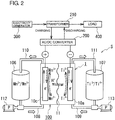
- ions in a positive electrode tank 106 and a negative electrode tank 107 are examples of ionic species contained in a positive electrode electrolyte and a negative electrode electrolyte.
- the solid arrow indicates charging, and the dashed arrow indicates discharging.
- the RF battery system S includes the RF battery 1, which includes a positive electrode 10c and a negative electrode 10a, a positive electrode electrolyte to be supplied to the positive electrode 10c, and a negative electrode electrolyte to be supplied to the negative electrode 10a.
- the RF battery system S further includes a circulation mechanism described later, which supplies the electrolytes to the electrodes 10.
- the RF battery 1 is coupled to an electricity generator 300 and a load 400, such as an electric power system or customer, via an AC/DC converter 200 and a transformer 210.
- the RF battery 1 performs charging using the electricity generator 300 as an electricity supply source and performs discharging to the load 400, which is a power supply target.
- the electricity generator 300 is a photovoltaic generator, a wind power generator, or a general power plant.
- the RF battery 1 includes a battery cell 100 as a main component.
- the battery cell 100 includes the positive electrode 10c, the negative electrode 10a, and a membrane 11 between the positive electrode 10c and the negative electrode 10a.
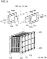
- the RF battery 1 includes a plurality of the battery cells 100 with a bipolar plate 12 interposed between adjacent battery cells 100 and 100 ( Fig. 3 ).
- the electrodes 10 are reaction fields where active material ions undergo a cell reaction and are formed of a porous body through which an electrolyte can flow.
- the RF battery electrode according to the first embodiment is composed of a porous body formed of a carbon material.
- the carbon material has a specific crystal structure (described in detail later).
- the positive electrode 10c is the electrode according to the first embodiment.
- the membrane 11 is a separating member for separating the positive electrode 10c from the negative electrode 10a and is a member through which specified ions can pass.
- the bipolar plate 12 is a flat member between the positive electrode 10c and the negative electrode 10a and is an electrically conductive member that can carry an electric current but is impervious to an electrolyte.
- the bipolar plate 12 is used in the form of a frame assembly 15 that includes a frame 150 on the periphery of the bipolar plate 12.
- the frame 150 has an opening on its front and back surfaces and has supply holes 152c and 152a for supplying an electrolyte to the electrodes 10 and drain holes 154c and 154a for draining the electrolyte disposed on the bipolar plate 12.
- the battery cells 100 are stacked and used in the form of a cell stack.
- the cell stack is constructed by repeatedly stacking the bipolar plate 12 of one frame assembly 15, the positive electrode 10c, the membrane 11, the negative electrode 10a, and the bipolar plate 12 of the other frame assembly 15.
- a predetermined number of the battery cells 100 are stacked to form a subcell stack, and a plurality of the subcell stacks are stacked to form a cell stack.
- Figure 3 illustrates the cell stack composed of subcell stacks.
- a current collector (not shown) is disposed on the electrode 10 at each end of the subcell stack or cell stack in the stacking direction of the battery cells 100.
- an end plate 170 is disposed at each end of the cell stack in the stacking direction of the battery cells 100, and the pair of end plates 170 and 170 are joined with a coupling member 172, such as long bolts.
- the circulation mechanism includes the positive electrode tank 106 for storing a positive electrode electrolyte circulated and supplied to the positive electrode 10c, the negative electrode tank 107 for storing a negative electrode electrolyte circulated and supplied to the negative electrode 10a, pipes 108 and 110 between the positive electrode tank 106 and the RF battery 1, pipes 109 and 111 between the negative electrode tank 107 and the RF battery 1, and pumps 112 and 113 on the pipes 108 and 109 on the upstream (supply) side.
- the supply holes 152c and 152a and the drain holes 154c and 154a in the stacked frame assemblies 15 constitute an electrolyte flow path to which the pipes 108 to 111 are coupled.
- the RF battery system S circulates and supplies a positive electrode electrolyte to the positive electrode 10c through a positive electrode electrolyte circulation path including the positive electrode tank 106 and the pipes 108 and 110 and circulates and supplies a negative electrode electrolyte to the negative electrode 10a through a negative electrode electrolyte circulation path including the negative electrode tank 107 and the pipes 109 and 111.
- charging and discharging are performed in association with a valence change reaction of active material ions in the positive electrode electrolyte and the negative electrode electrolyte.
- the positive electrode electrolyte contains specific ions (described in detail later).
- the electrodes 10 are formed of a porous body with open pores.
- the porous body is formed of a carbon material.
- the carbon content of the carbon material is 99% or more by mass, and the remainder is composed of gas components described later, incidental impurities, etc.
- the incidental impurity content of the carbon material is preferably 1000 ppm or less by mass.
- the carbon material of the porous body may be carbon fiber or a carbon powder. Carbon materials have high electrical conductivity, chemical resistance, and oxidation resistance.
- a porous body formed of a carbon material is suitable for the electrodes 10 according to the first embodiment, which require high electrical conductivity and resistance to an electrolyte.
- the carbon fiber has a size (fiber diameter) in the range of approximately 1 to 10 ⁇ m, for example.
- porous body formed of a carbon material examples include sheet-like fiber assemblies composed of carbon fibers, such as carbon felt, carbon paper, and carbon cloth.
- Carbon felt has advantages of (a) little evolution of oxygen gas even at the oxygen evolution potential during a charging process in an aqueous electrolyte, (b) a large surface area, and (c) a high electrolyte flow rate.
- Carbon paper has advantages of ( ⁇ ) easily providing a small thin battery and ( ⁇ ) high electrical conductivity in the thickness direction.
- the positive electrode 10c and the negative electrode 10a in this embodiment are fiber assembly sheets.
- the porous body is formed of a carbon material with a specific crystal structure. More specifically, the (002) plane of the carbon material has an interlayer distance d (002) in the range of 3.354 to 3.452 angstroms as measured by X-ray diffraction.
- the positive electrode 10c in the RF battery system S according to the first embodiment is the electrode according to the first embodiment composed of the porous body formed of the carbon material with the specific crystal structure.
- the electrode according to the first embodiment is formed of the carbon material with an interlayer distance d (002) of 3.354 angstroms or more.
- the RF battery 1 or the RF battery system S with the electrode does not have an excessively high initial resistivity and has low resistance.
- the initial resistivity decreases with increasing interlayer distance d (002) .
- the interlayer distance d (002) is preferably 3.358 angstroms or more, more preferably 3.38 angstroms or more, still more preferably 3.40 angstroms or more.
- the electrode according to the first embodiment is formed of the carbon material with an interlayer distance d (002) of 3.452 angstroms or less.
- the RF battery 1 or the RF battery system S with the electrode can have a smaller increase in resistivity over time and can have low resistance for extended periods from the beginning of operation. This is because the electrode according to the first embodiment is resistant to oxidative degradation over time and can reduce the decrease in reaction fields due to degradation, such as oxidative degradation.
- the increase in resistivity over time decreases with decreasing interlayer distance d (002) .
- the interlayer distance d (002) is preferably 3.45 angstroms or less, more preferably 3.445 angstroms or less, still more preferably 3.44 angstroms or less.
- the interlayer distance d (002) can be measured with a known X-ray diffractometer. The measurement conditions will be described in detail later.
- the carbon material with an interlayer distance d (002) in the range described above typically has a graphite crystal structure or a quasi-graphite crystal structure.
- the porous body formed of such a carbon material is a porous body formed of a high-temperature-treated carbon material carbonized at a high temperature of approximately 1200°C to 1800°C, or 1800°C or more (for example, 2000°C or more).
- a greater interlayer distance d (002) results in the RF battery 1 or the RF battery system S with lower resistance.
- the present inventors have found that an electrode with a trace amount of oxygen in a specific range on the carbon material surface can decrease the initial resistivity even when the interlayer distance d (002) is somewhat small.
- carbon materials are hydrophobic, and electrodes formed of carbon materials are less hydrophilic.
- a specific amount of oxygen on the carbon material surface can probably increase hydrophilicity to an electrolyte. High hydrophilicity enables an electrolyte to permeate into every corner of an electrode and ensures a sufficient reaction field, thereby decreasing initial resistivity.
- the electrode according to the first embodiment preferably has an oxygen content in a specific range. More specifically, the oxygen content preferably ranges from 1 to 100 ⁇ mol/g.
- oxygen content refers to the content measured by temperature programmed desorption/mass spectrometry (TPD-MS) and refers to the total amount of oxygen in carbon monoxide (CO) and carbon dioxide (CO 2 ) evolved from a sample.
- TPD-MS temperature programmed desorption/mass spectrometry
- CO carbon monoxide
- CO 2 carbon dioxide
- the total amount of oxygen is herein referred to as the oxygen content derived from CO and CO 2 .
- the oxygen content derived from CO and CO 2 can be measured with a known TPD-MS apparatus. The measurement conditions will be described in detail later.
- An electrode with an oxygen content derived from CO and CO 2 of 1 ⁇ mol/g or more has high hydrophilicity to an electrolyte.
- the RF battery 1 or the RF battery system S with such an electrode can have a low initial resistivity.
- a higher oxygen content derived from CO and CO 2 results in higher hydrophilicity.
- the oxygen content derived from CO and CO 2 is preferably 5 ⁇ mol/g or more, more preferably 10 ⁇ mol/g or more.
- An electrode with an oxygen content derived from CO and CO 2 of 100 ⁇ mol/g or less has no excess oxygen on its surface and can reduce the decrease in electrical conductivity due to excess oxygen.
- the RF battery 1 or the RF battery system S with such an electrode can have a low initial resistivity.
- a lower oxygen content derived from CO and CO 2 results in a smaller decrease in electrical conductivity.
- the oxygen content derived from CO and CO 2 is preferably 80 ⁇ mol/g or less, more preferably 60 ⁇ mol/g or less.
- the RF battery 1 or the RF battery system S including an electrode with an oxygen content derived from CO and CO 2 in this specific range can have a resistance as low as initial resistivity for extended periods from the beginning of operation.
- TPD-MS Even when a sample is temporarily immersed in water or an acid, such as sulfuric acid, TPD-MS is not significantly affected by water or the acid and can accurately measure oxygen in the sample. Thus, the measurement of the oxygen content derived from CO and CO 2 by TPD-MS can be accurate in an electrode impregnated with an electrolyte in the RF battery system S, as well as in an electrode not impregnated with an electrolyte before installed in the RF battery 1.
- the electrode according to the first embodiment has an interlayer distance d (002) in the specific range.
- the RF battery 1 with the electrode can have a low initial resistivity.
- the RF battery 1 with the electrode according to the first embodiment has an initial resistivity of 1.8 ⁇ cm or less, for example.
- a lower initial resistivity results in the RF battery 1 or the RF battery system S with higher cell reactivity.
- the initial resistivity is preferably 1.6 ⁇ cm 2 or less, more preferably 1.5 ⁇ cm 2 or less.
- the electrode according to the first embodiment can be produced by a known method that is used for the production of a porous body formed of a carbon material.
- a carbon-containing material containing a carbon element (C) is used as a raw material, and the raw material can be carbonized and then subjected to dry oxidation treatment, thus producing a porous body formed of a carbon material.
- the carbon-containing material may be polyacrylonitrile, pitch, or rayon.
- the conditions for carbonization treatment include heating in an atmosphere of an inert gas, such as argon, or in a nitrogen atmosphere at a temperature of more than 1800°C, 1900°C or more, or 2000°C or more.
- a heating temperature of more than 1800°C can result in a relatively small interlayer distance d (002) , as described above.
- the conditions for dry oxidation treatment include heating in the air at a temperature in the range of approximately 400°C to 800°C, for example.
- the negative electrode 10a may be a known electrode.
- the negative electrode 10a is an electrode other than the electrode according to the first embodiment, for example, an electrode composed of a porous body formed of a carbon material with an interlayer distance d (002) of more than 3.452 angstroms, the initial resistivity can be more easily decreased.
- Both the positive electrode 10c and the negative electrode 10a may be the electrode according to the first embodiment.
- the RF battery system S includes the electrolytes.
- the electrolytes contain metal ions or non-metal ions as ions serving as an active material and are supplied to the electrodes 10.
- the electrolytes of the RF battery system S are V electrolytes containing vanadium (V) ions with different valences as the positive-electrode active material and the negative-electrode active material.
- the RF battery system S according to the first embodiment includes a positive electrode electrolyte, which contains at least one type of ions selected from chloride ions, manganese ions, bromine ions, and cerium ions as a positive-electrode active material.
- These ions have a standard oxidation-reduction potential higher than the standard oxidation-reduction potential of vanadium ions (1.0 V).
- Chloride ions have a standard oxidation-reduction potential of approximately 1.3 V
- manganese ions have a standard oxidation-reduction potential of approximately 1.5 V
- bromine ions have a standard oxidation-reduction potential of approximately 1.05 V
- cerium ions have a standard oxidation-reduction potential of approximately 1.8 V.
- the RF battery system S according to the first embodiment has a high electromotive force.
- the positive electrode electrolyte can contain only one type of ions out of the four types of ions in one embodiment or two or more types of ions in another embodiment.
- the latter embodiment which contains ions with a noble potential and ions with a less-noble potential, can increase the utilization of the active material and improve the energy density.
- the concentration of the positive-electrode active material ions in the positive electrode electrolyte (the total concentration in the case of a plurality of types of ions) ranges from approximately 0.3 to 5 M, for example.
- the ion concentration "M" refers to the molar concentration (mol/liter). The same applies hereinafter.
- the positive electrode electrolyte preferably contains manganese ions as a positive-electrode active material, because the RF battery system S containing the positive electrode electrolyte can have a higher electromotive force than V RF batteries.
- the positive electrode electrolyte more preferably contains titanium ions in addition to manganese ions, because titanium ions can reduce the precipitation of manganese oxide and stabilize an oxidation-reduction reaction of manganese ions.
- the concentration of titanium ions in the positive electrode electrolyte ranges from approximately 0.3 to 2 M, for example.
- the negative-electrode active material is at least one type of ions selected from titanium ions, vanadium ions, and chromium ions. These three types of ions, together with the four types of ions described above as the positive-electrode active material, can form a redox pair with a high electromotive force.
- the RF battery system S with the electrolyte containing such a redox pair has a high electromotive force.
- the negative electrode electrolyte can contain only one type of ions out of the three types of ions in one embodiment or two or more types of ions in another embodiment.
- the latter embodiment can increase the utilization of the active material and improve the energy density, as described above.
- the concentration of the active material ions in the negative electrode electrolyte (the total concentration in the case of a plurality of types of ions) ranges from approximately 0.3 to 5 M, for example.
- a Mn-Ti RF battery which includes a positive electrode electrolyte containing manganese ions as a positive-electrode active material and a negative electrode electrolyte containing titanium ions as a negative-electrode active material, has an electromotive force of approximately 1.4 V and is therefore preferred.
- titanium ions in the negative electrode electrolyte move to the positive electrode electrolyte over time and are expected to reduce the precipitation of manganese oxide.
- Each of the positive electrode electrolyte and the negative electrode electrolyte can contain both manganese ions and titanium ions in one embodiment, and particularly the positive electrode electrolyte and the negative electrode electrolyte can have the same composition.
- This embodiment has advantages of (1) easily avoiding the decrease in battery capacity due to the decrease in the amount of active material over time, (2) easily reducing variations in the volumes of the positive electrode electrolyte and the negative electrode electrolyte caused by liquid transfer, (3) easily reducing variations in concentration caused by the transfer of manganese ions and titanium ions to counter electrodes, and (4) the ease of manufacture of the electrolytes.
- the ions in the positive electrode electrolyte and the negative electrode electrolyte are water-soluble ions.
- the positive electrode electrolyte and the negative electrode electrolyte can be an aqueous solution containing water as a solvent.
- the positive electrode electrolyte and the negative electrode electrolyte can be an aqueous solution containing at least one acid selected from sulfuric acid, phosphoric acid, nitric acid, and hydrochloric acid.
- the electrolyte containing such an aqueous solution of an acid can be easily produced by dissolving a salt of an acid in water as a raw material for the active material.
- the bipolar plate 12 is composed of an electrically conductive material that has low electrical resistance, that does not react with an electrolyte, and that is resistant to the electrolyte (chemical resistance, acid resistance, etc.), typically an electrically conductive material that contains a carbon material.
- an electrically conductive material that contains a carbon material typically an electrically conductive material that contains a carbon material.
- a composite material containing a carbon material and an organic material can be used.
- an electrically conductive plastic containing an electrically conductive inorganic material (powder, fiber, etc.), such as graphite, and an organic material, such as a polyolefin organic compound or a chlorinated organic compound, formed into a plate can be used.
- the frame 150 is constituted by an electrically insulating resin that is resistant to an electrolyte.
- the membrane 11 is an ion-exchange membrane, such as a cation-exchange membrane or an anion-exchange membrane.
- Ion-exchange membranes are characteristically excellent in (1) separation of ions of the positive-electrode active material from ions of the negative-electrode active material and (2) permeability of the charge carrier H + ions in the battery cell 100, and are suitable for the membrane 11.
- the membrane 11 can be a known membrane.
- the electrode according to the first embodiment is composed of a porous body formed of a carbon material with a specific crystal structure.
- the electrode used as a component of the RF battery 1, particularly as the positive electrode 10c, can therefore reduce the increase in resistivity over time.
- the RF battery 1 or the RF battery system S with the electrode according to the first embodiment is less likely to deteriorate and can have good characteristics for extended periods.
- the RF battery system S according to the first embodiment includes the electrode according to the first embodiment as the positive electrode 10c, and the positive electrode 10c is resistant to oxidative degradation over time, thus reducing the increase in resistivity due to the degradation of the electrodes 10.
- the RF battery system S according to the first embodiment can have good characteristics for extended periods.
- Porous bodies formed of various carbon materials were checked for the crystal structure of the carbon materials by X-ray diffraction.
- the oxygen contents of the porous bodies were measured by TDP-MS.
- An RF battery system including each of the porous bodies as an electrode was checked for resistivity change over time.
- electrodes A to D porous bodies formed of four types of carbon materials were prepared, and electrodes composed of the porous bodies are referred to as electrodes A to D.
- the electrodes were produced by carbonization treatment and subsequent dry oxidation treatment of a carbon-containing material, such as polyacrylonitrile, under the following different treatment conditions.
- the electrode D is a known electrode.
- the carbonization treatment conditions include a heating temperature of 2000°C or more in the electrodes A and B and 1800°C or less in the electrodes C and D.
- the dry oxidation treatment conditions are known conditions in the electrode B.
- the dry oxidation treatment in the electrode A was a heat treatment in the air at 500°C for 1 hour.
- the electrode C is the electrode D subjected to dry oxidation treatment under the conditions of the electrode A.
- the heating rate from room temperature (approximately 20°C to 25°C) to 1000°C was 10°C/min.
- the electrodes are formed of a high-temperature treated carbon material and have a quasi-graphite crystal structure.
- a technique described in " A quantitative analysis of carbon edge sites and an estimation of graphene sheet size in high-temperature treated, non-porous carbons", Carbon, Volume 80, December 2014, pp. 135-145 can be referred to for the measurement of the oxygen content.
- the positive electrode and the negative electrode of the RF batteries had an electrode area of 9 cm 2 .
- the RF batteries included a membrane Nafion (registered trademark) N212.
- Each of the positive electrode electrolyte and the negative electrode electrolyte was an aqueous sulfuric acid solution containing manganese ions and titanium ions.
- the raw materials for the electrolytes were manganese sulfate, titanium sulfate, and sulfuric acid.
- the concentration of titanium (Ti) ions was 1 M
- the concentration of manganese (Mn) ions was 1 M
- the concentration of sulfur (S) ions was 5 M.
- the sulfur (S) ions include sulfate ions.
- the electrolyte flow rate was 5.4 milliliter/min., and the amount of each of the positive electrode electrolyte and the negative electrode electrolyte was 15 milliliter.
- the final discharge voltage was 1 V, and the final charge voltage was 1.5 V.
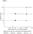
- Electrode A 3.44 25 1.3 1.31 0.01 1-2 Electrode B 3.44 0.5 1.8 1.81 0.01 1-3 Electrode C 3.46 25 1.3 1.8 0.5 1-4 Electrode D 3.46 0.5 1.8 2.3 0.5
- the horizontal axis is the interlayer distance d (002) (angstroms) of the carbon material, and the vertical axis is resistivity ( ⁇ cm 2 ).
- the initial resistivity of each sample is represented by a solid symbol, and the resistivity after a predetermined time is represented by an open symbol.
- Table 1 and Fig. 1 show that a shorter interlayer distance d (002) of the carbon material in the electrode can result in a smaller increase in the resistivity of the RF battery over time.
- An interlayer distance d (002) of less than 3.46 angstroms results in a resistivity increase of less than 0.5 ⁇ cm 2 over time.
- the results of the sample Nos. 1-1 and 1-2 show that an interlayer distance d (002) of approximately 3.44 angstroms or less results in a very small resistivity increase of 0.01 ⁇ cm 2 or less over time.
- the resistivity increase over time is preferably smaller. More specifically, the resistivity increase over time is preferably 0.3 ⁇ cm 2 or less, more preferably 0.2 ⁇ cm 2 or less.
- the interlayer distance d (002) is preferably 3.452 angstroms or less in order to achieve a resistivity increase of 0.3 ⁇ cm 2 or less over time
- the interlayer distance d (002) is preferably 3.448 angstroms or less in order to achieve a resistivity increase of 0.2 ⁇ cm 2 or less over time.
- an excessively short interlayer distance d (002) results in an excessively high initial resistivity.
- the interlayer distance d (002) is preferably 3.354 angstroms or more, more preferably 3.40 angstroms or more.
- Table 1 and Fig. 1 also show that even when the interlayer distance d (002) is somewhat small, an interlayer distance d (002) in a specific range can result in a low initial resistivity.
- the results of the sample Nos. 1-1 and 1-2 show that even an interlayer distance d (002) of less than 3.46 angstroms results in an initial resistivity of less than 2 ⁇ cm 2 .
- the RF battery systems of the sample Nos. 1-1 and 1-2 which have a small resistivity increase over time, a low initial resistivity, and a low resistivity after a predetermined time, have good characteristics for extended periods.
- Table 1 shows that even with the same interlayer distance d (002) , a higher oxygen content derived from CO and CO 2 can result in a lower initial resistivity.
- the initial resistivity can be decreased. This is partly because the presence of an appropriate amount of oxygen on the surface of the carbon material in the electrode can increase hydrophilicity to the electrolyte on the electrode, thereby providing the electrode with high electrical conductivity and reactivity.
- the oxygen content derived from CO and CO 2 is preferably 1 ⁇ mol/g or more.
- an excessively high oxygen content derived from CO and CO 2 results in a low electrical conductivity and a high initial resistivity due to excess oxygen.
- the oxygen content derived from CO and CO 2 is preferably 100 ⁇ mol/g or less.
- an RF battery or an RF battery system with a smaller increase in resistivity over time can be produced by using an RF battery electrode composed of a porous body formed of a carbon material with a specific crystal structure. Furthermore, an RF battery system with a smaller increase in resistivity over time and with good characteristics for extended periods can be produced by using such an electrode as a positive electrode even when a Mn-Ti electrolyte is used.
Landscapes
- Chemical & Material Sciences (AREA)
- Chemical Kinetics & Catalysis (AREA)
- Electrochemistry (AREA)
- General Chemical & Material Sciences (AREA)
- Engineering & Computer Science (AREA)
- Life Sciences & Earth Sciences (AREA)
- Manufacturing & Machinery (AREA)
- Sustainable Development (AREA)
- Sustainable Energy (AREA)
- Materials Engineering (AREA)
- Fuel Cell (AREA)
- Inert Electrodes (AREA)
Applications Claiming Priority (2)
| Application Number | Priority Date | Filing Date | Title |
|---|---|---|---|
| JP2015138024 | 2015-07-09 | ||
| PCT/JP2016/067865 WO2017006729A1 (ja) | 2015-07-09 | 2016-06-16 | レドックスフロー電池用電極、及びレドックスフロー電池システム |
Publications (2)
| Publication Number | Publication Date |
|---|---|
| EP3322011A1 true EP3322011A1 (de) | 2018-05-16 |
| EP3322011A4 EP3322011A4 (de) | 2018-06-06 |
Family
ID=57686175
Family Applications (1)
| Application Number | Title | Priority Date | Filing Date |
|---|---|---|---|
| EP16821199.3A Withdrawn EP3322011A4 (de) | 2015-07-09 | 2016-06-16 | Elektrode für redox-flussbatterie und redox-flussbatteriesystem |
Country Status (8)
| Country | Link |
|---|---|
| US (1) | US20180190991A1 (de) |
| EP (1) | EP3322011A4 (de) |
| JP (1) | JPWO2017006729A1 (de) |
| KR (1) | KR20180027428A (de) |
| CN (1) | CN107710479A (de) |
| AU (1) | AU2016288963A1 (de) |
| TW (1) | TW201703328A (de) |
| WO (1) | WO2017006729A1 (de) |
Cited By (1)
| Publication number | Priority date | Publication date | Assignee | Title |
|---|---|---|---|---|
| WO2020174062A1 (en) * | 2019-02-28 | 2020-09-03 | Ip2Ipo Innovations Limited | Redox flow cell |
Families Citing this family (4)
| Publication number | Priority date | Publication date | Assignee | Title |
|---|---|---|---|---|
| US11217808B2 (en) * | 2017-11-07 | 2022-01-04 | Sumitomo Electric Industries, Ltd. | Raw material of electrolyte solution, method for manufacturing electrolyte solution and method for manufacturing redox flow battery |
| JP7226443B2 (ja) * | 2018-06-12 | 2023-02-21 | 住友電気工業株式会社 | レドックスフロー電池用電極、及びレドックスフロー電池 |
| KR102144571B1 (ko) * | 2018-10-24 | 2020-08-14 | 울산과학기술원 | 전극 구조체, 이의 제조 방법 및 이를 포함하는 이차 전지 |
| CN114156514B (zh) * | 2020-09-08 | 2023-11-21 | 中国科学院大连化学物理研究所 | 一种液流电池电解液及其应用 |
Family Cites Families (11)
| Publication number | Priority date | Publication date | Assignee | Title |
|---|---|---|---|---|
| JPH05234612A (ja) * | 1992-02-21 | 1993-09-10 | Toyobo Co Ltd | 電解槽用炭素電極材 |
| JP3496385B2 (ja) * | 1995-02-16 | 2004-02-09 | 住友電気工業株式会社 | レドックス電池 |
| JPH0992321A (ja) * | 1995-09-27 | 1997-04-04 | Kashimakita Kyodo Hatsuden Kk | レドックス電池 |
| JP3601581B2 (ja) * | 1999-06-11 | 2004-12-15 | 東洋紡績株式会社 | バナジウム系レドックスフロー電池用炭素電極材 |
| JP2001085022A (ja) * | 1999-09-10 | 2001-03-30 | Toyobo Co Ltd | 炭素電極材及び炭素電極材集合体 |
| JP4674883B2 (ja) * | 2000-02-09 | 2011-04-20 | 日立マクセル株式会社 | ポリ硫化カーボン、その製造方法およびそれを用いた非水電解質電池 |
| US6709787B2 (en) * | 2000-02-09 | 2004-03-23 | Hitachi Maxell, Ltd. | Polycarbon sulfide, process for preparing the same and nonaqueous electrolyte battery comprising the same |
| JP5712688B2 (ja) * | 2010-03-12 | 2015-05-07 | 住友電気工業株式会社 | レドックスフロー電池 |
| CN103620845B (zh) * | 2011-06-27 | 2016-10-05 | 住友电气工业株式会社 | 氧化还原液流电池 |
| JP5769070B2 (ja) * | 2011-06-27 | 2015-08-26 | 住友電気工業株式会社 | レドックスフロー電池 |
| AU2014303614B2 (en) * | 2013-08-07 | 2017-09-14 | Sumitomo Electric Industries, Ltd. | Redox flow battery |
-
2016
- 2016-06-16 CN CN201680036837.9A patent/CN107710479A/zh active Pending
- 2016-06-16 EP EP16821199.3A patent/EP3322011A4/de not_active Withdrawn
- 2016-06-16 JP JP2017527154A patent/JPWO2017006729A1/ja active Pending
- 2016-06-16 AU AU2016288963A patent/AU2016288963A1/en not_active Abandoned
- 2016-06-16 WO PCT/JP2016/067865 patent/WO2017006729A1/ja not_active Ceased
- 2016-06-16 KR KR1020177035647A patent/KR20180027428A/ko not_active Withdrawn
- 2016-06-16 US US15/738,717 patent/US20180190991A1/en not_active Abandoned
- 2016-06-21 TW TW105119445A patent/TW201703328A/zh unknown
Cited By (3)
| Publication number | Priority date | Publication date | Assignee | Title |
|---|---|---|---|---|
| WO2020174062A1 (en) * | 2019-02-28 | 2020-09-03 | Ip2Ipo Innovations Limited | Redox flow cell |
| US12191545B2 (en) | 2019-02-28 | 2025-01-07 | Ip2Ipo Innovations Limited | Redox flow cell |
| AU2020228137B2 (en) * | 2019-02-28 | 2025-12-18 | Ip2Ipo Innovations Limited | Redox flow cell |
Also Published As
| Publication number | Publication date |
|---|---|
| CN107710479A (zh) | 2018-02-16 |
| WO2017006729A1 (ja) | 2017-01-12 |
| US20180190991A1 (en) | 2018-07-05 |
| TW201703328A (zh) | 2017-01-16 |
| KR20180027428A (ko) | 2018-03-14 |
| AU2016288963A1 (en) | 2018-01-04 |
| JPWO2017006729A1 (ja) | 2018-04-19 |
| EP3322011A4 (de) | 2018-06-06 |
Similar Documents
| Publication | Publication Date | Title |
|---|---|---|
| Ling et al. | Porous composite membrane of PVDF/Sulfonic silica with high ion selectivity for vanadium redox flow battery | |
| Pahlevaninezhad et al. | Effects of aluminum, iron, and manganese sulfate impurities on the vanadium redox flow battery | |
| US10673090B2 (en) | All-vanadium sulfate acid redox flow battery system | |
| US20160293963A1 (en) | Oxygen-vanadium redox flow battery with vanadium electrolyte having carbon particles dispersed therein | |
| EP3322011A1 (de) | Elektrode für redox-flussbatterie und redox-flussbatteriesystem | |
| Langner et al. | Determination of overpotentials in all vanadium redox flow batteries | |
| JP6599991B2 (ja) | 高分子電解質膜、これを含む電気化学電池及びフロー電池、高分子電解質膜の製造方法、及びフロー電池用電解液 | |
| EP3327839A1 (de) | Redox-durchflussbatterieelektrode, redox-durchfluss-batterie und verfahren zur beurteilung von elektrodeneigenschaften | |
| Park et al. | Development of a redox flow battery with multiple redox couples at both positive and negative electrolytes for high energy density | |
| JP5864682B2 (ja) | ペースト状バナジウム電解質の製造方法及びバナジウムレドックス電池の製造方法 | |
| US20170244127A1 (en) | Impact of membrane characteristics on the performance and cycling of the br2-h2 redox flow cell | |
| EP3579250B1 (de) | Polymerelektrolytmembran, elektrochemische zelle damit und durchflusszelle damit, zusammensetzung für polymerelektrolytmembranen und verfahren zur herstellung von polymerelektrolytmembranen | |
| Noack et al. | A comparison of materials and treatment of materials for vanadium redox flow battery | |
| Wang et al. | High-efficient multifunctional electrochemical membrane for lithium polysulfide redox flow batteries | |
| EP2800181A1 (de) | Verwendung einer protonenaustauschmembran in einer eisen-chrom-flüssigkeitsbatterie | |
| EP4002532A1 (de) | Redox-durchflusszelle, zellenstapel und redoxstrombatteriesystem | |
| EP3627604B1 (de) | Ionenaustauschtrennmembran und flussbatterie damit | |
| EP2800167A1 (de) | Verwendung einer anionen-protonenaustauschmembrans in einer eisen-chrom-flüssigkeitsbatterie | |
| CN114503313A (zh) | 电极、电池单体、电池堆及氧化还原液流电池系统 | |
| Yasuda et al. | The effects of contaminants of fuel on the direct methanol fuel cell (DMFC) performance | |
| KR20130092032A (ko) | 레독스 플로우 이차 전지 | |
| TWI699927B (zh) | 氧化還原液流電池、氧化還原液流電池用電極及電極之特性評估方法 | |
| EP4002531A1 (de) | Redox-durchflussbatteriezelle, zellenstapel und redox-durchflussbatteriesystem | |
| Kim et al. | Performance Comparision of Sulfonated Polyimide/PTFE-Reinforced Membranes for ZnBr Flow Batteries |
Legal Events
| Date | Code | Title | Description |
|---|---|---|---|
| STAA | Information on the status of an ep patent application or granted ep patent |
Free format text: STATUS: THE INTERNATIONAL PUBLICATION HAS BEEN MADE |
|
| PUAI | Public reference made under article 153(3) epc to a published international application that has entered the european phase |
Free format text: ORIGINAL CODE: 0009012 |
|
| STAA | Information on the status of an ep patent application or granted ep patent |
Free format text: STATUS: REQUEST FOR EXAMINATION WAS MADE |
|
| 17P | Request for examination filed |
Effective date: 20171220 |
|
| AK | Designated contracting states |
Kind code of ref document: A1 Designated state(s): AL AT BE BG CH CY CZ DE DK EE ES FI FR GB GR HR HU IE IS IT LI LT LU LV MC MK MT NL NO PL PT RO RS SE SI SK SM TR |
|
| AX | Request for extension of the european patent |
Extension state: BA ME |
|
| A4 | Supplementary search report drawn up and despatched |
Effective date: 20180507 |
|
| RIC1 | Information provided on ipc code assigned before grant |
Ipc: H01M 8/18 20060101ALI20180430BHEP Ipc: H01M 4/96 20060101AFI20180430BHEP Ipc: H01M 8/02 20160101ALI20180430BHEP |
|
| DAV | Request for validation of the european patent (deleted) | ||
| DAX | Request for extension of the european patent (deleted) | ||
| STAA | Information on the status of an ep patent application or granted ep patent |
Free format text: STATUS: THE APPLICATION IS DEEMED TO BE WITHDRAWN |
|
| 18D | Application deemed to be withdrawn |
Effective date: 20181205 |