EP4043244B1 - Luftreifen - Google Patents
Luftreifen Download PDFInfo
- Publication number
- EP4043244B1 EP4043244B1 EP20897396.6A EP20897396A EP4043244B1 EP 4043244 B1 EP4043244 B1 EP 4043244B1 EP 20897396 A EP20897396 A EP 20897396A EP 4043244 B1 EP4043244 B1 EP 4043244B1
- Authority
- EP
- European Patent Office
- Prior art keywords
- widthwise
- tire
- sipe
- region
- pneumatic tire
- Prior art date
- Legal status (The legal status is an assumption and is not a legal conclusion. Google has not performed a legal analysis and makes no representation as to the accuracy of the status listed.)
- Active
Links
Images

Classifications
-
- B—PERFORMING OPERATIONS; TRANSPORTING
- B60—VEHICLES IN GENERAL
- B60C—VEHICLE TYRES; TYRE INFLATION; TYRE CHANGING; CONNECTING VALVES TO INFLATABLE ELASTIC BODIES IN GENERAL; DEVICES OR ARRANGEMENTS RELATED TO TYRES
- B60C11/00—Tyre tread bands; Tread patterns; Anti-skid inserts
- B60C11/03—Tread patterns
- B60C11/11—Tread patterns in which the raised area of the pattern consists only of isolated elements, e.g. blocks
-
- B—PERFORMING OPERATIONS; TRANSPORTING
- B60—VEHICLES IN GENERAL
- B60C—VEHICLE TYRES; TYRE INFLATION; TYRE CHANGING; CONNECTING VALVES TO INFLATABLE ELASTIC BODIES IN GENERAL; DEVICES OR ARRANGEMENTS RELATED TO TYRES
- B60C11/00—Tyre tread bands; Tread patterns; Anti-skid inserts
- B60C11/0041—Tyre tread bands; Tread patterns; Anti-skid inserts comprising different tread rubber layers
- B60C11/005—Tyre tread bands; Tread patterns; Anti-skid inserts comprising different tread rubber layers with cap and base layers
-
- B—PERFORMING OPERATIONS; TRANSPORTING
- B60—VEHICLES IN GENERAL
- B60C—VEHICLE TYRES; TYRE INFLATION; TYRE CHANGING; CONNECTING VALVES TO INFLATABLE ELASTIC BODIES IN GENERAL; DEVICES OR ARRANGEMENTS RELATED TO TYRES
- B60C11/00—Tyre tread bands; Tread patterns; Anti-skid inserts
- B60C11/0008—Tyre tread bands; Tread patterns; Anti-skid inserts characterised by the tread rubber
-
- B—PERFORMING OPERATIONS; TRANSPORTING
- B60—VEHICLES IN GENERAL
- B60C—VEHICLE TYRES; TYRE INFLATION; TYRE CHANGING; CONNECTING VALVES TO INFLATABLE ELASTIC BODIES IN GENERAL; DEVICES OR ARRANGEMENTS RELATED TO TYRES
- B60C11/00—Tyre tread bands; Tread patterns; Anti-skid inserts
- B60C11/0041—Tyre tread bands; Tread patterns; Anti-skid inserts comprising different tread rubber layers
-
- B—PERFORMING OPERATIONS; TRANSPORTING
- B60—VEHICLES IN GENERAL
- B60C—VEHICLE TYRES; TYRE INFLATION; TYRE CHANGING; CONNECTING VALVES TO INFLATABLE ELASTIC BODIES IN GENERAL; DEVICES OR ARRANGEMENTS RELATED TO TYRES
- B60C11/00—Tyre tread bands; Tread patterns; Anti-skid inserts
- B60C11/03—Tread patterns
- B60C11/0302—Tread patterns directional pattern, i.e. with main rolling direction
-
- B—PERFORMING OPERATIONS; TRANSPORTING
- B60—VEHICLES IN GENERAL
- B60C—VEHICLE TYRES; TYRE INFLATION; TYRE CHANGING; CONNECTING VALVES TO INFLATABLE ELASTIC BODIES IN GENERAL; DEVICES OR ARRANGEMENTS RELATED TO TYRES
- B60C11/00—Tyre tread bands; Tread patterns; Anti-skid inserts
- B60C11/03—Tread patterns
- B60C11/0306—Patterns comprising block rows or discontinuous ribs
-
- B—PERFORMING OPERATIONS; TRANSPORTING
- B60—VEHICLES IN GENERAL
- B60C—VEHICLE TYRES; TYRE INFLATION; TYRE CHANGING; CONNECTING VALVES TO INFLATABLE ELASTIC BODIES IN GENERAL; DEVICES OR ARRANGEMENTS RELATED TO TYRES
- B60C11/00—Tyre tread bands; Tread patterns; Anti-skid inserts
- B60C11/03—Tread patterns
- B60C11/12—Tread patterns characterised by the use of narrow slits or incisions, e.g. sipes
- B60C11/1236—Tread patterns characterised by the use of narrow slits or incisions, e.g. sipes with special arrangements in the tread pattern
-
- B—PERFORMING OPERATIONS; TRANSPORTING
- B60—VEHICLES IN GENERAL
- B60C—VEHICLE TYRES; TYRE INFLATION; TYRE CHANGING; CONNECTING VALVES TO INFLATABLE ELASTIC BODIES IN GENERAL; DEVICES OR ARRANGEMENTS RELATED TO TYRES
- B60C11/00—Tyre tread bands; Tread patterns; Anti-skid inserts
- B60C11/03—Tread patterns
- B60C11/12—Tread patterns characterised by the use of narrow slits or incisions, e.g. sipes
- B60C11/1272—Width of the sipe
- B60C11/1281—Width of the sipe different within the same sipe, i.e. enlarged width portion at sipe bottom or along its length
-
- B—PERFORMING OPERATIONS; TRANSPORTING
- B60—VEHICLES IN GENERAL
- B60C—VEHICLE TYRES; TYRE INFLATION; TYRE CHANGING; CONNECTING VALVES TO INFLATABLE ELASTIC BODIES IN GENERAL; DEVICES OR ARRANGEMENTS RELATED TO TYRES
- B60C11/00—Tyre tread bands; Tread patterns; Anti-skid inserts
- B60C11/0008—Tyre tread bands; Tread patterns; Anti-skid inserts characterised by the tread rubber
- B60C2011/0016—Physical properties or dimensions
- B60C2011/0025—Modulus or tan delta
-
- B—PERFORMING OPERATIONS; TRANSPORTING
- B60—VEHICLES IN GENERAL
- B60C—VEHICLE TYRES; TYRE INFLATION; TYRE CHANGING; CONNECTING VALVES TO INFLATABLE ELASTIC BODIES IN GENERAL; DEVICES OR ARRANGEMENTS RELATED TO TYRES
- B60C11/00—Tyre tread bands; Tread patterns; Anti-skid inserts
- B60C11/03—Tread patterns
- B60C2011/0337—Tread patterns characterised by particular design features of the pattern
- B60C2011/0339—Grooves
- B60C2011/0341—Circumferential grooves
- B60C2011/0344—Circumferential grooves provided at the equatorial plane
-
- B—PERFORMING OPERATIONS; TRANSPORTING
- B60—VEHICLES IN GENERAL
- B60C—VEHICLE TYRES; TYRE INFLATION; TYRE CHANGING; CONNECTING VALVES TO INFLATABLE ELASTIC BODIES IN GENERAL; DEVICES OR ARRANGEMENTS RELATED TO TYRES
- B60C11/00—Tyre tread bands; Tread patterns; Anti-skid inserts
- B60C11/03—Tread patterns
- B60C11/12—Tread patterns characterised by the use of narrow slits or incisions, e.g. sipes
- B60C11/1204—Tread patterns characterised by the use of narrow slits or incisions, e.g. sipes with special shape of the sipe
- B60C2011/1209—Tread patterns characterised by the use of narrow slits or incisions, e.g. sipes with special shape of the sipe straight at the tread surface
-
- B—PERFORMING OPERATIONS; TRANSPORTING
- B60—VEHICLES IN GENERAL
- B60C—VEHICLE TYRES; TYRE INFLATION; TYRE CHANGING; CONNECTING VALVES TO INFLATABLE ELASTIC BODIES IN GENERAL; DEVICES OR ARRANGEMENTS RELATED TO TYRES
- B60C11/00—Tyre tread bands; Tread patterns; Anti-skid inserts
- B60C11/03—Tread patterns
- B60C11/12—Tread patterns characterised by the use of narrow slits or incisions, e.g. sipes
- B60C11/1236—Tread patterns characterised by the use of narrow slits or incisions, e.g. sipes with special arrangements in the tread pattern
- B60C2011/1254—Tread patterns characterised by the use of narrow slits or incisions, e.g. sipes with special arrangements in the tread pattern with closed sipe, i.e. not extending to a groove
Definitions
- the present invention relates to a pneumatic tire.
- the present disclosure aims to provide a pneumatic tire that achieves both on-ice performance and on-snow performance.
- a pneumatic tire of the present invention includes, on a tread surface, a plurality of circumferential main grooves extending in a tire circumferential direction, and a plurality of land portions defined between circumferential main grooves adjacent in a tire width direction among the plurality of circumferential main grooves or by the circumferential main grooves and tread edges, wherein
- the "tread surface” refers to the entire tread surface in the tire circumferential direction that comes into contact with the road surface when the pneumatic tire is mounted on an applicable rim, filled to a prescribed internal pressure, and subjected to the maximum load.
- the "circumferential main groove” refers to a groove extending in the tire circumferential direction and having an opening width of 1.5 mm or more at the aforementioned tread surface when the pneumatic tire is mounted on an applicable rim, filled to a prescribed internal pressure, and under no load.
- tread edges refer to the outermost points of the aforementioned tread surface on both sides in the tire width direction.
- the "widthwise groove” refers to a groove extending in the tire width direction and having an opening width of 1.0 mm or more at the aforementioned tread surface when the pneumatic tire is mounted on an applicable rim, filled to a prescribed internal pressure, and under no load.
- the "widthwise sipe” refers to a sipe extending in the tire width direction and having an opening width of less than 1.0 mm at the aforementioned tread surface when the pneumatic tire is mounted on an applicable rim, filled to a prescribed internal pressure, and under no load.
- the value (M (modulus) 25) obtained by conducting a tensile test in accordance with JIS K 6251 and measuring the tensile stress at 25% elongation was adopted.
- the "applicable rim” refers to a standard rim of an applicable size, such as the Measuring Rim in the STANDARDS MANUAL of the European Tyre and Rim Technological Organisation (ETRTO) in Europe or the Design Rim in the YEAR BOOK of the Tire and Rim Association, Inc. (TRA) in the USA, that is described, or will be described in the future, in industrial standards effective in the region where the tire is manufactured and used, such as the YEAR BOOK published by the Japan Automobile Tyre Manufacturers Association (JATMA) in Japan, the STANDARDS MANUAL of the ETRTO, and the YEAR BOOK of the TRA.
- ETRTO European Tyre and Rim Technological Organisation
- TRA Design Rim in the YEAR BOOK of the Tire and Rim Association, Inc.
- the rim encompasses not only current sizes but also sizes that may be included in industrial standards in the future.
- An example of the "size that will be described in the future” is the size described under “future developments" in the ETRTO Standards Manual 2013).
- the "rim” refers to a rim whose width corresponds to the bead width of the tire.
- the “prescribed internal pressure” represents the air pressure (maximum air pressure) corresponding to the maximum load capability of a single wheel in an applicable size/ply rating described by the aforementioned JATMA or the like.
- the “prescribed internal pressure” refers to the air pressure (maximum air pressure) corresponding to the maximum load capability prescribed for each vehicle on which the tire is mounted.
- the “maximum load” refers to the load corresponding to the aforementioned maximum load capability.
- the surface roughness Ra refers to the centerline average roughness measured based on JIS B 0601.
- the kurtosis Rku refers to the sharpness of the surface roughness calculated based on ISO 25178.
- a pneumatic tire that achieves both on-ice performance and on-snow performance can be provided.
- the internal structure and the like of the pneumatic tire can be the same as those of conventional tires.
- the tire can have a pair of bead portions, a pair of sidewall portions connected to the pair of bead portions, and a tread portion disposed between the pair of sidewall portions.
- the tire can also have a carcass extending toroidally between the pair of bead portions and a belt disposed on the radially outward side of a crown portion of the carcass.
- the dimensions and the like refer to the dimensions and the like when the tire is mounted on an applicable rim, filled to the prescribed internal pressure, and under no load.
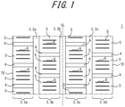
- FIG. 1 is a developed view schematically illustrating a tread pattern of a pneumatic tire according to an embodiment of the present invention.
- the tire in the present example includes, on a tread surface 1, a plurality (three in the illustrated example) of circumferential main grooves 2 (2a, 2b, 2c) extending in the tire circumferential direction, and a plurality (four in the illustrated example) of land portions 3 (3a, 3b, 3c, 3d) defined by circumferential main grooves 2 adjacent in the tire width direction among the plurality of circumferential main grooves 2, or by a circumferential main groove (2a, 2c) and a tread edge TE.
- one circumferential main groove 2b is positioned on the tire equatorial plane CL, and the other circumferential main grooves 2a, 2c are respectively positioned in one half and the other half, in the tire width direction, divided by the tire equatorial plane CL.
- two land portions 3 are arranged in each tire widthwise half.
- the number of circumferential main grooves 2 is three, but the number can be one or two, or can be four or more. Accordingly, the number of land portions 3 can also be two or three, or can be five or more.
- Each land portion 3 includes a plurality of widthwise grooves 4 extending in the tire width direction and is divided into a plurality of blocks 5 by the widthwise grooves 4.
- all of the land portions 3 are divided into blocks 5, but some of the land portions 3 can also be rib-like land portions that are not completely divided by a widthwise groove.
- a land portion 3 divided in the tire circumferential direction by a widthwise sipe is still considered to be a rib-like land portion as long as the land portion 3 is not completely divided by a widthwise groove.
- widthwise sipes 6 a plurality of widthwise sipes 6 (three in each block 5 in the illustrated example) extending in the tire width direction are provided in each block 5, as illustrated in FIG. 1 . It suffices for one or more widthwise sipes 6 to be provided, and hence the number of widthwise sipes 6 can instead be one or two, or four or more.
- the groove width (opening width (opening width measured perpendicular to the extending direction of the groove in plan view)) of the circumferential main groove 2 is not particularly limited, since the groove width also depends on the number of circumferential main grooves 2, but can, for example, be between 5 mm and 25 mm.
- the groove depth (maximum depth) of the circumferential main groove 2 is not particularly limited, but can, for example, be between 6 mm and 18 mm.
- the circumferential main grooves 2 all extend along the tire circumferential direction (without inclination) in plan view of the tread surface 1, but at least one of the circumferential main grooves 2 may extend at an inclination relative to the tire circumferential direction.
- the circumferential main groove 2 may be inclined at an angle of, for example, 5° or less relative to the tire circumferential direction.
- all of the circumferential main grooves 2 extend straight in the tire circumferential direction, but at least one of the circumferential main grooves 2 may have a shape such as a zigzag shape or a curved shape.
- the groove width (opening width (opening width measured perpendicular to the extending direction of the groove in plan view)) of the widthwise groove 4 is not particularly limited, since the groove width also depends on the number of widthwise grooves 4, but can, for example, be between 1.0 mm and 1.5 mm.
- the groove depth (maximum depth) of the widthwise groove 4 is not particularly limited, but can, for example, be between 4 mm and 18 mm.
- all of the widthwise grooves 4 extend along the tire width direction (without inclination). At least one widthwise groove 4 may, however, extend at an inclination relative to the tire width direction. In this case, the widthwise groove 4 is preferably inclined relative to the tire width direction at an inclination angle of 60° or less, and is preferably inclined at an inclination angle of 40° or less. In the illustrated example, all of the widthwise grooves 4 extend straight in the tire width direction, but at least one of the widthwise grooves 4 may have a bent portion.
- the sipe width (opening width (opening width measured perpendicular to the extending direction of the groove in plan view)) of the widthwise sipe 6 is not particularly limited, since the sipe width also depends on the number of widthwise sipes 6, but can, for example, be between 0.2 mm and 1.0 mm.
- the sipe depth (maximum depth) of the widthwise sipe 6 is not particularly limited, but can, for example, be between 4.0 mm and 18.0 mm.
- all of the widthwise sipes 6 extend along the tire width direction (without inclination). At least one widthwise sipe 6 may, however, extend at an inclination relative to the tire width direction. In this case, the widthwise sipe 6 is preferably inclined relative to the tire width direction at an inclination angle of 60° or less, and is preferably inclined at an inclination angle of 40° or less. In the illustrated example, all of the widthwise sipes 6 extend straight in the tire width direction, but at least one of the widthwise sipes 6 may have a bent portion.
- both ends of the widthwise sipes 6 terminate within the block 5, but one or both ends may communicate with a circumferential main groove 2.
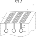
- FIG. 2 is a transparent perspective view of the block in FIG. 1 .
- hard rubber 7 with a higher elastic modulus than that of the tread rubber is disposed in a tire radial region including at least the opening to the tread surface 1 of the walls defining the widthwise sipe 6 (the entire region of the walls in the present example).
- the hard rubber 7 is disposed so as to extend continuously across both walls defining the widthwise sipe 6 and the sipe bottom.
- the elastic modulus of the tread rubber can, for example, be between 2 MPa and 4 MPa.
- the elastic modulus of the hard rubber 7 can be in a range higher than the elastic modulus of the tread rubber, such as 3 MPa to 6 MPa.
- the thickness of the hard rubber (the thickness measured in the normal direction to the groove wall, or the maximum thickness in a case in which the thickness varies) can be between 0.2 mm and 1 mm.
- the thickness of the hard rubber is preferably substantially constant over the entire region across which the hard rubber extends. While not particularly limited, the tread rubber is preferably foamed rubber, and the hard rubber is preferably non-foamed rubber.
- the hard rubber can be provided by, for example, providing a film of unvulcanized hard rubber in advance at the position, before vulcanization, at which the widthwise sipe is to be provided, so that the hard rubber is located on the walls of the widthwise sipe when a blade is used to form the widthwise sipe.
- FIG. 3 is a plan view of the block in FIG. 1 .
- Microfabrication 8 is applied in a region of the tread surface 1 surrounding at least a portion of the opening (the entire opening in the illustrated example) of the widthwise sipe 6 to the tread surface 1. For the sake of simplicity, the microfabrication 8 is not depicted in FIG. 1 .
- the drainage performance and the on-ice performance can be improved, since one or more widthwise sipes 6 are provided in the blocks 5.
- the block rigidity can be increased and the on-snow performance improved, since the hard rubber 7 with a higher elastic modulus than that of the tread rubber is disposed in a tire radial region including at least the opening to the tread surface 1 of the walls defining the walls of the widthwise sipe 6 (the entire region of the walls in the present example).
- the microfabrication 8 is therefore applied in a region of the tread surface 1 surrounding at least a portion of the opening (the entire opening in the illustrated example) of the widthwise sipe 6 to the tread surface 1. This can improve the grounding property at the corresponding location and can improve the on-ice and on-snow grip performance.
- both the on-ice performance and the on-snow performance can thus be improved.
- the hard rubber is preferably disposed over the entire area of the walls that define the widthwise sipe. This configuration can further increase the block rigidity and further improve the on-snow performance.
- the area surrounding at least a part of the opening of the width directional sipe to the tread surface preferably includes all of the opening, as in the illustrated example. This configuration can sufficiently secure the region for improving the grounding property and can further improve the on-ice and on-snow grip performance.
- the aforementioned region preferably includes the range from the opening of the widthwise sipe to the tread surface to a position 2 mm away on each side in the tire circumferential direction.
- This configuration can sufficiently secure, in the tire circumferential direction, the region for improving the grounding property and can further improve the on-ice and on-snow grip performance.
- two of the aforementioned regions that are adjacent in the tire circumferential direction are preferably 1 mm or more and 10 mm or less apart in the tire circumferential direction (indicated as distance B in FIG. 3 ).
- Two of the regions that are adjacent in the tire circumferential direction are more preferably 1 mm or more and 5 mm or less apart in the tire circumferential direction.
- the distance B being 1 mm or more, a decrease in block rigidity can be suppressed, whereas by the distance B being 10 mm (more preferably 5 mm) or less, the edge pressure can be sufficiently secured.
- the separation distance refers to the minimum separation distance.
- the ratio A/B preferably satisfies the following expression, where A (mm) is the length of the region in the tire circumferential direction, and B (mm) is the separation distance between the two regions in the tire circumferential direction. 0.1 ⁇ A / B ⁇ 6
- the ratio A/B being 0.1 or more, the improvement in grip by microfabrication can be effectively achieved, whereas by the ratio A/B being 6 or less, the occurrence of abnormal wear between adjacent sipes can be suppressed.
- the length A refers to the minimum length.
- the separation distance B refers to the minimum separation distance, as above.
- At least one end (both ends in the illustrated example) of the widthwise sipe preferably terminates within the block, and the region preferably extends from the end to a position 2 mm or more away in the tire width direction.
- This configuration can sufficiently secure, in the tire width direction, the region for improving the grounding property and can further improve the on-ice and on-snow grip performance.
- the microfabrication is preferably applied so that the surface roughness Ra of the aforementioned area is between 10 ⁇ m and 500 ⁇ m.
- the surface roughness Ra of the aforementioned region being 10 ⁇ m or more, the surface area of the aforementioned region is increased, whereas by the surface roughness Ra of the aforementioned area being 500 ⁇ m or less, the actual footprint area is increased relative to the surface area of the aforementioned region, thereby further improving the on-ice and on-snow grip performance.
- the surface roughness Ra of the aforementioned region is more preferably between 25 ⁇ m and 400 ⁇ m, even more preferably between 50 ⁇ m and 200 ⁇ m.
- the surface roughness Ra of the region of the widthwise sipe on one side in the tire circumferential direction is preferably larger than the surface roughness Ra of the region of the widthwise sipe on the other side in the tire circumferential direction. Improving the water drainage property is advantageous for the on-ice and on-snow grip performance on the stepping-in side, and improving the grounding property is advantageous for the on-ice and on-snow grip performance on the kicking-out side. Therefore, by the aforementioned one side in the tire circumferential direction being the stepping-in side, the on-ice and on-snow performance can be effectively improved.
- the surface roughness Ra of the region of the widthwise sipe on the stepping-in side of the block is preferably larger than the surface roughness Ra of the region of the widthwise sipe 6 on the kicking-out side of the block.
- the surface roughness Ra of the region of the widthwise sipe located farthest on one side in the tire circumferential direction (the stepping-in side) is preferably the largest.
- the surface roughness Ra of the region of the widthwise sipe 6 preferably decreases gradually from one side in the tire circumferential direction (the stepping-in side) to the other side in the tire circumferential direction (the kicking-out side).
- the surface roughness Ra of the aforementioned region need not be set to differ between widthwise sipes, however, and may be the same.
- the microfabrication is preferably applied so that the kurtosis Rku of the aforementioned region is between 2 and 6.
- the kurtosis Rku being 2 or more, the improvement in the grounding property can be efficiently achieved by microfabrication, whereas by the kurtosis Rku being set to 6 or less, abnormal wear and deterioration of the grip due to excessive surface roughness can be suppressed.
- the kurtosis Rku of the aforementioned region is more preferably between 3 and 5.
- the aforementioned region to which microfabrication is applied is rectangular in plan view, but this configuration is not limiting.
- the region can have various shapes, such as a partially rounded shape.
- the aforementioned region can have a parallelogram shape in plan view.
- the aforementioned microfabrication can be formed by any known technique, such as by projection of a blast material.
- the widthwise sipe in which the hard rubber is disposed and to which microfabrication is applied in the aforementioned region it suffices for the widthwise sipe in which the hard rubber is disposed and to which microfabrication is applied in the aforementioned region to be any one or more widthwise sipes among the plurality of widthwise sipes.
- the hard rubber is preferably disposed and microfabrication is preferably applied in the region at least at the widthwise sipe adjacent to an edge of the block on one side in the tire circumferential direction. Since the contribution to the edge effect is particularly large on the kicking-out side of the block, this configuration can in particular further improve the on-ice and on-snow grip performance effectively when the one side in the tire circumferential direction is set to the kicking-out side.
- the rotation direction of the pneumatic tire is preferably specified, and the hard rubber is preferably disposed and microfabrication is preferably applied in the region at least at the widthwise sipe located farthest on the kicking-out side of the block.
- each widthwise sipe 6 includes a constant sipe width portion 6a on the tread surface 1 side, in which the sipe width (width measured parallel to the tread surface 1 in a cross-sectional view) is constant (equivalent to the opening width at the tread surface 1), and a widened portion 6b on the sipe bottom side, in which the sipe width is larger than on the tread surface 1 side.
- the widened portion 6d is substantially circular in a cross-sectional view. In this way, the widthwise sipe includes a widened portion, at the groove bottom side, in which the sipe width is larger than at the tread surface side.
- block fragments (the portions of blocks divided by the widthwise sipes) can more easily collapse, improving the edge pressure and further improving the grip performance on ice and snow.
- This configuration can also improve the drainage performance when wear progresses.
- the portion farther outward in the tire radial direction than the widened portion 6b is the constant sipe width portion 6a that has a constant sipe width, but this portion can also be a portion with a variable sipe width.
- the sipe width of the constant sipe width portion 6a is not particularly limited but can, for example, be between 0.2 mm and 1.0 mm.
- the maximum width of the widened portion 6b is not particularly limited but can, for example, be between 1.2 mm and 6.0 mm.
- the extension length in the depth direction of the constant sipe width portion 6a is not particularly limited but can, for example, be between 2.0 mm and 12 mm.
- the extension length in the depth direction of the widened portion 6b is not particularly limited but can, for example, be between 2.5 mm and 11.0 mm.
- the block preferably includes a plurality of widthwise sipes, and the width of the widened portion on one side in the tire circumferential direction is preferably larger than the width of the widened portion on another side in the tire circumferential direction.
- the contribution to the edge effect is particularly large on the kicking-out side of the block. Therefore, when the one side in the tire circumferential direction is set to the kicking-out side, the block fragments (the portions of blocks divided by the widthwise sipes) on the kicking-out side can more easily collapse, and in particular the on-ice and on-snow grip performance can be further improved effectively.
- the width of the widened portion preferably decreases gradually from one side in the tire circumferential direction to the other side in the tire circumferential direction.
- the rotation direction of the pneumatic tire is preferably specified, and the width of the widened portion on the kicking-out side of the block is preferably larger than the width of the widened portion on the stepping-in side of the block.
- the width of the widened portion preferably decreases gradually from the kicking-out side of the block to the stepping-in side of the block.
- the pneumatic tire tread of the present invention can suitably be used in a studless tire.
Landscapes
- Engineering & Computer Science (AREA)
- Mechanical Engineering (AREA)
- Tires In General (AREA)
Claims (14)
- Luftreifen, der, auf einer Lauffläche (1), eine Vielzahl von umlaufenden Hauptrillen (2, 2a, 2b, 2c), die sich in einer Reifenumfangsrichtung erstrecken, und eine Vielzahl von Stegabschnitten (3, 3a, 3b, 3c, 3d), die zwischen umlaufenden Hauptrillen, die in einer Reifenbreitenrichtung unter der Vielzahl von umlaufenden Hauptrillen benachbart sind, oder durch die umlaufenden Hauptrillen und Laufflächenkanten (TE) definiert sind, umfasst, wobeidie Stegabschnitte eine Vielzahl von Breitenrichtungsrillen (4) umfassen, die sich in der Reifenbreitenrichtung erstrecken, und durch die Breitenrichtungsrillen in eine Vielzahl von Blöcken (5) geteilt sind,mindestens eine Breitenrichtungslamelle (6), die sich in der Reifenbreitenrichtung erstreckt, innerhalb der Blöcke eingeschlossen ist,harter Gummi (7) mit einem höheren Elastizitätsmodul als derjenige von Laufflächengummi in einem Reifenradialbereich angeordnet ist, der mindestens eine Öffnung zu der Lauffläche einer Wand, welche die Breitenrichtungslamelle definiert, einschließt, unddadurch gekennzeichnet, dass Mikrofabrikation (8) in mindestens einem Bereich der Lauffläche angewendet wird, der mindestens einen Abschnitt der Öffnung der Breitenrichtungslamelle zu der Lauffläche umgibt,wobei die Breitenrichtungslamelle einen verbreiterten Abschnitt (6b), an einer Rillensohlenseite, einschließt, in dem eine Lamellenbreite größer ist als an der Laufflächenseite.
- Luftreifen nach Anspruch 1, wobei der harte Gummi über ein gesamtes Gebiet der Wand, welche die Breitenrichtungslamelle definiert, angeordnet ist.
- Luftreifen nach Anspruch 1 oder 2, wobei der Bereich eine Spanne von der Öffnung der Breitenrichtungslamelle zu der Lauffläche bis zu einer Position, 2 mm entfernt auf jeder Seite in der Reifenumfangsrichtung, einschließt.
- Luftreifen nach einem der Ansprüche 1 bis 3, wobeidie mindestens eine Breitenrichtungslamelle, die innerhalb der Blöcke eingeschlossen ist, eine Vielzahl von Breitenrichtungslamellen umfasst undder mindestens eine Bereich zwei Bereiche umfasst, die in der Reifenumfangsrichtung benachbart sind und in der Reifenumfangsrichtung 1 mm oder mehr und 10 mm oder weniger voneinander beabstandet sind.
- Luftreifen nach einem der Ansprüche 1 bis 4, wobeidie mindestens eine Breitenrichtungslamelle, die innerhalb der Blöcke eingeschlossen ist, eine Vielzahl von Breitenrichtungslamellen umfasst,A (mm) eine Länge des Bereichs in der Reifenumfangsrichtung ist,der mindestens eine Bereich zwei Bereiche umfasst, die in der Reifenumfangsrichtung benachbart sind, und B (mm) ein Trennungsabstand zwischen den zwei Bereichen in der Reifenumfangsrichtung ist, und

- Luftreifen nach einem der Ansprüche 1 bis 5, wobeimindestens ein Ende der Breitenrichtungslamelle innerhalb des Blocks endet; undder Bereich eine Spanne von dem mindestens einen Ende der Breitenrichtungslamelle bis zu einer Position, 2 mm entfernt in der Reifenumfangsrichtung, einschließt.
- Luftreifen nach einem der Ansprüche 1 bis 6, wobei die Mikrofabrikation angewendet wird, sodass eine Oberflächenrauheit Ra des Bereichs zwischen 10 µm und 500 µm beträgt.
- Luftreifen nach Anspruch 7, wobeidie mindestens eine Breitenrichtungslamelle, die innerhalb der Blöcke eingeschlossen ist, eine Vielzahl von Breitenrichtungslamellen umfasst, undeine Oberflächenrauheit Ra des Bereichs der Breitenrichtungslamelle auf einer Seite in der Reifenumfangsrichtung größer ist als eine Oberflächenrauheit Ra des Bereichs der Breitenrichtungslamelle auf einer anderen Seite in der Reifenumfangsrichtung.
- Luftreifen nach Anspruch 7 oder 8, wobeieine Rotationsrichtung des Luftreifens spezifiziert ist,die mindestens eine Breitenrichtungslamelle, die innerhalb der Blöcke eingeschlossen ist, eine Vielzahl von Breitenrichtungslamellen umfasst, undeine Oberflächenrauheit Ra des Bereichs der Breitenrichtungslamelle auf einer Seite der ersten Berührung des Blocks größer ist als eine Oberflächenrauheit Ra des Bereichs der Breitenrichtungslamelle auf einer Seite der letzten Ablösung des Blocks.
- Luftreifen nach einem der Ansprüche 1 bis 9, wobei die Mikrofabrikation angewendet wird, sodass eine Schärfe der Oberflächenrauheit, die Kurtosis Rku, berechnet auf Grundlage von ISO 25178, des Bereichs zwischen 2 und 6 beträgt.
- Luftreifen nach einem der Ansprüche 1 bis 10, wobeidie mindestens eine Breitenrichtungslamelle eine Vielzahl von Breitenrichtungslamellen umfasst undmindestens an der Breitenrichtungslamelle, die zu einer Kante des Blocks auf einer Seite in der Reifenumfangsrichtung benachbart ist, der harte Gummi angeordnet ist und Mikrofabrikation in dem Bereich angewendet wird.
- Luftreifen nach einem der Ansprüche 1 bis 11, wobeieine Rotationsrichtung des Luftreifens spezifiziert ist,die mindestens eine Breitenrichtungslamelle, die innerhalb der Blöcke eingeschlossen ist, eine Vielzahl von Breitenrichtungslamellen umfasst, undmindestens an der Breitenrichtungslamelle, die sich am weitesten auf einer Seite der letzten Ablösung des Blocks befindet, der harte Gummi angeordnet ist und Mikrofabrikation in dem Bereich angewendet wird.
- Luftreifen nach einem der Ansprüche 1 bis 12, wobeidie mindestens eine Breitenrichtungslamelle, die innerhalb der Blöcke eingeschlossen ist, eine Vielzahl von Breitenrichtungslamellen umfasst, undeine Breite des verbreiterten Abschnitts auf einer Seite in der Reifenumfangsrichtung größer ist als eine Breite des verbreiterten Abschnitts auf einer anderen Seite in der Reifenumfangsrichtung.
- Luftreifen nach Anspruch 13, wobeieine Rotationsrichtung des Luftreifens spezifiziert ist,die mindestens eine Breitenrichtungslamelle, die innerhalb der Blöcke eingeschlossen ist, eine Vielzahl von Breitenrichtungslamellen umfasst, undeine Breite des verbreiterten Abschnitts auf einer Seite der letzten Ablösung des Blocks größer ist als eine Breite des verbreiterten Abschnitts auf einer Seite der ersten Berührung des Blocks.
Applications Claiming Priority (2)
| Application Number | Priority Date | Filing Date | Title |
|---|---|---|---|
| JP2019220446A JP7284693B2 (ja) | 2019-12-05 | 2019-12-05 | 空気入りタイヤ |
| PCT/JP2020/024393 WO2021111662A1 (ja) | 2019-12-05 | 2020-06-22 | 空気入りタイヤ |
Publications (3)
| Publication Number | Publication Date |
|---|---|
| EP4043244A1 EP4043244A1 (de) | 2022-08-17 |
| EP4043244A4 EP4043244A4 (de) | 2022-11-09 |
| EP4043244B1 true EP4043244B1 (de) | 2024-06-12 |
Family
ID=76219224
Family Applications (1)
| Application Number | Title | Priority Date | Filing Date |
|---|---|---|---|
| EP20897396.6A Active EP4043244B1 (de) | 2019-12-05 | 2020-06-22 | Luftreifen |
Country Status (5)
| Country | Link |
|---|---|
| US (1) | US20230001743A1 (de) |
| EP (1) | EP4043244B1 (de) |
| JP (1) | JP7284693B2 (de) |
| CN (1) | CN114746285B (de) |
| WO (1) | WO2021111662A1 (de) |
Families Citing this family (3)
| Publication number | Priority date | Publication date | Assignee | Title |
|---|---|---|---|---|
| JP7103306B2 (ja) * | 2019-06-04 | 2022-07-20 | 横浜ゴム株式会社 | タイヤ成形用金型 |
| JP7620537B2 (ja) * | 2021-11-25 | 2025-01-23 | 株式会社ブリヂストン | 乗用車用空気入りラジアルタイヤ |
| JP2026037607A (ja) * | 2024-08-22 | 2026-03-06 | 横浜ゴム株式会社 | タイヤ |
Family Cites Families (30)
| Publication number | Priority date | Publication date | Assignee | Title |
|---|---|---|---|---|
| JP2779765B2 (ja) * | 1994-03-18 | 1998-07-23 | 有限会社新津 | 空気入りタイヤとそれを製造する加硫成型用金型 |
| JPH10138709A (ja) * | 1996-11-13 | 1998-05-26 | Yokohama Rubber Co Ltd:The | 重荷重用空気入りタイヤ |
| JPH1178428A (ja) * | 1997-09-09 | 1999-03-23 | Yokohama Rubber Co Ltd:The | 空気入りタイヤ |
| JPH11291717A (ja) * | 1998-04-13 | 1999-10-26 | Bridgestone Corp | 空気入りタイヤ |
| JP2006082632A (ja) * | 2004-09-15 | 2006-03-30 | Bridgestone Corp | 空気入りタイヤ |
| JP2006327298A (ja) * | 2005-05-24 | 2006-12-07 | Bridgestone Corp | 空気入りタイヤ |
| JP5060973B2 (ja) * | 2008-01-18 | 2012-10-31 | 株式会社ブリヂストン | 空気入りタイヤ |
| FR2928866B1 (fr) * | 2008-03-20 | 2010-03-19 | Michelin Soc Tech | Sculpture pour bande de roulement de pneu |
| WO2010047353A1 (ja) * | 2008-10-21 | 2010-04-29 | 株式会社ブリヂストン | タイヤ |
| JP5115487B2 (ja) * | 2009-01-27 | 2013-01-09 | 横浜ゴム株式会社 | 空気入りタイヤ |
| JP5399849B2 (ja) * | 2009-10-08 | 2014-01-29 | 株式会社ブリヂストン | 空気入りタイヤ |
| JP5437851B2 (ja) * | 2010-02-19 | 2014-03-12 | 株式会社ブリヂストン | 空気入りタイヤ |
| JP5356285B2 (ja) * | 2010-03-09 | 2013-12-04 | 東洋ゴム工業株式会社 | 空気入りタイヤ |
| FR2962372B1 (fr) * | 2010-07-06 | 2014-05-02 | Michelin Soc Tech | Dispositif de protection de bande de roulement |
| JP5894412B2 (ja) * | 2011-10-27 | 2016-03-30 | 住友ゴム工業株式会社 | 空気入りタイヤ |
| JP6069709B2 (ja) * | 2011-12-16 | 2017-02-01 | コンパニー ゼネラール デ エタブリッスマン ミシュラン | 空気入りタイヤ用トレッド |
| JP6348248B2 (ja) * | 2011-12-28 | 2018-06-27 | 株式会社ブリヂストン | タイヤおよびタイヤ成形用金型 |
| JP6019780B2 (ja) * | 2012-06-08 | 2016-11-02 | 横浜ゴム株式会社 | 空気入りタイヤ |
| JP2014097697A (ja) * | 2012-11-13 | 2014-05-29 | Yokohama Rubber Co Ltd:The | 空気入りタイヤ |
| JP6134583B2 (ja) * | 2013-05-28 | 2017-05-24 | 株式会社ブリヂストン | タイヤ |
| FR3014750B1 (fr) | 2013-12-17 | 2017-02-24 | Michelin & Cie | Bande de roulement comprenant des pavés et de fines rainures sur les pavés |
| JP6605460B2 (ja) * | 2014-05-30 | 2019-11-13 | 株式会社ブリヂストン | 乗用車用空気入りラジアルタイヤ |
| FR3044598A1 (fr) * | 2015-12-04 | 2017-06-09 | Michelin & Cie | Pneumatique avec une bande de roulement comportant un renforcement circonferentiel |
| JP7009787B2 (ja) * | 2017-06-08 | 2022-01-26 | 横浜ゴム株式会社 | 空気入りタイヤ |
| JP7092467B2 (ja) * | 2017-06-16 | 2022-06-28 | 株式会社ブリヂストン | タイヤ |
| US20200369091A1 (en) * | 2017-07-31 | 2020-11-26 | Compagnie Generale Des Etablissments Michelin | Tire tread having tread blocks with inclined trailing side and sipe |
| JP2019043517A (ja) * | 2017-09-07 | 2019-03-22 | 横浜ゴム株式会社 | 空気入りタイヤ |
| JP6949649B2 (ja) * | 2017-10-02 | 2021-10-13 | 株式会社ブリヂストン | タイヤ |
| JP7037350B2 (ja) * | 2017-12-22 | 2022-03-16 | Toyo Tire株式会社 | 空気入りタイヤ |
| JP6915649B2 (ja) * | 2019-07-03 | 2021-08-04 | 横浜ゴム株式会社 | タイヤ加硫用モールドおよびタイヤの製造方法 |
-
2019
- 2019-12-05 JP JP2019220446A patent/JP7284693B2/ja active Active
-
2020
- 2020-06-22 WO PCT/JP2020/024393 patent/WO2021111662A1/ja not_active Ceased
- 2020-06-22 CN CN202080083279.8A patent/CN114746285B/zh active Active
- 2020-06-22 EP EP20897396.6A patent/EP4043244B1/de active Active
- 2020-06-22 US US17/756,256 patent/US20230001743A1/en not_active Abandoned
Also Published As
| Publication number | Publication date |
|---|---|
| EP4043244A4 (de) | 2022-11-09 |
| CN114746285A (zh) | 2022-07-12 |
| JP7284693B2 (ja) | 2023-05-31 |
| US20230001743A1 (en) | 2023-01-05 |
| JP2021088308A (ja) | 2021-06-10 |
| WO2021111662A1 (ja) | 2021-06-10 |
| EP4043244A1 (de) | 2022-08-17 |
| CN114746285B (zh) | 2023-07-25 |
Similar Documents
| Publication | Publication Date | Title |
|---|---|---|
| US10836215B2 (en) | Tire | |
| EP3213930B1 (de) | Luftreifen | |
| EP2578418B1 (de) | Luftreifen | |
| EP2239153B1 (de) | Luftreifen | |
| EP3098089B1 (de) | Winterreifen | |
| EP2586627B1 (de) | Luftreifen | |
| EP4043244B1 (de) | Luftreifen | |
| EP3228477A1 (de) | Luftreifen | |
| CN111070974A (zh) | 充气轮胎 | |
| EP4424524B1 (de) | Reifen | |
| JP7106950B2 (ja) | タイヤ | |
| JP6946658B2 (ja) | 空気入りタイヤ | |
| EP4400335A1 (de) | Luftreifen | |
| US12533912B2 (en) | Tire | |
| CN111511586B (zh) | 可镶钉轮胎及充气轮胎 | |
| EP3501849B1 (de) | Luftreifen | |
| EP3020573B1 (de) | Luftreifen | |
| CN113442660B (zh) | 充气轮胎 | |
| EP4046825B1 (de) | Luftreifen | |
| EP4046826B1 (de) | Luftreifen | |
| CN115803208A (zh) | 轮胎 | |
| CN112976954A (zh) | 轮胎 | |
| EP4438338A1 (de) | Reifen mit verbessertem laufflächenprofil |
Legal Events
| Date | Code | Title | Description |
|---|---|---|---|
| STAA | Information on the status of an ep patent application or granted ep patent |
Free format text: STATUS: THE INTERNATIONAL PUBLICATION HAS BEEN MADE |
|
| PUAI | Public reference made under article 153(3) epc to a published international application that has entered the european phase |
Free format text: ORIGINAL CODE: 0009012 |
|
| STAA | Information on the status of an ep patent application or granted ep patent |
Free format text: STATUS: REQUEST FOR EXAMINATION WAS MADE |
|
| 17P | Request for examination filed |
Effective date: 20220510 |
|
| AK | Designated contracting states |
Kind code of ref document: A1 Designated state(s): AL AT BE BG CH CY CZ DE DK EE ES FI FR GB GR HR HU IE IS IT LI LT LU LV MC MK MT NL NO PL PT RO RS SE SI SK SM TR |
|
| A4 | Supplementary search report drawn up and despatched |
Effective date: 20221012 |
|
| RIC1 | Information provided on ipc code assigned before grant |
Ipc: B60C 11/03 20060101ALI20221006BHEP Ipc: B60C 11/11 20060101ALI20221006BHEP Ipc: B60C 11/12 20060101ALI20221006BHEP Ipc: B60C 11/00 20060101AFI20221006BHEP |
|
| DAV | Request for validation of the european patent (deleted) | ||
| DAX | Request for extension of the european patent (deleted) | ||
| GRAP | Despatch of communication of intention to grant a patent |
Free format text: ORIGINAL CODE: EPIDOSNIGR1 |
|
| STAA | Information on the status of an ep patent application or granted ep patent |
Free format text: STATUS: GRANT OF PATENT IS INTENDED |
|
| INTG | Intention to grant announced |
Effective date: 20240112 |
|
| P01 | Opt-out of the competence of the unified patent court (upc) registered |
Effective date: 20240126 |
|
| GRAS | Grant fee paid |
Free format text: ORIGINAL CODE: EPIDOSNIGR3 |
|
| GRAA | (expected) grant |
Free format text: ORIGINAL CODE: 0009210 |
|
| STAA | Information on the status of an ep patent application or granted ep patent |
Free format text: STATUS: THE PATENT HAS BEEN GRANTED |
|
| AK | Designated contracting states |
Kind code of ref document: B1 Designated state(s): AL AT BE BG CH CY CZ DE DK EE ES FI FR GB GR HR HU IE IS IT LI LT LU LV MC MK MT NL NO PL PT RO RS SE SI SK SM TR |
|
| REG | Reference to a national code |
Ref country code: GB Ref legal event code: FG4D |
|
| REG | Reference to a national code |
Ref country code: CH Ref legal event code: EP |
|
| REG | Reference to a national code |
Ref country code: IE Ref legal event code: FG4D |
|
| REG | Reference to a national code |
Ref country code: DE Ref legal event code: R096 Ref document number: 602020032482 Country of ref document: DE |
|
| PG25 | Lapsed in a contracting state [announced via postgrant information from national office to epo] |
Ref country code: BG Free format text: LAPSE BECAUSE OF FAILURE TO SUBMIT A TRANSLATION OF THE DESCRIPTION OR TO PAY THE FEE WITHIN THE PRESCRIBED TIME-LIMIT Effective date: 20240612 |
|
| PG25 | Lapsed in a contracting state [announced via postgrant information from national office to epo] |
Ref country code: HR Free format text: LAPSE BECAUSE OF FAILURE TO SUBMIT A TRANSLATION OF THE DESCRIPTION OR TO PAY THE FEE WITHIN THE PRESCRIBED TIME-LIMIT Effective date: 20240612 Ref country code: FI Free format text: LAPSE BECAUSE OF FAILURE TO SUBMIT A TRANSLATION OF THE DESCRIPTION OR TO PAY THE FEE WITHIN THE PRESCRIBED TIME-LIMIT Effective date: 20240612 |
|
| REG | Reference to a national code |
Ref country code: LT Ref legal event code: MG9D |
|
| PG25 | Lapsed in a contracting state [announced via postgrant information from national office to epo] |
Ref country code: GR Free format text: LAPSE BECAUSE OF FAILURE TO SUBMIT A TRANSLATION OF THE DESCRIPTION OR TO PAY THE FEE WITHIN THE PRESCRIBED TIME-LIMIT Effective date: 20240913 |
|
| REG | Reference to a national code |
Ref country code: NL Ref legal event code: MP Effective date: 20240612 |
|
| PG25 | Lapsed in a contracting state [announced via postgrant information from national office to epo] |
Ref country code: ES Free format text: LAPSE BECAUSE OF FAILURE TO SUBMIT A TRANSLATION OF THE DESCRIPTION OR TO PAY THE FEE WITHIN THE PRESCRIBED TIME-LIMIT Effective date: 20240612 |
|
| PG25 | Lapsed in a contracting state [announced via postgrant information from national office to epo] |
Ref country code: LV Free format text: LAPSE BECAUSE OF FAILURE TO SUBMIT A TRANSLATION OF THE DESCRIPTION OR TO PAY THE FEE WITHIN THE PRESCRIBED TIME-LIMIT Effective date: 20240612 |
|
| PG25 | Lapsed in a contracting state [announced via postgrant information from national office to epo] |
Ref country code: NO Free format text: LAPSE BECAUSE OF FAILURE TO SUBMIT A TRANSLATION OF THE DESCRIPTION OR TO PAY THE FEE WITHIN THE PRESCRIBED TIME-LIMIT Effective date: 20240912 Ref country code: LV Free format text: LAPSE BECAUSE OF FAILURE TO SUBMIT A TRANSLATION OF THE DESCRIPTION OR TO PAY THE FEE WITHIN THE PRESCRIBED TIME-LIMIT Effective date: 20240612 Ref country code: HR Free format text: LAPSE BECAUSE OF FAILURE TO SUBMIT A TRANSLATION OF THE DESCRIPTION OR TO PAY THE FEE WITHIN THE PRESCRIBED TIME-LIMIT Effective date: 20240612 Ref country code: GR Free format text: LAPSE BECAUSE OF FAILURE TO SUBMIT A TRANSLATION OF THE DESCRIPTION OR TO PAY THE FEE WITHIN THE PRESCRIBED TIME-LIMIT Effective date: 20240913 Ref country code: FI Free format text: LAPSE BECAUSE OF FAILURE TO SUBMIT A TRANSLATION OF THE DESCRIPTION OR TO PAY THE FEE WITHIN THE PRESCRIBED TIME-LIMIT Effective date: 20240612 Ref country code: ES Free format text: LAPSE BECAUSE OF FAILURE TO SUBMIT A TRANSLATION OF THE DESCRIPTION OR TO PAY THE FEE WITHIN THE PRESCRIBED TIME-LIMIT Effective date: 20240612 Ref country code: BG Free format text: LAPSE BECAUSE OF FAILURE TO SUBMIT A TRANSLATION OF THE DESCRIPTION OR TO PAY THE FEE WITHIN THE PRESCRIBED TIME-LIMIT Effective date: 20240612 Ref country code: RS Free format text: LAPSE BECAUSE OF FAILURE TO SUBMIT A TRANSLATION OF THE DESCRIPTION OR TO PAY THE FEE WITHIN THE PRESCRIBED TIME-LIMIT Effective date: 20240912 |
|
| PG25 | Lapsed in a contracting state [announced via postgrant information from national office to epo] |
Ref country code: NL Free format text: LAPSE BECAUSE OF FAILURE TO SUBMIT A TRANSLATION OF THE DESCRIPTION OR TO PAY THE FEE WITHIN THE PRESCRIBED TIME-LIMIT Effective date: 20240612 |
|
| REG | Reference to a national code |
Ref country code: AT Ref legal event code: MK05 Ref document number: 1693925 Country of ref document: AT Kind code of ref document: T Effective date: 20240612 |
|
| PG25 | Lapsed in a contracting state [announced via postgrant information from national office to epo] |
Ref country code: NL Free format text: LAPSE BECAUSE OF FAILURE TO SUBMIT A TRANSLATION OF THE DESCRIPTION OR TO PAY THE FEE WITHIN THE PRESCRIBED TIME-LIMIT Effective date: 20240612 |
|
| PG25 | Lapsed in a contracting state [announced via postgrant information from national office to epo] |
Ref country code: PT Free format text: LAPSE BECAUSE OF FAILURE TO SUBMIT A TRANSLATION OF THE DESCRIPTION OR TO PAY THE FEE WITHIN THE PRESCRIBED TIME-LIMIT Effective date: 20241014 |
|
| PG25 | Lapsed in a contracting state [announced via postgrant information from national office to epo] |
Ref country code: PT Free format text: LAPSE BECAUSE OF FAILURE TO SUBMIT A TRANSLATION OF THE DESCRIPTION OR TO PAY THE FEE WITHIN THE PRESCRIBED TIME-LIMIT Effective date: 20241014 |
|
| PG25 | Lapsed in a contracting state [announced via postgrant information from national office to epo] |
Ref country code: PL Free format text: LAPSE BECAUSE OF FAILURE TO SUBMIT A TRANSLATION OF THE DESCRIPTION OR TO PAY THE FEE WITHIN THE PRESCRIBED TIME-LIMIT Effective date: 20240612 |
|
| PG25 | Lapsed in a contracting state [announced via postgrant information from national office to epo] |
Ref country code: EE Free format text: LAPSE BECAUSE OF FAILURE TO SUBMIT A TRANSLATION OF THE DESCRIPTION OR TO PAY THE FEE WITHIN THE PRESCRIBED TIME-LIMIT Effective date: 20240612 |
|
| PG25 | Lapsed in a contracting state [announced via postgrant information from national office to epo] |
Ref country code: AT Free format text: LAPSE BECAUSE OF FAILURE TO SUBMIT A TRANSLATION OF THE DESCRIPTION OR TO PAY THE FEE WITHIN THE PRESCRIBED TIME-LIMIT Effective date: 20240612 Ref country code: IS Free format text: LAPSE BECAUSE OF FAILURE TO SUBMIT A TRANSLATION OF THE DESCRIPTION OR TO PAY THE FEE WITHIN THE PRESCRIBED TIME-LIMIT Effective date: 20241012 |
|
| PG25 | Lapsed in a contracting state [announced via postgrant information from national office to epo] |
Ref country code: CZ Free format text: LAPSE BECAUSE OF FAILURE TO SUBMIT A TRANSLATION OF THE DESCRIPTION OR TO PAY THE FEE WITHIN THE PRESCRIBED TIME-LIMIT Effective date: 20240612 |
|
| PG25 | Lapsed in a contracting state [announced via postgrant information from national office to epo] |
Ref country code: SK Free format text: LAPSE BECAUSE OF FAILURE TO SUBMIT A TRANSLATION OF THE DESCRIPTION OR TO PAY THE FEE WITHIN THE PRESCRIBED TIME-LIMIT Effective date: 20240612 Ref country code: RO Free format text: LAPSE BECAUSE OF FAILURE TO SUBMIT A TRANSLATION OF THE DESCRIPTION OR TO PAY THE FEE WITHIN THE PRESCRIBED TIME-LIMIT Effective date: 20240612 |
|
| PG25 | Lapsed in a contracting state [announced via postgrant information from national office to epo] |
Ref country code: SM Free format text: LAPSE BECAUSE OF FAILURE TO SUBMIT A TRANSLATION OF THE DESCRIPTION OR TO PAY THE FEE WITHIN THE PRESCRIBED TIME-LIMIT Effective date: 20240612 |
|
| PG25 | Lapsed in a contracting state [announced via postgrant information from national office to epo] |
Ref country code: SM Free format text: LAPSE BECAUSE OF FAILURE TO SUBMIT A TRANSLATION OF THE DESCRIPTION OR TO PAY THE FEE WITHIN THE PRESCRIBED TIME-LIMIT Effective date: 20240612 Ref country code: SK Free format text: LAPSE BECAUSE OF FAILURE TO SUBMIT A TRANSLATION OF THE DESCRIPTION OR TO PAY THE FEE WITHIN THE PRESCRIBED TIME-LIMIT Effective date: 20240612 Ref country code: RO Free format text: LAPSE BECAUSE OF FAILURE TO SUBMIT A TRANSLATION OF THE DESCRIPTION OR TO PAY THE FEE WITHIN THE PRESCRIBED TIME-LIMIT Effective date: 20240612 Ref country code: PL Free format text: LAPSE BECAUSE OF FAILURE TO SUBMIT A TRANSLATION OF THE DESCRIPTION OR TO PAY THE FEE WITHIN THE PRESCRIBED TIME-LIMIT Effective date: 20240612 Ref country code: IS Free format text: LAPSE BECAUSE OF FAILURE TO SUBMIT A TRANSLATION OF THE DESCRIPTION OR TO PAY THE FEE WITHIN THE PRESCRIBED TIME-LIMIT Effective date: 20241012 Ref country code: EE Free format text: LAPSE BECAUSE OF FAILURE TO SUBMIT A TRANSLATION OF THE DESCRIPTION OR TO PAY THE FEE WITHIN THE PRESCRIBED TIME-LIMIT Effective date: 20240612 Ref country code: CZ Free format text: LAPSE BECAUSE OF FAILURE TO SUBMIT A TRANSLATION OF THE DESCRIPTION OR TO PAY THE FEE WITHIN THE PRESCRIBED TIME-LIMIT Effective date: 20240612 Ref country code: AT Free format text: LAPSE BECAUSE OF FAILURE TO SUBMIT A TRANSLATION OF THE DESCRIPTION OR TO PAY THE FEE WITHIN THE PRESCRIBED TIME-LIMIT Effective date: 20240612 |
|
| REG | Reference to a national code |
Ref country code: CH Ref legal event code: PL |
|
| PG25 | Lapsed in a contracting state [announced via postgrant information from national office to epo] |
Ref country code: IT Free format text: LAPSE BECAUSE OF FAILURE TO SUBMIT A TRANSLATION OF THE DESCRIPTION OR TO PAY THE FEE WITHIN THE PRESCRIBED TIME-LIMIT Effective date: 20240612 |
|
| PG25 | Lapsed in a contracting state [announced via postgrant information from national office to epo] |
Ref country code: LU Free format text: LAPSE BECAUSE OF NON-PAYMENT OF DUE FEES Effective date: 20240622 |
|
| REG | Reference to a national code |
Ref country code: DE Ref legal event code: R097 Ref document number: 602020032482 Country of ref document: DE |
|
| PG25 | Lapsed in a contracting state [announced via postgrant information from national office to epo] |
Ref country code: MC Free format text: LAPSE BECAUSE OF FAILURE TO SUBMIT A TRANSLATION OF THE DESCRIPTION OR TO PAY THE FEE WITHIN THE PRESCRIBED TIME-LIMIT Effective date: 20240612 |
|
| PG25 | Lapsed in a contracting state [announced via postgrant information from national office to epo] |
Ref country code: MC Free format text: LAPSE BECAUSE OF FAILURE TO SUBMIT A TRANSLATION OF THE DESCRIPTION OR TO PAY THE FEE WITHIN THE PRESCRIBED TIME-LIMIT Effective date: 20240612 |
|
| PG25 | Lapsed in a contracting state [announced via postgrant information from national office to epo] |
Ref country code: DK Free format text: LAPSE BECAUSE OF FAILURE TO SUBMIT A TRANSLATION OF THE DESCRIPTION OR TO PAY THE FEE WITHIN THE PRESCRIBED TIME-LIMIT Effective date: 20240612 |
|
| PLBE | No opposition filed within time limit |
Free format text: ORIGINAL CODE: 0009261 |
|
| STAA | Information on the status of an ep patent application or granted ep patent |
Free format text: STATUS: NO OPPOSITION FILED WITHIN TIME LIMIT |
|
| PG25 | Lapsed in a contracting state [announced via postgrant information from national office to epo] |
Ref country code: IE Free format text: LAPSE BECAUSE OF NON-PAYMENT OF DUE FEES Effective date: 20240622 |
|
| PG25 | Lapsed in a contracting state [announced via postgrant information from national office to epo] |
Ref country code: BE Free format text: LAPSE BECAUSE OF NON-PAYMENT OF DUE FEES Effective date: 20240630 Ref country code: CH Free format text: LAPSE BECAUSE OF NON-PAYMENT OF DUE FEES Effective date: 20240630 |
|
| REG | Reference to a national code |
Ref country code: BE Ref legal event code: MM Effective date: 20240630 |
|
| 26N | No opposition filed |
Effective date: 20250313 |
|
| GBPC | Gb: european patent ceased through non-payment of renewal fee |
Effective date: 20240912 |
|
| PGFP | Annual fee paid to national office [announced via postgrant information from national office to epo] |
Ref country code: DE Payment date: 20250618 Year of fee payment: 6 |
|
| PG25 | Lapsed in a contracting state [announced via postgrant information from national office to epo] |
Ref country code: GB Free format text: LAPSE BECAUSE OF NON-PAYMENT OF DUE FEES Effective date: 20240912 |
|
| PGFP | Annual fee paid to national office [announced via postgrant information from national office to epo] |
Ref country code: FR Payment date: 20250627 Year of fee payment: 6 |
|
| PG25 | Lapsed in a contracting state [announced via postgrant information from national office to epo] |
Ref country code: SE Free format text: LAPSE BECAUSE OF FAILURE TO SUBMIT A TRANSLATION OF THE DESCRIPTION OR TO PAY THE FEE WITHIN THE PRESCRIBED TIME-LIMIT Effective date: 20240612 |
|
| PG25 | Lapsed in a contracting state [announced via postgrant information from national office to epo] |
Ref country code: CY Free format text: LAPSE BECAUSE OF FAILURE TO SUBMIT A TRANSLATION OF THE DESCRIPTION OR TO PAY THE FEE WITHIN THE PRESCRIBED TIME-LIMIT; INVALID AB INITIO Effective date: 20200622 |
|
| PG25 | Lapsed in a contracting state [announced via postgrant information from national office to epo] |
Ref country code: HU Free format text: LAPSE BECAUSE OF FAILURE TO SUBMIT A TRANSLATION OF THE DESCRIPTION OR TO PAY THE FEE WITHIN THE PRESCRIBED TIME-LIMIT; INVALID AB INITIO Effective date: 20200622 |