EP4036626B1 - Weitwinkelobjektiv - Google Patents
Weitwinkelobjektiv Download PDFInfo
- Publication number
- EP4036626B1 EP4036626B1 EP22152955.5A EP22152955A EP4036626B1 EP 4036626 B1 EP4036626 B1 EP 4036626B1 EP 22152955 A EP22152955 A EP 22152955A EP 4036626 B1 EP4036626 B1 EP 4036626B1
- Authority
- EP
- European Patent Office
- Prior art keywords
- optical system
- vehicle
- lens
- view
- angle
- Prior art date
- Legal status (The legal status is an assumption and is not a legal conclusion. Google has not performed a legal analysis and makes no representation as to the accuracy of the status listed.)
- Active
Links
Images


Classifications
-
- G—PHYSICS
- G02—OPTICS
- G02B—OPTICAL ELEMENTS, SYSTEMS OR APPARATUS
- G02B13/00—Optical objectives specially designed for the purposes specified below
-
- G—PHYSICS
- G02—OPTICS
- G02B—OPTICAL ELEMENTS, SYSTEMS OR APPARATUS
- G02B9/00—Optical objectives characterised both by the number of the components and their arrangements according to their sign, i.e. + or -
- G02B9/64—Optical objectives characterised both by the number of the components and their arrangements according to their sign, i.e. + or - having more than six components
-
- B—PERFORMING OPERATIONS; TRANSPORTING
- B60—VEHICLES IN GENERAL
- B60R—VEHICLES, VEHICLE FITTINGS, OR VEHICLE PARTS, NOT OTHERWISE PROVIDED FOR
- B60R1/00—Optical viewing arrangements; Real-time viewing arrangements for drivers or passengers using optical image capturing systems, e.g. cameras or video systems specially adapted for use in or on vehicles
-
- B—PERFORMING OPERATIONS; TRANSPORTING
- B60—VEHICLES IN GENERAL
- B60W—CONJOINT CONTROL OF VEHICLE SUB-UNITS OF DIFFERENT TYPE OR DIFFERENT FUNCTION; CONTROL SYSTEMS SPECIALLY ADAPTED FOR HYBRID VEHICLES; ROAD VEHICLE DRIVE CONTROL SYSTEMS FOR PURPOSES NOT RELATED TO THE CONTROL OF A PARTICULAR SUB-UNIT
- B60W30/00—Purposes of road vehicle drive control systems not related to the control of a particular sub-unit, e.g. of systems using conjoint control of vehicle sub-units
- B60W30/08—Active safety systems predicting or avoiding probable or impending collision or attempting to minimise its consequences
- B60W30/095—Predicting travel path or likelihood of collision
- B60W30/0956—Predicting travel path or likelihood of collision the prediction being responsive to traffic or environmental parameters
-
- G—PHYSICS
- G02—OPTICS
- G02B—OPTICAL ELEMENTS, SYSTEMS OR APPARATUS
- G02B13/00—Optical objectives specially designed for the purposes specified below
- G02B13/001—Miniaturised objectives for electronic devices, e.g. portable telephones, webcams, PDAs, small digital cameras
- G02B13/0015—Miniaturised objectives for electronic devices, e.g. portable telephones, webcams, PDAs, small digital cameras characterised by the lens design
- G02B13/002—Miniaturised objectives for electronic devices, e.g. portable telephones, webcams, PDAs, small digital cameras characterised by the lens design having at least one aspherical surface
- G02B13/0045—Miniaturised objectives for electronic devices, e.g. portable telephones, webcams, PDAs, small digital cameras characterised by the lens design having at least one aspherical surface having five or more lenses
-
- G—PHYSICS
- G02—OPTICS
- G02B—OPTICAL ELEMENTS, SYSTEMS OR APPARATUS
- G02B13/00—Optical objectives specially designed for the purposes specified below
- G02B13/06—Panoramic objectives; So-called "sky lenses" including panoramic objectives having reflecting surfaces
-
- G—PHYSICS
- G02—OPTICS
- G02B—OPTICAL ELEMENTS, SYSTEMS OR APPARATUS
- G02B13/00—Optical objectives specially designed for the purposes specified below
- G02B13/18—Optical objectives specially designed for the purposes specified below with lenses having one or more non-spherical faces, e.g. for reducing geometrical aberration
-
- G—PHYSICS
- G03—PHOTOGRAPHY; CINEMATOGRAPHY; ANALOGOUS TECHNIQUES USING WAVES OTHER THAN OPTICAL WAVES; ELECTROGRAPHY; HOLOGRAPHY
- G03B—APPARATUS OR ARRANGEMENTS FOR TAKING PHOTOGRAPHS OR FOR PROJECTING OR VIEWING THEM; APPARATUS OR ARRANGEMENTS EMPLOYING ANALOGOUS TECHNIQUES USING WAVES OTHER THAN OPTICAL WAVES; ACCESSORIES THEREFOR
- G03B30/00—Camera modules comprising integrated lens units and imaging units, specially adapted for being embedded in other devices, e.g. mobile phones or vehicles
-
- G—PHYSICS
- G06—COMPUTING OR CALCULATING; COUNTING
- G06T—IMAGE DATA PROCESSING OR GENERATION, IN GENERAL
- G06T7/00—Image analysis
- G06T7/50—Depth or shape recovery
-
- G—PHYSICS
- G08—SIGNALLING
- G08B—SIGNALLING SYSTEMS, e.g. PERSONAL CALLING SYSTEMS; ORDER TELEGRAPHS; ALARM SYSTEMS
- G08B21/00—Alarms responsive to a single specified undesired or abnormal condition and not otherwise provided for
- G08B21/18—Status alarms
- G08B21/24—Reminder alarms, e.g. anti-loss alarms
-
- B—PERFORMING OPERATIONS; TRANSPORTING
- B60—VEHICLES IN GENERAL
- B60W—CONJOINT CONTROL OF VEHICLE SUB-UNITS OF DIFFERENT TYPE OR DIFFERENT FUNCTION; CONTROL SYSTEMS SPECIALLY ADAPTED FOR HYBRID VEHICLES; ROAD VEHICLE DRIVE CONTROL SYSTEMS FOR PURPOSES NOT RELATED TO THE CONTROL OF A PARTICULAR SUB-UNIT
- B60W2420/00—Indexing codes relating to the type of sensors based on the principle of their operation
- B60W2420/40—Photo, light or radio wave sensitive means, e.g. infrared sensors
- B60W2420/403—Image sensing, e.g. optical camera
-
- B—PERFORMING OPERATIONS; TRANSPORTING
- B60—VEHICLES IN GENERAL
- B60W—CONJOINT CONTROL OF VEHICLE SUB-UNITS OF DIFFERENT TYPE OR DIFFERENT FUNCTION; CONTROL SYSTEMS SPECIALLY ADAPTED FOR HYBRID VEHICLES; ROAD VEHICLE DRIVE CONTROL SYSTEMS FOR PURPOSES NOT RELATED TO THE CONTROL OF A PARTICULAR SUB-UNIT
- B60W2554/00—Input parameters relating to objects
- B60W2554/80—Spatial relation or speed relative to objects
-
- G—PHYSICS
- G06—COMPUTING OR CALCULATING; COUNTING
- G06T—IMAGE DATA PROCESSING OR GENERATION, IN GENERAL
- G06T2207/00—Indexing scheme for image analysis or image enhancement
- G06T2207/30—Subject of image; Context of image processing
- G06T2207/30248—Vehicle exterior or interior
- G06T2207/30252—Vehicle exterior; Vicinity of vehicle
- G06T2207/30261—Obstacle
Definitions
- the present invention relates to an optical system suitable for an image pickup apparatus, such as an in-vehicle camera.
- the in-vehicle camera is utilized to acquire image data around the vehicle and to enable a user to visually recognize other vehicles and obstacles.
- JP 2004-354572 discloses an optical system called a foveal lens having a projection characteristic in which the imaging magnification in the central angle of view area is larger than that of the orthogonal projection method.
- JP 2007-155976 discloses an optical system as a foveal lens having a larger maximum angle of view (half angle of view 90°) than that of the optical system disclosed in JP 2004-354572 that has an insufficient maximum angle of view.
- Publication US 2019/265450 A1 discloses an optical system comprising, in order from the enlargement to the reduction side, a front unit, an aperture stop, and a rear unit.
- the present invention provides an optical system or the like that has a sufficient angle of view and a sufficient imaging magnification in a central angle of view area, and makes small an image pickup apparatus.
- the present invention in its first aspect provides an optical system according to claims 1 to 19.
- the present invention in its second aspect provides an image pickup apparatus according to claim 20.
- the present invention in its third aspect provides an in-vehicle system according to claims 20 to 24.
- the present invention in its fourth aspect provides a moving apparatus according to claims 25 to 29.
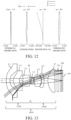
- FIGs. 1 , 5 , 9 , and 13 illustrate optical systems 100 (100A, 100B, 100C, and 100D) according to Examples 1, 2, 3, and 4, respectively.
- the optical system 100 according to each example is suitable for an image pickup apparatus such as a digital still camera, a digital video camera, an in-vehicle camera, a smartphone camera, a surveillance camera, a wearable camera, and a medical camera.
- a left side is an enlargement conjugate side (object side)
- a right side is a reduction conjugate side (image side).
- the optical system 100 according to each example is an imaging optical system that collects a light beam from an unillustrated object located on the enlargement conjugate side to form an object image on the image plane 300 on the reduction conjugate side.
- an imaging plane (light receiving surface) of an image sensor such as a CCD sensor and a CMOS sensor is disposed on the image plane.
- the optical system according to each example is a projection optical system of a projector that projects a light beam from a spatial light modulation element such as a liquid crystal panel disposed on the reduction conjugate side onto a projected surface such as a screen disposed on the enlargement conjugate side.
- the optical system is used as an imaging optical system of an in-vehicle camera.
- the optical system 100 includes, in order from an enlargement conjugate side to a reduction conjugate side, a front unit 101 (101A to 101D) having a plurality of lenses, an aperture stop (aperture stop) ST, and a rear unit 102 (102A to 102D) having a plurality of lenses.
- An IR cut filter 201 and a cover glass 202 are disposed between the optical system 100 and an image plane 300.
- a low-pass filter or the like may be additionally disposed as needed, or the IR cut filter 201 or the like may be omitted.
- An aperture stop for limiting an off-axis light beam may be disposed between the front unit 101 and the aperture stop ST and between the aperture stop ST and the rear unit 102, respectively.
- the front unit 101A includes four lenses L1, L2, L3, and L4.
- the rear unit 102A includes four lenses L5, L6, L7, and L8.
- the lens L1 closest to the enlargement conjugate position in the front unit 101A (optical system 100A) is an aspherical lens (first aspherical lens) having aspherical surfaces on both the enlargement conjugate side and the reduction conjugate side.
- the paraxial refractive power (paraxial power) is negative.
- the second lens L2 counted from the enlargement conjugate side in the front unit 101A is an aspherical lens (second aspherical lens) having aspherical surfaces on both sides and a positive paraxial refractive power.
- the third and fourth lenses L3 and L4 counted from the enlargement conjugate side in the front unit 101A are spherical lenses having negative and positive refractive powers, respectively.
- the lenses L5, L6, and L7 which are a lens closest to the enlargement conjugate position, and the second and third lenses counted from the enlargement conjugate side in the rear unit 102A, are spherical lenses having negative, positive, and negative refractive powers, respectively.
- the lens (final lens) L8 closest to the reduction conjugate position in the rear unit 102A (optical system 100A) is an aspherical lens (third aspherical lens) having aspherical surfaces on both sides and a positive paraxial refractive power.
- the optical system 100A includes no cemented lens and includes only single lenses.
- In-vehicle cameras may be placed in a high temperature environment (such as 70 °C or higher) exposed to direct sunlight in summer, and may be placed in a low temperature environment below zero in winter. Therefore, the cemented lens may cause peeling due to a difference in coefficient of linear expansion between cemented lens materials in the cemented lens, and thus only single lenses are used.
- Table 1 summarizes a numerical example of the optical system 100A according to this example.
- (A) indicates a lens configuration, f denotes a paraxial focal length (also simply referred to as a focal length hereinafter) (mm), and Fno denotes an F-number.
- ⁇ max denotes a maximum half angle of view (°).
- a radius of curvature r (mm) of an i-th plane, a distance d (mm) between an i-th plane and an (i+1) plane, a refractive index n for the d-line of each optical element, and an Abbe number v based on the d-line of each optical element are indicated in order from the enlargement conjugate side.
- h is a coordinate in a radial direction from the optical axis
- z is a coordinate (sag amount) in the optical axis direction
- r is a paraxial radius of curvature
- k is a conical constant.
- a sign of z is positive in a direction from the enlargement conjugate side to the reduction conjugate side.
- (B) illustrates the conical constant k of each aspherical surface, and aspherical coefficients B4, B6, B8, B10, B12, B14, and B16.
- E ⁇ x means "10 ⁇ x .” All aspherical coefficients not specifically described are 0. The description of this numerical example is the same in other examples described later.
- the optical system 100A according to this example is an optical system in which an imaging magnification of the angle of view area near the center (referred to as a central angle of view area hereinafter) is larger than that of the fisheye lens.
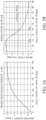
- FIGs. 2A and 2B illustrate the projection characteristic and the resolution characteristic of the optical system 100A according to this example, respectively.
- ° (deg) is used as a unit of the angle of view.
- the projection characteristic y( ⁇ ) illustrated in FIG. 2(A) illustrates a relationship between a half angle of view (an angle formed by the optical axis and the incident light ray) ⁇ and an imaging height (image height) y on the image plane 300.
- FIG. 2B illustrates a change amount in the imaging height y for a minute angle of view change at the half angle of view ⁇ , that is, a differential value dy( ⁇ )/d ⁇ at the half angle of view ⁇ of the projection characteristic y( ⁇ ).
- the differential value dy( ⁇ )/d ⁇ corresponds to a local resolution at the imaging height y, and the larger the value is, the higher the local resolution is.
- the high local resolution means a large local imaging magnification.
- the resolution in the following description means this local resolution.
- the optical system 100A is characterized in that its projection characteristic y( ⁇ ) satisfies the following inequality (conditional expression) (2): 1 ⁇ f ⁇ sin ⁇ max y ⁇ max ⁇ 1.9 where f denotes a focal length of the optical system 100A, and ⁇ max denotes a maximum half angle of view.
- the value is higher than the upper limit in the expression (2), the resolution near the center becomes too high, and it becomes difficult to obtain an angle of view equivalent to that of the fisheye lens.
- the angle of view equivalent to that of the fisheye lens can be obtained, a good optical performance may not be secured in a high angle of view area.
- the numerical range of the inequality (2) may be set as follows. 1 ⁇ f ⁇ sin ⁇ max y ⁇ max ⁇ 1.7
- the numerical range of the inequality (2) may be set as follows. 1 ⁇ f ⁇ sin ⁇ max y ⁇ max ⁇ 1.4
- the maximum half angle of view ⁇ max may satisfy the following inequality (3).
- the radian is used as the unit of the angle of view. ⁇ max ⁇ ⁇ 7 18
- a resolution higher than an on-axis resolution (at an angle of view 0) can be obtained in the low angle of view area.
- the optical distortion is suppressed in the low angle of view area, the distortion near the center of the captured image is decreased, so that the detection accuracy of other vehicles such as the preceding vehicle and the following vehicle can be improved.
- a captured image in the low angle of view area is displayed on a monitor instead of a rearview mirror, a natural perspective can be visually obtained, and the electronic distortion correction becomes unnecessary or a correcting amount can be reduced. Therefore, a good visibility can be obtained while the image deterioration is suppressed.
- the resolution in the low angle of view area increases as the angle of view increases from the optical axis, and the resolution in the high angle of view area decreases as the angle of view increases.
- the resolution has a local maximum value at a half angle of view ⁇ a, which is a boundary between the low angle of view area and the high angle of view area.
- the optical system 100A is configured so that the resolution has a local maximum value at the half angle of view ⁇ a
- a projection characteristic can be realized in which the resolution increases in the low angle of view area and the resolution decreases in the high angle of view area as the angle of view increases.
- the half angle of view ⁇ a at which the resolution (differential value dy( ⁇ )/d ⁇ ) has the local maximum value may satisfy the following inequality (4). 0.15 ⁇ ⁇ a ⁇ max ⁇ 0.35
- the low angle of view area having a high resolution becomes too narrow. If the value is higher than the upper limit in the inequality (4), the low angle of view area having a high resolution becomes too wide, and it becomes difficult to obtain an angle of view equivalent to that of the fisheye lens or it becomes difficult to secure a good optical performance in a high angle of view area even when the angle of view equivalent to that of the fisheye lens is obtained.
- the numerical range of the inequality (4) may be set as follows. 0.15 ⁇ ⁇ a ⁇ max ⁇ 0.30
- the numerical range of the inequality (4) may be set as follows. 0.16 ⁇ ⁇ a ⁇ max ⁇ 0.25
- the projection characteristic y( ⁇ ) of the optical system 100A may satisfy the following inequality (5): y ⁇ ⁇ > f
- the right side of the inequality (6) is a value obtained by dividing the maximum imaging height y( ⁇ max) by the maximum half angle of view ⁇ max, and represents an average resolution. Therefore, the half angle of view ⁇ b is a half angle of view at which the actual resolution is equal to the average resolution.
- the value is lower than the lower limit in the inequality (7), the low angle of view area having a high resolution becomes too narrow. If the value is higher than the upper limit in the inequality (7), it becomes difficult to obtain a wide angle of view equivalent to that of the fisheye lens, or it becomes difficult to secure a good optical performance in a high angle of view area even if the wide angle of view equivalent to that of the fisheye lens can be obtained.
- the numerical range of the inequality (7) may be set as follows. 0.4 ⁇ ⁇ b ⁇ max ⁇ 0.5
- the resolution is 0 at the outermost peripheral angle of view (at the maximum half angle of view ⁇ max).
- the resolution at the outermost peripheral angle of view of 0 is not suitable for the in-vehicle camera that is used to monitor the surroundings of the vehicle.
- the optical system 100A according to this example is configured so as to secure a resolution higher than a certain value rather than 0 even at the outermost peripheral angle of view when the maximum half angle of view ⁇ max is ⁇ /2.
- the resolution (differential value dy( ⁇ )/d ⁇ ) at the angle of view (outermost peripheral angle of view) ⁇ corresponding to the maximum half angle of view ⁇ max may satisfy the following inequality (8): 0.03 ⁇ dy ⁇ d ⁇ f ⁇ 0.15
- the resolution at the outermost peripheral angle of view becomes too low. If the value is higher than the upper limit in the inequality (8), the resolution at the outermost peripheral angle of view becomes high, and the angle of view area having a high resolution becomes too narrow.
- the numerical range of the inequality (8) may be set as follows. 0.03 ⁇ dy ⁇ d ⁇ f ⁇ 0.12
- the numerical range of the inequality (8) may be set as follows. 0.03 ⁇ dy ⁇ d ⁇ f ⁇ 0.10
- the front unit 101A disposed on the enlargement conjugate side of the aperture stop ST includes the first aspherical lens L1.
- the first aspherical lens L1 can satisfactorily correct the off-axis aberration such as a curvature of field.
- the first aspherical lens L1 may have a negative paraxial refractive power. This configuration can easily correct the off-axis aberration with a wide angle of view equivalent to that of the fisheye lens.
- the optical system 100A may include a second aspherical lens L2 on the reduction conjugate side of the first aspherical lens L1 in order to more effectively correct the off-axis aberration.
- the second aspherical lens L2 may have a positive paraxial refractive power. This configuration can easily correct the off-axis aberration while increasing the central resolution.
- Each of the first aspherical lens L1 and the second aspherical lens L2 may be a meniscus-shaped lens having a convex surface facing the object side. This is advantageous in correcting the curvature of field.
- FIG. 3 illustrates the curvatures of the aspherical surfaces (first surface, second surface) of the lens L1 and the aspherical surfaces (third surface, fourth surface) of the lens L2 for each radial position.
- part surrounded by a broken line circle indicates an inflection point (a circle centered on the optical axis because it is a radial position) in which positive and negative signs of the curvature are reversed.
- the projection characteristic in the low angle of view area is made closer to f ⁇ tan ⁇ , and the optical distortion becomes easily suppressed.
- the resolution at the maximum half angle of view ⁇ max can be easily made high.
- the refractive index n 1 of the lens L1 for the d-line may satisfy the following inequality (9). n 1 1.6 ⁇ 1.0
- the lens L1 Since the lens L1 has a meniscus shape in which the surface on the enlargement conjugate side is a convex surface, if the refractive index of the lens L1 is low so as not to satisfy the inequality (9), the processing difficulty becomes higher because the sag amount of the meniscus shape and the aspherical surface amount increase. This is also not preferable in terms of the miniaturization such as shortening the optical path length and reducing the diameter of the optical system.
- the refractive index n 2 of the lens L2 for the d-line may satisfy the following inequality (10). n 2 n 1 > 1.0
- the lens L1 has a negative paraxial refractive power
- the lens L2 has a positive paraxial refractive power
- the refractive index n 2 of the lens L2 may be larger than the refractive index n 1 of the lens L1.
- the (paraxial) focal length fa of the front unit 101A may satisfy the following inequality (11). f f a ⁇ 0.9
- the central resolution becomes lower than that of the fisheye lens of the orthogonal projection method, and it becomes difficult to obtain the wide angle of view equivalent to that of the fisheye lens, or to secure a good optical performance in the high angle of view area even when the wide angle of view equivalent to that of the fisheye lens can be obtained.
- the lens L4 closest to the reduction conjugate position in the front unit 101A may be a lens with a convex surface facing the reduction conjugate side.
- the coma occurs when the light beam is significantly bent by the lens L1, but the lens L4 may be the above lens for better corrections of the coma.
- the lens L8 closest to the reduction conjugate position in the rear unit 102A may have a positive refractive power. Since the lens L8 is a lens closest to the reduction conjugate side having a large off-axis light beam height, the incident angle of the light ray on the image plane 300 in the high angle of view area can be reduced when the lens L8 has the positive refractive power. As a result, a wide angle of view equivalent to that of the fisheye lens can be easily obtained while securing a good optical performance and a high central resolution.
- the lens L8 may be an aspherical lens because it is effective for better corrections of the off-axis aberration such as a curvature of field.
- the aspherical lens needs a positive refractive power in the periphery in order to maintain the effect of reducing the incident angle of the light ray on the image plane 300 in the high angle of view area.
- the lens L6 and the lens L7 disposed on the enlargement conjugate side of the lens L8 may have positive and negative refractive powers, respectively.
- the focal length of the rear unit 102A as a whole needs to be positive. Therefore, the rear unit 102A needs a lens having a positive refractive power, but if the refractive powers of all lenses constituting the rear unit 102A are positive, for example, the spherical aberrations that occur in all the lenses constituting the rear unit 102A are summed up.
- the lens L8 when the lens L8 has a positive refractive power, it is more effective to dispose a lens having a negative refractive power at a position where the height of the off-axis light ray is large in order to correct the off-axis aberration.
- the refractive power of the lens L6 on the enlargement conjugate side may be positive and the refractive power of the lens L7 on the reduction conjugate side may be negative.
- the refractive power of the lens L5 may be determined according to the sign of the focal length fa of the front unit 102A. In this example, since the focal length fa of the front unit 102A is positive, the refractive power of the lens L5 is set negative. Thereby, the residual spherical aberration of the front unit 102A can be corrected by the lens L5, and it becomes easier to obtain a better optical performance.
- the lens L8 has an effect of reducing the incident angle of the light ray on the image plane 300 in the high angle of view area. Accordingly, the following inequality (12) may be satisfied: 0.4 ⁇ D L ⁇ 0.6 where D is a distance on the optical axis from the aperture stop ST to the surface on the reduction conjugate side of the lens L8, and L is an overall length of the optical system 100A (a distance from the surface on the enlargement conjugate side of the lens L1 to the surface on the reduction conjugate side of the lens L8).
- This inequality (12) can increase the height of the off-axis light ray in the lens L8 while reducing the size of the optical system 100A in the radial direction.
- the value is higher than the upper limit in the inequality (12)
- the height of the off-axis light ray in the lens L8 can be easily increased because the aperture stop ST is located on the enlargement conjugate side, but the diameter of the lens L8 becomes large.
- the value is lower than the lower limit in the inequality (12)
- the numerical range of the inequality (12) may be set as follows. 0.4 ⁇ D L ⁇ 0.5
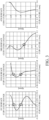
- FIG. 4 illustrates the longitudinal aberrations (spherical aberration, astigmatism, distortion, and lateral chromatic aberration) of the optical system 100A according to this example.
- Fno denotes an F-number
- a solid line denotes the spherical aberration for the d-line (wavelength 587.6 nm)
- an alternate long and two short dashes line denotes the spherical aberration for the C-line (wavelength 656.3 nm)
- an alternate long and short dash line denotes the spherical aberration for the F-line (wavelength 486.1 nm), respectively.
- a solid line S denotes a sagittal image plane
- a broken line M denotes a meridional image plane.
- a difference between the sagittal image plane and the meridional image plane is the astigmatism, each undulation denotes the curvature of field.
- the distortion is illustrated for the d-line.
- the chromatic aberration diagram denotes the lateral chromatic aberrations for the C-line and F-line.
- ⁇ is a half angle of view (°).
- a horizontal axis of the spherical aberration diagram and the astigmatism diagram is set to ⁇ 0.2 mm
- a horizontal axis of the distortion diagram is set to ⁇ 100%
- a horizontal axis of the chromatic aberration diagram is set to ⁇ 0.01 mm.
- the description of these aberration diagrams is the same in the other examples described later.
- the spherical aberration, the curvature of field, the astigmatism, and the lateral chromatic aberration are satisfactorily corrected.
- the distortion is small in the low angle of view area and increases in the high angle of view area as the imaging height increases.
- Table 2 summarizes parameter values in this example (numerical example) and the values of each of the above inequalities (except for the inequality (5)).
- the optical system 100A according to this example satisfies all of the inequalities. Therefore, the optical system 100A according to this example has a high central resolution, a wide angle of view equivalent to that of the fisheye lens, and a good optical performance.
- the basic configuration of the optical system 100B according to Example 2 illustrated in FIG. 5 is the same as that of the optical system 100A according to Example 1, and the components corresponding to those of the optical system 100A according to Example 1 will be designated by the same reference numerals.
- the front unit 101B includes four lenses L1 to L4.
- the lens L1 is an aspherical lens (first aspherical lens) having aspherical surfaces on both sides, and has a negative paraxial refractive power.
- the lens L2 is an aspherical lens (second aspherical lens) having aspherical surfaces on both sides, and has a positive paraxial refractive power.
- the lenses L3 and L4 are spherical lenses, and have negative and positive refractive powers, respectively.
- the rear unit 102B includes four lenses L5 to L8.
- the lenses L5, L6, and L7 are spherical lenses, and have positive, positive, and negative refractive powers, respectively.
- the sign of the refractive power of the lens L5 is different from that according to Example 1 because the sign of the focal length fa of the front unit 101A in this example is opposite to that of Example 1.
- the lens L8 is an aspherical lens (third aspherical lens) including aspherical surfaces on both sides, and has a positive paraxial refractive power.
- the lens L8 has a positive refractive power also in the periphery as in Example 1.
- the optical system 100B according to this example is an optical system having a maximum half angle of view ⁇ max of ⁇ /2, which is a maximum half angle of view equivalent to that of the fisheye lens.
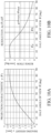
- FIGs. 6A and 6B illustrate the projection characteristic and the resolution characteristic of the optical system 100B according to this example, respectively.
- the optical system 100B according to this example has a wide angle of view equivalent to that of the fisheye lens, and a central resolution higher than that of the fisheye lens.
- FIG. 7 illustrates the curvatures of the aspherical surfaces (first surface, second surface) of the lens L1 and the aspherical surfaces (third surface, fourth surface) of the lens L2 for each radial position.
- the first, second, and third surfaces have inflection points
- the second and third surfaces have two inflection points.
- the surfaces having two inflection points are different from those of Example 1, the obtained effect is the same.
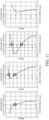
- FIG. 8 illustrates the longitudinal aberration of the optical system 100B according to this example.
- the spherical aberration, the curvature of field, the astigmatism, and the lateral chromatic aberration are satisfactorily corrected.
- the distortion is small in the low angle of view area and increases in the high angle of view area as the imaging height increases.
- Table 4 summarizes parameter values in this example (numerical example) and the values of each of the above inequalities (except for the inequality (5)).
- the optical system 100B according to this example satisfies all of the inequalities. Therefore, the optical system 100B according to this example has a high central resolution, a wide angle of view equivalent to that of the fisheye lens, and a good optical performance.
- the optical system 100C according to Example 3 illustrated in FIG. 9 is different from that of each of Examples 1 and 2 in that the front unit 100C includes a cover glass lens GL closest to the enlargement conjugate position and three lenses L1 to L3.
- the cover glass lens GL serves as a cover glass for protecting the lens L1 and a lens having a refractive power. Therefore, without the cover glass lens GL, the optical performance of the optical system 100C cannot be secured.
- the cover glass lens GL is designed to be insensitive to the arrangement errors so that it can be easily replaced if it gets damaged or scratched.
- the lens L1 is an aspherical lens (first aspherical lens) including aspherical surfaces on both sides, and has a negative paraxial refractive power.
- the lens L2 is an aspherical lens (second aspherical lens) having aspherical surfaces on both sides, and has a positive paraxial refractive power.
- the lens L3 is a spherical lens and has a negative refractive power.
- the rear unit 102C includes four lenses L4 to L7.
- the lenses L4, L5, and L6 are spherical lenses, and have positive, positive, and negative refractive powers, respectively.
- the lens L7 as the final lens is an aspherical lens (third aspherical lens) with aspherical surfaces on both sides, and has a positive paraxial refractive power.
- the lens L7 has a positive refractive power in the periphery similar to the lens L8 in Examples 1 and 2.
- the front unit 101C includes four lenses including the cover glass lens GL in order to suppress an increase in the overall length of the optical system 100C due to the provision of the cover glass lens GL.
- the lens L3 closest to the reduction conjugate position in the front unit 101C has a negative refractive power, and a convex surface facing the reduction conjugate side similar to Examples 1 and 2, satisfactorily correcting the coma.
- the optical system 100C according to this example is an optical system having a maximum half angle of view ⁇ max of ⁇ /2, which has a maximum half angle of view equivalent to that of the fisheye lens.
- FIGs. 10A and 10B illustrate the projection characteristic and the resolution characteristic of the optical system 100C according to this example, respectively.
- the optical system 100C according to this example has a wide angle of view equivalent to that of the fisheye lens, and a higher central resolution than that of fisheye lens.
- FIG. 11 illustrates the curvatures of the aspherical surfaces (third surface, fourth surface) of the lens L1 and the aspherical surfaces (fifth surface, sixth surface) of the lens L2 for each radial position.
- the third, fourth, and fifth surfaces have inflection points
- the fourth and fifth surfaces have two inflection points.
- the surfaces having two inflection points are different from those of Example 1, the obtained effect is the same.
- FIG. 12 illustrates the longitudinal aberration of the optical system 100C according to this example.
- the spherical aberration, the curvature of field, the astigmatism, and the lateral chromatic aberration are satisfactorily corrected.
- the distortion is small in the low angle of view area and increases in the high angle of view area as the imaging height increases.
- Table 6 summarizes parameter values in this example (numerical example) and the values of each of the above inequalities (except for the inequality (5)).
- the optical system 100C according to this example satisfies all of the inequalities. Therefore, the optical system 100C according to this example has a high central resolution, a wide angle of view equivalent to that of the fisheye lens, and a good optical performance.
- the optical system 100D according to Example 4 illustrated in FIG. 13 is different from the other examples in having no third aspherical lens and the spherical lens L7 disposed closest to the reduction conjugate position in the rear unit 102D.
- the front unit 101D includes three lenses L1 to L3.
- the lens L1 is an aspherical lens (first aspherical lens) having aspherical surfaces on both sides, and has a negative paraxial refractive power.
- the lens L2 is an aspherical lens (second aspherical lens) having aspherical surfaces on both sides, and has a positive paraxial refractive power.
- the lens L3 is a spherical lens and has a positive refractive power.
- the rear unit 102D includes four lenses L4 to L7.
- the lenses L4 to L7 are spherical lenses, and have positive, positive, negative, and positive refractive powers.
- the front unit 101D includes three lenses, and the spherical lens (final lens) L7 having a positive refractive power is disposed in the rear unit 102D instead of the third aspherical lens.
- the lens L7 as the spherical lens has a positive refractive power even in the periphery.
- This lens L7 may be provided in order to reduce the incident angle of the light ray on the image plane 300 in the high angle of view area and to obtain a high central resolution and a wide angle of view equivalent to that of the fisheye lens.
- the lens L3 closest to the reduction conjugate position in the front unit 101D has a convex surface facing the reduction conjugate side, satisfactorily correcting the coma similar to the other examples.
- the optical system 100D according to this example is an optical system having a maximum half angle of view ⁇ max of ⁇ /2, which has a maximum half angle of view equivalent to that of the fisheye lens.
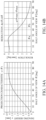
- FIGs. 14A and 14B illustrate the projection characteristic and the resolution characteristic of the optical system 100D according to this example, respectively.
- the optical system 100D according to this example has a wide angle of view equivalent to that of the fisheye lens, and a higher central resolution than that of the fisheye lens.
- FIG. 15 illustrates the curvatures of the aspherical surfaces (first surface, second surface) of the lens L1 and the aspherical surfaces (third surface, fourth surface) of the lens L2 for each radial position.
- the first, second, and third surfaces have inflection points
- the second and third surfaces have two inflection points.
- the surfaces having two inflection points are different from those of Example 1, the obtained effect is the same.
- FIG. 16 illustrates the longitudinal aberration of the optical system 100D according to this example.
- the spherical aberration, the curvature of field, the astigmatism, and the lateral chromatic aberration are satisfactorily corrected.
- the distortion is also small in the low angle of view area and increases in the high angle of view area as the imaging height increases.
- Table 8 summarizes parameter values in this example (numerical example) and the values of each of the above inequalities (except for the inequality (5)).
- the optical system 100D according to this example satisfies all of the inequalities. Therefore, the optical system 100D according to this example has a high central resolution, a wide angle of view equivalent to that of the fisheye lens, and a good optical performance.
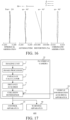
- FIG. 15 illustrates a configuration of an in-vehicle camera 10 using the optical system according to any one of the above examples for an imaging optical system, and an in-vehicle system (driving support device) 600 having the same.
- the in-vehicle system 600 is a system held by a moving body (moving apparatus) that is movable such as an automobile (vehicle), and configured to support driving (steering) of the vehicle based on image information around the vehicle acquired by the in-vehicle camera 10.
- FIG. 16 illustrates a vehicle 700 as a moving apparatus that includes the in-vehicle system 600. While FIG. 16 illustrates an imaging range 50 of the in-vehicle camera 10 set to the front of the vehicle 700, the imaging range 50 may be set to the rear or side of the vehicle 700.
- the in-vehicle system 600 includes the in-vehicle camera 10, a vehicle information acquiring apparatus 20, a control apparatus (controller, ECU: electronic control unit) 30, and a warning apparatus (warning unit) 40.
- the in-vehicle camera 10 includes an imaging unit 1, an image processor 2, a parallax calculator 3, a distance acquirer 4, and a collision determiner 5.
- the image processor 2, the parallax calculator 3, the distance acquirer 4, and the collision determiner 5 constitute a processing unit.
- the imaging unit 1 includes the optical system according to any one of the above examples and an image sensor.
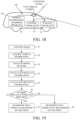
- a flowchart of FIG. 17 illustrates an operation example of the in-vehicle system 600.
- the in-vehicle system 600 images, using the imaging unit 1, an object such as an obstacle or a pedestrian around the vehicle, and acquires a plurality of image data (parallax image data).
- vehicle information is acquired by the vehicle information acquiring apparatus 20.
- the vehicle information is information including a vehicle speed, a yaw rate, a steering angle, and the like of the vehicle.
- the image processor 2 performs image processing for the plurality of image data acquired by the imaging unit 1. More specifically, the image feature analysis is performed to analyze a feature amount such as an edge amount, an edge direction, and a density value in image data. The image feature analysis may be performed for each of the plurality of image data, or may be performed only for part of the plurality of image data.
- the parallax calculator 3 calculates the parallax (image shift) information between the plurality of image data acquired by the imaging unit 1.
- a method for calculating the parallax information can use a known method such as the SSDA method or the area correlation method, and a description thereof will be omitted.
- the steps S2, S3, and S4 may be performed in this order, or may be processed in parallel.
- the distance acquirer 4 acquires (calculates) the distance information with the object imaged by the imaging unit 1.
- the distance information can be calculated based on the parallax information calculated by the parallax calculator 3 and the internal parameters and external parameters of the imaging unit 1.
- the distance information is information on a relative position with the object such as a distance from the object, a defocus amount, an image shift amount, etc., and may directly represent the distance value of the object in the image or indirectly represent information corresponding to the distance value.
- the collision determiner 5 determines whether or not the distance to the object is included in the preset distance range using the vehicle information acquired by the vehicle information acquiring apparatus 20 or the distance information calculated by the distance acquirer 4. This configuration can determine whether or not the object exists within the set distance around the vehicle, and determine a likelihood of collision between the vehicle and the object.
- the collision determiner 5 determines that "there is a likelihood of collision" (step 7) when the object exists within the set distance, and determines that there is no likelihood of collision (step 8) when the object does not exist within the set distance.
- the collision determiner 5 determines that "there is a likelihood of collision," the collision determiner 5 notifies (transmits) the determination result to the control apparatus 30 and the warning apparatus 40.
- the control apparatus 30 controls the vehicle based on the determination result of the collision determiner 5 (step S6), and the warning apparatus 40 provides warning to the vehicle user (driver, passenger) (step 7) based on the determination result of the collision determiner 5.
- the notification of the determination result may be made to at least one of the control apparatus 30 and the warning apparatus 40.
- the control apparatus 30 can control moving of the vehicle by outputting a control signal to a driving unit (engine, motor, etc.) in the vehicle.
- a driving unit engine, motor, etc.
- the control apparatus 30 generates a control signal for hitting the brakes, returning the gas pedal, turning the steering wheel, and applying the braking force to each wheel in the vehicle, and makes a control over the vehicle to suppress an output of the engine or the motor.
- the warning apparatus 40 gives a warning to the user, for example, by issuing a warning sound (alert), displaying warning information on a screen of a car navigation system, or giving vibrations to the seat belt or steering wheel.
- the above processing can effectively detect the object and avoid a collision between the vehicle and the object.
- the entire in-vehicle camera 10 can be made smaller with an improved freedom degree of the arrangement, detect the object, and determine the likelihood of collision at a wide angle of view.
- a pupil dividing type image sensor that includes a plurality of pixel units regularly arranged in a two-dimensional array is used for the image sensor in the imaging unit 1.
- one pixel unit includes a microlens and a plurality of photoelectric conversion units, receives a pair of light beams that have passed through different areas in the pupil of the optical system, and outputs a pair of image data from each photoelectric conversion unit.
- An image shift amount of each area is calculated by the correlation calculation between the pair of image data, and the image shift map data representing a distribution of the image shift amount is calculated by the distance acquirer 4.
- the distance acquirer 4 may further convert the image shift amount into a defocus amount and generate defocus map data representing a distribution of the defocus amount (distribution on the two-dimensional plane of the captured image).
- the distance acquirer 4 may acquire the distance map data of the distance to the object converted from the defocus amount.
- Each of the in-vehicle system 600 and the mobile apparatus 700 may include a notification apparatus (notifier) configured to notify the manufacturer of the in-vehicle system, the seller (dealer) of the moving apparatus, and the like of the fact that the moving apparatus 700 has collided with the obstacle.
- the notification apparatus can use a device that transmits information (collision information) on a collision between the moving apparatus 700 and the obstacle to a preset external notification destination by e-mail or the like.
- the notification destination of the collision information may be an arbitrary destination set by the user, such as an insurance company, a medical institution, and the police.
- the notification apparatus may be configured so as to notify not only the collision information but also the failure information of each component and consumption information of consumables.
- the presence or absence of the collision may be detected by using the distance information acquired based on the output from the imaging unit 1 described above, or by another detector (sensor).
- the in-vehicle system 600 is applied to a driving support (collision damage reduction), but the present invention is not limited to this example, and the in-vehicle system 600 is applicable to the cruise control (including adaptive cruise control) and automatic driving.
- the in-vehicle system 600 is applicable not only to a vehicle such as an automobile but also to a moving body such as a ship, an aircraft, or an industrial robot. It is applicable not only to the moving body but also to various devices that utilize an object recognition such as an intelligent transportation system (ITS).
- ITS intelligent transportation system
- Embodiment(s) of the present invention can also be realized by a computer of a system or apparatus that reads out and executes computer executable instructions (e.g., one or more programs) recorded on a storage medium (which may also be referred to more fully as a 'non-transitory computer-readable storage medium') to perform the functions of one or more of the above-described embodiment(s) and/or that includes one or more circuits (e.g., application specific integrated circuit (ASIC)) for performing the functions of one or more of the above-described embodiment(s), and by a method performed by the computer of the system or apparatus by, for example, reading out and executing the computer executable instructions from the storage medium to perform the functions of one or more of the above-described embodiment(s) and/or controlling the one or more circuits to perform the functions of one or more of the above-described embodiment(s).
- computer executable instructions e.g., one or more programs
- a storage medium which may also be referred to more fully as
- the computer may comprise one or more processors (e.g., central processing unit (CPU), micro processing unit (MPU)) and may include a network of separate computers or separate processors to read out and execute the computer executable instructions.
- the computer executable instructions may be provided to the computer, for example, from a network or the storage medium.
- the storage medium may include, for example, one or more of a hard disk, a random-access memory (RAM), a read only memory (ROM), a storage of distributed computing systems, an optical disk (such as a compact disc (CD), digital versatile disc (DVD), or Blu-ray Disc (BD) TM ), a flash memory device, a memory card, and the like.
- Each example can provide an optical system that has a sufficient angle of view and a sufficient imaging magnification in a central angle of view area, and makes small an image pickup apparatus.
Landscapes
- Physics & Mathematics (AREA)
- General Physics & Mathematics (AREA)
- Optics & Photonics (AREA)
- Engineering & Computer Science (AREA)
- Mechanical Engineering (AREA)
- Theoretical Computer Science (AREA)
- Transportation (AREA)
- Computer Vision & Pattern Recognition (AREA)
- Automation & Control Theory (AREA)
- Business, Economics & Management (AREA)
- Emergency Management (AREA)
- Multimedia (AREA)
- Lenses (AREA)
- Studio Devices (AREA)
- Fittings On The Vehicle Exterior For Carrying Loads, And Devices For Holding Or Mounting Articles (AREA)
- Control Of Driving Devices And Active Controlling Of Vehicle (AREA)
- Traffic Control Systems (AREA)
Claims (29)
- Optisches System (100A bis 100D), das in der Reihenfolge von einer konjugierten Vergrößerungsseite zu einer konjugierten Verkleinerungsseite eine vordere Einheit (101A bis 101D) mit mehreren Linsen, eine Aperturblende (ST) und eine hintere Einheit (102A bis 1020) mit mehreren Linsen, umfasst,dadurch gekennzeichnet, dass eine Projektionscharakteristik y(θ) des optischen Systems, die eine Beziehung zwischen einem Bildhalbwinkel θ und einer Bildhöhe y auf einer Bildebene darstellt, die folgende Ungleichung erfüllt:
 wobei ein Differenzwert dy(θ)/dθ bei dem Bildhalbwinkel θ der Projektionscharakteristik y(θ) einen lokalen Maximalwert aufweist.
 - Optisches System nach Anspruch 1, dadurch gekennzeichnet, dass die folgende Ungleichung erfüllt ist:

- Optisches System nach Anspruch 1 oder 2, dadurch gekennzeichnet, dass die folgende Ungleichung erfüllt ist:
- Optisches System nach einem der Ansprüche 1 bis 3, dadurch gekennzeichnet, dass die folgende Ungleichung erfüllt ist:

- Optisches System nach einem der Ansprüche 1 bis 4, dadurch gekennzeichnet, dass der Differenzwert dy(θ)/dθ die folgende Ungleichung erfüllt:

- Optisches System nach einem der Ansprüche 1 bis 5, dadurch gekennzeichnet, dass die vordere Einheit eine erste asphärische Linse (L1) enthält.
- Optisches System nach Anspruch 6, dadurch gekennzeichnet, dass die erste asphärische Linse eine negative paraxiale Brechkraft aufweist.
- Optisches System nach Anspruch 6 oder 7, dadurch gekennzeichnet, dass die erste asphärische Linse eine Meniskusform mit einer konvexen Fläche, die der konjugierten Vergrößerungsseite zugewandt ist, aufweist.
- Optisches System nach einem der Ansprüche 6 bis 8, dadurch gekennzeichnet, dass die folgende Bedingungsungleichung erfüllt ist:

- Optisches System nach einem der Ansprüche 6 bis 9, dadurch gekennzeichnet, dass die vordere Einheit eine zweite asphärische Linse (L2) enthält, die auf der konjugierten Verkleinerungsseite der ersten asphärischen Linse angeordnet ist.
- Optisches System nach Anspruch 10, dadurch gekennzeichnet, dass die zweite asphärische Linse eine positive paraxiale Brechkraft aufweist.
- Optisches System nach Anspruch 10 oder 11, dadurch gekennzeichnet, dass die zweite asphärische Linse eine Meniskusform mit einer konvexen Fläche, die der konjugierten Vergrößerungsseite zugewandt ist, aufweist.
- Optisches System nach einem der Ansprüche 10 bis 12, dadurch gekennzeichnet, dass die folgende Ungleichung erfüllt ist:

- Optisches System nach einem der Ansprüche 10 bis 13, dadurch gekennzeichnet, dass eine jeweilige der ersten asphärischen Linse und der zweiten asphärischen Linse eine asphärische Fläche mit einem Wendepunkt enthält.
- Optisches System nach Anspruch 14, dadurch gekennzeichnet, dass wenigstens eine der ersten asphärischen Linse und der zweiten asphärischen Linse eine asphärische Fläche mit mehreren Wendepunkten enthält.
- Optisches System nach einem der Ansprüche 1 bis 15, dadurch gekennzeichnet, dass die folgende Ungleichung erfüllt ist:

- Optisches System nach einem der Ansprüche 1 bis 16, dadurch gekennzeichnet, dass eine Linse, die einer konjugierten Verkleinerungsposition am nächsten ist, eine positive paraxiale Brechkraft und eine positive Brechkraft bei einem Randbereich aufweist.
- Optisches System nach einem der Ansprüche 1 bis 17, dadurch gekennzeichnet, dass die folgende Ungleichung erfüllt ist:

- Optisches System nach einem der Ansprüche 1 bis 18, dadurch gekennzeichnet, dass die folgende Ungleichung erfüllt ist:

- Bildaufnahmevorrichtung (10), umfassend:das optische System nach einem der Ansprüche 1 bis 19; undeinen Bildsensor, der konfiguriert ist, ein Objekt über das optische System abzubilden.
- Fahrzeuginternes System (600), umfassend:die Bildaufnahmevorrichtung (10) nach Anspruch 20; undeinen Bestimmer (5), der konfiguriert ist, eine Kollisionswahrscheinlichkeit zwischen einem Fahrzeug und dem Objekt basierend auf Abstandsinformation des Objekts, die von der Bildaufnahmevorrichtung erfasst wird, zu bestimmen.
- Fahrzeuginternes System nach Anspruch 21, ferner umfassend eine Steuervorrichtung, die konfiguriert ist, ein Steuersignal auszugeben, das eine Bremskraft an einer Antriebseinheit des Fahrzeugs erzeugt, wenn bestimmt wird, dass es eine Kollisionswahrscheinlichkeit zwischen dem Fahrzeug und dem Objekt gibt.
- Fahrzeuginternes System nach Anspruch 21, ferner umfassend eine Warnvorrichtung, die konfiguriert ist, einen Benutzer des Fahrzeugs zu warnen, wenn bestimmt wird, dass es eine Kollisionswahrscheinlichkeit zwischen dem Fahrzeug und dem Objekt gibt.
- Fahrzeuginternes System nach Anspruch 21, ferner umfassend eine Benachrichtigungsvorrichtung, die konfiguriert ist, einen Benutzer über Information über eine Kollision zwischen dem Fahrzeug und dem Objekt zu benachrichtigen.
- Sich bewegende Vorrichtung (700), umfassend die Bildaufnahmevorrichtung (10) nach Anspruch 20 und bewegbar, während sie die Bildaufnahmevorrichtung hält.
- Sich bewegende Vorrichtung nach Anspruch 25, ferner umfassend einen Bestimmer (5), der konfiguriert ist, eine Kollisionswahrscheinlichkeit zwischen einem Fahrzeug und dem Objekt basierend auf Abstandsinformation des Objekts, die von der Bildaufnahmevorrichtung erfasst wird, zu bestimmen.
- Sich bewegende Vorrichtung nach Anspruch 25 oder 26, ferner umfassend eine Steuervorrichtung (30), die konfiguriert ist, ein Steuersignal auszugeben, das eine Bremskraft an einer Antriebseinheit des Fahrzeugs erzeugt, wenn bestimmt wird, dass es eine Kollisionswahrscheinlichkeit zwischen dem Fahrzeug und dem Objekt gibt.
- Sich bewegende Vorrichtung nach einem der Ansprüche 25 bis 27, ferner umfassend eine Warnvorrichtung (40), die konfiguriert ist, einen Benutzer des Fahrzeugs zu warnen, wenn bestimmt wird, dass es eine Kollisionswahrscheinlichkeit zwischen dem Fahrzeug und dem Objekt gibt.
- Sich bewegende Vorrichtung nach einem der Ansprüche 25 bis 28, ferner umfassend eine Benachrichtigungsvorrichtung, die konfiguriert ist, einen Benutzer über Information über eine Kollision zwischen dem Fahrzeug und dem Objekt zu benachrichtigen.
Applications Claiming Priority (1)
| Application Number | Priority Date | Filing Date | Title |
|---|---|---|---|
| JP2021011189A JP7187590B2 (ja) | 2021-01-27 | 2021-01-27 | 光学系、撮像装置、車載システムおよび移動装置 |
Publications (3)
| Publication Number | Publication Date |
|---|---|
| EP4036626A1 EP4036626A1 (de) | 2022-08-03 |
| EP4036626B1 true EP4036626B1 (de) | 2023-12-20 |
| EP4036626C0 EP4036626C0 (de) | 2023-12-20 |
Family
ID=80001263
Family Applications (1)
| Application Number | Title | Priority Date | Filing Date |
|---|---|---|---|
| EP22152955.5A Active EP4036626B1 (de) | 2021-01-27 | 2022-01-24 | Weitwinkelobjektiv |
Country Status (4)
| Country | Link |
|---|---|
| US (2) | US12392995B2 (de) |
| EP (1) | EP4036626B1 (de) |
| JP (3) | JP7187590B2 (de) |
| CN (2) | CN119471980A (de) |
Families Citing this family (12)
| Publication number | Priority date | Publication date | Assignee | Title |
|---|---|---|---|---|
| JP7187590B2 (ja) | 2021-01-27 | 2022-12-12 | キヤノン株式会社 | 光学系、撮像装置、車載システムおよび移動装置 |
| TWI808492B (zh) | 2021-09-17 | 2023-07-11 | 大立光電股份有限公司 | 光學攝像系統組及取像裝置 |
| JP7799506B2 (ja) | 2022-02-18 | 2026-01-15 | キヤノン株式会社 | ズームレンズおよび撮像装置 |
| CN115421348A (zh) * | 2022-09-21 | 2022-12-02 | 西安应用光学研究所 | 一种具有加热功能的8mp车载镜头 |
| JP2024048085A (ja) * | 2022-09-27 | 2024-04-08 | キヤノン株式会社 | 測距装置、車載システム、および移動装置 |
| EP4345522A1 (de) * | 2022-09-30 | 2024-04-03 | Samsung Electro-Mechanics Co., Ltd. | Linsensystem für bildgebung |
| JP2024077842A (ja) * | 2022-11-29 | 2024-06-10 | キヤノン株式会社 | 光学系、それを備える撮像装置及び車載システム |
| US12566320B2 (en) | 2023-06-13 | 2026-03-03 | Bae Systems Information And Electronic Systems Integration Inc. | Panoramic MWIR lens for cooled detectors |
| TWI864912B (zh) * | 2023-07-27 | 2024-12-01 | 今國光學工業股份有限公司 | 八片式攝像鏡頭 |
| US12477205B1 (en) * | 2023-09-06 | 2025-11-18 | Waymo Llc | Foveated imager for automotive applications |
| CN117991477B (zh) * | 2024-03-21 | 2025-09-16 | 江西特莱斯光学有限公司 | 一种大靶面超星光列车舱内监控光学系统 |
| CN119126351B (zh) * | 2024-09-25 | 2025-09-30 | 东莞市融光光学有限公司 | 一种全景镜头 |
Family Cites Families (24)
| Publication number | Priority date | Publication date | Assignee | Title |
|---|---|---|---|---|
| JP2004354572A (ja) | 2003-05-28 | 2004-12-16 | Minolta Co Ltd | 撮像装置 |
| JP2006343545A (ja) * | 2005-06-09 | 2006-12-21 | Auto Network Gijutsu Kenkyusho:Kk | カメラ装置及び車両周辺監視装置 |
| JP4683212B2 (ja) | 2005-12-02 | 2011-05-18 | 株式会社ニコン | 魚眼レンズ及び撮像装置 |
| JP5363084B2 (ja) | 2008-12-01 | 2013-12-11 | 富士フイルム株式会社 | 投写用魚眼レンズおよびこれを用いた投写型表示装置 |
| JP5724755B2 (ja) * | 2011-08-26 | 2015-05-27 | 株式会社リコー | 撮像システム |
| JP6370127B2 (ja) | 2014-06-24 | 2018-08-08 | キヤノン株式会社 | 結像光学素子及びそれを備える光走査装置 |
| WO2016068095A1 (ja) * | 2014-10-29 | 2016-05-06 | 日立オートモティブシステムズ株式会社 | 光学系、撮像装置および距離測定システム |
| JP6545997B2 (ja) * | 2015-04-24 | 2019-07-17 | 日立オートモティブシステムズ株式会社 | 画像処理装置 |
| JP6212528B2 (ja) | 2015-11-06 | 2017-10-11 | キヤノン株式会社 | 光走査装置 |
| JP2017092752A (ja) * | 2015-11-12 | 2017-05-25 | トヨタ自動車株式会社 | 撮像システム |
| US20170153430A1 (en) | 2015-11-27 | 2017-06-01 | Canon Kabushiki Kaisha | Projection lens and image projection apparatus |
| JP6746328B2 (ja) * | 2016-03-04 | 2020-08-26 | キヤノン株式会社 | 光学系、それを備える撮像装置及び投影装置 |
| KR102710801B1 (ko) * | 2016-08-03 | 2024-09-27 | 삼성전자주식회사 | 옵티칼 렌즈 어셈블리 및 이를 포함한 전자 장치 |
| JP6759161B2 (ja) | 2017-07-06 | 2020-09-23 | キヤノン株式会社 | 光学系および画像投射装置 |
| JP6873877B2 (ja) | 2017-09-25 | 2021-05-19 | キヤノン株式会社 | 光学系、および画投影装置 |
| JP6918731B2 (ja) | 2018-02-28 | 2021-08-11 | キヤノン株式会社 | 光学系及び撮像装置 |
| CN112119282A (zh) * | 2018-03-23 | 2020-12-22 | 索尼公司 | 信息处理装置、移动装置、方法和程序 |
| JP7207038B2 (ja) * | 2019-03-14 | 2023-01-18 | 株式会社リコー | 撮像装置、撮像光学系及び移動体 |
| JP7288192B2 (ja) * | 2019-07-05 | 2023-06-07 | テイ・エス テック株式会社 | シート |
| JP2021067703A (ja) | 2019-10-17 | 2021-04-30 | キヤノン株式会社 | 結像光学系およびそれを有する画像投影装置 |
| JP2021071502A (ja) | 2019-10-29 | 2021-05-06 | キヤノン株式会社 | 光学系、投射レンズ、画像投射装置および撮像レンズ |
| JP2022028242A (ja) * | 2020-08-03 | 2022-02-16 | 株式会社リコー | 撮像光学系、撮像装置、ステレオカメラ装置及び情報処理装置 |
| JP7187590B2 (ja) | 2021-01-27 | 2022-12-12 | キヤノン株式会社 | 光学系、撮像装置、車載システムおよび移動装置 |
| CN113470618A (zh) * | 2021-06-08 | 2021-10-01 | 阿波罗智联(北京)科技有限公司 | 唤醒测试的方法、装置、电子设备和可读存储介质 |
-
2021
- 2021-01-27 JP JP2021011189A patent/JP7187590B2/ja active Active
-
2022
- 2022-01-21 US US17/580,891 patent/US12392995B2/en active Active
- 2022-01-24 EP EP22152955.5A patent/EP4036626B1/de active Active
- 2022-01-26 CN CN202411899769.1A patent/CN119471980A/zh active Pending
- 2022-01-26 CN CN202210093283.3A patent/CN114815142B/zh active Active
- 2022-11-25 JP JP2022187977A patent/JP7635192B2/ja active Active
-
2025
- 2025-02-13 JP JP2025021444A patent/JP2025071122A/ja active Pending
- 2025-07-29 US US19/283,444 patent/US20250355227A1/en active Pending
Also Published As
| Publication number | Publication date |
|---|---|
| US12392995B2 (en) | 2025-08-19 |
| EP4036626C0 (de) | 2023-12-20 |
| JP7635192B2 (ja) | 2025-02-25 |
| JP2022114766A (ja) | 2022-08-08 |
| CN114815142B (zh) | 2025-01-07 |
| JP7187590B2 (ja) | 2022-12-12 |
| JP2023016888A (ja) | 2023-02-02 |
| JP2025071122A (ja) | 2025-05-02 |
| US20250355227A1 (en) | 2025-11-20 |
| EP4036626A1 (de) | 2022-08-03 |
| CN114815142A (zh) | 2022-07-29 |
| CN119471980A (zh) | 2025-02-18 |
| US20220236541A1 (en) | 2022-07-28 |
Similar Documents
| Publication | Publication Date | Title |
|---|---|---|
| EP4036626B1 (de) | Weitwinkelobjektiv | |
| JP6746328B2 (ja) | 光学系、それを備える撮像装置及び投影装置 | |
| WO2017150486A1 (ja) | 光学系、それを備える撮像装置及び投影装置 | |
| WO2017150493A1 (ja) | 撮像装置及び投影装置 | |
| US12038565B2 (en) | Optical system, image pickup apparatus, in-vehicle system, and moving apparatus | |
| CN109307929B (zh) | 带折射面和反射面的光学系统与图像拍摄装置和投影装置 | |
| EP4036625B1 (de) | Optisches system, bildaufnahmevorrichtung, fahrzeuginternes system und bewegungsvorrichtung | |
| CN117581142A (zh) | 图像拾取系统 | |
| CN117561468A (zh) | 光学系统、图像拾取装置和图像拾取系统 | |
| JP2023183790A (ja) | 光学系、撮像装置、車載システム、および移動装置 | |
| JP2018189747A (ja) | 光学系、それを備える撮像装置及び投影装置 | |
| CN113448064B (zh) | 光学系统、图像拾取装置、车载系统和移动装置 | |
| JP7635006B2 (ja) | 光学系、撮像装置、車載システムおよび移動装置 | |
| JP2021081663A (ja) | 光学系及びそれを備える撮像装置 | |
| JP7379112B2 (ja) | 光学系及びそれを備える撮像装置 | |
| JP2025089713A (ja) | 光学系及びそれを備える撮像装置 | |
| JP2023111409A (ja) | 撮像レンズ系、及びそれを用いたカメラモジュール、車載システム、移動体 | |
| WO2017150492A1 (ja) | 光学系、それを備える撮像装置及び投影装置 | |
| JP2019045819A (ja) | 光学系、それを備える撮像装置及び投影装置 |
Legal Events
| Date | Code | Title | Description |
|---|---|---|---|
| PUAI | Public reference made under article 153(3) epc to a published international application that has entered the european phase |
Free format text: ORIGINAL CODE: 0009012 |
|
| STAA | Information on the status of an ep patent application or granted ep patent |
Free format text: STATUS: THE APPLICATION HAS BEEN PUBLISHED |
|
| AK | Designated contracting states |
Kind code of ref document: A1 Designated state(s): AL AT BE BG CH CY CZ DE DK EE ES FI FR GB GR HR HU IE IS IT LI LT LU LV MC MK MT NL NO PL PT RO RS SE SI SK SM TR |
|
| STAA | Information on the status of an ep patent application or granted ep patent |
Free format text: STATUS: REQUEST FOR EXAMINATION WAS MADE |
|
| 17P | Request for examination filed |
Effective date: 20230203 |
|
| RBV | Designated contracting states (corrected) |
Designated state(s): AL AT BE BG CH CY CZ DE DK EE ES FI FR GB GR HR HU IE IS IT LI LT LU LV MC MK MT NL NO PL PT RO RS SE SI SK SM TR |
|
| GRAP | Despatch of communication of intention to grant a patent |
Free format text: ORIGINAL CODE: EPIDOSNIGR1 |
|
| STAA | Information on the status of an ep patent application or granted ep patent |
Free format text: STATUS: GRANT OF PATENT IS INTENDED |
|
| RIC1 | Information provided on ipc code assigned before grant |
Ipc: G02B 13/00 20060101ALI20230606BHEP Ipc: G02B 9/64 20060101ALI20230606BHEP Ipc: G02B 13/06 20060101AFI20230606BHEP |
|
| INTG | Intention to grant announced |
Effective date: 20230711 |
|
| GRAS | Grant fee paid |
Free format text: ORIGINAL CODE: EPIDOSNIGR3 |
|
| GRAA | (expected) grant |
Free format text: ORIGINAL CODE: 0009210 |
|
| STAA | Information on the status of an ep patent application or granted ep patent |
Free format text: STATUS: THE PATENT HAS BEEN GRANTED |
|
| AK | Designated contracting states |
Kind code of ref document: B1 Designated state(s): AL AT BE BG CH CY CZ DE DK EE ES FI FR GB GR HR HU IE IS IT LI LT LU LV MC MK MT NL NO PL PT RO RS SE SI SK SM TR |
|
| REG | Reference to a national code |
Ref country code: GB Ref legal event code: FG4D |
|
| REG | Reference to a national code |
Ref country code: CH Ref legal event code: EP |
|
| REG | Reference to a national code |
Ref country code: DE Ref legal event code: R096 Ref document number: 602022001311 Country of ref document: DE |
|
| REG | Reference to a national code |
Ref country code: IE Ref legal event code: FG4D |
|
| U01 | Request for unitary effect filed |
Effective date: 20240115 |
|
| U07 | Unitary effect registered |
Designated state(s): AT BE BG DE DK EE FI FR IT LT LU LV MT NL PT SE SI Effective date: 20240124 |
|
| U20 | Renewal fee for the european patent with unitary effect paid |
Year of fee payment: 3 Effective date: 20240131 |
|
| PG25 | Lapsed in a contracting state [announced via postgrant information from national office to epo] |
Ref country code: GR Free format text: LAPSE BECAUSE OF FAILURE TO SUBMIT A TRANSLATION OF THE DESCRIPTION OR TO PAY THE FEE WITHIN THE PRESCRIBED TIME-LIMIT Effective date: 20240321 |
|
| PG25 | Lapsed in a contracting state [announced via postgrant information from national office to epo] |
Ref country code: ES Free format text: LAPSE BECAUSE OF FAILURE TO SUBMIT A TRANSLATION OF THE DESCRIPTION OR TO PAY THE FEE WITHIN THE PRESCRIBED TIME-LIMIT Effective date: 20231220 |
|
| PG25 | Lapsed in a contracting state [announced via postgrant information from national office to epo] |
Ref country code: GR Free format text: LAPSE BECAUSE OF FAILURE TO SUBMIT A TRANSLATION OF THE DESCRIPTION OR TO PAY THE FEE WITHIN THE PRESCRIBED TIME-LIMIT Effective date: 20240321 Ref country code: ES Free format text: LAPSE BECAUSE OF FAILURE TO SUBMIT A TRANSLATION OF THE DESCRIPTION OR TO PAY THE FEE WITHIN THE PRESCRIBED TIME-LIMIT Effective date: 20231220 |
|
| PG25 | Lapsed in a contracting state [announced via postgrant information from national office to epo] |
Ref country code: RS Free format text: LAPSE BECAUSE OF FAILURE TO SUBMIT A TRANSLATION OF THE DESCRIPTION OR TO PAY THE FEE WITHIN THE PRESCRIBED TIME-LIMIT Effective date: 20231220 Ref country code: NO Free format text: LAPSE BECAUSE OF FAILURE TO SUBMIT A TRANSLATION OF THE DESCRIPTION OR TO PAY THE FEE WITHIN THE PRESCRIBED TIME-LIMIT Effective date: 20240320 Ref country code: HR Free format text: LAPSE BECAUSE OF FAILURE TO SUBMIT A TRANSLATION OF THE DESCRIPTION OR TO PAY THE FEE WITHIN THE PRESCRIBED TIME-LIMIT Effective date: 20231220 |
|
| PG25 | Lapsed in a contracting state [announced via postgrant information from national office to epo] |
Ref country code: IS Free format text: LAPSE BECAUSE OF FAILURE TO SUBMIT A TRANSLATION OF THE DESCRIPTION OR TO PAY THE FEE WITHIN THE PRESCRIBED TIME-LIMIT Effective date: 20240420 |
|
| PG25 | Lapsed in a contracting state [announced via postgrant information from national office to epo] |
Ref country code: CZ Free format text: LAPSE BECAUSE OF FAILURE TO SUBMIT A TRANSLATION OF THE DESCRIPTION OR TO PAY THE FEE WITHIN THE PRESCRIBED TIME-LIMIT Effective date: 20231220 |
|
| PG25 | Lapsed in a contracting state [announced via postgrant information from national office to epo] |
Ref country code: SK Free format text: LAPSE BECAUSE OF FAILURE TO SUBMIT A TRANSLATION OF THE DESCRIPTION OR TO PAY THE FEE WITHIN THE PRESCRIBED TIME-LIMIT Effective date: 20231220 |
|
| PG25 | Lapsed in a contracting state [announced via postgrant information from national office to epo] |
Ref country code: SM Free format text: LAPSE BECAUSE OF FAILURE TO SUBMIT A TRANSLATION OF THE DESCRIPTION OR TO PAY THE FEE WITHIN THE PRESCRIBED TIME-LIMIT Effective date: 20231220 Ref country code: SK Free format text: LAPSE BECAUSE OF FAILURE TO SUBMIT A TRANSLATION OF THE DESCRIPTION OR TO PAY THE FEE WITHIN THE PRESCRIBED TIME-LIMIT Effective date: 20231220 Ref country code: RO Free format text: LAPSE BECAUSE OF FAILURE TO SUBMIT A TRANSLATION OF THE DESCRIPTION OR TO PAY THE FEE WITHIN THE PRESCRIBED TIME-LIMIT Effective date: 20231220 Ref country code: IS Free format text: LAPSE BECAUSE OF FAILURE TO SUBMIT A TRANSLATION OF THE DESCRIPTION OR TO PAY THE FEE WITHIN THE PRESCRIBED TIME-LIMIT Effective date: 20240420 Ref country code: CZ Free format text: LAPSE BECAUSE OF FAILURE TO SUBMIT A TRANSLATION OF THE DESCRIPTION OR TO PAY THE FEE WITHIN THE PRESCRIBED TIME-LIMIT Effective date: 20231220 |
|
| PG25 | Lapsed in a contracting state [announced via postgrant information from national office to epo] |
Ref country code: PL Free format text: LAPSE BECAUSE OF FAILURE TO SUBMIT A TRANSLATION OF THE DESCRIPTION OR TO PAY THE FEE WITHIN THE PRESCRIBED TIME-LIMIT Effective date: 20231220 |
|
| PG25 | Lapsed in a contracting state [announced via postgrant information from national office to epo] |
Ref country code: PL Free format text: LAPSE BECAUSE OF FAILURE TO SUBMIT A TRANSLATION OF THE DESCRIPTION OR TO PAY THE FEE WITHIN THE PRESCRIBED TIME-LIMIT Effective date: 20231220 |
|
| REG | Reference to a national code |
Ref country code: DE Ref legal event code: R097 Ref document number: 602022001311 Country of ref document: DE |
|
| PG25 | Lapsed in a contracting state [announced via postgrant information from national office to epo] |
Ref country code: MC Free format text: LAPSE BECAUSE OF FAILURE TO SUBMIT A TRANSLATION OF THE DESCRIPTION OR TO PAY THE FEE WITHIN THE PRESCRIBED TIME-LIMIT Effective date: 20231220 |
|
| PLBE | No opposition filed within time limit |
Free format text: ORIGINAL CODE: 0009261 |
|
| STAA | Information on the status of an ep patent application or granted ep patent |
Free format text: STATUS: NO OPPOSITION FILED WITHIN TIME LIMIT |
|
| 26N | No opposition filed |
Effective date: 20240923 |
|
| U20 | Renewal fee for the european patent with unitary effect paid |
Year of fee payment: 4 Effective date: 20241218 |
|
| PG25 | Lapsed in a contracting state [announced via postgrant information from national office to epo] |
Ref country code: IE Free format text: LAPSE BECAUSE OF NON-PAYMENT OF DUE FEES Effective date: 20240124 |
|
| PG25 | Lapsed in a contracting state [announced via postgrant information from national office to epo] |
Ref country code: IE Free format text: LAPSE BECAUSE OF NON-PAYMENT OF DUE FEES Effective date: 20240124 |
|
| PG25 | Lapsed in a contracting state [announced via postgrant information from national office to epo] |
Ref country code: CY Free format text: LAPSE BECAUSE OF FAILURE TO SUBMIT A TRANSLATION OF THE DESCRIPTION OR TO PAY THE FEE WITHIN THE PRESCRIBED TIME-LIMIT; INVALID AB INITIO Effective date: 20220124 |
|
| REG | Reference to a national code |
Ref country code: CH Ref legal event code: PL |
|
| PG25 | Lapsed in a contracting state [announced via postgrant information from national office to epo] |
Ref country code: CH Free format text: LAPSE BECAUSE OF NON-PAYMENT OF DUE FEES Effective date: 20250131 |
|
| PG25 | Lapsed in a contracting state [announced via postgrant information from national office to epo] |
Ref country code: TR Free format text: LAPSE BECAUSE OF FAILURE TO SUBMIT A TRANSLATION OF THE DESCRIPTION OR TO PAY THE FEE WITHIN THE PRESCRIBED TIME-LIMIT Effective date: 20231220 |
|
| U20 | Renewal fee for the european patent with unitary effect paid |
Year of fee payment: 5 Effective date: 20251217 |