EP4028697B1 - Entfeuchtungssystem - Google Patents
Entfeuchtungssystem Download PDFInfo
- Publication number
- EP4028697B1 EP4028697B1 EP20863061.6A EP20863061A EP4028697B1 EP 4028697 B1 EP4028697 B1 EP 4028697B1 EP 20863061 A EP20863061 A EP 20863061A EP 4028697 B1 EP4028697 B1 EP 4028697B1
- Authority
- EP
- European Patent Office
- Prior art keywords
- cooling fluid
- cooling
- fluid
- process air
- heat exchanger
- Prior art date
- Legal status (The legal status is an assumption and is not a legal conclusion. Google has not performed a legal analysis and makes no representation as to the accuracy of the status listed.)
- Active
Links
Images


Classifications
-
- B—PERFORMING OPERATIONS; TRANSPORTING
- B01—PHYSICAL OR CHEMICAL PROCESSES OR APPARATUS IN GENERAL
- B01D—SEPARATION
- B01D53/00—Separation of gases or vapours; Recovering vapours of volatile solvents from gases; Chemical or biological purification of waste gases, e.g. engine exhaust gases, smoke, fumes, flue gases, aerosols
- B01D53/26—Drying gases or vapours
- B01D53/261—Drying gases or vapours by adsorption
-
- F—MECHANICAL ENGINEERING; LIGHTING; HEATING; WEAPONS; BLASTING
- F24—HEATING; RANGES; VENTILATING
- F24F—AIR-CONDITIONING; AIR-HUMIDIFICATION; VENTILATION; USE OF AIR CURRENTS FOR SCREENING
- F24F11/00—Control or safety arrangements
- F24F11/0008—Control or safety arrangements for air-humidification
-
- F—MECHANICAL ENGINEERING; LIGHTING; HEATING; WEAPONS; BLASTING
- F24—HEATING; RANGES; VENTILATING
- F24F—AIR-CONDITIONING; AIR-HUMIDIFICATION; VENTILATION; USE OF AIR CURRENTS FOR SCREENING
- F24F11/00—Control or safety arrangements
- F24F11/30—Control or safety arrangements for purposes related to the operation of the system, e.g. for safety or monitoring
-
- F—MECHANICAL ENGINEERING; LIGHTING; HEATING; WEAPONS; BLASTING
- F24—HEATING; RANGES; VENTILATING
- F24F—AIR-CONDITIONING; AIR-HUMIDIFICATION; VENTILATION; USE OF AIR CURRENTS FOR SCREENING
- F24F11/00—Control or safety arrangements
- F24F11/70—Control systems characterised by their outputs; Constructional details thereof
- F24F11/80—Control systems characterised by their outputs; Constructional details thereof for controlling the temperature of the supplied air
- F24F11/83—Control systems characterised by their outputs; Constructional details thereof for controlling the temperature of the supplied air by controlling the supply of heat-exchange fluids to heat-exchangers
- F24F11/84—Control systems characterised by their outputs; Constructional details thereof for controlling the temperature of the supplied air by controlling the supply of heat-exchange fluids to heat-exchangers using valves
-
- F—MECHANICAL ENGINEERING; LIGHTING; HEATING; WEAPONS; BLASTING
- F24—HEATING; RANGES; VENTILATING
- F24F—AIR-CONDITIONING; AIR-HUMIDIFICATION; VENTILATION; USE OF AIR CURRENTS FOR SCREENING
- F24F12/00—Use of energy recovery systems in air conditioning, ventilation or screening
- F24F12/001—Use of energy recovery systems in air conditioning, ventilation or screening with heat-exchange between supplied and exhausted air
- F24F12/002—Use of energy recovery systems in air conditioning, ventilation or screening with heat-exchange between supplied and exhausted air using an intermediate heat-transfer fluid
-
- F—MECHANICAL ENGINEERING; LIGHTING; HEATING; WEAPONS; BLASTING
- F24—HEATING; RANGES; VENTILATING
- F24F—AIR-CONDITIONING; AIR-HUMIDIFICATION; VENTILATION; USE OF AIR CURRENTS FOR SCREENING
- F24F3/00—Air-conditioning systems in which conditioned primary air is supplied from one or more central stations to distributing units in the rooms or spaces where it may receive secondary treatment; Apparatus specially designed for such systems
- F24F3/044—Systems in which all treatment is given in the central station, i.e. all-air systems
-
- F—MECHANICAL ENGINEERING; LIGHTING; HEATING; WEAPONS; BLASTING
- F24—HEATING; RANGES; VENTILATING
- F24F—AIR-CONDITIONING; AIR-HUMIDIFICATION; VENTILATION; USE OF AIR CURRENTS FOR SCREENING
- F24F3/00—Air-conditioning systems in which conditioned primary air is supplied from one or more central stations to distributing units in the rooms or spaces where it may receive secondary treatment; Apparatus specially designed for such systems
- F24F3/12—Air-conditioning systems in which conditioned primary air is supplied from one or more central stations to distributing units in the rooms or spaces where it may receive secondary treatment; Apparatus specially designed for such systems characterised by the treatment of the air otherwise than by heating and cooling
- F24F3/14—Air-conditioning systems in which conditioned primary air is supplied from one or more central stations to distributing units in the rooms or spaces where it may receive secondary treatment; Apparatus specially designed for such systems characterised by the treatment of the air otherwise than by heating and cooling by humidification; by dehumidification
- F24F3/1411—Air-conditioning systems in which conditioned primary air is supplied from one or more central stations to distributing units in the rooms or spaces where it may receive secondary treatment; Apparatus specially designed for such systems characterised by the treatment of the air otherwise than by heating and cooling by humidification; by dehumidification by absorbing or adsorbing water, e.g. using an hygroscopic desiccant
-
- F—MECHANICAL ENGINEERING; LIGHTING; HEATING; WEAPONS; BLASTING
- F24—HEATING; RANGES; VENTILATING
- F24F—AIR-CONDITIONING; AIR-HUMIDIFICATION; VENTILATION; USE OF AIR CURRENTS FOR SCREENING
- F24F3/00—Air-conditioning systems in which conditioned primary air is supplied from one or more central stations to distributing units in the rooms or spaces where it may receive secondary treatment; Apparatus specially designed for such systems
- F24F3/12—Air-conditioning systems in which conditioned primary air is supplied from one or more central stations to distributing units in the rooms or spaces where it may receive secondary treatment; Apparatus specially designed for such systems characterised by the treatment of the air otherwise than by heating and cooling
- F24F3/14—Air-conditioning systems in which conditioned primary air is supplied from one or more central stations to distributing units in the rooms or spaces where it may receive secondary treatment; Apparatus specially designed for such systems characterised by the treatment of the air otherwise than by heating and cooling by humidification; by dehumidification
- F24F3/147—Air-conditioning systems in which conditioned primary air is supplied from one or more central stations to distributing units in the rooms or spaces where it may receive secondary treatment; Apparatus specially designed for such systems characterised by the treatment of the air otherwise than by heating and cooling by humidification; by dehumidification with both heat and humidity transfer between supplied and exhausted air
-
- F—MECHANICAL ENGINEERING; LIGHTING; HEATING; WEAPONS; BLASTING
- F24—HEATING; RANGES; VENTILATING
- F24F—AIR-CONDITIONING; AIR-HUMIDIFICATION; VENTILATION; USE OF AIR CURRENTS FOR SCREENING
- F24F3/00—Air-conditioning systems in which conditioned primary air is supplied from one or more central stations to distributing units in the rooms or spaces where it may receive secondary treatment; Apparatus specially designed for such systems
- F24F3/12—Air-conditioning systems in which conditioned primary air is supplied from one or more central stations to distributing units in the rooms or spaces where it may receive secondary treatment; Apparatus specially designed for such systems characterised by the treatment of the air otherwise than by heating and cooling
- F24F3/14—Air-conditioning systems in which conditioned primary air is supplied from one or more central stations to distributing units in the rooms or spaces where it may receive secondary treatment; Apparatus specially designed for such systems characterised by the treatment of the air otherwise than by heating and cooling by humidification; by dehumidification
- F24F3/153—Air-conditioning systems in which conditioned primary air is supplied from one or more central stations to distributing units in the rooms or spaces where it may receive secondary treatment; Apparatus specially designed for such systems characterised by the treatment of the air otherwise than by heating and cooling by humidification; by dehumidification with subsequent heating, i.e. with the air, given the required humidity in the central station, passing a heating element to achieve the required temperature
-
- B—PERFORMING OPERATIONS; TRANSPORTING
- B01—PHYSICAL OR CHEMICAL PROCESSES OR APPARATUS IN GENERAL
- B01D—SEPARATION
- B01D53/00—Separation of gases or vapours; Recovering vapours of volatile solvents from gases; Chemical or biological purification of waste gases, e.g. engine exhaust gases, smoke, fumes, flue gases, aerosols
- B01D53/26—Drying gases or vapours
- B01D53/265—Drying gases or vapours by refrigeration (condensation)
-
- F—MECHANICAL ENGINEERING; LIGHTING; HEATING; WEAPONS; BLASTING
- F24—HEATING; RANGES; VENTILATING
- F24F—AIR-CONDITIONING; AIR-HUMIDIFICATION; VENTILATION; USE OF AIR CURRENTS FOR SCREENING
- F24F11/00—Control or safety arrangements
- F24F11/30—Control or safety arrangements for purposes related to the operation of the system, e.g. for safety or monitoring
- F24F11/46—Improving electric energy efficiency or saving
-
- F—MECHANICAL ENGINEERING; LIGHTING; HEATING; WEAPONS; BLASTING
- F24—HEATING; RANGES; VENTILATING
- F24F—AIR-CONDITIONING; AIR-HUMIDIFICATION; VENTILATION; USE OF AIR CURRENTS FOR SCREENING
- F24F3/00—Air-conditioning systems in which conditioned primary air is supplied from one or more central stations to distributing units in the rooms or spaces where it may receive secondary treatment; Apparatus specially designed for such systems
- F24F3/12—Air-conditioning systems in which conditioned primary air is supplied from one or more central stations to distributing units in the rooms or spaces where it may receive secondary treatment; Apparatus specially designed for such systems characterised by the treatment of the air otherwise than by heating and cooling
- F24F3/14—Air-conditioning systems in which conditioned primary air is supplied from one or more central stations to distributing units in the rooms or spaces where it may receive secondary treatment; Apparatus specially designed for such systems characterised by the treatment of the air otherwise than by heating and cooling by humidification; by dehumidification
- F24F2003/144—Air-conditioning systems in which conditioned primary air is supplied from one or more central stations to distributing units in the rooms or spaces where it may receive secondary treatment; Apparatus specially designed for such systems characterised by the treatment of the air otherwise than by heating and cooling by humidification; by dehumidification by dehumidification only
- F24F2003/1446—Air-conditioning systems in which conditioned primary air is supplied from one or more central stations to distributing units in the rooms or spaces where it may receive secondary treatment; Apparatus specially designed for such systems characterised by the treatment of the air otherwise than by heating and cooling by humidification; by dehumidification by dehumidification only by condensing
-
- F—MECHANICAL ENGINEERING; LIGHTING; HEATING; WEAPONS; BLASTING
- F24—HEATING; RANGES; VENTILATING
- F24F—AIR-CONDITIONING; AIR-HUMIDIFICATION; VENTILATION; USE OF AIR CURRENTS FOR SCREENING
- F24F3/00—Air-conditioning systems in which conditioned primary air is supplied from one or more central stations to distributing units in the rooms or spaces where it may receive secondary treatment; Apparatus specially designed for such systems
- F24F3/12—Air-conditioning systems in which conditioned primary air is supplied from one or more central stations to distributing units in the rooms or spaces where it may receive secondary treatment; Apparatus specially designed for such systems characterised by the treatment of the air otherwise than by heating and cooling
- F24F3/14—Air-conditioning systems in which conditioned primary air is supplied from one or more central stations to distributing units in the rooms or spaces where it may receive secondary treatment; Apparatus specially designed for such systems characterised by the treatment of the air otherwise than by heating and cooling by humidification; by dehumidification
- F24F2003/1458—Air-conditioning systems in which conditioned primary air is supplied from one or more central stations to distributing units in the rooms or spaces where it may receive secondary treatment; Apparatus specially designed for such systems characterised by the treatment of the air otherwise than by heating and cooling by humidification; by dehumidification using regenerators
-
- F—MECHANICAL ENGINEERING; LIGHTING; HEATING; WEAPONS; BLASTING
- F24—HEATING; RANGES; VENTILATING
- F24F—AIR-CONDITIONING; AIR-HUMIDIFICATION; VENTILATION; USE OF AIR CURRENTS FOR SCREENING
- F24F2110/00—Control inputs relating to air properties
- F24F2110/10—Temperature
-
- F—MECHANICAL ENGINEERING; LIGHTING; HEATING; WEAPONS; BLASTING
- F24—HEATING; RANGES; VENTILATING
- F24F—AIR-CONDITIONING; AIR-HUMIDIFICATION; VENTILATION; USE OF AIR CURRENTS FOR SCREENING
- F24F2140/00—Control inputs relating to system states
- F24F2140/20—Heat-exchange fluid temperature
-
- F—MECHANICAL ENGINEERING; LIGHTING; HEATING; WEAPONS; BLASTING
- F24—HEATING; RANGES; VENTILATING
- F24F—AIR-CONDITIONING; AIR-HUMIDIFICATION; VENTILATION; USE OF AIR CURRENTS FOR SCREENING
- F24F2203/00—Devices or apparatus used for air treatment
- F24F2203/10—Rotary wheel
- F24F2203/1016—Rotary wheel combined with another type of cooling principle, e.g. compression cycle
-
- F—MECHANICAL ENGINEERING; LIGHTING; HEATING; WEAPONS; BLASTING
- F24—HEATING; RANGES; VENTILATING
- F24F—AIR-CONDITIONING; AIR-HUMIDIFICATION; VENTILATION; USE OF AIR CURRENTS FOR SCREENING
- F24F2203/00—Devices or apparatus used for air treatment
- F24F2203/10—Rotary wheel
- F24F2203/1032—Desiccant wheel
-
- F—MECHANICAL ENGINEERING; LIGHTING; HEATING; WEAPONS; BLASTING
- F24—HEATING; RANGES; VENTILATING
- F24F—AIR-CONDITIONING; AIR-HUMIDIFICATION; VENTILATION; USE OF AIR CURRENTS FOR SCREENING
- F24F2203/00—Devices or apparatus used for air treatment
- F24F2203/10—Rotary wheel
- F24F2203/1056—Rotary wheel comprising a reheater
- F24F2203/106—Electrical reheater
-
- F—MECHANICAL ENGINEERING; LIGHTING; HEATING; WEAPONS; BLASTING
- F24—HEATING; RANGES; VENTILATING
- F24F—AIR-CONDITIONING; AIR-HUMIDIFICATION; VENTILATION; USE OF AIR CURRENTS FOR SCREENING
- F24F5/00—Air-conditioning systems or apparatus not covered by F24F1/00 or F24F3/00, e.g. using solar heat or combined with household units such as an oven or water heater
- F24F5/0003—Exclusively-fluid systems
-
- F—MECHANICAL ENGINEERING; LIGHTING; HEATING; WEAPONS; BLASTING
- F24—HEATING; RANGES; VENTILATING
- F24F—AIR-CONDITIONING; AIR-HUMIDIFICATION; VENTILATION; USE OF AIR CURRENTS FOR SCREENING
- F24F5/00—Air-conditioning systems or apparatus not covered by F24F1/00 or F24F3/00, e.g. using solar heat or combined with household units such as an oven or water heater
- F24F5/0007—Air-conditioning systems or apparatus not covered by F24F1/00 or F24F3/00, e.g. using solar heat or combined with household units such as an oven or water heater cooling apparatus specially adapted for use in air-conditioning
- F24F5/001—Compression cycle type
-
- Y—GENERAL TAGGING OF NEW TECHNOLOGICAL DEVELOPMENTS; GENERAL TAGGING OF CROSS-SECTIONAL TECHNOLOGIES SPANNING OVER SEVERAL SECTIONS OF THE IPC; TECHNICAL SUBJECTS COVERED BY FORMER USPC CROSS-REFERENCE ART COLLECTIONS [XRACs] AND DIGESTS
- Y02—TECHNOLOGIES OR APPLICATIONS FOR MITIGATION OR ADAPTATION AGAINST CLIMATE CHANGE
- Y02B—CLIMATE CHANGE MITIGATION TECHNOLOGIES RELATED TO BUILDINGS, e.g. HOUSING, HOUSE APPLIANCES OR RELATED END-USER APPLICATIONS
- Y02B30/00—Energy efficient heating, ventilation or air conditioning [HVAC]
- Y02B30/52—Heat recovery pumps, i.e. heat pump based systems or units able to transfer the thermal energy from one area of the premises or part of the facilities to a different one, improving the overall efficiency
-
- Y—GENERAL TAGGING OF NEW TECHNOLOGICAL DEVELOPMENTS; GENERAL TAGGING OF CROSS-SECTIONAL TECHNOLOGIES SPANNING OVER SEVERAL SECTIONS OF THE IPC; TECHNICAL SUBJECTS COVERED BY FORMER USPC CROSS-REFERENCE ART COLLECTIONS [XRACs] AND DIGESTS
- Y02—TECHNOLOGIES OR APPLICATIONS FOR MITIGATION OR ADAPTATION AGAINST CLIMATE CHANGE
- Y02B—CLIMATE CHANGE MITIGATION TECHNOLOGIES RELATED TO BUILDINGS, e.g. HOUSING, HOUSE APPLIANCES OR RELATED END-USER APPLICATIONS
- Y02B30/00—Energy efficient heating, ventilation or air conditioning [HVAC]
- Y02B30/56—Heat recovery units
Definitions
- the present invention relates to a dehumidification system, and a method of operating the dehumidification system.
- Dehumidifiers such as sorption dehumidifiers and condensate dehumidifiers, are used for separating and removing moisture from air.
- a sorption dehumidifier typically comprises a dehumidifying element in the form of a wheel or rotor holding desiccant material, which is effective in attracting and retaining water vapour.
- the desiccant rotor may be divided in two sections, a process section and a regeneration section.
- the airflow to be dehumidified, process air will pass through the process section of the desiccant rotor, the desiccant material in the rotor extracts moisture from the process air, so that it can leave the rotor as dried air.
- the desiccant material is regenerated by another air stream, which flows through the regeneration section, all the while the desiccant rotor may rotate slowly about its longitudinal axis.
- the dehumidifier can be operated continuously.
- US2007056307 discloses an example of a dehumidifier having a desiccant wheel.
- the air stream used for regeneration of the desiccant material in the rotor needs to have a relatively high temperature, and will typically need to be heated. It may be advantageous to cool the process air prior to the dehumidifier inlet, in order to remove moisture due to cooling.
- the heat subtracted from the process air flow during cooling can be transferred to the regeneration air stream by the provision of a heat pump in the dehumidification system.
- US2005/0050906A1 shows an example of this, where process air is cooled by the evaporator of a heat pump prior to the dehumidifier inlet, and the regeneration air is heated by the condenser of the heat pump.
- Document JP 2015 145000 A also discloses such a dehumidification system.
- the present invention aims at providing an energy effective dehumidification system, which allows for stable and reliable dehumidification of process air, as defined in the appended claims.
- the dehumidification system of the invention is defined in claim 1.
- it comprises a sorption dehumidifier unit; a process air circuit arranged to conduct a process air flow through desiccant material in the dehumidifier unit; a regeneration air circuit arranged to conduct a regeneration air flow through the desiccant material in the dehumidifier unit; and a heat pump comprising an evaporator and a condenser.
- the system further comprises an intermediate fluid circuit with a cooling fluid (C), arranged to cool the process air in a heat exchanger before inlet of the process air into the dehumidifier unit, said intermediate fluid circuit comprising a fluid pump and a main conduit arranged to conduct cooling fluid (C) through the process air cooling heat exchanger and through the evaporator of the heat pump, and the intermediate fluid circuit further comprising a flow control system arranged to control the flow of cooling fluid (C) in the intermediate fluid circuit to obtain a cooling fluid temperature dependent parameter value (T1) in the intermediate fluid circuit upstream of the process air cooling heat exchanger, which corresponds to a given set-point cooling fluid temperature dependent parameter value (T1 set ), wherein the flow control system includes a control unit (CU), and measuring equipment for determining the cooling fluid temperature dependent parameter value, wherein said measuring equipment is suitably arranged in the system in the flow conduit (8a) between the pump (11) and the process air cooling heat exchanger (9), and wherein means are provided for forwarding information of the determined parameter value (T1) to the control
- the cooling fluid temperature dependent parameter is preferably the cooling fluid temperature
- the given set-point value (T1 set ) for the cooling fluid preferably is set to a temperature below 10 °C, more preferably below 5 °C, most preferably below 0.5 °C.
- the process air cooling heat exchanger is advantageously dimensioned to cool the process air at the process air inlet of the dehumidifier unit to a given constant air inlet temperature value (T2), said air inlet temperature value (T2) preferably being below 10 °C.
- the regeneration air circuit is preferably connected to the condenser of the heat pump upstream of the dehumidifier unit.
- the intermediate fluid circuit preferably comprises a heat exchanger arranged upstream of the heat pump evaporator to cool the regeneration air downstream of the dehumidifier unit.
- the regeneration air circuit may comprise an electrical heater upstream of the dehumidifier unit, arranged to optionally heat the regeneration air if needed.
- the process air cooling heat exchanger (9) is advantageously dimensioned to cool the process air upstream of the process air inlet of the dehumidifier unit to a given constant air inlet temperature value (T2).
- T2 constant air inlet temperature value
- process air cooling heat exchanger (9) may be somewhat over-dimensioned at some points in time.
- a predetermined constant temperature of the process air entering the dehumidification unit can improve the dehumidification process, since the dehumidification unit can be optimised for inlet process air having certain predictable properties, and the operation of the dehumidification process will stable.
- the process air temperature value (T2) upstream of the dehumidification unit will be dependent on the given set-point value (T1 set ) for the cooling fluid temperature upstream of the process air cooling heat exchanger (9), and is preferably as low as possible, preferably below 10 °C, and suitably above 0 °C. Measurement of temperature dependent parameters in a fluid flow is stable and reliable, as compared to measuring similar parameters in an air flow, and controlling the dehumidification system based on the cooling fluid temperature (T1) upstream of the process air cooling heat exchanger (9) therefore leads to stable operation of the of the system.
- the properties of the process air entering the dehumidification system can vary substantially from time to time.
- these properties can vary largely due to seasonal variations and time of the day, and this can be particularly significant in certain geographical regions.
- the process air is taken from a confined space, such an industrial building, the properties can vary depending on various circumstances, such as the activities performed in the building, and the weather variations outside the building. Therefore, in order to obtain a constant temperature of the process air upstream of the dehumidifier unit, the process air cooling heat exchanger (9) will need to be dimensioned according to the specific circumstances of the site where the system is implemented.
- the cooling fluid temperature (T1) upstream of the process air cooling heat exchanger (9) is controlled by adjustment of the flow of cooling fluid in the intermediate fluid circuit.
- the flow control system of the intermediate fluid circuit comprises a control unit (CU) arranged to control the flow of cooling fluid in the intermediate fluid circuit (8), preferably by controlling the fluid pump (11) and/or one or more fluid control valves (12, 13) arranged in the intermediate fluid circuit.
- the fluid pump may suitably have a variable frequency drive to allow control the flow capacity of the pump, and/or one or more fluid control valves can be opened or closed as needed to obtain the cooling flow needed to keep the cooling fluid temperature (T1) at the set value (T1 set ).
- the flow of cooling fluid in the main conduit (8a) is at least partly indirectly controlled based on the need of cooling capacity in the process air cooling heat exchanger (9). If the temperature (T1) of cooling fluid upstream of the process air cooling heat exchanger (9) exceeds the set value (T1 set ), this will be detected by the control unit (CU), which will act on the fluid pump and/or the one or more fluid control valves to decrease the flow in the main conduit (8a), until the cooling fluid temperature (T1) has returned to the set value (T1 set ), and vice versa, if the temperature (T1) falls below the set value (T1 set ), the flow in the main conduit (8a) will increase.
- the control unit CU
- the intermediate fluid circuit may preferably comprise a bypass conduit (8b), suitably be provided with a fluid control valve (13), allowing a part of the cooling fluid (C) to bypass the process air cooling heat exchanger (9).
- a bypass conduit (8b) suitably be provided with a fluid control valve (13), allowing a part of the cooling fluid (C) to bypass the process air cooling heat exchanger (9).
- This increases the flexibility of the dehumidification system, since the cooling fluid flow in the main conduit (8a) of the intermediate fluid circuit can be controlled both by adjusting the flow capacity of the pump (11) and/or the fluid control valve (12) in the main conduit, and by letting a part of the cooling fluid flow bypass the heat exchanger (9) through the bypass conduit (8b), e.g. by opening the fluid control valve (13).
- the fluid control valves (12, 13) in the main conduit and the bypass conduit can of course be replaced by a three-way valve if desired.
- the dehumidification system comprises a regeneration air circuit (4) arranged to conduct a regeneration air flow through the desiccant material in the dehumidifier unit (2).
- the dehumidifier unit can be of any type suitable for dehumidification of process air by means of desiccant material and regeneration air.
- the sorption dehumidifier (2) can suitably comprise a dehumidifying element in the form of a rotor holding desiccant material, e.g. silica gel, which is effective in attracting and retaining water vapour.
- the desiccant rotor may be divided in two sections, a dehumidification section and a regeneration section.
- the process air (3) to be dehumidified will pass through the dehumidification section of the desiccant rotor, in which the desiccant material in the rotor extracts moisture from the process air, so that it can leave the rotor as dried air (3b). Simultaneously, the moisture-laden desiccant material is regenerated in a regeneration section, where the moisture is transferred to the regeneration air stream (4), which flows through the regeneration section, all while the desiccant rotor rotates slowly.
- the dehumidifier unit (2) can be operated continuously.
- dehumidifier unit can be contemplated, for example comprising multiple rotors holding desiccant material, rotors having more than two sections, and or in which one or both of the process air flow and the regeneration air flow are divided in multiple air streams within the dehumidifier unit.
- the dehumidifier unit need not necessarily be a single process unit, but can be comprised of multiple steps or sections in series or parallel.
- the air stream used for regeneration of the desiccant material in the rotor needs to have a relatively high temperature, and will typically need to be heated.
- the regeneration air circuit (4) can preferably be connected to the condenser (7) of the heat pump, upstream of the dehumidifier unit. This means that heat subtracted from the cooling fluid (C) in the heat pump evaporator (6) can be transferred to the inlet regeneration air (4a), via the refrigerant circuit (16) of the heat pump and the condenser, i.e.
- heat subtracted from the process air (3) in the air cooling heat exchanger (9) can be utilized for heating the inlet regeneration air (4a), via the intermediate fluid circuit (8) and the refrigerant circuit (16) of the heat pump (5).
- An electrical heater (15) may be comprised in the regeneration air circuit (4) upstream of the dehumidifier unit, arranged to optionally heat the inlet regeneration air (4a) if needed.
- a heat exchanger (14) is therefore suitably arranged on the outlet regeneration air flow to allow recovery of heat held therein.
- the heat exchanger (14) is preferably incorporated into the intermediate fluid circuit (8), and is then preferably arranged in the intermediate fluid circuit (8) upstream of the heat pump evaporator (6) so as to cool the regeneration air (4b) downstream of the dehumidifier unit, thus extracting heat from the regeneration air flow (4b).
- the outlet regeneration air (4b) can be returned to the regeneration air circuit (4), optionally after further removal of moisture, as regeneration inlet air (4a), so that the regeneration air circuit (4) is a closed circuit.
- the heat subtracted from the regeneration air (4b) in the heat exchanger (14) can thus be utilised to heat the inlet regeneration air (4a) by means of the heat pump (5).
- the heat of the regeneration air is suitably transferred to a cooling fluid, which may preferably be the cooling fluid (C) of the intermediate fluid circuit, as mentioned above, or a partial flow thereof, as shown in Fig. 2 .
- An outlet regeneration air heat exchanger (14) as described above can be particularly useful in situations where the heat transferred in the process air cooling heat exchanger (9), i.e. from the inlet process air (3) to the fluid (C) of the intermediate fluid circuit, does not match the energy requirement of the heat pump evaporator (6) needed to sufficiently heat the inlet regeneration air (4) in the heat pump condenser (7).
- Such situations may be for example when the temperature of the process air (3) entering the process air cooling heat exchanger (9) is low or when the outlet process air (3b) needs to be extra dry (e.g. dew point below -20°C), which may by the case in certain industrial processes.
- the outlet regeneration air heat exchanger (14) can then provide additional heating of the cooling fluid (C) in the intermediate fluid circuit, since the temperature (T6) of the outlet regeneration air is typically substantially higher than the temperature (T4) of the cooling fluid (C) leaving the process air cooling heat exchanger (9).
- the flow control system (10) is advantageously arranged to control the flow of cooling liquid (C) in the intermediate fluid circuit (11) so that the heat subtracted from the inlet process air (3a) in the process air cooling heat exchanger (9) and from the outlet regeneration air (4b) in the regeneration air heat exchanger (14) substantially corresponds to the heat required to be transferred to the inlet regeneration air (4a) in the condenser (7) of the heat pump in order to reach a given temperature (T3) at the regeneration air inlet of the dehumidifier unit (2), so as to substantially eliminate the need of additional heating by means of the electrical heater (15).
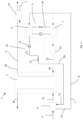
- FIG. 1 illustrates a first example of the dehumidification system (1) comprising an intermediate fluid circuit (11) which is used to control the cooling fluid temperature upstream of an inlet process air cooling heat exchanger.
- the heating of inlet regeneration air (4a) by the heat pump condenser (7) is also shown.
- the cooling fluid of the intermediate fluid circuit collects heat from outlet regeneration air downstream of the dehumidification unit.
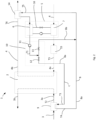
- Fig. 3 illustrates a third example of the dehumidification system, wherein the intermediate fluid circuit is arranged to provide a separate cooling fluid flow through the outlet regeneration air cooling heat exchanger.
- the present invention also relates to a method (100) of operating the above dehumidification system, comprising the steps of
- the method is preferably performed by a computer program for operating the above dehumidification system, comprising instructions which, when applied on the control unit of a dehumidification system according to the above-mentioned dehumidification system, and executed on at least one processor, causes the at least one processor to carry out the above method.
- the present invention also relates to a computer-readable storage medium carrying the computer program for operating the dehumidification system.
Landscapes
- Engineering & Computer Science (AREA)
- Chemical & Material Sciences (AREA)
- Combustion & Propulsion (AREA)
- Mechanical Engineering (AREA)
- General Engineering & Computer Science (AREA)
- General Chemical & Material Sciences (AREA)
- Analytical Chemistry (AREA)
- Oil, Petroleum & Natural Gas (AREA)
- Chemical Kinetics & Catalysis (AREA)
- Life Sciences & Earth Sciences (AREA)
- Sustainable Development (AREA)
- Thermal Sciences (AREA)
- Physics & Mathematics (AREA)
- Drying Of Gases (AREA)
- Central Air Conditioning (AREA)
- Air Conditioning Control Device (AREA)
Claims (10)
- Entfeuchtungssystem (1), umfassend- eine Sorptionsentfeuchtereinheit (2);- einen Prozessluftkreislauf (3), der angeordnet ist, um einen Prozessluftstrom durch Trocknungsmittelmaterial in der Entfeuchtereinheit (2) zu leiten;- einen Regenerationsluftkreislauf (4), der angeordnet ist, um einen Regenerationsluftstrom durch Trocknungsmittelmaterial in der Entfeuchtereinheit (2) zu leiten; und- eine Wärmepumpe (5), die einen Verdampfer (6) und einen Kondensator (7) umfasst,wobei das System ferner Folgendes umfasst:- einen Prozessluftkühlwärmetauscher (9), der vor einem Einlass der Prozessluft in die Entfeuchtereinheit (2) angeordnet ist,- einen intermediären Fluidkreislauf (8) mit einem Kühlfluid (C), der angeordnet ist, um die Prozessluft in dem Wärmetauscher (9) vor einem Einlass der Prozessluft in die Entfeuchtereinheit (2) zu kühlen, wobei der intermediäre Fluidkreislauf (8) eine Fluidpumpe (11) und eine Hauptleitung (8a) umfasst, die angeordnet ist, um Kühlfluid (C) durch den Prozessluftkühlwärmetauscher (9) und durch den Verdampfer (6) der Wärmepumpe zu leiten, und wobei der intermediäre Fluidkreislauf (8) ferner ein Stromsteuersystem (10) umfasst, das angeordnet ist, um den Strom von Kühlfluid (C) in dem intermediären Fluidkreislauf (8) zu steuern, um einen gemessenen Kühlfluidtemperatur-abhängigen Parameterwert (T1) in dem intermediären Fluidkreislauf (8) stromaufwärts des Prozessluftkühlwärmetauschers (9) zu erlangen, der einem gegebenen Sollwert des Kühlfluidtemperatur-abhängigen Parameterwertes (T1Soll) entspricht, wobei das Stromsteuersystem (10) eine Steuereinheit (CU) und Messausrüstung zum Bestimmen des Kühlfluidtemperatur-abhängigen Parameterwertes beinhaltet, wobei die Messausrüstung geeigneterweise in dem System in der Stromleitung (8a) zwischen der Pumpe (11) und dem Prozessluftkühlwärmetauscher (9) angeordnet ist und wobei Mittel zum Weiterleiten von Informationen des bestimmten Parameterwertes (T1) an die Steuereinheit (CU), die angeordnet ist, um den bestimmten Parameterwert (T1) mit einem gegebenen Sollwert des Kühlfluidtemperatur-abhängigen Parameterwertes (T1Soll) des Kühlfluids zu vergleichen, bereitgestellt sind und Mittel zum Einwirken auf das Stromsteuersystem zum Einstellen des Kühlfluidstroms in den unterschiedlichen Teilen des intermediären Fluidkreislaufs basierend auf dem Wert (T1) bereitgestellt sind.
- Entfeuchtungssystem nach Anspruch 1, wobei die Steuereinheit (CU), die in dem Stromsteuersystem (10) des intermediären Fluidkreislaufs (8) umfasst ist, angeordnet ist, um den Strom von Kühlfluid in dem intermediären Fluidkreislauf durch Steuern der Fluidpumpe (11) und/oder eines oder mehrerer Fluidsteuerventile (12, 13), die in dem intermediären Fluidkreislauf angeordnet sind, zu steuern.
- Entfeuchtungssystem nach Anspruch 1 oder 2, wobei der intermediäre Fluidkreislauf (8) eine Umgehungsleitung (8b) umfasst, die es einem Teil des Kühlfluids (C) ermöglicht, den Prozessluftkühlwärmetauscher (9) zu umgehen.
- Entfeuchtungssystem nach einem der Ansprüche 1-3, wobei der Kühlfluidtemperatur-abhängige Parameter die Kühlfluidtemperatur ist und der gegebene Sollwert-Wert (T1Soll) für das Kühlfluid vorzugsweise auf eine Temperatur unter 10 °C, besonders bevorzugt unter 5 °C, ganz besonders bevorzugt unter 0,5 °C festgelegt ist.
- Entfeuchtungssystem nach einem der Ansprüche 1-4, wobei der Regenerationsluftkreislauf (4) mit dem Kondensator (7) der Wärmepumpe (5) stromaufwärts der Entfeuchtereinheit (2) verbunden ist.
- Entfeuchtungssystem nach einem der Ansprüche 1-5, wobei der intermediäre Fluidkreislauf (8) einen Wärmetauscher (14) umfasst, der stromaufwärts des Wärmepumpenverdampfers (6) angeordnet ist, um die Regenerationsluft stromabwärts der Entfeuchtereinheit (2) zu kühlen.
- Entfeuchtungssystem nach einem der Ansprüche 1-6, wobei der Regenerationsluftkreislauf (4) eine elektrische Heizeinrichtung (15) stromaufwärts der Entfeuchtereinheit (2) umfasst, die angeordnet ist, um optional die Regenerationsluft zu erwärmen.
- Verfahren zum Betreiben des Entfeuchtungssystems nach einem der Ansprüche 1-7, umfassend die folgenden Schritte:a) Bestimmen eines tatsächlichen Kühlfluidtemperatur-abhängigen Parameterwertes (T1) stromaufwärts des Prozessluftkühlwärmetauschers (9); undb) falls der tatsächliche Kühlfluidtemperatur-abhängige Parameterwert (T1) von dem gegebenen Sollwert des Kühlfluidtemperatur-abhängigen Parameterwertes (T1Soll) abweicht, Einstellen des Stroms von Kühlfluid (C) in dem intermediären Fluidkreislauf (8) durch Einstellen der Durchflussleistung der Fluidpumpe (11) und/oder des einen oder der mehreren Fluidsteuerventile (12, 13), die in dem intermediären Fluidkreislauf angeordnet sind; undc) Wiederholen der Schritte a) und b) bis T1=T1Soll.
- Computerprogramm zum Betreiben des Entfeuchtungssystems nach einem der Ansprüche 1-6, umfassend Anweisungen, die bei Anwendung auf die Steuereinheit eines Entfeuchtungssystems nach Anspruch 1 und bei Ausführung auf mindestens einem Prozessor den mindestens einen Prozessor dazu veranlassen, das Verfahren nach Anspruch 8 durchzuführen.
- Computerlesbares Speichermedium, das ein Computerprogramm nach Anspruch 9 zum Betreiben des Entfeuchtungssystems nach einem der Ansprüche 1-6 trägt.
Applications Claiming Priority (2)
| Application Number | Priority Date | Filing Date | Title |
|---|---|---|---|
| SE1951038A SE543617C2 (en) | 2019-09-13 | 2019-09-13 | A dehumidification system and a method operating said dehumidification system |
| PCT/SE2020/050854 WO2021049998A1 (en) | 2019-09-13 | 2020-09-11 | Dehumidification system |
Publications (4)
| Publication Number | Publication Date |
|---|---|
| EP4028697A1 EP4028697A1 (de) | 2022-07-20 |
| EP4028697A4 EP4028697A4 (de) | 2022-12-28 |
| EP4028697C0 EP4028697C0 (de) | 2025-04-09 |
| EP4028697B1 true EP4028697B1 (de) | 2025-04-09 |
Family
ID=74866362
Family Applications (1)
| Application Number | Title | Priority Date | Filing Date |
|---|---|---|---|
| EP20863061.6A Active EP4028697B1 (de) | 2019-09-13 | 2020-09-11 | Entfeuchtungssystem |
Country Status (13)
| Country | Link |
|---|---|
| US (1) | US20220307710A1 (de) |
| EP (1) | EP4028697B1 (de) |
| JP (1) | JP7579329B2 (de) |
| KR (1) | KR20220062089A (de) |
| CN (2) | CN114364924A (de) |
| AU (1) | AU2020345581A1 (de) |
| CA (1) | CA3153956A1 (de) |
| ES (1) | ES3024434T3 (de) |
| IL (1) | IL291237A (de) |
| MX (1) | MX2022003104A (de) |
| SE (1) | SE543617C2 (de) |
| WO (1) | WO2021049998A1 (de) |
| ZA (1) | ZA202203716B (de) |
Families Citing this family (1)
| Publication number | Priority date | Publication date | Assignee | Title |
|---|---|---|---|---|
| CN111288786B (zh) * | 2020-03-23 | 2024-09-24 | 顺德职业技术学院 | 带回热器的闭式变频热泵干燥设备及其控制方法 |
Citations (2)
| Publication number | Priority date | Publication date | Assignee | Title |
|---|---|---|---|---|
| WO2007022604A1 (en) * | 2005-08-25 | 2007-03-01 | Atlas Copco Airpower, Naamloze Venootschap | Improved device for cool drying |
| CN102901159A (zh) * | 2012-11-06 | 2013-01-30 | 刘拴强 | 溶液加热加湿空调机组 |
Family Cites Families (23)
| Publication number | Priority date | Publication date | Assignee | Title |
|---|---|---|---|---|
| JPH09133416A (ja) * | 1995-11-06 | 1997-05-20 | Fujitsu General Ltd | 空気調和機 |
| WO2000016016A1 (fr) * | 1998-09-16 | 2000-03-23 | Ebara Corporation | Climatiseur deshumidifiant et systeme de climatisation deshumidifiant |
| US6711907B2 (en) * | 2001-02-28 | 2004-03-30 | Munters Corporation | Desiccant refrigerant dehumidifier systems |
| JP4307871B2 (ja) * | 2003-03-17 | 2009-08-05 | 株式会社ガスアンドパワー | ドライエアを用いる作業装置 |
| JP4267480B2 (ja) * | 2004-02-20 | 2009-05-27 | 三洋電機株式会社 | 除湿空調システム |
| US6935131B1 (en) * | 2004-09-09 | 2005-08-30 | Tom Backman | Desiccant assisted dehumidification system for aqueous based liquid refrigerant facilities |
| JP4775623B2 (ja) * | 2004-10-26 | 2011-09-21 | 株式会社日立プラントテクノロジー | 除湿システム |
| US7308798B2 (en) | 2005-09-15 | 2007-12-18 | Munters Inc. | Dehumidification system |
| JP4978303B2 (ja) * | 2007-05-15 | 2012-07-18 | パナソニック株式会社 | 熱交換形換気装置 |
| KR20100028025A (ko) * | 2007-05-30 | 2010-03-11 | 문터스 코포레이션 | 건조 장치를 사용하는 습기 제어 시스템 |
| JP5405756B2 (ja) * | 2008-03-04 | 2014-02-05 | 株式会社日立製作所 | 除湿機、除湿機の制御方法、及び空調システム |
| KR100928843B1 (ko) * | 2009-07-08 | 2009-11-30 | (주)에이티이엔지 | 하이브리드 건조시스템 및 하이브리드 건조시스템의 제어방법 |
| CA2722405A1 (en) * | 2010-04-05 | 2011-10-05 | Bmil Technologies, Llc | High efficiency desiccant dehumidifier system |
| JP2012026700A (ja) * | 2010-07-27 | 2012-02-09 | Mitsubishi Heavy Ind Ltd | デシカント空調システム |
| CN103250005A (zh) * | 2010-11-22 | 2013-08-14 | 蒙特斯公司 | 带有制冷促进装置的干燥除湿系统 |
| JP5635886B2 (ja) * | 2010-11-29 | 2014-12-03 | アズビル株式会社 | デシカント空調システムおよびその運転方法 |
| JP5762023B2 (ja) * | 2011-01-31 | 2015-08-12 | 三菱重工業株式会社 | デシカント空調システム |
| JP5894417B2 (ja) | 2011-11-02 | 2016-03-30 | アズビル株式会社 | デシカント空調システムおよびその運転方法 |
| US10465925B2 (en) * | 2013-12-17 | 2019-11-05 | Belimo Holding Ag | Systems and methods for fault detection using smart valves |
| JP6320777B2 (ja) * | 2014-02-04 | 2018-05-09 | ダイダン株式会社 | 除湿システム |
| KR101560823B1 (ko) * | 2014-04-21 | 2015-10-16 | 주식회사 경동나비엔 | 하이브리드형 히트펌프 장치 |
| JP6584307B2 (ja) | 2015-12-03 | 2019-10-02 | クボタ空調株式会社 | 調湿装置 |
| SE542405C2 (en) * | 2017-11-22 | 2020-04-21 | Munters Europe Ab | Dehumidification system and method |
-
2019
- 2019-09-13 SE SE1951038A patent/SE543617C2/en unknown
-
2020
- 2020-09-11 ES ES20863061T patent/ES3024434T3/es active Active
- 2020-09-11 CN CN202080063595.9A patent/CN114364924A/zh active Pending
- 2020-09-11 EP EP20863061.6A patent/EP4028697B1/de active Active
- 2020-09-11 MX MX2022003104A patent/MX2022003104A/es unknown
- 2020-09-11 US US17/642,473 patent/US20220307710A1/en active Pending
- 2020-09-11 CA CA3153956A patent/CA3153956A1/en active Pending
- 2020-09-11 KR KR1020227012254A patent/KR20220062089A/ko not_active Ceased
- 2020-09-11 JP JP2022513693A patent/JP7579329B2/ja active Active
- 2020-09-11 AU AU2020345581A patent/AU2020345581A1/en active Pending
- 2020-09-11 CN CN202410856909.0A patent/CN118729405A/zh active Pending
- 2020-09-11 WO PCT/SE2020/050854 patent/WO2021049998A1/en not_active Ceased
-
2022
- 2022-03-09 IL IL291237A patent/IL291237A/en unknown
- 2022-03-31 ZA ZA2022/03716A patent/ZA202203716B/en unknown
Patent Citations (2)
| Publication number | Priority date | Publication date | Assignee | Title |
|---|---|---|---|---|
| WO2007022604A1 (en) * | 2005-08-25 | 2007-03-01 | Atlas Copco Airpower, Naamloze Venootschap | Improved device for cool drying |
| CN102901159A (zh) * | 2012-11-06 | 2013-01-30 | 刘拴强 | 溶液加热加湿空调机组 |
Also Published As
| Publication number | Publication date |
|---|---|
| EP4028697A1 (de) | 2022-07-20 |
| AU2020345581A1 (en) | 2022-03-31 |
| CN118729405A (zh) | 2024-10-01 |
| ZA202203716B (en) | 2023-06-28 |
| SE1951038A1 (en) | 2021-03-14 |
| IL291237A (en) | 2022-05-01 |
| JP7579329B2 (ja) | 2024-11-07 |
| CA3153956A1 (en) | 2021-03-18 |
| WO2021049998A1 (en) | 2021-03-18 |
| JP2022548207A (ja) | 2022-11-17 |
| US20220307710A1 (en) | 2022-09-29 |
| SE543617C2 (en) | 2021-04-20 |
| KR20220062089A (ko) | 2022-05-13 |
| CN114364924A (zh) | 2022-04-15 |
| EP4028697C0 (de) | 2025-04-09 |
| EP4028697A4 (de) | 2022-12-28 |
| ES3024434T3 (en) | 2025-06-04 |
| MX2022003104A (es) | 2022-06-14 |
Similar Documents
| Publication | Publication Date | Title |
|---|---|---|
| EP3596400B1 (de) | Luftentfeuchter | |
| US7559207B2 (en) | Method for refrigerant pressure control in refrigeration systems | |
| US20100192605A1 (en) | Humidity control system using desiccant device | |
| US20120180505A1 (en) | Heat pump system having a pre-processing module | |
| US20130186118A1 (en) | Dehumidification system | |
| CN106440748A (zh) | 一种热泵干燥装置 | |
| JP4518998B2 (ja) | ヒートポンプ式空気調和装置 | |
| EP3714215B1 (de) | Entfeuchtungssystem und verfahren | |
| CN204027078U (zh) | 空冷热泵单元 | |
| EP4028697B1 (de) | Entfeuchtungssystem | |
| CA2722405A1 (en) | High efficiency desiccant dehumidifier system | |
| US20210148587A1 (en) | Dehumidifiier cascade system and process | |
| WO2003104719A1 (ja) | 除湿空調装置 | |
| US20190226694A1 (en) | Dehumidifying and energy recapture system | |
| EA044064B1 (ru) | Осушительная система | |
| FI131691B1 (en) | Greenhouse air humidity and/or temperature control | |
| KR102538185B1 (ko) | 냉각 제습기 | |
| CA3099356A1 (en) | Dehumidifiier cascade system and process | |
| JP2643427B2 (ja) | 冷凍機冷媒制御装置 | |
| JPH02107344A (ja) | 恒温恒湿装置 |
Legal Events
| Date | Code | Title | Description |
|---|---|---|---|
| STAA | Information on the status of an ep patent application or granted ep patent |
Free format text: STATUS: THE INTERNATIONAL PUBLICATION HAS BEEN MADE |
|
| PUAI | Public reference made under article 153(3) epc to a published international application that has entered the european phase |
Free format text: ORIGINAL CODE: 0009012 |
|
| STAA | Information on the status of an ep patent application or granted ep patent |
Free format text: STATUS: REQUEST FOR EXAMINATION WAS MADE |
|
| 17P | Request for examination filed |
Effective date: 20220224 |
|
| AK | Designated contracting states |
Kind code of ref document: A1 Designated state(s): AL AT BE BG CH CY CZ DE DK EE ES FI FR GB GR HR HU IE IS IT LI LT LU LV MC MK MT NL NO PL PT RO RS SE SI SK SM TR |
|
| DAV | Request for validation of the european patent (deleted) | ||
| DAX | Request for extension of the european patent (deleted) | ||
| A4 | Supplementary search report drawn up and despatched |
Effective date: 20221128 |
|
| RIC1 | Information provided on ipc code assigned before grant |
Ipc: F24F 11/30 20180101ALI20221122BHEP Ipc: F24F 5/00 20060101ALI20221122BHEP Ipc: F24F 3/14 20060101ALI20221122BHEP Ipc: F24F 3/044 20060101ALI20221122BHEP Ipc: F24F 140/20 20180101ALI20221122BHEP Ipc: F24F 110/10 20180101ALI20221122BHEP Ipc: F24F 12/00 20060101ALI20221122BHEP Ipc: F24F 11/83 20180101ALI20221122BHEP Ipc: B01D 53/26 20060101ALI20221122BHEP Ipc: F24F 3/147 20060101AFI20221122BHEP |
|
| STAA | Information on the status of an ep patent application or granted ep patent |
Free format text: STATUS: EXAMINATION IS IN PROGRESS |
|
| 17Q | First examination report despatched |
Effective date: 20230509 |
|
| GRAP | Despatch of communication of intention to grant a patent |
Free format text: ORIGINAL CODE: EPIDOSNIGR1 |
|
| STAA | Information on the status of an ep patent application or granted ep patent |
Free format text: STATUS: GRANT OF PATENT IS INTENDED |
|
| INTG | Intention to grant announced |
Effective date: 20241121 |
|
| GRAS | Grant fee paid |
Free format text: ORIGINAL CODE: EPIDOSNIGR3 |
|
| GRAA | (expected) grant |
Free format text: ORIGINAL CODE: 0009210 |
|
| STAA | Information on the status of an ep patent application or granted ep patent |
Free format text: STATUS: THE PATENT HAS BEEN GRANTED |
|
| AK | Designated contracting states |
Kind code of ref document: B1 Designated state(s): AL AT BE BG CH CY CZ DE DK EE ES FI FR GB GR HR HU IE IS IT LI LT LU LV MC MK MT NL NO PL PT RO RS SE SI SK SM TR |
|
| REG | Reference to a national code |
Ref country code: GB Ref legal event code: FG4D |
|
| REG | Reference to a national code |
Ref country code: CH Ref legal event code: EP |
|
| REG | Reference to a national code |
Ref country code: DE Ref legal event code: R096 Ref document number: 602020049276 Country of ref document: DE |
|
| REG | Reference to a national code |
Ref country code: IE Ref legal event code: FG4D |
|
| U01 | Request for unitary effect filed |
Effective date: 20250423 |
|
| REG | Reference to a national code |
Ref country code: ES Ref legal event code: FG2A Ref document number: 3024434 Country of ref document: ES Kind code of ref document: T3 Effective date: 20250604 |
|
| U07 | Unitary effect registered |
Designated state(s): AT BE BG DE DK EE FI FR IT LT LU LV MT NL PT RO SE SI Effective date: 20250514 |
|
| U20 | Renewal fee for the european patent with unitary effect paid |
Year of fee payment: 6 Effective date: 20250721 |
|
| REG | Reference to a national code |
Ref country code: CH Ref legal event code: U11 Free format text: ST27 STATUS EVENT CODE: U-0-0-U10-U11 (AS PROVIDED BY THE NATIONAL OFFICE) Effective date: 20251001 |
|
| PG25 | Lapsed in a contracting state [announced via postgrant information from national office to epo] |
Ref country code: NO Free format text: LAPSE BECAUSE OF FAILURE TO SUBMIT A TRANSLATION OF THE DESCRIPTION OR TO PAY THE FEE WITHIN THE PRESCRIBED TIME-LIMIT Effective date: 20250709 Ref country code: GR Free format text: LAPSE BECAUSE OF FAILURE TO SUBMIT A TRANSLATION OF THE DESCRIPTION OR TO PAY THE FEE WITHIN THE PRESCRIBED TIME-LIMIT Effective date: 20250710 |
|
| PG25 | Lapsed in a contracting state [announced via postgrant information from national office to epo] |
Ref country code: PL Free format text: LAPSE BECAUSE OF FAILURE TO SUBMIT A TRANSLATION OF THE DESCRIPTION OR TO PAY THE FEE WITHIN THE PRESCRIBED TIME-LIMIT Effective date: 20250409 |
|
| PGFP | Annual fee paid to national office [announced via postgrant information from national office to epo] |
Ref country code: GB Payment date: 20250718 Year of fee payment: 6 |
|
| PG25 | Lapsed in a contracting state [announced via postgrant information from national office to epo] |
Ref country code: HR Free format text: LAPSE BECAUSE OF FAILURE TO SUBMIT A TRANSLATION OF THE DESCRIPTION OR TO PAY THE FEE WITHIN THE PRESCRIBED TIME-LIMIT Effective date: 20250409 |
|
| PG25 | Lapsed in a contracting state [announced via postgrant information from national office to epo] |
Ref country code: RS Free format text: LAPSE BECAUSE OF FAILURE TO SUBMIT A TRANSLATION OF THE DESCRIPTION OR TO PAY THE FEE WITHIN THE PRESCRIBED TIME-LIMIT Effective date: 20250709 |
|
| PG25 | Lapsed in a contracting state [announced via postgrant information from national office to epo] |
Ref country code: IS Free format text: LAPSE BECAUSE OF FAILURE TO SUBMIT A TRANSLATION OF THE DESCRIPTION OR TO PAY THE FEE WITHIN THE PRESCRIBED TIME-LIMIT Effective date: 20250809 |