US7308798B2 - Dehumidification system - Google Patents
Dehumidification system Download PDFInfo
- Publication number
- US7308798B2 US7308798B2 US11/226,269 US22626905A US7308798B2 US 7308798 B2 US7308798 B2 US 7308798B2 US 22626905 A US22626905 A US 22626905A US 7308798 B2 US7308798 B2 US 7308798B2
- Authority
- US
- United States
- Prior art keywords
- desiccant wheel
- desiccant
- wheel assembly
- reactivation
- cabinet
- Prior art date
- Legal status (The legal status is an assumption and is not a legal conclusion. Google has not performed a legal analysis and makes no representation as to the accuracy of the status listed.)
- Active, expires
Links
Images


Classifications
-
- F—MECHANICAL ENGINEERING; LIGHTING; HEATING; WEAPONS; BLASTING
- F24—HEATING; RANGES; VENTILATING
- F24F—AIR-CONDITIONING; AIR-HUMIDIFICATION; VENTILATION; USE OF AIR CURRENTS FOR SCREENING
- F24F3/00—Air-conditioning systems in which conditioned primary air is supplied from one or more central stations to distributing units in the rooms or spaces where it may receive secondary treatment; Apparatus specially designed for such systems
- F24F3/12—Air-conditioning systems in which conditioned primary air is supplied from one or more central stations to distributing units in the rooms or spaces where it may receive secondary treatment; Apparatus specially designed for such systems characterised by the treatment of the air otherwise than by heating and cooling
- F24F3/14—Air-conditioning systems in which conditioned primary air is supplied from one or more central stations to distributing units in the rooms or spaces where it may receive secondary treatment; Apparatus specially designed for such systems characterised by the treatment of the air otherwise than by heating and cooling by humidification; by dehumidification
- F24F3/1411—Air-conditioning systems in which conditioned primary air is supplied from one or more central stations to distributing units in the rooms or spaces where it may receive secondary treatment; Apparatus specially designed for such systems characterised by the treatment of the air otherwise than by heating and cooling by humidification; by dehumidification by absorbing or adsorbing water, e.g. using an hygroscopic desiccant
- F24F3/1423—Air-conditioning systems in which conditioned primary air is supplied from one or more central stations to distributing units in the rooms or spaces where it may receive secondary treatment; Apparatus specially designed for such systems characterised by the treatment of the air otherwise than by heating and cooling by humidification; by dehumidification by absorbing or adsorbing water, e.g. using an hygroscopic desiccant with a moving bed of solid desiccants, e.g. a rotary wheel supporting solid desiccants
-
- B—PERFORMING OPERATIONS; TRANSPORTING
- B01—PHYSICAL OR CHEMICAL PROCESSES OR APPARATUS IN GENERAL
- B01D—SEPARATION
- B01D53/00—Separation of gases or vapours; Recovering vapours of volatile solvents from gases; Chemical or biological purification of waste gases, e.g. engine exhaust gases, smoke, fumes, flue gases, aerosols
- B01D53/02—Separation of gases or vapours; Recovering vapours of volatile solvents from gases; Chemical or biological purification of waste gases, e.g. engine exhaust gases, smoke, fumes, flue gases, aerosols by adsorption, e.g. preparative gas chromatography
- B01D53/06—Separation of gases or vapours; Recovering vapours of volatile solvents from gases; Chemical or biological purification of waste gases, e.g. engine exhaust gases, smoke, fumes, flue gases, aerosols by adsorption, e.g. preparative gas chromatography with moving adsorbents, e.g. rotating beds
-
- B—PERFORMING OPERATIONS; TRANSPORTING
- B01—PHYSICAL OR CHEMICAL PROCESSES OR APPARATUS IN GENERAL
- B01D—SEPARATION
- B01D53/00—Separation of gases or vapours; Recovering vapours of volatile solvents from gases; Chemical or biological purification of waste gases, e.g. engine exhaust gases, smoke, fumes, flue gases, aerosols
- B01D53/26—Drying gases or vapours
- B01D53/261—Drying gases or vapours by adsorption
-
- B—PERFORMING OPERATIONS; TRANSPORTING
- B01—PHYSICAL OR CHEMICAL PROCESSES OR APPARATUS IN GENERAL
- B01D—SEPARATION
- B01D2251/00—Reactants
- B01D2251/30—Alkali metal compounds
- B01D2251/302—Alkali metal compounds of lithium
-
- B—PERFORMING OPERATIONS; TRANSPORTING
- B01—PHYSICAL OR CHEMICAL PROCESSES OR APPARATUS IN GENERAL
- B01D—SEPARATION
- B01D2251/00—Reactants
- B01D2251/60—Inorganic bases or salts
-
- B—PERFORMING OPERATIONS; TRANSPORTING
- B01—PHYSICAL OR CHEMICAL PROCESSES OR APPARATUS IN GENERAL
- B01D—SEPARATION
- B01D2253/00—Adsorbents used in seperation treatment of gases and vapours
- B01D2253/10—Inorganic adsorbents
- B01D2253/106—Silica or silicates
-
- B—PERFORMING OPERATIONS; TRANSPORTING
- B01—PHYSICAL OR CHEMICAL PROCESSES OR APPARATUS IN GENERAL
- B01D—SEPARATION
- B01D2253/00—Adsorbents used in seperation treatment of gases and vapours
- B01D2253/10—Inorganic adsorbents
- B01D2253/106—Silica or silicates
- B01D2253/108—Zeolites
-
- B—PERFORMING OPERATIONS; TRANSPORTING
- B01—PHYSICAL OR CHEMICAL PROCESSES OR APPARATUS IN GENERAL
- B01D—SEPARATION
- B01D2253/00—Adsorbents used in seperation treatment of gases and vapours
- B01D2253/25—Coated, impregnated or composite adsorbents
-
- B—PERFORMING OPERATIONS; TRANSPORTING
- B01—PHYSICAL OR CHEMICAL PROCESSES OR APPARATUS IN GENERAL
- B01D—SEPARATION
- B01D2253/00—Adsorbents used in seperation treatment of gases and vapours
- B01D2253/30—Physical properties of adsorbents
- B01D2253/302—Dimensions
- B01D2253/304—Linear dimensions, e.g. particle shape, diameter
-
- B—PERFORMING OPERATIONS; TRANSPORTING
- B01—PHYSICAL OR CHEMICAL PROCESSES OR APPARATUS IN GENERAL
- B01D—SEPARATION
- B01D2253/00—Adsorbents used in seperation treatment of gases and vapours
- B01D2253/30—Physical properties of adsorbents
- B01D2253/34—Specific shapes
- B01D2253/342—Monoliths
-
- B—PERFORMING OPERATIONS; TRANSPORTING
- B01—PHYSICAL OR CHEMICAL PROCESSES OR APPARATUS IN GENERAL
- B01D—SEPARATION
- B01D2257/00—Components to be removed
- B01D2257/80—Water
-
- B—PERFORMING OPERATIONS; TRANSPORTING
- B01—PHYSICAL OR CHEMICAL PROCESSES OR APPARATUS IN GENERAL
- B01D—SEPARATION
- B01D2259/00—Type of treatment
- B01D2259/40—Further details for adsorption processes and devices
- B01D2259/40083—Regeneration of adsorbents in processes other than pressure or temperature swing adsorption
- B01D2259/40088—Regeneration of adsorbents in processes other than pressure or temperature swing adsorption by heating
- B01D2259/4009—Regeneration of adsorbents in processes other than pressure or temperature swing adsorption by heating using hot gas
-
- F—MECHANICAL ENGINEERING; LIGHTING; HEATING; WEAPONS; BLASTING
- F24—HEATING; RANGES; VENTILATING
- F24F—AIR-CONDITIONING; AIR-HUMIDIFICATION; VENTILATION; USE OF AIR CURRENTS FOR SCREENING
- F24F2203/00—Devices or apparatus used for air treatment
- F24F2203/10—Rotary wheel
- F24F2203/1032—Desiccant wheel
Definitions
- the present invention relates to dehumidification equipment and more particularly, to a dehumidification method and apparatus for use in hazardous locations.
- Humidity control is a primary concern in many industries. Accordingly, over the years, various techniques have been developed to address these concerns.
- One such technique to control humidity combines cooling and condensation principles to remove humidity from air. The air in an enclosed space is cooled until it reaches a temperature below its dew point temperature at which time the moisture in the air condenses on the nearest surface.
- Conventional cooling-based dehumidification systems typically include a cooling coil, a condensing coil and a compressor.
- cooling-based dehumidification systems While these types of systems are capable of extracting moisture from the air, it should be noted that they are primarily designed for cooling air. Nonetheless, the use of cooling-based dehumidification systems in industrial facilities and installations remains relatively widespread. Some cooling-based dehumidification systems have even been used on work sites located in generally hazardous environments where significant explosion or ignition hazards tend to exist. A readily apparent advantage associated with these cooling-based dehumidification systems resides in the fact that these systems do not generate high temperature air streams which could otherwise ignite flammable vapours or gases in the ambient air. The use of such systems however has had mixed results.
- cooling-based dehumidification systems tend to become inefficient at removing moisture from the air when the dew point of the air approaches 0° C. because at that temperature the moisture freezes on the condensing coil. Accordingly, cooling-based dehumidification systems have been found to be ill-suited for use in hazardous environments located in cold climates.
- Desiccant-type dehumidification systems typically employ a rotating desiccant wheel whose core is impregnated with desiccant material.
- the desiccant wheel includes a process section and a regeneration section.
- an air stream from the enclosed space flows through the process section in one direction, while simultaneously another, heated air stream through the regeneration section in an opposite direction, all the while the desiccant wheel rotates slowly about its longitudinal axis.
- the desiccant material in the core extracts moisture from the air.
- the thus treated air is returned to the enclosed space in a dehumidified state.
- the desiccant material is regenerated by the heated air stream which flows through the reactivation section of the desiccant wheel.
- a system for dehumidifying air in an enclosed space has a desiccant wheel assembly that includes a cabinet and a desiccant wheel rotatively mounted within the cabinet.
- the desiccant wheel has a core impregnated with a desiccant material and an electrically conductive outer shell surrounding the core.
- the desiccant wheel also has a process section and a reactivation or regeneration section defined in its core.
- the desiccant wheel assembly further includes means for driving rotation of the desiccant wheel within the cabinet and a static control device associated with the desiccant wheel and connected to a ground, for discouraging build-up of electrostatic charges on the desiccant wheel during rotation thereof.
- the dehumidification system has first blower means for drawing a supply air stream from the enclosed space and urging the supply air stream to flow through the process section of the desiccant wheel wherein moisture in the supply air stream is removed by the desiccant material.
- a process air outlet is located downstream of the process section of the desiccant wheel for exhausting the supply air stream into the enclosed space.
- the dehumidification system is also provided with: a reactivation system for heating a reactivation air stream; second blower means for drawing the reactivation air stream from outside the enclosed space through the reactivation system and urging the reactivation air stream to flow through the reactivation section of the desiccant wheel wherein moisture retained in the desiccant material is released into the reactivation air stream; and a reactivation air outlet located downstream of the reactivation section of the desiccant wheel for exhausting the reactivation air stream outside the enclosed space.
- a desiccant wheel assembly for use in a dehumidification system.
- the desiccant wheel assembly includes a cabinet and a desiccant wheel rotatively mounted within the cabinet.
- the desiccant wheel has a core impregnated with a desiccant material and an electrically conductive outer shell surrounding the core.
- Means are provided for driving rotation of the desiccant wheel within the cabinet.
- the desiccant wheel assembly further includes a static control device connected to a ground and associated with the desiccant wheel for discouraging the build-up of electrostatic charges on the desiccant wheel during rotation thereof.
- a method for dehumidifying air in an enclosed space using a desiccant wheel dehumidification system includes: providing a rotatable desiccant wheel having a core impregnated with a desiccant material and an electrically conductive outer shell surrounding the core, the core of the desiccant wheel having a process section and a reactivation section defined therein; providing a static control device connected to a ground and associated with the desiccant wheel; driving the desiccant wheel to rotate; urging the static control device to contact the desiccant wheel to thereby discourage the build-up of electrostatic charges on the desiccant wheel during rotation thereof; drawing a supply air stream from the enclosed space and urging the supply air stream to flow through the process section wherein moisture in the supply air stream is removed by the desiccant material in the core; exhausting the thus dehumidified supply air stream into the enclosed space; and regenerating the desiccant material
- FIG. 1 is a schematic perspective view of a dehumidification system according to a preferred embodiment of the invention
- FIG. 2 is a schematic end view of the dehumidification system shown in FIG. 1 ;
- FIG. 3 is a schematic top plan view of the dehumidification system shown in FIG. 1 ;
- FIG. 4 is a schematic side elevation view of the dehumidification system shown in FIG. 1 ;
- FIG. 5 is a side elevation view of the desiccant wheel cabinet shown in FIG. 4 with outer panels thereof removed to reveal the desiccant wheel assembly;
- FIG. 6 is a schematic cross-sectional view of the desiccant wheel shown in FIG. 5 depicting typical air flows through the desiccant wheel during operation of the dehumidification system with the electric drive motor for driving the desiccant wheel shown not to scale;
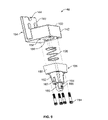
- FIG. 7 is an enlarged, perspective view of the static control device shown in FIG. 5 ;
- FIG. 8 is an enlarged, isolated side elevation view of the static control device shown in FIG. 7 ;
- FIG. 9 is an exploded, isolated view of the static control device shown in FIG. 7 ;
- FIG. 10 is a side elevation view of the reactivation system shown in FIG. 3 with the outer panels of enclosures surrounding the duct heaters of the reactivation system removed for clarity;
- FIG. 11 is a top plan view of the reactivation system shown in FIG. 10 ;
- FIG. 12 is an end view of the reactivation system of FIG. 10 .
- the term “explosion-proof” as it is used throughout the specification in connection with the dehumidification system described herein or any electrical component, element, part, module, or motor thereof, means that the enclosure thereof is capable of withstanding the pressure of an explosive mixture exploding inside the enclosure without rupture and capable of preventing the propagation of an explosion inside the enclosure to the atmosphere surrounding the enclosure.
- a dehumidification system designated generally with reference numeral 20 .
- the dehumidification system 20 is operable to remove moisture from air in an enclosed space (not shown).
- the dehumidification system 20 may be installed within the enclosed space or with appropriate modifications to ductwork, may be mounted externally of the enclosed space, either indoors or outdoors.
- the enclosed space may be located in a hazardous environment, for instance, a location classified as Class I, Zone 2, as defined in the 2002 edition of the Canadian Electrical Code, Part I, Section 18 entitled “Hazardous Locations” published by the Canadian Standards Association, Toronto Ontario; the disclosure of which is hereby incorporated by reference.
- flammable gas or vapour may be present in the air in quantities sufficient to produce an explosive or ignitable mixture.
- this hazard does not normally exist, it may occur under abnormal conditions.
- hazardous locations include off-shore drilling platforms, oil refineries, petrochemical plants, chemical production facilities and nuclear power plants.
- the dehumidification system 20 tends to be well-suited for safe deployment in such hazardous locations.
- the dehumidification system 20 is supported on a rectangular, box-like, rigid structural steel frame 22 constructed from a plurality of structural members in the nature of top and bottom longitudinal beams 24 , top and bottom transverse beams 26 , vertical posts 28 , and diagonal brace members 30 .
- the frame 22 includes a plurality of feet 32 —each foot 32 located at a respective corner 34 of the frame 22 —for placement on a structural support surface such as a roof or a floor. Spaced vertically from the feet 32 and extending between the longitudinal beams 24 of the frame 22 , is a pair of spaced-apart cross-members 36 upon which the dehumidification system 20 is mounted. As shown in FIGS.
- the frame 22 is open to thereby facilitate access to the dehumidification system 20 for routine maintenance or repairs.
- the frame could be constructed with outer panels or walls forming an enclosed structure for housing the dehumidification system 20 . Such an enclosed structure would provide enhanced environmental protection for the dehumidification system 20 .
- the dehumidification system 20 when supported on frame 22 , the dehumidification system 20 benefits from enhanced portability. It can be transported with ease to a work site for permanent or temporary deployment. For instance, in an exemplary application, the dehumidification system 20 can be deployed on a work site at a hazardous location where the resurfacing of metal surfaces is being undertaken. Humidity control on these work sites is of primary concern because the resurfacing activities involve blasting a metal surface to remove the old protective coating thereby exposing the underlying metal surface to the ambient air. If the level of humidity is left unchecked the exposed metal surface may be susceptible to corrosion before the new protective coating can be applied. Deployment of the dehumidification system 20 on the work site tends to substantially mitigate the risk of corrosion. Once the resurfacing activities have been completed in one area of the installation or facility, the dehumidification system 20 can be moved to the next worksite.
- the dehumidification system 20 includes: a desiccant wheel dehumidification assembly 38 having a desiccant wheel 40 with a process section 42 and a reactivation or regeneration section 44 and a static control device 46 associated with the desiccant wheel 40 to discourage the build-up of an electrostatic charge thereon; first blower means 48 for drawing a process air stream 50 from the enclosed space and urging it to flow through the process section 42 of the desiccant wheel 40 to thereby remove moisture from the process air stream 50 ; a process air outlet 52 located downstream of the process section 42 of the desiccant wheel 40 for exhausting the treated (dehumidified) process air stream 50 into the enclosed space; reactivation system 54 for heating a reactivation air stream 56 drawn from outside the enclosed space; second blower means 58 for drawing the reactivation air stream 56 from outside the enclosed space through the reactivation system 54 and urging it to flow through the reactivation section 44 of the des
- An electrical control system 62 governs actuation of the blower means 48 and 58 , the reactivation system 54 and the desiccant wheel assembly 38 .
- the control system 62 is housed in a generally square, protective enclosure 63 having a hinged lid 65 .
- the enclosure 63 is supported above the desiccant wheel assembly 38 by a pair of brackets 67 that extend between and depend from top longitudinal beam 24 .
- Both the control system 62 and the protective enclosure 63 are designed to be explosion-proof.
- the protective enclosure 63 and lid 65 are made of copper-free aluminum.
- the desiccant wheel dehumidification assembly 38 is housed in a box-like housing or cabinet 64 supported on cross-members 36 of frame 22 .
- the cabinet 64 is constructed from welded aluminum coated with durable, air-dry polyurethane paint.
- the cabinet 64 includes top and bottom walls 66 and 68 , front and rear, spaced, walls 70 and 72 , respectively, and a pair of opposed side walls 74 and 76 .
- the front wall 70 has a first cutout 80 to allow process air stream 50 to flow into the process section 42 of the desiccant wheel 40 from process air inlet 82 .
- a filter 84 mounted over process air inlet 82 , is a filter 84 for removing fairly large-sized airborne particles from the process air stream 50 prior to the process air stream 50 entering the process section 40 of the desiccant wheel. Operation of the filter 84 tends to prevent the particles from accumulating within the process section 42 and clogging same, and generally interfering with the proper functioning of the desiccant wheel 40 .
- the filter 84 is a metallic mesh filter; it is washable and it may be easily removed for cleaning.
- the front wall 70 has a second cutout 86 located above the first cutout 80 , adjacent the top wall 66 .
- the second cutout 86 permits reactivation air stream 56 to flow out from the reactivation section 44 of the desiccant wheel 40 and into the reactivation air outlet 60 for discharge into the atmosphere.
- Mounted over the reactivation air outlet 60 is a manually operable, damper assembly 87 including at least one rotatable louver 89 for selectively restricting air flow out of the reactivation outlet 60 .
- the second cutout 86 is connected to the reactivation air outlet 60 via ducting 88 .
- ducting 88 is capped by a square end plate 90 .
- a C-shaped structural channel member 92 is mounted to extend substantially perpendicular to end plate 90 in a generally cantilevered fashion, with one end thereof welded to the end plate 90 .
- the first blower means 48 is secured to, and supported by, the end plate 90 and the back of channel member 92 .
- the first blower means 48 includes a suction blower 94 driven by an electric motor (not shown).
- the electric motor is totally enclosed and designed to be explosion-proof.
- the motor driving suction blower 94 need not be an electric motor.
- pneumatically driven or hydraulically driven motors could be employed.
- Rear wall 72 includes first and second cutouts 96 and 98 , respectively.
- First cutout 96 is located adjacent the bottom wall 68 and allows process air stream 50 emerging from the process section 42 of the desiccant wheel 40 to flow into the process air outlet 52 for discharge into the enclosed space.
- a manually operable, damper assembly 99 identical to damper assembly 87 is mounted at the mouth of the process air outlet 52 and selectively restricts air flow into the enclosed space.
- the first cutout 96 is connected to the process air outlet 52 via ducting 100 .
- Ducting 100 is similar to ducting 88 described above.
- a square end plate 102 caps the distal end of ducting 100 .
- Mounted in cantilevered fashion to end plate 102 is a C-shaped structural channel member (not shown) similar to channel member 92 .
- the second blower means 58 is secured to, and supported by, the end plate 102 and the back of channel member 104 .
- Second blower means 58 is identical to first blower means 48 in that it includes a suction blower 103 driven by an electric motor (not shown) that it is designed to be explosion-proof.
- the second cutout 98 is located above first cutout 88 and is adapted to receive the stem portion 105 of Y-shaped, bifurcated conduit 106 (best shown in FIG. 3 ) that is connected to the reactivation system 54 .
- each of the side walls 74 and 76 has an outer access panel 107 which may be removed to permit easy access to the desiccant wheel assembly 38 for inspection or servicing without having to disconnect any ducting or electrical wiring.
- the outer access panels 107 may be provided with a small window (not shown) defined therein to allow visual inspection of the desiccant wheel assembly 38 .
- a pair of gauges 108 (only one of which can be seen in FIG. 5 ) is mounted within the cabinet 64 and visible from the side wall 74 .
- One gauge 108 displays air flow measurements relating to the process air stream 50 while the other displays air flow measurements relating to the reactivation air stream 56 .
- the desiccant wheel assembly 38 is mounted within the cabinet 64 between two interior walls 109 and 110 thereof.
- the desiccant wheel assembly 38 includes desiccant wheel 40 supported on a set of caster assemblies 111 (conceptually shown on FIG. 6 ).
- the caster assemblies 111 have bearing surfaces (not shown) upon which the desiccant wheel rests during rotation.
- An electric drive motor 112 is provided for driving rotation of the desiccant wheel 40 along its longitudinal axis. To mitigate the explosion hazard resulting from sparking of the brush contacts within the motor, the electric drive motor 112 is totally enclosed and designed to be explosion-proof.
- the electric drive motor may include an internal fan for cooling the motor.
- the electric drive motor may be outfitted with an air purging system that builds up a positive pressure of air to reduce the concentration of any flammable gas or vapour to an acceptable level within the motor such that explosive gases or vapours may be prevented from reaching electrical ignition sources. While in the preferred embodiment, an electric drive motor is used, it will be appreciated that in other embodiments pneumatically driven or hydraulically driven motors could be used to similar advantage.
- the electric drive motor 112 is operatively connected to the desiccant wheel 40 by way of a gear box 114 and a self-tensioning drive belt arrangement 116 that includes drive belt 118 .
- gear box 114 enables the delivered speed to be stepped down thereby allowing the desiccant wheel 40 to be rotatively driven at relatively low revolutions. In the preferred embodiment, the desiccant wheel 40 is driven to rotate at a rate of approximately 6 to 12 revolutions per hour.
- the electric drive motor 112 is connected to a junction box 119 that is designed to be explosion-proof.
- An electrical conduit system 120 comprising electrical lines (not shown) enclosed in sealed metal tubing 122 , is tied into the junction box 119 . The conduit system 120 serves to connect the electric drive motor 112 to the control system 62 .
- the desiccant wheel 40 includes an electrically conductive tubular body, casing or outer shell 124 and a monolithic, relatively lightweight, core 126 .
- the outer shell 124 is made of aluminum.
- other electrically conductive metals or alloys could also be used in the fabrication of the outer shell 124 .
- the core 126 has a matrix of honeycomb-like structures 128 made up of walls 130 .
- the walls 130 define generally uniform channels or passageways 132 extending substantially parallel to the axis of the air flow (process air stream 50 and reactivation air stream 56 ).
- the walls 130 are fabricated from a non-metallic, inorganic, non-corrosive, inert composite.
- the walls 130 are preferably made of extruded fiberglass paper fibers measuring at least 5 microns in diameter, and are impregnated with a solid, non-granular desiccant material in a known manner. The desiccant material is evenly dispersed throughout the core 126 .
- the following materials have been found to be suitable for use as a desiccant material in the desiccant wheel 40 : lithium chloride; silica gel, including titanium silica gel; and molecular sieve. Other materials that tend not to channel, cake or fracture due to repeated temperature and moisture cycling, may also be used as desiccant materials.
- the desiccant material When dry and cool, the desiccant material extracts moisture from air (sorption) because it has a low vapour pressure as compared to humid air. Conversely, the desiccant material releases moisture into the air (desorption) when it becomes wet and hot because under those conditions the desiccant material tends to have a high vapour pressure.
- the desiccant wheel 40 is considered to be an active desiccant wheel.
- the dehumidification system 20 uses heated reactivation air stream 56 within the reactivation section 44 of the desiccant wheel 40 to bring about release of the moisture from the desiccant material.
- the desiccant material will continuously alternate between high and low vapour pressures to alternately, adsorb moisture (from process air stream 50 ) and release moisture (into reactivation air stream 56 ).
- the dehumidification system 20 can continue to remove moisture from the process air stream 50 even when the dew point of the process air stream 50 is below freezing. It will thus be understood that, in contrast to conventional cooling-based dehumidification systems, the dehumidification system 20 tends to be very versatile and particularly well-suited for deployment in regions having cold climates.
- the desiccant wheel 40 employed is the HoneyCombe® Desiccant Wheel manufactured by Munters Corporation of Fort Myers, Fla., U.S.A.
- the remaining portion of the core 126 defines the process section 42 of the desiccant wheel 40 .
- the reactivation portion of the core 126 may occupy between about one quarter to one third of the surface area of the desiccant wheel 40 .
- the reactivation portion occupies one quarter of the surface area of the desiccant wheel 40 .
- the portions of the core 126 which define the process and reactivation sections 42 and 44 are constantly changing as a result of rotation of the desiccant wheel 40 . Accordingly, that the portion of the core 126 that is exposed to the process air stream 50 defines the process section 42 . Likewise, the portion of the core 126 that is exposed to the reactivation air stream 56 defines the reactivation section 44 .
- the process air stream 50 is drawn through the process section 42 toward the process air outlet 52 , simultaneously, within the reactivation section 44 , the reactivation air stream 56 is traveling in a direction opposite to that of process air stream 50 , toward the reactivation air outlet 60 .
- the desiccant wheel 40 accommodates two separate, counter-flowing or opposing air streams within its sections 42 and 44 .
- Contact pressure seals 131 mounted about the fore and aft rims of the outer shell 124 and the edges of partition member 133 are provided to separate the process air stream 50 from the reactivation air stream 56 and eliminate detrimental leakage of air or moisture within the cabinet 64 .
- the humidification system 20 is provided with static control device 46 .
- Static control device 46 provides a path to ground for continually draining static charges from the desiccant wheel. While in the preferred embodiment, the frame 22 serves as ground, it will be appreciated that in other embodiments, an alternative ground including an electrical ground could be employed.
- the static control device 46 includes a generally L-shaped, bracket 134 for attachment to the cabinet 64 , a mounting block assembly 136 depending from the bracket 134 and a grounding member 138 carried on the mounting block assembly 136 .
- the bracket 134 includes a first leg 140 integrally joined to a second leg 142 .
- the first leg 140 has three oblong slots 144 for receiving fasteners 146 therethrough. Fasteners 146 securely anchor the first leg 140 to the interior wall 109 of the cabinet 64 .
- the provision of slots 144 in the first leg 140 tends to facilitate adjustment of the position of the static control device 46 relative to the cabinet 64 and the desiccant wheel 40 .
- the second leg 142 has a proximal portion 148 connected to the first leg 140 , and terminates in a raised distal portion 150 which when seen in top plan view is generally square-shaped. At each corner thereof, the raised distal portion 150 has an aperture 152 that is adapted to receive a fastener 154 . The fastener 154 secures the second leg 142 to the mounting block assembly 136 .
- the distal portion 150 has a blind bore 156 formed on the underside thereof that is sized to accommodate a spring member 158 of mounting block assembly 136 .
- the mounting block assembly 136 has a hollow base 160 that is integrally formed with a frusto-conical portion 162 .
- the portion 162 has a bore (not shown) sized to receive therethrough the spring member 158 and a generally tubular member 163 .
- the tubular member 163 has a pair of spaced apart arms 164 for supporting the grounding member 138 .
- the grounding member 138 takes the form of a wheel or disc 165 .
- the disc 165 is rotatively mounted on an axle 166 extending between the arms 164 of the tubular member 163 .
- Frusto-conical portion 162 is provided with a transverse rebate 167 extending from its tip partway down to provide sufficient clearance to allow the disc 165 to protrude therethrough.
- Spring member 158 urges the tubular member 163 to bear against the inside of the frusto-conical portion 162 .
- the spring member is slightly compressed such that the disc 165 is biased against the outer shell 124 of the desiccant wheel 40 .
- Spring-loading the disc 165 in this manner ensures that the disc 165 maintains continuous contact with the outer shell of thereby reducing the instances of static charge build-up in the desiccant wheel.
- the bracket 134 could be modified to accommodate a tension adjustment mechanism to permit selective adjustment of the biasing of the disc 165 against the outer shell 124 .
- bracket member 134 and the mounting block assembly 136 are made of aluminum, while the grounding member 138 is made of steel.
- other electrically conductive metals or alloys could be used to fabricate the bracket member, mounting block assembly and grounding member.
- the grounding member 138 could be configured differently.
- the grounding member could include a brush member with metallic bristles for engaging one of the outer shell of the desiccant wheel, and one of the walls of the cabinet.
- the static control device 46 is mounted to the interior wall 109 , such that its position remains fixed relative to cabinet 64 . It will be appreciated that the static control device could also be mounted to one of the other walls of the cabinet, for instance, top wall 66 , bottom wall 68 , or one of side walls 76 or 78 .
- the static control device could be mounted onto the outer surface of outer shell 124 for rotation about the axis of rotation of the desiccant wheel 40 .
- the position of the static control device relative to the cabinet 64 would vary continuously.
- the alternative static control device would preferably be provided with biasing means to allow the grounding member to maintain constant or at least frequent contact with the cabinet in order to ensure proper grounding of the desiccant wheel assembly.
- the static control device could be designed for location at the fore and aft rims of the outer shell 124 .
- a set of ball bearings or the like fabricated from an electrically conductive metal or alloy, could be disposed between the fore rim of outer shell 124 and the interior wall 109 of the cabinet 64 , and between the aft rim and the interior wall 110 of cabinet 64 .
- the ball bearings would serve as the grounding member.
- the static control device could be positioned underneath the desiccant wheel.
- the static control device could include a brush member mounted to the bottom wall 68 of the desiccant wheel cabinet 64 with its bristles extending generally upwardly toward the outer shell 124 .
- the bristles of the brush could serve as the grounding member.
- the bristles could brush against the outer shell thereby continually draining static charges from the desiccant wheel.
- such a brush member could be mounted to one of the other walls of the cabinet.
- the static control device could be incorporated into the caster assemblies supporting the desiccant wheel 40 .
- at least a portion of the caster assemblies would define the static guard device.
- each caster assembly could be fabricated from an electrically conductive metal or alloy and connected to a ground.
- the grounding member could be an electrically conductive plate or flap hingedly mounted to one of the walls of the desiccant wheel cabinet, for instance, the bottom wall 66 .
- the flap could be biased against the outer shell 124 of the desiccant wheel 40 by way of a spring member or the like. It will thus be appreciated that the static control device may take various forms.
- desiccant wheel assembly 38 that includes a desiccant wheel 40 supported on caster assemblies 111 and mounted between two interior walls 109 and 110 of the desiccant wheel cabinet 64 .
- desiccant wheel assemblies there are alternate configurations of desiccant wheel assemblies that may be used in the dehumidification system. These desiccant wheel assemblies may require use of other static control devices.
- an alternate desiccant wheel assembly may have a desiccant wheel axially mounted about a central shaft, and a hub and bearing assembly.
- the desiccant wheel includes a core containing desiccant material surrounded by an electrically conductive outer shell.
- the desiccant wheel is driven to rotate about the shaft.
- the static control device could take the form of a rod, plate, or the like extending from the outer shell to the shaft.
- the shaft or the bearing assemblies would be connected to the ground.
- the reactivation system 54 includes a pair of generally rectangular duct assemblies 170 and 172 and a corresponding pair of air heating modules in the nature of duct heaters 174 and 176 .
- the duct assemblies 170 and 172 are supported by a structural bracket 178 extending from the frame 22 .
- Each duct assembly 170 , 172 includes a top wall 180 , a bottom wall 182 and a pair of opposed side walls 184 and 186 which co-operate together to define an interior passage 188 through which the reactivation air stream 56 will be urged to flow.
- the top wall 180 includes a cutout 190 to permit a portion of the duct heater 174 , 176 (as the case may be) to extend within the passage 188 .
- Each duct assembly 170 , 172 also has first and second ends 192 and 194 , respectively.
- Each end 192 , 194 has a flange 196 with a plurality of apertures to facilitate mounting of the duct assemblies.
- end 192 is connected to the branch 198 , 200 (as the case may be) of the bifurcated conduit 106 .
- a filter (not shown) similar to filter 84 described above, is mounted to the end 194 of the ducting assembly 170 , 172 .
- the duct assemblies 170 and 172 are constructed from carbon steel and coated with a rust-resistant, grey epoxy paint on its outer surfaces, and a high-temperature aluminum on its interior surfaces.
- duct heaters 174 and 176 are electrical heaters and are designed to be explosion-proof.
- Duct heater 174 is generally similar to duct heater 176 such that with minor modifications, the description of the former shall suffice for the latter.
- duct heater 174 has a plurality of spaced-apart heating elements 202 supported by a mounting plate 204 .
- the mounting plate 204 is adapted to fit over the cutout 190 defined in top wall 180 of duct assembly 170 , and is securely fastened to top wall 180 .
- the heating elements 202 extend downwardly from the mounting plate 204 into the interior passage 188 of duct assembly 170 .
- a plurality of pairs 206 of compression fittings 208 corresponding to the plurality of heating elements 202 stand proud of the mounting plate 204 .
- Each compression fitting 208 of a respective pair 206 receives therethrough an end of a respective heating element 202 for electrical connection to a terminal block assembly (not shown) housed within a terminal enclosure 210 located above the duct assembly 170 .
- each heating element 202 includes a heavy walled carbon steel tubular sheath 212 with nickel plated finish on which is brazed a plurality of fins 214 .
- the compression fittings 208 are preferably fabricated from nickel plated brass and are designed to be explosion-proof.
- the terminal enclosure 210 has a generally tubular body fabricated from extruded copper-free aluminum. It is designed to be explosion-proof. In the preferred embodiment, the terminal enclosure used is manufactured by CCI Thermal Technologies Inc. of Edmonton, Alberta, Canada, and is described more fully in U.S. Pat. No. 5,798,910 issued to Holbeche et al., the disclosure of which is hereby incorporated herein. When the dehumidification system 20 is deployed on a work site, the terminal enclosure 210 is protected from the environment with a housing 216 .
- Actuation of the duct heaters 174 and 176 is governed by the control system 62 .
- the control system 62 will be selectively actuate the other duct heater to maintain the reactivation air stream 56 exiting the reactivation air outlet 60 at a predetermined temperature. In the preferred embodiment, this temperature is 50° C.
- first and second reactivation electrical conduit systems 218 and 220 extends between the terminal enclosures 208 of duct heaters 174 and 176 .
- First electrical conduit system 218 connects the respective terminal block assemblies of duct heaters 174 and 176 to each other, while the second electrical conduit system 220 connects their respective thermocouple terminal blocks.
- a third reactivation electrical conduit system 222 extending from the control system 62 is connected to the first electrical conduit system 218 .
- Electrical conduits 218 , 220 and 222 are generally similar to electrical conduit system 120 described above.
- Each duct heater 174 , 176 is further provided with temperature control means that includes at least one thermocouple 224 , and an explosion-proof differential pressure switch 224 (best shown in FIG. 10 ).
- Thermocouple 224 extends from one of the heating elements 202 , through the top plate 180 , and into the terminal enclosure 210 for connection to a thermocouple terminal block (not shown).
- Differential pressure switch 226 is supported on an elongate bracket 228 that is fixedly attached to a plate 230 .
- the plate 230 in turn is mounted to side wall 184 , 186 (as the case may be).
- the pressure switch 226 of each duct heater is operatively connected to the other and to the control system 62 by way of an electrical conduit system 232 generally similar to electrical conduit system 120 described above.
- All electrical conduits 120 , 218 , 220 , 222 and 232 and all other wiring in the dehumidification system 20 are appropriate for use in hazardous environments.
- reactivation system 54 uses electrical energy to heat the reactivation air stream 54 (by way of electrically powered duct heaters 174 and 176 ), this need not be the case in every application. It will be understood that in alternative embodiments, electrical reactivation could be replaced with steam reactivation or gas fired (direct or indirect) reactivation to similar advantage. Heat generated from steam or gas could be used to heat the reactivation air stream.
- the desiccant wheel 40 When the dehumidification system 20 is deployed, the desiccant wheel 40 is driven to rotate and both suction blowers 94 are 103 actuated. Suction blower 94 draws moist process air stream 50 from the enclosed space through the process air inlet 82 defined in the desiccant wheel cabinet 64 .
- the process air stream 50 flows through filter 84 and ducting 88 and into the process air section 42 of the desiccant wheel 40 .
- the process air stream 50 As it passes through the process section 42 , the process air stream 50 is stripped of its moisture by the desiccant material impregnated within the walls 130 of desiccant wheel core 126 .
- the treated (dried) process air stream 50 is then evacuated through the process air outlet 52 and returned to the enclosed space.
- suction blower 105 draws reactivation air stream 56 from the atmosphere outside the enclosed space into the duct assemblies 170 and 172 .
- the flow rate of reactivation air stream 56 through duct assemblies 170 and 172 is maintained at, at least 15.6 m 3 /min.
- the reactivation air stream 56 moves through the interior passages 188 its temperature increases as a result of heat transfer between the heating elements 202 of duct heaters 174 and 176 and the reactivation air stream 56 .
- the temperature of the reactivation air stream 56 reaches between about 137° C. and 160° C.
- the thus heated reactivation air stream 56 flows through the bifurcated conduit 106 and into the reactivation section 44 of the desiccant wheel 40 , where it serves to regenerate the portion of the desiccant wheel core 126 that was exposed to the moist process air stream 50 earlier.
- the reactivation air stream 50 heats the walls 130 of the desiccant wheel core 126 , thereby causing the desiccant material to release the moisture into the reactivation air stream 50 .
- the now moist reactivation air stream 56 leaves the cabinet 64 and is then evacuated through the reactivation air outlet 60 into the atmosphere outside the enclosed space.
- the desiccant material Prior to re-entering the process section 42 , the desiccant material is cooled in order to further reduce the vapour pressure of the desiccant material and enhance its moisture adsorbing properties.
- the slow rotation speed of the desiccant wheel 40 tends to promote cooling of the desiccant material.
Abstract
Description
Claims (50)
Priority Applications (1)
| Application Number | Priority Date | Filing Date | Title |
|---|---|---|---|
| US11/226,269 US7308798B2 (en) | 2005-09-15 | 2005-09-15 | Dehumidification system |
Applications Claiming Priority (1)
| Application Number | Priority Date | Filing Date | Title |
|---|---|---|---|
| US11/226,269 US7308798B2 (en) | 2005-09-15 | 2005-09-15 | Dehumidification system |
Publications (2)
| Publication Number | Publication Date |
|---|---|
| US20070056307A1 US20070056307A1 (en) | 2007-03-15 |
| US7308798B2 true US7308798B2 (en) | 2007-12-18 |
Family
ID=37853677
Family Applications (1)
| Application Number | Title | Priority Date | Filing Date |
|---|---|---|---|
| US11/226,269 Active 2026-05-12 US7308798B2 (en) | 2005-09-15 | 2005-09-15 | Dehumidification system |
Country Status (1)
| Country | Link |
|---|---|
| US (1) | US7308798B2 (en) |
Cited By (12)
| Publication number | Priority date | Publication date | Assignee | Title |
|---|---|---|---|---|
| US20080279721A1 (en) * | 2007-03-06 | 2008-11-13 | Weiss Richard A | Decontamination unit and process |
| US20100084483A1 (en) * | 2006-12-29 | 2010-04-08 | Carrier Corporation | System and Method for Controlling Temperature and Humidity of a Controlled Space |
| US20110011260A1 (en) * | 2009-06-08 | 2011-01-20 | Mario Caggiano | Microwave reactivation system for standard and explosion-proof dehumidification system |
| US7900372B2 (en) * | 2008-04-18 | 2011-03-08 | Mabe Canada Inc. | Clothes dryer with louvre cover |
| US20110056220A1 (en) * | 2009-06-08 | 2011-03-10 | Mario Caggiano | PH2OCP - portable water and climatic production system |
| US7905097B1 (en) * | 2009-10-05 | 2011-03-15 | Hamilton Sundstrand Corporation | Water-from-air system using a desiccant wheel |
| US20110296858A1 (en) * | 2010-06-02 | 2011-12-08 | 7291345 Canada Inc. | Ph2ocp portable water and climatic production system |
| US20120055183A1 (en) * | 2009-04-22 | 2012-03-08 | Airbus S.A.S. | System and method for cooling a space in a vehicle |
| EP2630413A1 (en) * | 2010-06-02 | 2013-08-28 | 7734123 Canada Inc | Microwave reactivation system for standard and explosion-proof dehumidification |
| US8852328B2 (en) | 2010-12-16 | 2014-10-07 | Prometheus Technologies, Llc | Rotary fluid processing systems and associated methods |
| US8943848B2 (en) | 2010-06-16 | 2015-02-03 | Reznor Llc | Integrated ventilation unit |
| CN104441318A (en) * | 2014-12-16 | 2015-03-25 | 江苏宏远新材料科技有限公司 | Honeycomb runner device of dehumidifier |
Families Citing this family (12)
| Publication number | Priority date | Publication date | Assignee | Title |
|---|---|---|---|---|
| US9668385B2 (en) | 2010-12-22 | 2017-05-30 | Cooper Technologies Company | Controlling airflow within an explosion-proof enclosure |
| CA2819890C (en) | 2010-12-22 | 2019-01-15 | Cooper Technologies Company | Manifold for controlling airflow within an explosion-proof enclosure |
| US8247097B1 (en) * | 2011-06-10 | 2012-08-21 | Tesla Motors, Inc. | Method of controlling battery pack humidity utilizing an active reactivation system |
| GB2502157B (en) * | 2012-05-19 | 2018-11-07 | Redring Xpelair Group Ltd | Rotating Heat Exchanger |
| US9506752B2 (en) * | 2014-11-05 | 2016-11-29 | Finetek Co., Ltd. | Explosion-proof dust of electromechanical level measuring device |
| SE543515C2 (en) | 2019-03-19 | 2021-03-16 | Munters Europe Ab | A method and a particle protection device for a dehumidifier |
| SE2150531A1 (en) | 2021-04-27 | 2022-10-28 | Munters Europe Ab | An air treatment element, an air treatment unit and a method for producing the air treatment element |
| US11123678B2 (en) * | 2021-05-04 | 2021-09-21 | GPL Odorizers LLC | Air filtration device |
| SE545070C2 (en) | 2021-08-23 | 2023-03-21 | Munters Europe Ab | Gas sorption system |
| SE545313C2 (en) | 2021-08-23 | 2023-06-27 | Munters Europe Ab | A desiccant dehumidifier |
| CN113824004B (en) * | 2021-11-22 | 2022-03-04 | 四川蜀电成套设备有限公司 | Energy-saving and environment-friendly switch cabinet |
| SE2250840A1 (en) | 2022-07-04 | 2024-01-05 | Munters Europe Ab | A system and method for controlling humidity in a defined space |
Citations (12)
| Publication number | Priority date | Publication date | Assignee | Title |
|---|---|---|---|---|
| US3844737A (en) * | 1970-03-31 | 1974-10-29 | Gas Dev Corp | Desiccant system for an open cycle air-conditioning system |
| US4134743A (en) * | 1970-03-31 | 1979-01-16 | Gas Developments Corporation | Desiccant apparatus and method |
| US4948392A (en) * | 1989-07-25 | 1990-08-14 | Institute Of Gas Technology | Heat input for thermal regenerative desiccant systems |
| WO1996041107A1 (en) * | 1995-06-07 | 1996-12-19 | Engelhard/Icc | Dessicant assisted dehumidification and cooling system |
| US5659974A (en) * | 1995-05-04 | 1997-08-26 | Graeff; Roderich Wilhelm | Method for regeneration of an adsorbent material containing moisture and apparatus therefor |
| US5667560A (en) * | 1993-10-25 | 1997-09-16 | Uop | Process and apparatus for dehumidification and VOC odor remediation |
| US6029462A (en) * | 1997-09-09 | 2000-02-29 | Denniston; James G. T. | Desiccant air conditioning for a motorized vehicle |
| US20020142208A1 (en) * | 2000-10-30 | 2002-10-03 | Keefer Bowie G. | Energy efficient gas separation for fuel cells |
| US20030143448A1 (en) * | 2000-10-30 | 2003-07-31 | Questair Technologies Inc. | High temperature fuel cell power plant |
| US6767391B2 (en) * | 2001-07-10 | 2004-07-27 | Nichias Co., Ltd. | Air filter |
| US6918263B2 (en) * | 2002-12-26 | 2005-07-19 | Lg Electronics Inc. | Air conditioning system |
| US7166149B2 (en) * | 2004-01-12 | 2007-01-23 | Uop Llc | Adsorption process for continuous purification of high value gas feeds |
-
2005
- 2005-09-15 US US11/226,269 patent/US7308798B2/en active Active
Patent Citations (13)
| Publication number | Priority date | Publication date | Assignee | Title |
|---|---|---|---|---|
| US3844737A (en) * | 1970-03-31 | 1974-10-29 | Gas Dev Corp | Desiccant system for an open cycle air-conditioning system |
| US4134743A (en) * | 1970-03-31 | 1979-01-16 | Gas Developments Corporation | Desiccant apparatus and method |
| US4948392A (en) * | 1989-07-25 | 1990-08-14 | Institute Of Gas Technology | Heat input for thermal regenerative desiccant systems |
| US5667560A (en) * | 1993-10-25 | 1997-09-16 | Uop | Process and apparatus for dehumidification and VOC odor remediation |
| US5659974A (en) * | 1995-05-04 | 1997-08-26 | Graeff; Roderich Wilhelm | Method for regeneration of an adsorbent material containing moisture and apparatus therefor |
| WO1996041107A1 (en) * | 1995-06-07 | 1996-12-19 | Engelhard/Icc | Dessicant assisted dehumidification and cooling system |
| US6029462A (en) * | 1997-09-09 | 2000-02-29 | Denniston; James G. T. | Desiccant air conditioning for a motorized vehicle |
| US20020142208A1 (en) * | 2000-10-30 | 2002-10-03 | Keefer Bowie G. | Energy efficient gas separation for fuel cells |
| US20030143448A1 (en) * | 2000-10-30 | 2003-07-31 | Questair Technologies Inc. | High temperature fuel cell power plant |
| US7097925B2 (en) * | 2000-10-30 | 2006-08-29 | Questair Technologies Inc. | High temperature fuel cell power plant |
| US6767391B2 (en) * | 2001-07-10 | 2004-07-27 | Nichias Co., Ltd. | Air filter |
| US6918263B2 (en) * | 2002-12-26 | 2005-07-19 | Lg Electronics Inc. | Air conditioning system |
| US7166149B2 (en) * | 2004-01-12 | 2007-01-23 | Uop Llc | Adsorption process for continuous purification of high value gas feeds |
Cited By (26)
| Publication number | Priority date | Publication date | Assignee | Title |
|---|---|---|---|---|
| US20100084483A1 (en) * | 2006-12-29 | 2010-04-08 | Carrier Corporation | System and Method for Controlling Temperature and Humidity of a Controlled Space |
| US8393549B2 (en) * | 2006-12-29 | 2013-03-12 | Carrier Corporation | System and method for controlling temperature and humidity of a controlled space |
| US8153078B2 (en) | 2007-03-06 | 2012-04-10 | Steris Inc. | Transportable decontamination unit and decontamination process |
| US20080279722A1 (en) * | 2007-03-06 | 2008-11-13 | Bacik Michael A | Transportable decontamination unit and decontamination process |
| US20080279721A1 (en) * | 2007-03-06 | 2008-11-13 | Weiss Richard A | Decontamination unit and process |
| US8216523B2 (en) | 2007-03-06 | 2012-07-10 | Steris Inc. | Decontamination unit with collapsible decontamination enclosure and decontamination process |
| US8182743B1 (en) | 2007-03-06 | 2012-05-22 | Steris Inc. | Transportable decontamination unit and decontamination process |
| US7993601B2 (en) | 2007-03-06 | 2011-08-09 | Steris Inc. | Decontamination unit and process |
| US8163236B1 (en) | 2007-03-06 | 2012-04-24 | Steris Inc. | Transportable decontamination unit and decontamination process |
| US8128888B2 (en) | 2007-03-06 | 2012-03-06 | Steris Inc. | Transportable decontamination unit and decontamination process |
| US7900372B2 (en) * | 2008-04-18 | 2011-03-08 | Mabe Canada Inc. | Clothes dryer with louvre cover |
| US20120055183A1 (en) * | 2009-04-22 | 2012-03-08 | Airbus S.A.S. | System and method for cooling a space in a vehicle |
| US8545609B2 (en) * | 2009-06-08 | 2013-10-01 | 7142871 Canada Inc. | Microwave reactivation system for standard and explosion-proof dehumidification system |
| US8551230B2 (en) * | 2009-06-08 | 2013-10-08 | 7142871 Canada Inc. | PH2OCP—portable water and climatic production system |
| US20110011260A1 (en) * | 2009-06-08 | 2011-01-20 | Mario Caggiano | Microwave reactivation system for standard and explosion-proof dehumidification system |
| US20110056220A1 (en) * | 2009-06-08 | 2011-03-10 | Mario Caggiano | PH2OCP - portable water and climatic production system |
| US7905097B1 (en) * | 2009-10-05 | 2011-03-15 | Hamilton Sundstrand Corporation | Water-from-air system using a desiccant wheel |
| US20110079028A1 (en) * | 2009-10-05 | 2011-04-07 | Hamilton Sundstrand Corporation | Water-from-air system using a desiccant wheel |
| EP2630413A1 (en) * | 2010-06-02 | 2013-08-28 | 7734123 Canada Inc | Microwave reactivation system for standard and explosion-proof dehumidification |
| US20110296858A1 (en) * | 2010-06-02 | 2011-12-08 | 7291345 Canada Inc. | Ph2ocp portable water and climatic production system |
| EP2630413A4 (en) * | 2010-06-02 | 2015-04-29 | 7142871 Canada Inc | Microwave reactivation system for standard and explosion-proof dehumidification |
| US8943848B2 (en) | 2010-06-16 | 2015-02-03 | Reznor Llc | Integrated ventilation unit |
| US9816724B2 (en) | 2010-06-16 | 2017-11-14 | Reznor Llc | Integrated ventilation unit |
| US8852328B2 (en) | 2010-12-16 | 2014-10-07 | Prometheus Technologies, Llc | Rotary fluid processing systems and associated methods |
| US9302215B2 (en) | 2010-12-16 | 2016-04-05 | Prometheus Technologies, Llc | Rotary fluid processing systems and associated methods |
| CN104441318A (en) * | 2014-12-16 | 2015-03-25 | 江苏宏远新材料科技有限公司 | Honeycomb runner device of dehumidifier |
Also Published As
| Publication number | Publication date |
|---|---|
| US20070056307A1 (en) | 2007-03-15 |
Similar Documents
| Publication | Publication Date | Title |
|---|---|---|
| US7308798B2 (en) | Dehumidification system | |
| US8545609B2 (en) | Microwave reactivation system for standard and explosion-proof dehumidification system | |
| EP2714585B1 (en) | Ph20cp-portable water and climatic production system | |
| US8551230B2 (en) | PH2OCP—portable water and climatic production system | |
| US7338548B2 (en) | Dessicant dehumidifer for drying moist environments | |
| US4450900A (en) | Mobile air conditioning unit | |
| US5817167A (en) | Desiccant based dehumidifier | |
| US7284387B2 (en) | Diesel fuel heated dessicant reactivation with internal heat bypass | |
| CA3007596C (en) | Desiccant wheel for a portable dehumidifier | |
| CA2835570C (en) | Microwave reactivation system for standard and explosion-proof dehumidification | |
| US20060064891A1 (en) | Diesel fuel heated dessicant reactivation with pre-dry reactivation air | |
| US7284386B2 (en) | Self-contained trailer for diesel fuel heated dessicant reactivation | |
| US10401053B2 (en) | Fan bracket for a portable dehumidifier | |
| US8361206B2 (en) | Generator heat recovery for diesel fuel heated dessicant reactivation | |
| US7284383B2 (en) | Wheel belt drive for diesel fuel heated dessicant reactivation | |
| US20060059923A1 (en) | 2-Line residential use diesel fuel heated dessicant reactivator | |
| CA2835366C (en) | Ph2ocp-portable water and climatic production system | |
| EP0979379A1 (en) | Air treatment device, installation, and method | |
| US20090078114A1 (en) | System and method for recovering ice-clad machinery and equipment | |
| KR100688391B1 (en) | System for processing total-hydrocarbon by catalyst oxidation | |
| EP1528333B1 (en) | Air dehumidifier and dehumidification method | |
| Kong et al. | Assessment of styrene emission controls for FRP/C and boat building industries | |
| Tykesson et al. | The benefits of dry air preservation power plants | |
| JPH0562717B2 (en) | ||
| AU2003259656A1 (en) | Dehumidifying Air |
Legal Events
| Date | Code | Title | Description |
|---|---|---|---|
| AS | Assignment |
Owner name: MUNTERS INC. (50% RIGHTS), CANADA Free format text: ASSIGNMENT OF ASSIGNORS INTEREST;ASSIGNOR:BERNARDO, FABIO;REEL/FRAME:018126/0084 Effective date: 20060725 |
|
| STCF | Information on status: patent grant |
Free format text: PATENTED CASE |
|
| AS | Assignment |
Owner name: # 7142871 CANADA INC., CANADA Free format text: INTELLECTUAL PROPERTY SALE AGREEMENT;ASSIGNOR:CAGGIANO, MARIO, MR.;REEL/FRAME:022824/0707 Effective date: 20090515 |
|
| AS | Assignment |
Owner name: MAXIMOFF ADVANCED ENGINEERED SYSTEMS & TECHNOLOGIE Free format text: ASSIGNMENT OF ASSIGNORS INTEREST;ASSIGNOR:7142871 CANADA INC.;REEL/FRAME:025699/0238 Effective date: 20101223 |
|
| FPAY | Fee payment |
Year of fee payment: 4 |
|
| AS | Assignment |
Owner name: MUNTERS INC., CANADA Free format text: INTELLECTUAL PROPERTY AGREEMENT;ASSIGNORS:CAGGIANO, MARIO;MUNTERS INC.;REEL/FRAME:026610/0399 Effective date: 20060424 Owner name: CAGGIANO, MARIO, CANADA Free format text: INTELLECTUAL PROPERTY AGREEMENT;ASSIGNORS:CAGGIANO, MARIO;MUNTERS INC.;REEL/FRAME:026610/0399 Effective date: 20060424 |
|
| AS | Assignment |
Owner name: DRYCO GROUP EXPLOSION PROOF EQUIPMENT, LLC, ILLINO Free format text: COURT ORDER (JUDGE WHITE, CIR. CT. COOK CTY., IL);ASSIGNOR:MAXIMOFF ADVANCED ENGINEERED SYSTEMS & TECHNOLOGIES INC.;REEL/FRAME:030037/0360 Effective date: 20121205 Owner name: DRYCO GROUP EXPLOSION PROOF EQUIPMENT, LLC, ILLINO Free format text: COURT ORDER (JUDGE WHITE, CIR, CT, COOK CTY., IL);ASSIGNOR:MAXIMOFF ADVANCED ENGINEERED SYSTEMS & TECHNOLOGIES INC.;REEL/FRAME:030009/0896 Effective date: 20121205 |
|
| AS | Assignment |
Owner name: DRYCO GROUP EXPLOSION PROOF EQUIPMENT, LLC, ILLINO Free format text: CORRECTIVE ASSIGNMENT TO CORRECT THE PATENT NUMBER FROM 7308398 TO 7308798 PREVIOUSLY RECORDED ON REEL 030629 FRAME 0177. ASSIGNOR(S) HEREBY CONFIRMS THE COURT ORDER (JUDGE WHITE, CIR.CT.COOK CTY.);ASSIGNOR:MAXIMOFF ADVANCED ENGINEERED SYSTEMS & TECHNOLOGIES, INC.;REEL/FRAME:033358/0935 Effective date: 20130617 |
|
| FPAY | Fee payment |
Year of fee payment: 8 |
|
| AS | Assignment |
Owner name: JOE SCHROEDER, INC., ILLINOIS Free format text: MERGER;ASSIGNOR:DRYCO GROUP EXPLOSION PROOF EQUIPMENT, LLC;REEL/FRAME:039655/0939 Effective date: 20160531 |
|
| AS | Assignment |
Owner name: AGGREKO, LLC, TEXAS Free format text: ASSIGNMENT OF ASSIGNORS INTEREST;ASSIGNOR:JOE SCHROEDER, INC.;REEL/FRAME:039801/0800 Effective date: 20160808 |
|
| FEPP | Fee payment procedure |
Free format text: ENTITY STATUS SET TO UNDISCOUNTED (ORIGINAL EVENT CODE: BIG.); ENTITY STATUS OF PATENT OWNER: LARGE ENTITY |
|
| MAFP | Maintenance fee payment |
Free format text: PAYMENT OF MAINTENANCE FEE, 12TH YEAR, LARGE ENTITY (ORIGINAL EVENT CODE: M1553); ENTITY STATUS OF PATENT OWNER: LARGE ENTITY Year of fee payment: 12 |
|
| AS | Assignment |
Owner name: GLAS TRUST CORPORATION LIMITED, UNITED KINGDOM Free format text: SECURITY AGREEMENT SUPPLEMENT;ASSIGNOR:AGGREKO, LLC;REEL/FRAME:058845/0260 Effective date: 20211022 |