EP4028252B1 - Vorrichtung, system und verfahren zum nachhärten eines gegenstandes - Google Patents
Vorrichtung, system und verfahren zum nachhärten eines gegenstandes Download PDFInfo
- Publication number
- EP4028252B1 EP4028252B1 EP20771627.5A EP20771627A EP4028252B1 EP 4028252 B1 EP4028252 B1 EP 4028252B1 EP 20771627 A EP20771627 A EP 20771627A EP 4028252 B1 EP4028252 B1 EP 4028252B1
- Authority
- EP
- European Patent Office
- Prior art keywords
- chamber
- light
- article
- leds
- initiation
- Prior art date
- Legal status (The legal status is an assumption and is not a legal conclusion. Google has not performed a legal analysis and makes no representation as to the accuracy of the status listed.)
- Active
Links
Images


Classifications
-
- A—HUMAN NECESSITIES
- A61—MEDICAL OR VETERINARY SCIENCE; HYGIENE
- A61C—DENTISTRY; APPARATUS OR METHODS FOR ORAL OR DENTAL HYGIENE
- A61C13/00—Dental prostheses; Making same
- A61C13/0003—Making bridge-work, inlays, implants or the like
- A61C13/0004—Computer-assisted sizing or machining of dental prostheses
-
- A—HUMAN NECESSITIES
- A61—MEDICAL OR VETERINARY SCIENCE; HYGIENE
- A61C—DENTISTRY; APPARATUS OR METHODS FOR ORAL OR DENTAL HYGIENE
- A61C19/00—Dental auxiliary appliances
- A61C19/003—Apparatus for curing resins by radiation
-
- B—PERFORMING OPERATIONS; TRANSPORTING
- B29—WORKING OF PLASTICS; WORKING OF SUBSTANCES IN A PLASTIC STATE IN GENERAL
- B29C—SHAPING OR JOINING OF PLASTICS; SHAPING OF MATERIAL IN A PLASTIC STATE, NOT OTHERWISE PROVIDED FOR; AFTER-TREATMENT OF THE SHAPED PRODUCTS, e.g. REPAIRING
- B29C64/00—Additive manufacturing, i.e. manufacturing of three-dimensional [3D] objects by additive deposition, additive agglomeration or additive layering, e.g. by 3D printing, stereolithography or selective laser sintering
- B29C64/10—Processes of additive manufacturing
- B29C64/106—Processes of additive manufacturing using only liquids or viscous materials, e.g. depositing a continuous bead of viscous material
- B29C64/124—Processes of additive manufacturing using only liquids or viscous materials, e.g. depositing a continuous bead of viscous material using layers of liquid which are selectively solidified
- B29C64/129—Processes of additive manufacturing using only liquids or viscous materials, e.g. depositing a continuous bead of viscous material using layers of liquid which are selectively solidified characterised by the energy source therefor, e.g. by global irradiation combined with a mask
- B29C64/135—Processes of additive manufacturing using only liquids or viscous materials, e.g. depositing a continuous bead of viscous material using layers of liquid which are selectively solidified characterised by the energy source therefor, e.g. by global irradiation combined with a mask the energy source being concentrated, e.g. scanning lasers or focused light sources
-
- B—PERFORMING OPERATIONS; TRANSPORTING
- B29—WORKING OF PLASTICS; WORKING OF SUBSTANCES IN A PLASTIC STATE IN GENERAL
- B29C—SHAPING OR JOINING OF PLASTICS; SHAPING OF MATERIAL IN A PLASTIC STATE, NOT OTHERWISE PROVIDED FOR; AFTER-TREATMENT OF THE SHAPED PRODUCTS, e.g. REPAIRING
- B29C71/00—After-treatment of articles without altering their shape; Apparatus therefor
- B29C71/04—After-treatment of articles without altering their shape; Apparatus therefor by wave energy or particle radiation, e.g. for curing or vulcanising preformed articles
-
- A—HUMAN NECESSITIES
- A61—MEDICAL OR VETERINARY SCIENCE; HYGIENE
- A61C—DENTISTRY; APPARATUS OR METHODS FOR ORAL OR DENTAL HYGIENE
- A61C13/00—Dental prostheses; Making same
- A61C13/0003—Making bridge-work, inlays, implants or the like
- A61C13/0006—Production methods
- A61C13/0019—Production methods using three dimensional printing
-
- B—PERFORMING OPERATIONS; TRANSPORTING
- B29—WORKING OF PLASTICS; WORKING OF SUBSTANCES IN A PLASTIC STATE IN GENERAL
- B29C—SHAPING OR JOINING OF PLASTICS; SHAPING OF MATERIAL IN A PLASTIC STATE, NOT OTHERWISE PROVIDED FOR; AFTER-TREATMENT OF THE SHAPED PRODUCTS, e.g. REPAIRING
- B29C35/00—Heating, cooling or curing, e.g. crosslinking or vulcanising; Apparatus therefor
- B29C35/02—Heating or curing, e.g. crosslinking or vulcanizing during moulding, e.g. in a mould
- B29C35/08—Heating or curing, e.g. crosslinking or vulcanizing during moulding, e.g. in a mould by wave energy or particle radiation
- B29C35/0805—Heating or curing, e.g. crosslinking or vulcanizing during moulding, e.g. in a mould by wave energy or particle radiation using electromagnetic radiation
- B29C2035/0827—Heating or curing, e.g. crosslinking or vulcanizing during moulding, e.g. in a mould by wave energy or particle radiation using electromagnetic radiation using UV radiation
-
- B—PERFORMING OPERATIONS; TRANSPORTING
- B29—WORKING OF PLASTICS; WORKING OF SUBSTANCES IN A PLASTIC STATE IN GENERAL
- B29C—SHAPING OR JOINING OF PLASTICS; SHAPING OF MATERIAL IN A PLASTIC STATE, NOT OTHERWISE PROVIDED FOR; AFTER-TREATMENT OF THE SHAPED PRODUCTS, e.g. REPAIRING
- B29C35/00—Heating, cooling or curing, e.g. crosslinking or vulcanising; Apparatus therefor
- B29C35/02—Heating or curing, e.g. crosslinking or vulcanizing during moulding, e.g. in a mould
- B29C35/08—Heating or curing, e.g. crosslinking or vulcanizing during moulding, e.g. in a mould by wave energy or particle radiation
- B29C35/0805—Heating or curing, e.g. crosslinking or vulcanizing during moulding, e.g. in a mould by wave energy or particle radiation using electromagnetic radiation
- B29C2035/0833—Heating or curing, e.g. crosslinking or vulcanizing during moulding, e.g. in a mould by wave energy or particle radiation using electromagnetic radiation using actinic light
-
- B—PERFORMING OPERATIONS; TRANSPORTING
- B29—WORKING OF PLASTICS; WORKING OF SUBSTANCES IN A PLASTIC STATE IN GENERAL
- B29C—SHAPING OR JOINING OF PLASTICS; SHAPING OF MATERIAL IN A PLASTIC STATE, NOT OTHERWISE PROVIDED FOR; AFTER-TREATMENT OF THE SHAPED PRODUCTS, e.g. REPAIRING
- B29C2791/00—Shaping characteristics in general
- B29C2791/004—Shaping under special conditions
- B29C2791/006—Using vacuum
-
- B—PERFORMING OPERATIONS; TRANSPORTING
- B29—WORKING OF PLASTICS; WORKING OF SUBSTANCES IN A PLASTIC STATE IN GENERAL
- B29C—SHAPING OR JOINING OF PLASTICS; SHAPING OF MATERIAL IN A PLASTIC STATE, NOT OTHERWISE PROVIDED FOR; AFTER-TREATMENT OF THE SHAPED PRODUCTS, e.g. REPAIRING
- B29C64/00—Additive manufacturing, i.e. manufacturing of three-dimensional [3D] objects by additive deposition, additive agglomeration or additive layering, e.g. by 3D printing, stereolithography or selective laser sintering
- B29C64/10—Processes of additive manufacturing
- B29C64/106—Processes of additive manufacturing using only liquids or viscous materials, e.g. depositing a continuous bead of viscous material
- B29C64/124—Processes of additive manufacturing using only liquids or viscous materials, e.g. depositing a continuous bead of viscous material using layers of liquid which are selectively solidified
-
- B—PERFORMING OPERATIONS; TRANSPORTING
- B29—WORKING OF PLASTICS; WORKING OF SUBSTANCES IN A PLASTIC STATE IN GENERAL
- B29L—INDEXING SCHEME ASSOCIATED WITH SUBCLASS B29C, RELATING TO PARTICULAR ARTICLES
- B29L2031/00—Other particular articles
- B29L2031/753—Medical equipment; Accessories therefor
- B29L2031/7532—Artificial members, protheses
- B29L2031/7536—Artificial teeth
-
- B—PERFORMING OPERATIONS; TRANSPORTING
- B33—ADDITIVE MANUFACTURING TECHNOLOGY
- B33Y—ADDITIVE MANUFACTURING, i.e. MANUFACTURING OF THREE-DIMENSIONAL [3-D] OBJECTS BY ADDITIVE DEPOSITION, ADDITIVE AGGLOMERATION OR ADDITIVE LAYERING, e.g. BY 3-D PRINTING, STEREOLITHOGRAPHY OR SELECTIVE LASER SINTERING
- B33Y40/00—Auxiliary operations or equipment, e.g. for material handling
- B33Y40/20—Post-treatment, e.g. curing, coating or polishing
-
- B—PERFORMING OPERATIONS; TRANSPORTING
- B33—ADDITIVE MANUFACTURING TECHNOLOGY
- B33Y—ADDITIVE MANUFACTURING, i.e. MANUFACTURING OF THREE-DIMENSIONAL [3-D] OBJECTS BY ADDITIVE DEPOSITION, ADDITIVE AGGLOMERATION OR ADDITIVE LAYERING, e.g. BY 3-D PRINTING, STEREOLITHOGRAPHY OR SELECTIVE LASER SINTERING
- B33Y70/00—Materials specially adapted for additive manufacturing
- B33Y70/10—Composites of different types of material, e.g. mixtures of ceramics and polymers or mixtures of metals and biomaterials
-
- B—PERFORMING OPERATIONS; TRANSPORTING
- B33—ADDITIVE MANUFACTURING TECHNOLOGY
- B33Y—ADDITIVE MANUFACTURING, i.e. MANUFACTURING OF THREE-DIMENSIONAL [3-D] OBJECTS BY ADDITIVE DEPOSITION, ADDITIVE AGGLOMERATION OR ADDITIVE LAYERING, e.g. BY 3-D PRINTING, STEREOLITHOGRAPHY OR SELECTIVE LASER SINTERING
- B33Y80/00—Products made by additive manufacturing
Definitions
- the present disclosure broadly relates to devices for post-curing articles, methods, and, post-cured articles.
- EP 3378435 A1 discloses a method for polymerizing or cross-linking a dental composition that includes a photosensitive material
- WO 92/04171 A1 discloses method and an apparatus for use in the curing of fusible materials which after being filled into a mould are cured by means of radiation
- US 2018/0141243 A1 discloses a method of post-curing a modeled object in a green state based on modeling data generated according to a working model includes a curing step of exposing the modeled object to light while the modeled object is fitted to the working model to secondary-cure the modeled object.
- an apparatus in a first aspect, includes a) a housing; b) a chamber disposed in the housing; c) at least two light emitting diodes (LEDs) disposed within the housing; and a user interface disposed on an exterior of the housing.
- the chamber is configured to be adaptable to each of an open configuration, a closed configuration, and a hermetically sealed configuration, and the chamber includes a material transparent to actinic radiation. Light from the at least two LEDs enters the chamber from more than one direction.
- the user interface includes a display and a plurality of program switches configured to adjust at least three operational parameters of the apparatus.
- the at least three operational parameters comprise 1) light intensity provided by the at least two LEDs, 2) length of time of light provided by the at least two LEDs, and at least one of 3a) delay time between initiation of light provided by the at least two LEDs and initiation of vacuum pulled on an interior of the chamber by the vacuum pump or 3b) delay time between initiation of vacuum pulled on an interior of the chamber by the vacuum pump and initiation of light provided by the at least two LEDs.
- the apparatus further includes a vacuum pump operatively connected to the chamber.
- An article includes a plurality of layers of at least one photopolymerized crosslinked composition. Further, the article contains 0.1% by weight or less of extractable components, based on the total weight of the article, when extracted with 5 volume percent ethanol in water.
- the article is made by a process including a) obtaining a photopolymerizable composition; b) selectively curing the photopolymerizable composition using actinic radiation to form an article having a plurality of layers of at least one photopolymerized composition; c) removing excess photopolymerizable composition from the article; d) placing the article in the apparatus of the first aspect; e) inputting a post-cure program or accessing a saved post-cure program through the user interface; and f) running the post-cure program.
- the post-cure program includes i) light intensity provided by the at least two LEDs, ii) length of time of light provided by the at least two LEDs, and at least one of iiia) delay time between initiation of light provided by the at least two LEDs and initiation of vacuum pulled by the vacuum pump or iiib) delay time between initiation of vacuum pulled on an interior of the chamber by the vacuum pump and initiation of light provided by the at least two LEDs.
- a method of post-curing an article includes a) obtaining an article; b) placing the article in an apparatus; c) inputting a post-cure program or accessing a saved post-cure program through the user interface; and d) running the post-cure program.
- the apparatus includes 1) a housing; 2) a chamber disposed in the housing; 3) at least one light source comprising two light emitting diodes (LEDs) disposed within the housing; 4) a user interface disposed on an exterior of the housing, the user interface comprising a display and a plurality of program switches configured to adjust at least three operational parameters of the apparatus; and 5) a vacuum pump operatively connected to the chamber.
- the post-cure program includes i) light intensity provided by the at least one light source, ii) length of time of light provided by the at least one light source, and at least one of iiia) delay time between initiation of light provided by the at least one light source and initiation of vacuum pulled by the vacuum pump or iiib) delay time between initiation of vacuum pulled on an interior of the chamber by the vacuum pump and initiation of light provided by the at least one light source.
- An article may be made by the method of the second aspect.
- a system in a third aspect, includes a) an apparatus of the first aspect; and b) an article including at least one photopolymerized composition.
- apparatuses of the present disclosure can provide greater user control than previous devices.
- methods of using the apparatuses and articles post-cured according to at least certain embodiments of this disclosure were found to provide articles having a low extractables content, e.g., as compared to instead using other post-curing methods.
- the term "essentially free" in the context of a composition being essentially free of a component refers to a composition containing less than 1% by weight (wt.%), 0.5 wt.% or less, 0.25 wt.% or less, 0.1 wt.% or less, 0.05 wt.% or less, 0.001 wt.% or less, or 0.0001 wt.% or less of the component, based on the total weight of the composition.
- polymeric refers to containing at least one polymer.
- the term "cavity” refers to an empty space, which is defined by at least one wall of a (e.g., solid) object.
- curing means the hardening or partial hardening of a composition by any mechanism, e.g., by heat, light, radiation, e-beam, microwave, chemical reaction, or combinations thereof.
- hardenable refers to a material that can be cured or solidified, e.g., by heating to remove solvent, heating to cause polymerization, chemical crosslinking, radiation-induced polymerization or crosslinking, or the like.
- cured refers to a material or composition that has been hardened or partially hardened (e.g., polymerized or crosslinked) by curing.
- transparent refers to a material that has a thickness of 10 millimeters or less and has at least 50% transmittance, 70% transmittance, or optionally greater than 90% transmittance over a particular range of wavelengths.
- the term "generally”, unless otherwise specifically defined, means that the property or attribute would be readily recognizable by a person of ordinary skill but without requiring absolute precision or a perfect match (e.g., within +/- 20 % for quantifiable properties).
- the term “substantially”, unless otherwise specifically defined, means to a high degree of approximation (e.g., within +/- 10% for quantifiable properties) but again without requiring absolute precision or a perfect match. Terms such as same, equal, uniform, constant, strictly, and the like, are understood to be within the usual tolerances or measuring error applicable to the particular circumstance rather than requiring absolute precision or a perfect match.
- the present disclosure provides an apparatus.
- the apparatus comprises:
- Apparatuses according to at least certain embodiments of the present disclosure advantageously provide increased user control over operation of the apparatuses.
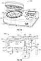
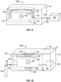
- an apparatus 1000 comprises a housing 110 and a chamber 120 disposed in the housing 110.
- the housing 110 is typically formed of polymeric material, metal, and/or glass.
- the chamber 120 is configured to be adaptable to each of an open configuration ( FIG. 1A , in which a hinged lid 122 is raised to allow access to the interior of the chamber 120), a closed configuration ( FIG. 1B , in which the hinged lid 122 is shut), and a hermetically sealed configuration ( FIG. 1C , in which the hinged lid 122 is shut and atmosphere cannot leave or enter the chamber due to the presence of a flexible sealing element 123 that can be seen in FIG. 1A ).
- a flexible sealing element 123 assists in the capability of adjusting the pressure inside of the chamber 120 and maintaining a selected pressure (e.g., using a vacuum pump 150) within the chamber 120 when the hinged lid 122 is closed.
- a flexible sealing element is a rubber o-ring.
- the chamber 120 comprises a material transparent to actinic radiation.
- the chamber may comprise a material that is transparent to actinic radiation having wavelengths of at least 250 nanometers (nm), 300 nm or greater, 350 nm or greater, 400 nm or greater, 450 nm or greater, 500 nm or greater, 550 nm or greater, or 600 nm or greater; and 900 nm or less, 850 nm or less, 800 nm or less, 750 nm or less, 700 nm or less, or 650 nm or less.
- material of which at least a portion of the chamber is made is transparent to actinic radiation between 250 nm and 900 nm or between 250 and 650 nm.
- Suitable materials of which at least a portion of the chamber is made that are transparent to actinic radiation include glass and quartz.
- the chamber 120 comprises at least two, at least three, or at least four glass walls through which actinic radiation enters the chamber.
- the chamber 120 comprises at least two, at least three, or at least four quartz walls through which actinic radiation enters the chamber. Combinations of glass and quartz can be included in the same chamber, if desired.
- the chamber 120 is cylindrical and has one curved side wall.
- At least two light emitting diodes (LEDs) 130 are disposed within the housing 110, such that light from the at least two LEDs 130 enters the chamber 120 from more than one direction.
- a first LED is positioned to direct light through a first major surface of the chamber 121 and a second LED is positioned to direct light through an opposing second major surface of the chamber 123.
- a floor of the chamber is the first major surface of the chamber and a lid of the chamber 122 is the second major surface of the chamber.
- the apparatus 1000 further comprises a third LED positioned to direct light through a third major surface 125 of the chamber, wherein the third major surface 125 is directly adjacent to each of the first major surface of the chamber 121 and the second major surface of the chamber 123.
- the apparatus 1000 further comprises a fourth LED positioned to direct light through a fourth major surface of the chamber 127, wherein the fourth major surface 127 is opposite the third major surface of the chamber 125.
- a first LED encompasses the presence of more than one LED located at the position of the first LED, e.g., an array of individual LED bulbs may be provided as each of the first LED, the second LED, etc., rather than “a first LED” being limited to a single LED bulb.
- each of the LEDs provide light having a peak wavelength between 250 nm and 500 nm.
- at least two LEDs are present that provide light having a peak wavelength below 360 nm, above 460 nm, or both.
- the (e.g., at least two) LEDs provide a light intensity of 50 milliwatts per square centimeter (mW/cm 2 ), or greater, 100 mW/cm 2 or greater, 150 mW/cm 2 or greater, 200 mW/cm 2 or greater, 250 mW/cm 2 or greater, or 300 mW/cm 2 or greater; and 500 mW/cm 2 or less, 450 mW/cm 2 or less, 400 mW/cm 2 or less, or 350 mW/cm 2 or less.
- the LEDs may provide a light intensity of 50 to 500 mW/cm 2 or 300 to 500 mW/cm 2 .
- the apparatus 1000 further comprises a diffusing element 135 disposed between at least one LED 130 and the chamber 120.
- a diffusing element is an optical element or a collection of elements having light transmission of at least 50%.
- Diffusing elements can be volume diffusers such as diffuser plates, or foams. They can also be surface diffusers, diffractive or holographic diffusers, bead coated substrates, or surface structure on substrates.
- An exemplary surface diffuser is available, for example, as an optical ground glass diffuser from Edmund Optics Inc., Barrington, USA.
- the apparatus may include a diffusing element positioned to diffuse light provided from any one or more of the light sources; e.g., an apparatus having four light sources may include one, two, three, or four separate diffusing elements.
- the apparatus 1000 further comprises a reflective material 132 positioned in the housing 110 to reflect actinic radiation through a first major surface of the chamber 121 or an opposing second major surface of the chamber 123.
- Suitable reflective materials include for instance and without limitation, metals such as aluminum or silver.
- the reflective material is optionally a layer that is either self-supporting or is a coating layer on a substrate (e.g., a polymeric and/or a glass substrate).
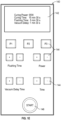
- the apparatus 1000 further comprises a user interface 140 disposed on an exterior 112 of the housing.
- the user interface 140 comprises a display 142 and a plurality of program switches 144 configured to adjust at least three operational parameters of the apparatus.
- the apparatus 1000 comprises a vacuum pump 150 operatively connected to the (e.g., curing) chamber 120, for instance using tubing 152 connected to the vacuum pump 150 and to the chamber 120, placing the two in fluid communication with each other.
- operatively connected refers to two structures and/or devices that are attached (either directly or indirectly) such that each structure and/or device is capable of functioning with the other.
- a vacuum pump may be operatively connected to a chamber using tubing, wherein the vacuum pump lowers the pressure in the chamber by pulling a vacuum through the tubing between the vacuum pump and the chamber to evacuate gas from the chamber.
- the vacuum pump is configured to achieve an absolute pressure inside the chamber of 0.1 millibars (mbar) or greater, 0.25 mbar or greater, 0.5 mbar or greater, 0.75 mbar or greater, 1 mbar or greater, 2 mbar or greater, 3 mbar or greater, 4 mbar or greater, or 5 mbar or greater; and 30 mbar or less, 27 mbar or less, 25 mbar or less, 23 mbar or less, 20 mbar or less, 17 mbar or less, 15 mbar or less, 12 mbar or less, or 10 mbar or less.
- mbar millibars
- the vacuum pump can be configured to achieve an absolute pressure inside the chamber of 0.1 to 30 mbar, 5 to 20 mbar, or 0.1 to 10 mbar.
- the extent of vacuum within the chamber can vary according to the particular application.
- the vacuum pump 150 is located on the exterior of the housing 110, and an optional three-way valve 154 is shown that connects the chamber 120 to the vacuum pump 150 and/or to a gas source 160.
- the three-way valve 154 also connects to tubing 162 that is connected to the gas source 160.
- Other typical connectors such as fittings or valves could optionally be used in conjunction with the vacuum pump 150.
- FIG. 1B the vacuum pump 150 is located on the exterior of the housing 110, and an optional three-way valve 154 is shown that connects the chamber 120 to the vacuum pump 150 and/or to a gas source 160.
- Other typical connectors such as fittings or valves could optionally be used in conjunction with the vacuum pump 150.
- the vacuum pump 150 is located within the housing 110 and a first valve 156 and a second valve 166 are each operatively connected to the chamber 120 (e.g., via tubing 152 and 162, respectively).
- the first valve 156 operatively connects the chamber 120 to the vacuum pump 150 and the second valve 166 operatively connects the chamber 120 to the gas source 160.
- Suitable gas sources include, for example, a container (e.g., pressurized gas cylinder) holding compressed gas, e.g., an inert gas.
- Typical inert gases for use with the apparatus include nitrogen, argon, and/or helium.
- an exemplary apparatus 1000 is shown in which an optional release valve 155 operatively connects the chamber 120 to an exterior of the housing 110, such as through tubing 157.
- the release valve provides a conduit through which pressure can be equalized between the interior of the chamber and ambient pressure outside of the apparatus. This is advantageous for being able to open the lid of the chamber following use of a vacuum or a gas within the chamber.
- the chamber 120 is formed of material(s) capable of maintaining its structural integrity at a range of internal pressures.
- a chamber comprises a toughened safety glass with a compressive strength of 700-900 N/mm.
- the glass thickness can be calculated according to DIN standard 7080:2005-05 "Pressure resistant circular sight glasses of borosilicate glass without limitation in the range of low temperature".
- the glass thickness needed for a particular chamber is dependent on the size of the chamber being formed.
- One suitable glass thickness is approximately 5 millimeters.
- the user interface 140 has a display 142 and numerous program switches 144 comprising at least one button, at least one dial (e.g., in FIG. 1B ), or a combination thereof.
- the embodiment shown in FIG. 1E includes eleven buttons 144. Any number of buttons 144 (or dials) can be dedicated to either raising or lowering selected values of parameters such as gas flushing time, light intensity (e.g., power), vacuum delay time, and/or time of light emission.
- the user interface comprises a start button 146, which may be configured (e.g., electronically coupled to the LEDs) such that pressing the start button initiates light emitted by the LEDs.
- the start button 146 is configured (e.g., electronically coupled to the program switches 144) to initiate a program that has been entered via the user interface.
- the user interface 140 comprises a touch screen 143 that provides the display and the plurality of program switches (e.g., in FIG. 1C ).
- the display 142 is not a touch screen.
- the program switches 144 are further configured to adjust a time of flushing the chamber 120 with a gas from the gas source 160, pressure of flushing the chamber 120 with the gas, or both.
- the apparatus 1000 further comprises a processor 170.
- the processor 170 causes the (e.g., at least two) LEDs 130 to emit light and the vacuum pump 150 to operate according to a program inputted through the user interface 140. Any suitable computer processor could be incorporated into the apparatus.
- the processor 170 further comprises a memory 172, which provides the capability of causing the LEDs 130 to emit light and/or the vacuum pump 150 to operate according to a program that is stored in the memory 172.
- the processor 170 is electronically coupled to the user interface 140, either wirelessly or physically via electrical connections.
- operational parameters of the apparatus that are adjustable by the user interface comprise 1) light intensity provided by the LEDs, 2) length of time of light provided by the LEDs, and 3) delay time between initiation of light provided by the LEDs and initiation of vacuum pulled on an interior of the chamber by the vacuum pump.
- operational parameters of the apparatus that are adjustable by the user interface comprise 1) light intensity provided by the LEDs, 2) length of time of light provided by the LEDs, and 3) delay time between initiation of vacuum pulled on an interior of the chamber by the vacuum pump and initiation of light provided by the LEDs.
- Suitable lengths of time for light to be provided by the LEDs comprise 1 minute or greater, 2 minutes or greater, 3 minutes or greater, 4 minutes or greater, 5 minutes or greater, 6 minutes or greater, 7 minutes or greater, 8 minutes or greater, 9 minutes or greater, 10 minutes or greater, 11 minutes or greater, 13 minutes or greater, 15 minutes or greater, 16 minutes or greater, 18 minutes or greater, or 20 minutes or greater; and 180 minutes or less, 150 minutes or less, 125 minutes or less, 100 minutes or less, 80 minutes or less, 60 minutes or less, 40 minutes or less, 30 minutes or less, 25 minutes or less, or 21 minutes or less, 18 minutes or less, 16 minutes or less, or 12 minutes or less, such as 7 minutes to 25 minutes.
- Suitable times between initiation of light provided by the LEDs and initiation of vacuum pulled on an interior of the chamber by the vacuum pump comprise 5 seconds or greater, 7 seconds or greater, 10 seconds or greater, 12 seconds or greater, 15 seconds or greater, 25 seconds or greater, 30 seconds or greater, 40 seconds or greater, 50 seconds or greater, 60 seconds or greater, or 70 seconds or greater; and 15 minutes or less, 13 minutes or less, 11 minutes or less, 9 minutes or less, 7 minutes or less, 5 minutes or less, 3 minutes or less, 2 minutes or less, or 1 minute or less, such as 10 seconds to 3 minutes.
- Suitable times between initiation of vacuum pulled on an interior of the chamber by the vacuum pump and initiation of light provided by the LEDs comprise 5 seconds or greater, 7 seconds or greater, 10 seconds or greater, 12 seconds or greater, 15 seconds or greater, 25 seconds or greater, 30 seconds or greater, 40 seconds or greater, 50 seconds or greater, 60 seconds or greater, or 70 seconds or greater; and 5 minutes or less, 4.5 minutes or less, 4 minutes or less, 3.5 minutes or less, 3 minutes or less, 2.5 minutes or less, 2 minutes or less, 1.5 minutes or less, 1 minute or less, 50 seconds or less, 40 seconds or less, or 30 seconds or less, such as 5 seconds to 40 seconds.
- An article comprises a plurality of layers of at least one photopolymerized crosslinked composition, the article comprising 0.1% by weight or less of extractable components, based on the total weight of the article, when extracted with 5 volume percent ethanol in water, the article made by a process comprising:
- the article may be made by a process including obtaining a photopolymerizable composition 410; selectively curing the photopolymerizable composition using actinic radiation to form an article comprising a plurality of layers of at least one photopolymerized composition 420; and removing excess photopolymerizable composition from the article 430.
- the article is placed in an apparatus (e.g., as described above in detail with respect to the first aspect) 440, followed by inputting a post-cure program or accessing a saved post-cure program through the user interface 450 and running the post-cure program 460.
- the post-cure program comprises 1) light intensity provided by at least two light sources (e.g., LEDs); 2) length of time of light provided by at least two light sources; and at least one of 3a) delay time between initiation of light provided by the light sources and initiation of vacuum pulled by the vacuum pump or 3b) delay time between initiation of vacuum pulled on an interior of the chamber by the vacuum pump and initiation of light provided by the light sources.
- Suitable light intensities and times are as described above with respect to the apparatuses.
- the post-cure program comprises turning on a first light source for a predetermined amount of time, followed by turning on a second light source for a predetermined amount of time, wherein the amounts of time may be the same or different.
- the first light source and the second light source can be employed for either some or no overlapping time.
- the first light source may provide a different light wavelength (or range of wavelengths) and/or intensity than the second light source.
- the post-cure program is inputted through the user interface shortly before running that post-cure program.
- the post-cure program is saved in a memory of a processor, either due to being pre-installed by the apparatus manufacturer or entered and saved by a user.
- a user can activate (e.g., press and hold a program switch such as any one of P1, P2, or P3 buttons 144 shown in FIG. 1E ) for up to several seconds for the inputted program to be saved to that program switch.
- a user may simply select the program by activating a program switch (e.g., pressing a button, turning a dial, touching a touch sensor display in a certain place, etc.) to which the program is saved.
- a program switch e.g., pressing a button, turning a dial, touching a touch sensor display in a certain place, etc.
- the article contains 0.1% by weight or less of extractable components, based on the total weight of the article, when extracted with 5 volume percent ethanol in water, 0.9% by weight or less, 0.8% by weight or less, 0.7% by weight or less, 0.6% by weight or less, 0.5% by weight or less, or 0.4% by weight or less of extractable components; and 0.01% by weight or more, 0.03% by weight or more, 0.05% by weight or more, 0.07% by weight or more, or 0.1% by weight or more of extractable components, based on the total weight of the article, when extracted with 5 volume percent ethanol in water.
- a suitable test procedure for determining the amount of extractable components includes placing an article having a total surface area of 45 cm 2 in a 40 milliliter (mL) glass vial and weighing the vial. 15 mL of solvent (5 volume % ethanol/Milli-Q water) is added to the vial, with one 15 mL blank (vial containing solvent but without articles). The vials are covered with TEFLON caps and the samples are kept at 37 °C for 24 hours while shaking at 80 revolutions per minute (RPM) in a shaker (e.g., a LabLine Benchtop incubated shaker, Model No. 4628). The samples are allowed to cool before transferring the extraction solution to a new 20 mL glass vial.
- RPM revolutions per minute
- % Residue vial after evaporation g ⁇ vial tare g ⁇ 15 mL solvent mass of article g ⁇ 5 mL solvent analyzed ⁇ 100
- compositions are suitable for use in the methods according to the present disclosure.
- the compositions include at least one polymerizable component.
- component encompasses compounds, monomers, oligomers, and polymers.
- a "polymerizable component,” for reference purposes herein, comprises a hardenable component that can be cured to provide a printed article.
- hardening comprises irradiating with actinic radiation having sufficient energy to initiate a polymerization or cross-linking reaction.
- actinic radiation having sufficient energy to initiate a polymerization or cross-linking reaction.
- UV radiation ultraviolet
- e-beam radiation e-beam radiation, or both, can be used.
- the photopolymerizable composition includes at least one of a (meth)acryl component, an epoxy component, a polyalkylene component, a polyalkylene oxide component, a polyester component, a polycarbonate component, a urethane component, a polyamide component, a thiol component and an ene component that is different from the (meth)acryl component, or combinations thereof.
- a photopolymerizable composition includes a (meth)acryl component in combination with one or more of an epoxy component, a polyalkylene component, a polyalkylene oxide component, a polyester component, a polycarbonate component, a urethane component, and/or a polyamide component.
- Suitable photopolymerizable compositions include for instance and without limitation, the compositions described in detail in the following published applications: WO 2020/104873 (Klun et al. ); WO 2020/003169 (Wu et al. ), WO 2020/003197 (Klun et al. ), WO 2020/005413 (Klun et al. ), and WO 2019/175716 (Abuelyaman et al. ); and published applications WO 2019/103855 (Parkar et al. )), WO 2019/023009 (Parkar et al. )), WO 2019/104072 (Chakraborty et al.
- Suitable articles that may be made using photopolymerizable compositions include for instance and without limitation, dental articles, such as to crowns, bridges, veneers, inlays, onlays, fillings, and prostheses (e.g., partial or full dentures); and orthodontic appliances and devices such as orthodontic brackets, buccal tubes, lingual retainers, orthodontic bands, class II and class III correctors, sleep apnea devices, bite openers, buttons, cleats, and other attachment devices.
- the article is an orthodontic article or a dental restoration.
- the photopolymerized composition comprises a (meth)acryl polymer and at least one ceramic material, a urethane (meth)acryl polymer, a polyalkylene oxide (meth)acryl polymer, a polyalkylene oxide urethane (meth)acryl polymer, a polyester urethane (meth)acryl polymer, a polycarbonate urethane (meth)acryl polymer, a polyamide polymer, an epoxy (meth)acrylate polymer, a thioether polymer, or any combination thereof.
- the photopolymerized composition comprises a (meth)acryl polymer and at least one ceramic material.
- photopolymerized composition comprises a polycarbonate urethane (meth)acryl polymer.
- (meth)acrylate is a shorthand reference to acrylate, methacrylate, or combinations thereof
- (meth)acrylic is a shorthand reference to acrylic, methacrylic, or combinations thereof
- (meth)acryl is a shorthand reference to acryl and methacryl groups.
- Acryl refers to derivatives of acrylic acid, such as acrylates, methacrylates, acrylamides, and methacrylamides.
- (meth)acryl is meant a monomer or oligomer having at least one acryl or methacryl groups, and linked by an aliphatic segment if containing two or more groups.
- (meth)acrylate-functional compounds are compounds that include, among other things, a (meth)acrylate moiety.
- the photopolymerizable composition contains ceramic particles as a ceramic material.
- ceramic particle includes particles of amorphous material, glass, crystalline ceramic, glass-ceramic, and combinations thereof, and refers to non-metallic materials produced by application of heat or made by a chemical synthesis process. Ceramic particles are usually classified as inorganic materials.
- amorphous material with respect to ceramic particles refers to a material derived from a melt and/or a vapor phase as well as a material made from chemical synthesis, wherein the material lacks long range crystal structure as determined by X-ray diffraction and/or has an exothermic peak corresponding to the crystallization of the amorphous material as determined by DTA (differential thermal analysis).
- DTA differential thermal analysis
- amorphous silica nanoparticles may be generated by condensation of silanes to form the nanoparticles.
- the optional ceramic particles comprise metal oxide ceramic particles, non-oxide ceramic particles, or any combination thereof.
- the ceramic particles are selected from the group consisting of zirconia (ZrO 2 ), silica (SiO 2 ), alumina (Al 2 O 3 ), yttria (Y 2 O 3 ), ceria (CeO 2 ), magnesium-magnesia aluminate (MMA), magnesium oxide (MgO), hydroxyapatite (Cas(PO 4 ) 3 OH), fluorapatite (Ca 5 (PO 4 ) 3 F), chlorapatite (Cas(PO 4 ) 3 Cl), calcite (CaCO 3 ), cordierite (Mg 2 Al 4 Si 5 O 18 ), silicon carbide (SiC), silicon nitride (Si 3 N 4 ), boron carbide (B 4 C), titanium diboride (TiB 2 ), zirconium diboride (ZrB 2 ), boron nitride (BN), titanium carbide (TiC), zirconium carbide (ZrC), zir
- high-purity particles are used, in which the total content of metal impurities is preferably less than 100 ppm, particularly preferably less than 50 ppm. In alternate embodiments, particles are used having a total content of metal impurities of about 2,000 ppm. Suitable ceramic particles are described in detail in published Application WO 2021/024162 .
- the photopolymerizable composition which may be a slurry or sol, comprises 20 wt.% or greater ceramic particles, based on the total weight of the photopolymerizable composition, 21 wt.% or greater, 22 wt.%, 23 wt.%, 24 wt.%, 25 wt.%, 26 wt.%, 27 wt.%, 28 wt.%, 29 wt.%, 30 wt.%, 32 wt.% or 35 wt.% or greater; and 60 wt.% or less, 29.5 wt.% or less, 28.5 wt.% or less, 27.5 wt.% or less, 26.5 wt.% or less, 25.5 wt.% or less, or 24.5 wt.% or less ceramic particles, based on the total weight of the photopolymerizable composition.
- the photopolymerizable composition (e.g., slurry or sol) comprises 3 volume percent (vol.%) or greater ceramic particles, based on the total volume of the photopolymerizable composition, 4 vol.%, 5 vol.%, 6 vol.%, 7 vol.%, 8 vol.%, 9 vol.%, 10 vol.%, 11 vol.%, 12 vol.%, 13 vol.%, 14 vol.%, 15 vol.%, 17 vol.
- slurry refers to a continuous liquid phase containing discrete particles having sizes in a range from 1 nanometer (nm) to 100 nm.
- slurry refers to a continuous liquid phase containing discrete particles having sizes in a range from greater than 100 nm to 50 micrometers or from greater than 100 nm to 10 micrometers. A slurry may optionally further contain discrete particles having sizes in a range from 1 nanometer (nm) to 100 nm.
- a “particle” refers to a substance being a solid having a shape which can be geometrically determined. The shape can be regular or irregular. Particles can typically be analyzed with respect to e.g., particle size and particle size distribution.
- a particle can comprise one or more crystallites.
- a particle can comprise one or more crystal phases.
- the ceramic particles typically comprise an average (mean) particle size diameter (i.e., D 50 ) of 1 nanometer (nm) or greater, 3 nm, 4 nm, 5 nm, 6 nm, 7 nm, 8 nm, 9 nm, 10 nm, 12 nm, 15 nm, 17 nm, 20 nm, 25 nm, 30 nm, 40 nm, 50 nm, 60 nm, 75 nm, 90 nm, 100 nm, 125 nm, 150 nm, 175 nm, 200 nm, 225 nm, 250 nm, 350 nm, 500 nm, 750 nm, 1 micrometer, 1.25 micrometers, 1.5 micrometers, 1.75 micrometers, 2 micrometers, 2.5 micrometers, 3.0 micrometers, 3.5 micrometers, 4.0 micrometers, or 4.5 micrometers or greater; and a D 50 of 10 micrometers or less
- the average (mean) particle size (D 50 ) refers to that particle diameter at which 50 percent by volume of the particles in a distribution of particles have that diameter or a smaller diameter, as measured by scanning electron microscopy or transmission electron microscopy.
- the average particle size is of the primary particles.
- Photopolymerizable compositions of the present disclosure typically include at least one photoinitiator.
- Suitable exemplary photoinitiators are those available under the trade designations OMNIRAD from IGM Resins (Waalwijk, The Netherlands) and include 1-hydroxycyclohexyl phenyl ketone (OMNIRAD 184), 2,2-dimethoxy-1,2-diphenylethan-1-one (OMNIRAD 651), bis(2,4,6 trimethylbenzoyl)phenylphosphineoxide (OMNIRAD 819), 1-[4-(2-hydroxyethoxy)phenyl]-2-hydroxy-2-methyl-1-propane-1-one (OMNIRAD 2959), 2-benzyl-2-dimethylamino-1-(4-morpholinophenyl)butanone (OMNIRAD 369), 2-Dimethylamino-2-(4-methyl-benzyl)-1-(4-morpholin-4-yl-phenyl)- butan-1-one (OMNIRAD 379
- Suitable photoinitiators include for example and without limitation, benzyl dimethyl ketal, 2-methyl-2-hydroxypropiophenone, benzoin methyl ether, benzoin isopropyl ether, anisoin methyl ether, aromatic sulfonyl chlorides, photoactive oximes, and combinations thereof.
- a cationic photoinitiator is present in compositions that include epoxy component, for example.
- a thermal initiator can optionally be present in a photopolymerizable composition described herein. For instance, a free-radical photoinitiator, a cationic photoinitiator, a thermal photoinitiator, or any combination thereof may be present in a photopolymerizable composition.
- Suitable cationic photoinitiators include for instance and without limitation, bis[4-diphenylsulfoniumphenyl] sulfide bishexafluoroantimonate; thiophenoxyphenylsulfonium hexafluoroantimonate (available as CHIVACURE 1176 from Chitec (Houston, TX), tris(4-(4-acetylphenyl)thiophenyl)sulfonium tetrakis(pentafluorophenyl)borate, tris(4-(4-acetylphenyl)thiophenyl)sulfonium tris[(trifluoromethyl)sulfonyl]methide, and tris(4-(4-acetylphenyl)thiophenyl)sulfonium hexafluorophosphate, [4-(1-methylethyl)phenyl](4-methylphenyl) io
- a photoinitiator is present in a photopolymerizable composition in an amount of up to about 5% by weight, based on the total weight of polymerizable components in the photopolymerizable composition (e.g., not including components such as ceramic particles). In some cases, a photoinitiator is present in an amount of about 0.1-5% by weight, 0.2-5% by weight, or 0.5-5% by weight, based on the total weight of the photopolymerizable composition.
- a thermal initiator is present in a photopolymerizable composition or in an amount of up to about 5% by weight, based on the total weight of polymerizable components in the photopolymerizable composition. In some cases, a thermal initiator is present in an amount of about 0.1-5% by weight, based on the total weight of polymerizable components in the photopolymerizable composition.
- Suitable thermal initiators include for instance and without limitation, peroxides such as benzoyl peroxide, dibenzoyl peroxide, dilauryl peroxide, cyclohexane peroxide, methyl ethyl ketone peroxide, hydroperoxides, e.g., tert -butyl hydroperoxide and cumene hydroperoxide, dicyclohexyl peroxydicarbonate, 2,2,-azo-bis(isobutyronitrile), and t-butyl perbenzoate.
- peroxides such as benzoyl peroxide, dibenzoyl peroxide, dilauryl peroxide, cyclohexane peroxide, methyl ethyl ketone peroxide
- hydroperoxides e.g., tert -butyl hydroperoxide and cumene hydroperoxide
- dicyclohexyl peroxydicarbonate 2,2,-azo-
- thermal initiators examples include initiators available from DuPont Specialty Chemical (Wilmington, DE) under the VAZO trade designation including VAZO 67 (2,2'-azo-bis(2-methybutyronitrile)) VAZO 64 (2,2'-azo-bis(isobutyronitrile)) and VAZO 52 (2,2'-azo-bis(2,2-dimethyvaleronitrile)), and LUCIDOL 70 from Elf Atochem North America, Philadelphia, PA.
- VAZO 67 (2,2'-azo-bis(2-methybutyronitrile)
- VAZO 64 2,2'-azo-bis(isobutyronitrile)
- VAZO 52 2,2'-azo-bis(2,2-dimethyvaleronitrile)
- LUCIDOL 70 from Elf Atochem North America, Philadelphia, PA.
- the composition contains a first free-radical photoinitiator having sufficient absorbance at a first wavelength range; and a second free-radical initiator selected from a second photoinitiator having sufficient absorbance at a second wavelength range, wherein the second wavelength range is different than the first wavelength range, or a thermal free-radical initiator.
- first free-radical photoinitiators include for instance and without limitation, acyl phosphine oxide and alkyl amine acetophenone.
- Some suitable second free-radical photoinitiators include for instance and without limitation, photoinitiators comprising photoinitiator groups selected from benzil ketal or hydroxy-acetophenone.
- Suitable thermal free-radical initiators may include a peroxide or azo group. Additional details regarding such combinations of a first free-radical photoinitiator with either a thermal free-radical initiator or a second free-radical photoinitiator are described in published Application WO 2019/104079 (Chakraborty et al. ).
- the composition contains a polymer or macromolecule comprising a free-radical photoinitiator group, for instance including a polymer or macromolecule backbone and pendent photoinitiator groups.
- Suitable photoinitiator groups include for instance and without limitation, a hydroxy or alkyl amino acetophenone photoinitiator. Additional details regarding such polymers and macromolecules comprising a free-radical photoinitiator group are described in published Application WO 2019/104072 (Chakraborty et al. ).
- the use of more than one initiator assists in increasing the percentage of monomer that gets incorporated into the reaction product of polymerizable components and thus decreasing the percentage of the monomer that remains uncured.
- Data representing an article may be generated using computer modeling such as computer aided design (CAD) data.
- Image data representing the (e.g., polymeric) article design can be exported in STL format, or in any other suitable computer processable format, to the additive manufacturing equipment.
- Scanning methods to scan a three-dimensional object may also be employed to create the data representing the article.
- One exemplary technique for acquiring the data is digital scanning. Any other suitable scanning technique may be used for scanning an article, including X-ray radiography, laser scanning, computed tomography (CT), magnetic resonance imaging (MRI), and ultrasound imaging. Other possible scanning methods are described, e.g., in U.S. Patent Application Publication No. 2007/0031791 (Cinader, Jr., et al. ).
- the initial digital data set which may include both raw data from scanning operations and data representing articles derived from the raw data, can be processed to segment an article design from any surrounding structures (e.g., a support for the article).
- scanning techniques may include, for example, scanning a patient's mouth to customize an orthodontic article for the patient.
- the computing device may have one or more processors, volatile memory (RAM), a device for reading machine-readable media, and input/output devices, such as a display, a keyboard, and a pointing device. Further, a computing device may also include other software, firmware, or combinations thereof, such as an operating system and other application software.
- a computing device may be, for example, a workstation, a laptop, a personal digital assistant (PDA), a server, a mainframe or any other general-purpose or application-specific computing device.
- PDA personal digital assistant
- a computing device may read executable software instructions from a computer-readable medium (such as a hard drive, a CD-ROM, or a computer memory), or may receive instructions from another source logically connected to computer, such as another networked computer.
- a computing device 1000 often includes an internal processor 1080, a display 1100 (e.g., a monitor), and one or more input devices such as a keyboard 1140 and a mouse 1120.
- a dental crown 1130 is shown on the display 1100.
- a system 600 is provided, which may be used to form the article.
- the system 600 comprises a display 620 that displays a 3D model 610 of an article (e.g., a dental crown 1130 as shown on the display 1100 of FIG. 10 ); and one or more processors 630 that, in response to the 3D model 610 selected by a user, cause a 3D printer / additive manufacturing device 650 to create a physical object of the article 660.
- an input device 640 e.g., keyboard and/or mouse
- the display 620 and the at least one processor 630 is employed with the display 620 and the at least one processor 630, particularly for the user to select the 3D model 610.
- a processor 720 (or more than one processor) is in communication with each of a machine-readable medium 710 (e.g., a non-transitory medium), a 3D printer / additive manufacturing device 740, and optionally a display 730 for viewing by a user.
- the 3D printer / additive manufacturing device 740 is configured to make one or more articles 750 based on instructions from the processor 720 providing data representing a 3D model of the article 750 (e.g., an aligner article 1130 as shown on the display 1100 of FIG. 10 ) from the machine-readable medium 710.
- an additive manufacturing method comprises retrieving 810, from a (e.g., non-transitory) machine-readable medium, data representing a 3D model of an article according to at least one embodiment of the present disclosure.
- the method further includes executing 820, by one or more processors, an additive manufacturing application interfacing with a manufacturing device using the data; and generating 830, by the manufacturing device, a physical object of the article.
- the additive manufacturing equipment can selectively cure a photopolymerizable composition to form an article having a plurality of layers.
- One or more various optional post-processing steps 840 may be undertaken. Typically, remaining unpolymerized photopolymerizable component may be cured, such as in an apparatus according to the first aspect.
- a method of making an article comprises receiving 910, by a manufacturing device having one or more processors, a digital object comprising data specifying a plurality of layers of an article; and generating 920, with the manufacturing device by an additive manufacturing process, the article based on the digital object.
- the article may undergo one or more steps of post-processing 930.
- FIG. 2 shows an exemplary stereolithography apparatus ("SLA") that may be used with photopolymerizable compositions and methods described herein.
- the SLA 200 may include a laser 202, optics 204, a steering lens 206, an elevator 208, a platform 210, and a straight edge 212, within a vat 214 filled with the photopolymerizable composition.
- the laser 202 is steered across a surface of the photopolymerizable composition to cure a cross-section of the photopolymerizable composition, after which the elevator 208 slightly lowers the platform 210 and another cross section is cured.
- the straight edge 212 may sweep the surface of the cured composition between layers to smooth and normalize the surface prior to addition of a new layer.
- the vat 214 may be slowly filled with liquid resin while an article is drawn, layer by layer, onto the top surface of the photopolymerizable composition.
- vat polymerization with Digital Light Processing also employs a container of curable polymer (e.g., photopolymerizable composition).
- curable polymer e.g., photopolymerizable composition
- a two-dimensional cross section is projected onto the curable material to cure the desired section of an entire plane transverse to the projected beam at one time.
- All such curable polymer systems as may be adapted to use with the photopolymerizable compositions described herein are intended to fall within the scope of the term "vat polymerization system” as used herein.
- an apparatus adapted to be used in a continuous mode may be employed, such as an apparatus commercially available from Carbon 3D, Inc. (Redwood City, CA), for instance as described in U.S. Patent Nos. 9,205,601 and 9,360,757 (both to DeSimone et al. ).
- the photopolymerizable composition is typically cured using actinic radiation, such as UV radiation, e-beam radiation, visible radiation, or any combination thereof.
- actinic radiation such as UV radiation, e-beam radiation, visible radiation, or any combination thereof.
- the skilled practitioner can select a suitable radiation source and range of wavelengths for a particular application without undue experimentation.
- removing uncured material at the article surface comprises moving the article and thereby generating a mass inertial force in uncured photopolymerizable composition disposed on the article, thus forming a coating layer of uncured photopolymerizable composition on the article.
- the mass inertial force can be generated using a centrifuge, a shaker, or a mixer that spins along one or more axes. Suitable ways of generating a mass inertial force are described, for instance, in published Application WO 2020/157598 (Chakraborty et al. ).
- the source of the mass inertial force may be generated using a centrifuge, a shaker, or a mixer that spins along one or more axes.
- the moving of the object is a rotation or spinning of the object. Accordingly, the mass inertial force may be generated by a centrifugal force.
- One suitable mixer that spins along more than one axis is a dual asymmetric centrifugal mixer, such as the DAC 400 FVZ available from Flacktek, Landrum, SC.
- a dual asymmetric centrifugal mixer provides simultaneous dual axis spinning that automatically reorients the article during spinning, which tends to pull uncured composition out of concave features of the article in a short period of time (e.g., 20, 15, or 10 seconds or less).
- a system comprising:
- a method of post-curing an article comprises:
- another article is provided.
- the article is made by the method according embodiments of the third aspect.
- the article comprises an orthodontic article or a dental restoration.
- post-curing an article may comprise obtaining an article 510 and placing the article in an apparatus 520 (e.g., an apparatus according to the first aspect).
- the method further comprises, inputting a post-cure program or accessing a saved post-cure program through the user interface 530 and running the post-cure program 540.
- the program comprises 1) light intensity provided by at least one light source; 2) length of time of light provided by at least one light source; and at least one of 3a) delay time between initiation of light provided by at least one light source and initiation of vacuum pulled by a vacuum pump or 3b) delay time between initiation of vacuum pulled on an interior of the chamber by a vacuum pump and initiation of light provided by at least one light source.
- Suitable light sources include for instance and without limitation, LEDs, UV lamps, fluorescent tubes, and lasers. In certain embodiments, two light sources, three light sources, four light sources, or more, are used. As noted above, a single light source in one location also encompasses an array in that location.
- the article may be formed using additive manufacturing, such as described in detail above.
- the article optionally comprises a plurality of layers of at least one photopolymerized composition, which can be provided by obtaining a photopolymerizable composition; selectively curing the photopolymerizable composition using actinic radiation to form an article comprising a plurality of layers of at least one photopolymerized composition; and removing excess photopolymerizable composition from the article.
- Suitable photopolymerizable and photopolymerized compositions are discussed in detail above with respect to the article.
- the article may be formed using methods such as casting or molding.
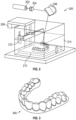
- An all-composite dental crown is formed using 3M ESPE SINFONY paste (available from 3M ESPE, St. Paul, MN) by building up the crown on a model in layers of at least one selected color of paste (e.g., including Opaque paste O A0 - O D4, Dentin paste D A0 - D D4, Incisal paste E1 - E4, Intensive-Opaque paste IO 1 - IO 5, Opaque-Dentin paste DO1 - DO 5, Enamel-effect paste E5 - E6, Magic Intensive paste I1 - I11, and/or Transparent-Opal paste T1-T4), each layer having a maximum 1 millimeter thickness.
- 3M ESPE SINFONY paste available from 3M ESPE, St. Paul, MN
- Each layer is polymerized using a VISIO Alfa curing device (available from 3M ESPE) prior to applying the next layer.
- the crown is lifted off the model and placed in the apparatus according to the first aspect described in detail above.
- Final polymerization of the dental crown is conducted in the apparatus for 1 minute of light exposure using a wavelength spectrum of 400-500 nm without vacuum, followed by 14 minutes of light exposure with vacuum of 0.1 mbar, also at a wavelength spectrum 400-500 nm.
Landscapes
- Health & Medical Sciences (AREA)
- Veterinary Medicine (AREA)
- Engineering & Computer Science (AREA)
- Epidemiology (AREA)
- Life Sciences & Earth Sciences (AREA)
- Animal Behavior & Ethology (AREA)
- General Health & Medical Sciences (AREA)
- Public Health (AREA)
- Oral & Maxillofacial Surgery (AREA)
- Dentistry (AREA)
- Chemical & Material Sciences (AREA)
- Materials Engineering (AREA)
- Optics & Photonics (AREA)
- Physics & Mathematics (AREA)
- Manufacturing & Machinery (AREA)
- Mechanical Engineering (AREA)
- Polymerisation Methods In General (AREA)
- Heating, Cooling, Or Curing Plastics Or The Like In General (AREA)
Claims (13)
- Eine Einrichtung (1000), aufweisend:a) ein Gehäuse (110);b) eine Kammer (120), die in dem Gehäuse (110) angeordnet ist, wobei die Kammer (120) konfiguriert ist, um an jede von einer geöffneten Konfiguration, einer geschlossenen Konfiguration und einer hermetisch abgedichteten Konfiguration anpassbar zu sein, wobei die Kammer (120) ein für aktinische Strahlung durchlässiges Material aufweist;c) mindestens zwei Leuchtdioden, LEDs, (130), die innerhalb des Gehäuses (110) angeordnet sind, wobei Licht von den mindestens zwei LEDs (130) aus mehr als einer Richtung in die Kammer (120) eintritt;d) eine Vakuumpumpe (150), die mit der Kammer (120) wirkverbunden ist; unde) eine Benutzerschnittstelle (140), die an einer Außenseite (112) des Gehäuses (110) angeordnet ist, wobei die Benutzerschnittstelle (140) eine Anzeige (142) und eine Mehrzahl von Programmschaltern (144) aufweist, die konfiguriert sind, um mindestens drei Betriebsparameter der Einrichtung (1000) einzustellen, wobei die mindestens drei Betriebsparameter 1) eine Lichtintensität, die durch die mindestens zwei LEDs (130) bereitgestellt wird, 2) eine Lichtdauer, die durch die mindestens zwei LEDs (130) bereitgestellt wird, und mindestens eines aufweisen von: 3a) einer Verzögerungszeit zwischen einem Initiieren von Licht, das durch die mindestens zwei LEDs (130) bereitgestellt wird, und einem Initiieren von Vakuum, das an einer Innenseite der Kammer durch die Vakuumpumpe gezogen wird, oder 3b) einer Verzögerungszeit zwischen einem Initiieren von Vakuum, das an einer Innenseite der Kammer durch die Vakuumpumpe gezogen wird, und einem Initiieren von Licht, das durch die mindestens zwei LEDs bereitgestellt wird.
- Die Einrichtung (1000) nach Anspruch 1, ferner aufweisend einen Prozessor (170), wobei der Prozessor (170) veranlasst, dass die mindestens zwei LEDs (130) Licht aussenden und die Vakuumpumpe (150) gemäß einem Programm betrieben wird, das über die Benutzerschnittstelle (140) eingegeben wird.
- Die Einrichtung (1000) nach Anspruch 2, wobei der Prozessor (170) ferner einen Speicher (172) aufweist und konfiguriert ist, um die mindestens zwei LEDs (130) zu veranlassen, Licht auszusenden und die Vakuumpumpe (150) gemäß einem Programm zu betreiben, das in dem Speicher (172) gespeichert ist.
- Die Einrichtung (1000) nach einem der Ansprüche 1 bis 3, wobei eine erste LED (130) positioniert ist, um Licht durch eine erste Hauptoberfläche der Kammer (121) zu leiten, und eine zweite LED (130) positioniert ist, um Licht durch eine gegenüberliegende zweite Hauptoberfläche der Kammer (123) zu leiten.
- Die Einrichtung (1000) nach einem der Ansprüche 1 bis 4, wobei die Benutzerschnittstelle (140) einen Touchscreen (143) aufweist, der die Anzeige (142) und die Mehrzahl von Programmschaltern (144) bereitstellt.
- Die Einrichtung (1000) nach einem der Ansprüche 1 bis 5, ferner aufweisend eine dritte LED (130), die positioniert ist, um Licht durch eine dritte Hauptoberfläche der Kammer (125) zu leiten, wobei die dritte Hauptoberfläche (125) direkt an jede der ersten Hauptoberfläche (121) und der zweiten Hauptoberfläche (123) angrenzt.
- Die Einrichtung (1000) nach einem der Ansprüche 1 bis 6, wobei die Kammer (120) ferner einen Verbinder aufweist, der konfiguriert ist, um eine Gasquelle (160) an die Kammer (120) anzuschließen.
- Die Einrichtung (1000) nach Anspruch 7, wobei die Mehrzahl von Programmschaltern (144) ferner konfiguriert ist, um eine Zeit zum Spülen der Kammer (120) mit einem Gas aus der Gasquelle (160) und/oder einen Druck zum Spülen der Kammer (120) mit dem Gas einzustellen.
- Die Einrichtung (1000) nach einem der Ansprüche 1 bis 8, wobei die Vakuumpumpe (150) konfiguriert ist, um im Inneren der Kammer (120) einen absoluten Druck von 0,1 bis 30 Millibar (mbar) zu erreichen.
- Ein Verfahren zum Nachhärten eines Gegenstands (180, 300, 1130), das Verfahren aufweisend:a) Erhalten eines Gegenstands (180, 300, 1130);b) Platzieren des Gegenstands (180, 300, 1130) in einer Einrichtung (1000), wobei die Einrichtung (1000) aufweist:1) ein Gehäuse (110);2) eine Kammer (120), die in dem Gehäuse (110) angeordnet ist, wobei die Kammer (120) konfiguriert ist, um an jede von einer geöffneten Konfiguration, einer geschlossenen Konfiguration und einer hermetisch abgedichteten Konfiguration anpassbar zu sein, wobei die Kammer (120) ein für aktinische Strahlung durchlässiges Material aufweist;3) mindestens eine Lichtquelle, aufweisend zwei Leuchtdioden, LEDs, (130), die innerhalb des Gehäuses (110) angeordnet sind;4) eine Benutzerschnittstelle (140), die an einer Außenseite (112) des Gehäuses (110) angeordnet ist, wobei die Benutzerschnittstelle (140) eine Anzeige (142) und eine Mehrzahl von Programmschaltern (144) aufweist, die konfiguriert sind, um mindestens drei Betriebsparameter der Einrichtung (1000) einzustellen; und5) eine Vakuumpumpe (150), die mit der Kammer (120) wirkverbunden ist;c) Eingeben eines Nachhärtungsprogramms oder Zugreifen auf ein gespeichertes Programm über die Benutzerschnittstelle (140), wobei das Nachhärtungsprogramm aufweist 1) eine Lichtintensität, die durch die mindestens eine Lichtquelle bereitgestellt wird, 2) eine Lichtdauer, die durch die mindestens eine Lichtquelle bereitgestellt wird, und mindestens eines von: 3a) einer Verzögerungszeit zwischen einem Initiieren von Licht, das durch die mindestens eine Lichtquelle bereitgestellt wird, und einem Initiieren von Vakuum, das an einer Innenseite der Kammer (120) durch die Vakuumpumpe (150) gezogen wird, oder 3b) einer Verzögerungszeit zwischen einem Initiieren von Vakuum, das an einer Innenseite der Kammer (120) durch die Vakuumpumpe (150) gezogen wird, und einem Initiieren von Licht, das durch die mindestens eine Lichtquelle bereitgestellt wird; undd) Ausführen des Nachhärtungsprogramms.
- Das Verfahren nach Anspruch 10, wobei die mindestens eine Lichtquelle eine Leuchtdiode, LED, (130) aufweist, die Licht bereitstellt, das eine Spitzenwellenlänge zwischen 250 nm und 500 nm einschließt.
- Das Verfahren nach Anspruch 10 oder 11, wobei das Erhalten des Gegenstands (180, 300, 1130) aufweist:I) Erhalten einer fotopolymerisierbaren Zusammensetzung;II) selektives Aushärten der fotopolymerisierbaren Zusammensetzung unter Verwendung von aktinischer Strahlung, um einen Gegenstand auszubilden, aufweisend eine Mehrzahl von Schichten von mindestens einer fotopolymerisierbaren Zusammensetzung; undIII) Entfernen von überschüssiger fotopolymerisierbarer Zusammensetzung von dem Gegenstand (180, 300, 1130).
- Ein System aufweisend:a) eine Einrichtung (1000) nach einem der Ansprüche 1 bis 9; undb) einen Gegenstand (180, 300, 1130), aufweisend mindestens eine fotopolymerisierte Zusammensetzung.
Applications Claiming Priority (2)
| Application Number | Priority Date | Filing Date | Title |
|---|---|---|---|
| US201962899417P | 2019-09-12 | 2019-09-12 | |
| PCT/IB2020/058330 WO2021048733A1 (en) | 2019-09-12 | 2020-09-08 | Apparatus, system, method of post-curing an article, and post-cured article |
Publications (2)
| Publication Number | Publication Date |
|---|---|
| EP4028252A1 EP4028252A1 (de) | 2022-07-20 |
| EP4028252B1 true EP4028252B1 (de) | 2025-06-04 |
Family
ID=72473595
Family Applications (1)
| Application Number | Title | Priority Date | Filing Date |
|---|---|---|---|
| EP20771627.5A Active EP4028252B1 (de) | 2019-09-12 | 2020-09-08 | Vorrichtung, system und verfahren zum nachhärten eines gegenstandes |
Country Status (5)
| Country | Link |
|---|---|
| US (2) | US12268567B2 (de) |
| EP (1) | EP4028252B1 (de) |
| JP (1) | JP2022548851A (de) |
| CN (1) | CN114340874B (de) |
| WO (1) | WO2021048733A1 (de) |
Families Citing this family (10)
| Publication number | Priority date | Publication date | Assignee | Title |
|---|---|---|---|---|
| EP3845504A1 (de) | 2019-12-30 | 2021-07-07 | Ivoclar Vivadent AG | Verfahren zur herstellung einer mehrfarbigen dentalrestauration |
| US11433619B1 (en) * | 2021-10-27 | 2022-09-06 | Sprintray Inc. | System and method for selectively post-curing parts printed with stereolithography additive manufacturing techniques |
| KR102273407B1 (ko) * | 2021-04-22 | 2021-07-07 | 주식회사 그래피 | 3d 프린트 출력물의 후경화 방법 및 이의 방법에 의해 제조된 투명 치아 교정 장치 |
| EP4166522A1 (de) * | 2021-10-14 | 2023-04-19 | Ivoclar Vivadent AG | Formgebungsgerät für ein dentalobjekt |
| EP4233784B1 (de) * | 2021-10-14 | 2024-12-04 | Ivoclar Vivadent AG | Belichtungsgerät zum beleuchten eines dentalobjekts |
| USD1038195S1 (en) | 2021-10-27 | 2024-08-06 | Sprintray, Inc. | Post-curing chamber |
| WO2023235635A1 (en) * | 2022-06-03 | 2023-12-07 | Dentsply Sirona Inc. | Methods for curing dental appliances |
| EP4642621A1 (de) * | 2022-12-29 | 2025-11-05 | Solventum Intellectual Properties Company | Vorrichtungen und verfahren zur nachbearbeitung von generativ gefertigten werkstücken |
| KR102575220B1 (ko) * | 2023-02-17 | 2023-09-06 | 송은영 | 치과용 하이브리드 복합 레진블록의 제작을 위한 광 중합기 |
| EP4464490A1 (de) * | 2023-05-15 | 2024-11-20 | Dymax Engineering Adhesives Ireland Ltd. | Kammer zum härten eines werkstücks |
Citations (1)
| Publication number | Priority date | Publication date | Assignee | Title |
|---|---|---|---|---|
| EP3378435B1 (de) * | 2017-03-20 | 2021-06-16 | Effegi Brega S.r.L. | Verfahren und vorrichtung zur polymerisation oder vernetzung einer zahnmittelzusammensetzung |
Family Cites Families (124)
| Publication number | Priority date | Publication date | Assignee | Title |
|---|---|---|---|---|
| US3076363A (en) | 1950-11-18 | 1963-02-05 | Schenck Gmbh Carl | Means for machining rotating workpieces |
| GB825389A (en) | 1957-02-07 | 1959-12-16 | Andre Robert Zenouda | Improvements in or relating to apparatus for cleaning the bit of a dental drill |
| DE1966274C3 (de) | 1969-03-11 | 1979-07-05 | Fa. Andreas Hettich, 7200 Tuttlingen | Zentrifuge mit einem Schleuderkopf zur Aufnahme von durchsichtigen Probengefäßen |
| DE8007265U1 (de) | 1980-03-17 | 1981-08-27 | ESPE Fabrik pharmazeutischer Präparate GmbH, 8031 Seefeld | Geraet zum behandeln von zahnersatzteilen |
| DE3209547A1 (de) | 1981-03-16 | 1982-10-21 | ESPE Fabrik pharmazeutischer Präparate GmbH, 8031 Seefeld | Geraet zum behandeln von zahnersatzteilen |
| US4412134A (en) | 1981-07-15 | 1983-10-25 | Espe Fabrik Pharmazeutischer Praeparate Gmbh | Apparatus for irradiating dental objects |
| DE3212379A1 (de) | 1982-04-02 | 1983-10-20 | ESPE Fabrik pharmazeutischer Präparate GmbH, 8031 Seefeld | Geraet zum behandeln von dentalen werkstoffen |
| JPS625A (ja) | 1985-06-24 | 1987-01-06 | Sankin Kogyo Kk | 歯科用レジンの表面被覆剤 |
| AU4504089A (en) | 1988-10-05 | 1990-05-01 | Michael Feygin | An improved apparatus and method for forming an integral object from laminations |
| WO1991004798A1 (en) | 1989-09-29 | 1991-04-18 | 3D Systems, Inc. | Methods of coating stereolithographic parts |
| DK217790A (da) * | 1990-09-11 | 1992-03-12 | Gn Danavox As | Fremgangsmaade og apparat til haerdning af stoebelige materialer, samt anvendelse heraf |
| JP3013498B2 (ja) | 1991-05-21 | 2000-02-28 | 東レ株式会社 | 水なし平版印刷版用現像液 |
| US5482659A (en) | 1994-12-22 | 1996-01-09 | United Technologies Corporation | Method of post processing stereolithographically produced objects |
| EP0796172B1 (de) | 1995-10-06 | 1999-12-22 | Polaroid Corporation | Auf der druckpress entwickelbare druckplatten mit ausbildendem wasserstoffbrücken entwicklungstabilisator |
| JPH09193159A (ja) | 1996-01-19 | 1997-07-29 | Sumitomo Rubber Ind Ltd | タイヤの加硫方法及びそれに用いられるポストキュアボックス |
| US5741368A (en) | 1996-01-30 | 1998-04-21 | Silicon Valley Chemlabs | Dibasic ester stripping composition |
| WO1999021658A1 (en) | 1997-10-27 | 1999-05-06 | Michael Yavilevich | Combined centrifugation assembly |
| US5901593A (en) | 1998-01-26 | 1999-05-11 | Northrop Grumman Corporation | Making hydropress formblocks and dies utilizing stereolithography and liquid molding compounds |
| US6579917B1 (en) | 1999-02-24 | 2003-06-17 | Sanyo Electric Co., Ltd. | Surface treatment agent for model |
| JP2000318048A (ja) | 1999-05-10 | 2000-11-21 | Jsr Corp | 光造形物の後処理法および成形型 |
| DE19936931A1 (de) | 1999-08-05 | 2001-02-08 | Dieter Fichtner | Verfahren und Steueranordnung zur Glättung der Kontur von stereolithografisch hergestellten Bauteilen |
| US6482576B1 (en) | 2000-08-08 | 2002-11-19 | Micron Technology, Inc. | Surface smoothing of stereolithographically formed 3-D objects |
| US6624128B1 (en) | 2001-03-30 | 2003-09-23 | Dixie Chemical Company | Water miscible composition containing a carboxylic acid diester and a fatty acid salt |
| US7186108B2 (en) * | 2002-04-11 | 2007-03-06 | Pentron Laboratory Technologies, Llc | Curing unit for dental materials |
| KR100938451B1 (ko) | 2002-04-17 | 2010-01-25 | 스트래터시스,인코포레이티드 | 층상 증착 모델링용 평활법 |
| TWI221100B (en) | 2002-05-14 | 2004-09-21 | Yi-Jeng Wang | Process method and system for saving cleaning water |
| US6833231B2 (en) | 2002-07-31 | 2004-12-21 | 3D Systems, Inc. | Toughened stereolithographic resin compositions |
| US6883792B2 (en) | 2002-09-16 | 2005-04-26 | Honda Motor Co., Ltd. | Workpiece positioner and method |
| US20040069770A1 (en) * | 2002-10-11 | 2004-04-15 | Schott Corporation | Glass/metal laminate for appliances |
| US20040159344A1 (en) | 2002-11-11 | 2004-08-19 | Hiatt William M. | Cleaning components for use with programmable material consolidation apparatus and systems |
| JP4352844B2 (ja) | 2003-10-09 | 2009-10-28 | 日立工機株式会社 | 遠心機 |
| US7546841B2 (en) | 2003-11-19 | 2009-06-16 | David Jonathan Tafoya | Apparatus and method of removing water soluble support material from a rapid prototype part |
| KR101474174B1 (ko) * | 2004-03-22 | 2014-12-17 | 3디 시스템즈 인코오퍼레이티드 | 광경화성 조성물 |
| DE102004025364A1 (de) | 2004-05-19 | 2005-12-08 | Basf Drucksysteme Gmbh | Verfahren zur Herstellung von Flexodruckformen mittels Laser-Direktgravur |
| US20050277084A1 (en) | 2004-06-10 | 2005-12-15 | 3M Innovative Properties Company | Orthodontic brace with polymeric arch member |
| JP2006255086A (ja) * | 2005-03-16 | 2006-09-28 | Oyama Yoshio | 歯科用義歯模型及び義歯の製造方法 |
| US20070031791A1 (en) | 2005-08-03 | 2007-02-08 | 3M Innovative Properties Company | Scanning models for digital orthodontics |
| JP2007151649A (ja) | 2005-12-01 | 2007-06-21 | Matsushita Electric Ind Co Ltd | 食器洗い機 |
| US8956457B2 (en) * | 2006-09-08 | 2015-02-17 | Tokyo Electron Limited | Thermal processing system for curing dielectric films |
| DE102006060720A1 (de) | 2006-12-21 | 2008-06-26 | Qimonda Ag | Verfahren zur Reduzierung der Rauhigkeit der Oberfläche einer Resistschicht |
| US8765045B2 (en) | 2007-01-12 | 2014-07-01 | Stratasys, Inc. | Surface-treatment method for rapid-manufactured three-dimensional objects |
| US20080276867A1 (en) * | 2007-05-09 | 2008-11-13 | Jason Schaller | Transfer chamber with vacuum extension for shutter disks |
| DK2011631T3 (da) | 2007-07-04 | 2012-06-25 | Envisiontec Gmbh | Fremgangsmåde og indretning til fremstilling af et tre-dimensionelt objekt |
| EP2376422A4 (de) | 2008-12-18 | 2012-12-12 | Invista Tech Sarl | Nebenproduktstromderivate aus einem cyclohexanoxidationsverfahren und verwendungsverfahren dafür |
| FR2941633B1 (fr) | 2009-02-05 | 2011-03-18 | Peugeot Citroen Automobiles Sa | Procede de nettoyage et de sechage d'une piece usinee et systeme pour la mise en oeuvre du procede. |
| CN101564719A (zh) | 2009-05-18 | 2009-10-28 | 西安亚美模具有限公司 | 一种降低光固化快速原型件表面粗糙度的方法 |
| JP2011000566A (ja) | 2009-06-22 | 2011-01-06 | Hitachi Maxell Ltd | 気液分離装置、水素製造装置及び燃料電池システム |
| DE102009061069A1 (de) | 2009-11-27 | 2011-06-22 | Metallschleiferei Schulz GmbH, 78112 | Spülflüssigkeit zum Herauslösen von Stützmaterial in dreidimensional gedruckten Modellen |
| ES2934103T3 (es) | 2011-01-31 | 2023-02-16 | Global Filtration Systems Dba Gulf Filtration Systems Inc | Aparato para fabricar objetos tridimensionales a partir de múltiples materiales solidificables |
| TWI448732B (zh) | 2012-05-03 | 2014-08-11 | Young Optics Inc | 立體打印裝置 |
| US9605175B2 (en) * | 2012-10-29 | 2017-03-28 | Ariste Medical, Llc | Polymer coating compositions and coated products |
| BR112015010983B8 (pt) | 2012-11-14 | 2021-04-13 | Dentsply Int Inc | método para produzir uma prótese dentária tridimensional por uma impressora 3d baseada em um método dlp (processador de luz digital) ou estereolitografia |
| CN102989595A (zh) | 2012-12-31 | 2013-03-27 | 王克诚 | 公转自转行星差速离心机 |
| TW201842404A (zh) | 2013-02-12 | 2018-12-01 | 美商Eipi系統公司 | 用於3d製造的方法與裝置 |
| US9360757B2 (en) | 2013-08-14 | 2016-06-07 | Carbon3D, Inc. | Continuous liquid interphase printing |
| CN103522546A (zh) | 2013-09-26 | 2014-01-22 | 瑞安市麦田网络科技有限公司 | 一种高精度激光光固3d打印机 |
| WO2015070165A1 (en) | 2013-11-11 | 2015-05-14 | Mosher Brent | Support structure removal for 3d printed parts |
| US9421582B1 (en) | 2014-01-28 | 2016-08-23 | Amerikam, Inc. | Pivoting centrifugal parts cleaner |
| WO2015131250A1 (en) | 2014-03-07 | 2015-09-11 | Sgat Pty Ltd | Three dimensional printer |
| CN103934940B (zh) | 2014-05-06 | 2017-02-22 | 刘彦君 | 一种应用于光固化快速成型的后处理装置及三维打印机 |
| TWI609769B (zh) | 2014-06-03 | 2018-01-01 | 三緯國際立體列印科技股份有限公司 | 立體結構與立體列印方法 |
| DE102014108633B9 (de) | 2014-06-18 | 2024-07-04 | Kulzer Gmbh | Vorrichtung und Verfahren zur Herstellung dreidimensionaler Objekte mittels Rapid-Prototyping |
| CN204076853U (zh) | 2014-10-22 | 2015-01-07 | 成都金采科技有限公司 | 一种粉末材料成形3d打印生产线 |
| WO2016062739A1 (en) | 2014-10-24 | 2016-04-28 | Xeikon Prepress N.V. | Stereolithography method and apparatus, and holder for use in such a method |
| US10160194B2 (en) | 2015-03-03 | 2018-12-25 | Xerox Corporation | Systems and methods for implementing high speed final surface curing for three dimensional (3D) printed parts and components |
| WO2016191538A1 (en) | 2015-05-26 | 2016-12-01 | Sharkninja Operating Llc | Spiralizer attachment for food processor system |
| WO2016191162A1 (en) | 2015-05-28 | 2016-12-01 | 3M Innovative Properties Company | Additive manufacturing process for producing ceramic articles using a sol containing nano-sized particles |
| FR3039438B1 (fr) | 2015-07-30 | 2017-08-18 | Michelin & Cie | Installation de nettoyage de plateaux de fabrication additive |
| CN205008301U (zh) | 2015-09-24 | 2016-02-03 | 东莞市汇通手板模型有限公司 | 一种sla光固化快速模型清洗系统 |
| WO2017059222A1 (en) * | 2015-10-01 | 2017-04-06 | Dsm Ip Assets B.V. | Liquid, hybrid uv/vis radiation curable resin compositions for additive fabrication |
| CN205058635U (zh) | 2015-10-30 | 2016-03-02 | 无限三维(青岛)打印技术有限公司 | 3d打印成型零件后处理平台 |
| US9740103B2 (en) * | 2015-11-09 | 2017-08-22 | Macdermid Printing Solutions, Llc | Method and apparatus for producing liquid flexographic printing plates |
| DE102015120211B4 (de) | 2015-11-23 | 2020-11-26 | Zippel Gmbh | Verfahrbare Haltevorrichtung für industriell zu reinigende Werkstücke und Maschinenbauteile |
| CN105436120B (zh) | 2015-11-27 | 2017-11-10 | 全椒县新华机械有限责任公司 | 一种旋转型柴油机气缸盖清洗控制设备 |
| CN105562395B (zh) | 2015-12-07 | 2018-07-24 | 浙江隐齿丽医学技术有限公司 | 自动化3d打印牙颌模型清洗固化系统 |
| WO2017108645A1 (en) | 2015-12-22 | 2017-06-29 | Ecole Polytechnique Federale De Lausanne (Epfl) | Method and device for fabrication of 3d multi - material (composite) parts by selective laser melting combined with laser welding and cutting |
| US11254841B2 (en) * | 2015-12-29 | 2022-02-22 | 3M Innovative Properties Company | Additive manufacturing methods for adhesives and adhesive articles |
| KR102541489B1 (ko) | 2016-02-26 | 2023-06-08 | 삼성전자주식회사 | 기판 세정 장치 및 이를 이용한 기판 세정 설비 |
| CN105754757B (zh) | 2016-03-31 | 2019-01-22 | 宁夏共享化工有限公司 | 一种3d呋喃树脂用强效清洗剂及其生产方法 |
| US10189057B2 (en) | 2016-07-08 | 2019-01-29 | General Electric Company | Powder removal enclosure for additively manufactured components |
| WO2018026640A2 (en) | 2016-08-03 | 2018-02-08 | 3M Innovative Properties Company | Device and method for progressively building up an object from a light hardenable material |
| EP3281729B1 (de) | 2016-08-12 | 2019-03-13 | SLM Solutions Group AG | Pulverbettschmelzvorrichtung und pulverzufuhrverfahren zur bereitstellung von rohmaterialpulver an eine pulverauftragsvorrichtung einer pulverbettschmelzvorrichtung |
| EP3504017B1 (de) | 2016-08-25 | 2022-03-30 | 3M Innovative Properties Company | Gefärbte härtbare zusammensetzung für verfahren zur additiven fertigung, 3-dimensionaler verbundstoffkörper und verwendung davon |
| DE102016216839A1 (de) | 2016-09-06 | 2018-03-08 | Siemens Aktiengesellschaft | Verfahren zum Austragen von Füllmaterial aus einem in einem Bauteil vorhandenen Hohlraum und Mittel zur Durchführung dieses Verfahrens |
| CA2941624A1 (en) | 2016-09-09 | 2018-03-09 | Kal Tire | Gravity assist system |
| KR101839946B1 (ko) | 2016-09-13 | 2018-03-22 | 주식회사 고영테크놀러지 | 의료용 스탠드 |
| CN106493943A (zh) | 2016-10-27 | 2017-03-15 | 广东奥基德信机电有限公司 | 一种后固化3d打印成型方法 |
| JP2018083300A (ja) * | 2016-11-21 | 2018-05-31 | ローランドディー.ジー.株式会社 | ポストキュア方法、光造形方法 |
| CN206287523U (zh) | 2016-12-21 | 2017-06-30 | 江山合创快速制造技术有限公司 | 一种基于3d打印的后期固化设备 |
| EP3559744A1 (de) | 2016-12-23 | 2019-10-30 | 3M Innovative Properties Company | Bedruckbare zusammensetzungen mit polymeren und polymerisierbaren komponenten, artikel und verfahren zur herstellung von artikeln daraus |
| CN206632024U (zh) | 2017-03-06 | 2017-11-14 | 浙江隐齿丽医学技术有限公司 | 牙颌模型喷淋清洗装置 |
| CN206589347U (zh) | 2017-04-01 | 2017-10-27 | 广州科苑新型材料有限公司 | 一种光固化快速成型件的快速清洗与后固化装置 |
| WO2018222395A1 (en) | 2017-05-29 | 2018-12-06 | 3M Innovative Properties Company | Use of a cleaning composition for 3d-printed articles and related process |
| WO2018231583A1 (en) | 2017-06-14 | 2018-12-20 | 3M Innovative Properties Company | Curable composition for producing a dental composite crown and process of production |
| US10118193B1 (en) | 2017-07-14 | 2018-11-06 | Rolence Enterprise Inc. | Light curing apparatus |
| KR102673971B1 (ko) | 2017-07-25 | 2024-06-12 | 솔벤텀 인텔렉추얼 프로퍼티즈 캄파니 | 우레탄 성분 및 반응성 희석제를 포함하는 광중합성 조성물, 물품, 및 방법 |
| KR102555173B1 (ko) | 2017-07-26 | 2023-07-12 | 쓰리엠 이노베이티브 프로퍼티즈 컴파니 | 적층 제조에 의해 물리적 물체를 제조하는 방법 |
| CN207140365U (zh) | 2017-09-14 | 2018-03-27 | 郑州迈客美客电子科技有限公司 | 用于光固化3d打印机的多功能固化箱 |
| CN108780636A (zh) | 2017-09-15 | 2018-11-09 | 深圳和而泰智能控制股份有限公司 | 蜂鸣器控制电路及蜂鸣器 |
| BR112020004476A2 (pt) | 2017-09-15 | 2020-09-08 | Novozymes A/S | processo para produção de um produto de fermentação, e, uso de uma combinação de enzimas |
| US10452070B2 (en) | 2017-09-15 | 2019-10-22 | Uber Technologies, Inc. | Context-specific tolerance for motion control in autonomous vehicles |
| KR102776790B1 (ko) | 2017-09-21 | 2025-03-10 | 다우 도레이 캄파니 리미티드 | 경화성 실리콘 조성물, 그것으로 이루어지는 광학 부재용 수지 시트 및 발광 디바이스 |
| CN208004270U (zh) | 2017-11-06 | 2018-10-26 | 青岛少海研磨科技有限公司 | 一种砂带生产用后固化装置 |
| TWI640418B (zh) | 2017-11-15 | 2018-11-11 | 國家中山科學研究院 | 積層製造加工槽及其積層製造設備 |
| CN207533520U (zh) | 2017-11-21 | 2018-06-26 | 深圳市云硕灯业有限公司 | 一种手提式led光固化机 |
| WO2019102304A1 (en) | 2017-11-21 | 2019-05-31 | 3M Innovative Properties Company | A method of making a physical object |
| WO2019104079A1 (en) | 2017-11-22 | 2019-05-31 | 3M Innovative Properties Company | Orthodontic articles comprising polymerized composition comprising at least two free-radical initiators |
| CN111615377A (zh) | 2017-11-22 | 2020-09-01 | 3M创新有限公司 | 包含含有带光引发基团的聚合物或大分子的固化的可自由基聚合组合物的正畸制品 |
| US11389276B2 (en) | 2017-11-22 | 2022-07-19 | 3M Innovative Properties Comany | Photopolymerizable compositions including a urethane component and a monofunctional reactive diluent, articles, and methods |
| EP3720618B1 (de) | 2017-12-08 | 2024-01-24 | 3M Innovative Properties Company | System und verfahren zum waschen eines 3d-druckobjekts |
| CN107890128A (zh) | 2017-12-20 | 2018-04-10 | 安德里茨(中国)有限公司 | 用于饲料后熟化器和烘干器的加热和保温系统 |
| WO2019175716A1 (en) | 2018-03-15 | 2019-09-19 | 3M Innovative Properties Company | Photopolymerizable compositions including a polypropylene oxide component, articles, and methods |
| WO2019179500A1 (zh) | 2018-03-22 | 2019-09-26 | 北京化工大学 | 一种基于3d打印技术的加工装置及方法 |
| CN208006262U (zh) | 2018-03-29 | 2018-10-26 | 宝鸡高新智能制造技术有限公司 | 一种光固化无支撑3d打印机 |
| EP3806774A4 (de) | 2018-06-29 | 2022-07-06 | 3M Innovative Properties Company | Mit einem polycarbonatdiol hergestellte kieferorthopädische artikel und verfahren zu ihrer herstellung |
| WO2020003197A2 (en) | 2018-06-29 | 2020-01-02 | 3M Innovative Properties Company | Orthodontic articles prepared using a polycarbonate diol, polymerizable compositions, and methods of making the articles |
| WO2020003169A1 (en) | 2018-06-29 | 2020-01-02 | 3M Innovative Properties Company | Orthodontic articles comprising cured free-radically polymerizable composition with improved strength in aqueous environment |
| DE102018119027A1 (de) | 2018-08-06 | 2020-02-06 | Kulzer Gmbh | Verfahren zur Herstellung eines Bauteils mit Stereolithographie |
| KR102175834B1 (ko) | 2018-09-07 | 2020-11-06 | 주식회사 포스코 | 코크스 오븐 가스 정제 방법 및 그 장치 |
| WO2020104873A1 (en) | 2018-11-19 | 2020-05-28 | 3M Innovative Properties Company | Orthodontic articles comprising polyester urethane (meth)acrylate polymer and monofunctional (meth)acrylate monomer, methods, and polymerizable compositions |
| EP3917445B1 (de) | 2019-01-29 | 2025-11-05 | Solventum Intellectual Properties Company | Verfahren zur herstellung und nachbearbeitung von kieferorthopädischen artikeln |
| CN114174242A (zh) | 2019-08-06 | 2022-03-11 | 3M创新有限公司 | 用于制备陶瓷制品的连续叠层制造方法及陶瓷制品 |
| EP3789416A1 (de) * | 2019-09-04 | 2021-03-10 | Henkel AG & Co. KGaA | Thiol/isocyanat/(poly-)en-formulierungen zur generativen fertigung |
| US11155028B1 (en) | 2020-04-24 | 2021-10-26 | Sprintray Inc. | Apparatus and method for three-dimensional printing |
-
2020
- 2020-09-08 EP EP20771627.5A patent/EP4028252B1/de active Active
- 2020-09-08 US US17/637,488 patent/US12268567B2/en active Active
- 2020-09-08 CN CN202080062301.0A patent/CN114340874B/zh active Active
- 2020-09-08 JP JP2022515992A patent/JP2022548851A/ja active Pending
- 2020-09-08 WO PCT/IB2020/058330 patent/WO2021048733A1/en not_active Ceased
-
2025
- 2025-03-05 US US19/071,398 patent/US20250195191A1/en active Pending
Patent Citations (1)
| Publication number | Priority date | Publication date | Assignee | Title |
|---|---|---|---|---|
| EP3378435B1 (de) * | 2017-03-20 | 2021-06-16 | Effegi Brega S.r.L. | Verfahren und vorrichtung zur polymerisation oder vernetzung einer zahnmittelzusammensetzung |
Also Published As
| Publication number | Publication date |
|---|---|
| US12268567B2 (en) | 2025-04-08 |
| CN114340874A (zh) | 2022-04-12 |
| US20250195191A1 (en) | 2025-06-19 |
| US20220273409A1 (en) | 2022-09-01 |
| WO2021048733A1 (en) | 2021-03-18 |
| JP2022548851A (ja) | 2022-11-22 |
| CN114340874B (zh) | 2024-06-14 |
| EP4028252A1 (de) | 2022-07-20 |
Similar Documents
| Publication | Publication Date | Title |
|---|---|---|
| EP4028252B1 (de) | Vorrichtung, system und verfahren zum nachhärten eines gegenstandes | |
| KR102673971B1 (ko) | 우레탄 성분 및 반응성 희석제를 포함하는 광중합성 조성물, 물품, 및 방법 | |
| JP7223693B2 (ja) | ポリマー及び重合性成分を含むプリント可能な組成物、物品、並びにそれから物品を製造する方法 | |
| JP7038549B2 (ja) | オブジェクトを迅速に生産するための三次元製作方法 | |
| Watts et al. | Intrinsic ‘soft-start’polymerisation shrinkage-kinetics in an acrylate-based resin-composite | |
| Yamasaki et al. | Polymerization development of “low-shrink” resin composites: Reaction kinetics, polymerization stress and quality of network | |
| JP6423960B2 (ja) | ステレオリソグラフィ方法および組成物 | |
| EP3883521A1 (de) | Orthodontische artikel mit polyesterurethan-(meth)acrylatpolymer und monofunktionellem (meth)acrylatmonomer, verfahren und polymerisierbare zusammensetzungen | |
| US20210196436A1 (en) | Articles including a coupling to engage a tool, kits, additive manufacturing methods of making same, and methods of computing models of the articles | |
| KR20200130464A (ko) | 폴리카르보네이트 다이올을 사용하여 제조된 폴리우레탄 메타크릴레이트 중합체를 포함하는 광중합성 조성물, 물품, 및 방법 | |
| US11759299B2 (en) | Dental stereolithography-type three-dimensional printing material for preparing dental three-dimensional modeled object | |
| JP2011505973A (ja) | 部分的に硬化した組成物を有する歯科矯正用物品並びにその使用及び製造方法 | |
| EP3806774A1 (de) | Mit einem polycarbonatdiol hergestellte kieferorthopädische artikel und verfahren zu ihrer herstellung | |
| US20030069326A1 (en) | Curing method and material compositions having dental and other applications | |
| TW201509434A (zh) | 製造人工牙的方法 | |
| CN109716234A (zh) | 包括高度粘稠组分的可打印组合物和由其形成3d制品的方法 | |
| US20210361389A1 (en) | Hydrated orthodontic articles, kits, and methods of making same | |
| US20170056299A1 (en) | Kit of parts, method of producing and use thereof | |
| JP6865898B2 (ja) | シラン処理された表面を有する歯科用無機充填剤 | |
| Jerri | Evaluate polymer degree of conversion of bulk-fill composite restoration | |
| WO2020003133A1 (en) | Hydrated orthodontic articles, kits, and methods of making same | |
| JP7521898B2 (ja) | 歯科用修復材組成物 | |
| Chesnokov et al. | General conditions and experimental design of sustained frontal photopolymerization in photopolymerizable liquid compositions | |
| JP2022047507A (ja) | 光硬化性組成物及びその硬化物 | |
| JP2019178105A (ja) | 歯科切削加工用レジン材料の製造方法 |
Legal Events
| Date | Code | Title | Description |
|---|---|---|---|
| STAA | Information on the status of an ep patent application or granted ep patent |
Free format text: STATUS: UNKNOWN |
|
| STAA | Information on the status of an ep patent application or granted ep patent |
Free format text: STATUS: THE INTERNATIONAL PUBLICATION HAS BEEN MADE |
|
| PUAI | Public reference made under article 153(3) epc to a published international application that has entered the european phase |
Free format text: ORIGINAL CODE: 0009012 |
|
| STAA | Information on the status of an ep patent application or granted ep patent |
Free format text: STATUS: REQUEST FOR EXAMINATION WAS MADE |
|
| 17P | Request for examination filed |
Effective date: 20220217 |
|
| AK | Designated contracting states |
Kind code of ref document: A1 Designated state(s): AL AT BE BG CH CY CZ DE DK EE ES FI FR GB GR HR HU IE IS IT LI LT LU LV MC MK MT NL NO PL PT RO RS SE SI SK SM TR |
|
| DAV | Request for validation of the european patent (deleted) | ||
| DAX | Request for extension of the european patent (deleted) | ||
| RAP1 | Party data changed (applicant data changed or rights of an application transferred) |
Owner name: SOLVENTUM INTELLECTUAL PROPERTIES COMPANY |
|
| GRAP | Despatch of communication of intention to grant a patent |
Free format text: ORIGINAL CODE: EPIDOSNIGR1 |
|
| STAA | Information on the status of an ep patent application or granted ep patent |
Free format text: STATUS: GRANT OF PATENT IS INTENDED |
|
| RIC1 | Information provided on ipc code assigned before grant |
Ipc: A61C 13/00 20060101ALN20250203BHEP Ipc: B29C 64/124 20170101ALN20250203BHEP Ipc: B29C 35/08 20060101ALN20250203BHEP Ipc: B33Y 40/20 20200101ALI20250203BHEP Ipc: A61C 13/15 20060101ALI20250203BHEP Ipc: B29C 71/04 20060101AFI20250203BHEP |
|
| INTG | Intention to grant announced |
Effective date: 20250213 |
|
| GRAS | Grant fee paid |
Free format text: ORIGINAL CODE: EPIDOSNIGR3 |
|
| GRAJ | Information related to disapproval of communication of intention to grant by the applicant or resumption of examination proceedings by the epo deleted |
Free format text: ORIGINAL CODE: EPIDOSDIGR1 |
|
| GRAL | Information related to payment of fee for publishing/printing deleted |
Free format text: ORIGINAL CODE: EPIDOSDIGR3 |
|
| STAA | Information on the status of an ep patent application or granted ep patent |
Free format text: STATUS: REQUEST FOR EXAMINATION WAS MADE |
|
| GRAP | Despatch of communication of intention to grant a patent |
Free format text: ORIGINAL CODE: EPIDOSNIGR1 |
|
| STAA | Information on the status of an ep patent application or granted ep patent |
Free format text: STATUS: GRANT OF PATENT IS INTENDED |
|
| GRAA | (expected) grant |
Free format text: ORIGINAL CODE: 0009210 |
|
| STAA | Information on the status of an ep patent application or granted ep patent |
Free format text: STATUS: THE PATENT HAS BEEN GRANTED |
|
| INTC | Intention to grant announced (deleted) | ||
| RIC1 | Information provided on ipc code assigned before grant |
Ipc: A61C 13/00 20060101ALN20250409BHEP Ipc: B29C 64/124 20170101ALN20250409BHEP Ipc: B29C 35/08 20060101ALN20250409BHEP Ipc: B33Y 40/20 20200101ALI20250409BHEP Ipc: A61C 13/15 20060101ALI20250409BHEP Ipc: B29C 71/04 20060101AFI20250409BHEP |
|
| INTG | Intention to grant announced |
Effective date: 20250416 |
|
| AK | Designated contracting states |
Kind code of ref document: B1 Designated state(s): AL AT BE BG CH CY CZ DE DK EE ES FI FR GB GR HR HU IE IS IT LI LT LU LV MC MK MT NL NO PL PT RO RS SE SI SK SM TR |
|
| REG | Reference to a national code |
Ref country code: GB Ref legal event code: FG4D |
|
| REG | Reference to a national code |
Ref country code: CH Ref legal event code: EP |
|
| REG | Reference to a national code |
Ref country code: DE Ref legal event code: R096 Ref document number: 602020052318 Country of ref document: DE |
|
| REG | Reference to a national code |
Ref country code: IE Ref legal event code: FG4D |
|
| REG | Reference to a national code |
Ref country code: NL Ref legal event code: MP Effective date: 20250604 |
|
| PG25 | Lapsed in a contracting state [announced via postgrant information from national office to epo] |
Ref country code: FI Free format text: LAPSE BECAUSE OF FAILURE TO SUBMIT A TRANSLATION OF THE DESCRIPTION OR TO PAY THE FEE WITHIN THE PRESCRIBED TIME-LIMIT Effective date: 20250604 Ref country code: ES Free format text: LAPSE BECAUSE OF FAILURE TO SUBMIT A TRANSLATION OF THE DESCRIPTION OR TO PAY THE FEE WITHIN THE PRESCRIBED TIME-LIMIT Effective date: 20250604 |
|
| PGFP | Annual fee paid to national office [announced via postgrant information from national office to epo] |
Ref country code: DE Payment date: 20250820 Year of fee payment: 6 |
|
| REG | Reference to a national code |
Ref country code: LT Ref legal event code: MG9D |
|
| PG25 | Lapsed in a contracting state [announced via postgrant information from national office to epo] |
Ref country code: NO Free format text: LAPSE BECAUSE OF FAILURE TO SUBMIT A TRANSLATION OF THE DESCRIPTION OR TO PAY THE FEE WITHIN THE PRESCRIBED TIME-LIMIT Effective date: 20250904 Ref country code: GR Free format text: LAPSE BECAUSE OF FAILURE TO SUBMIT A TRANSLATION OF THE DESCRIPTION OR TO PAY THE FEE WITHIN THE PRESCRIBED TIME-LIMIT Effective date: 20250905 |
|
| PG25 | Lapsed in a contracting state [announced via postgrant information from national office to epo] |
Ref country code: PL Free format text: LAPSE BECAUSE OF FAILURE TO SUBMIT A TRANSLATION OF THE DESCRIPTION OR TO PAY THE FEE WITHIN THE PRESCRIBED TIME-LIMIT Effective date: 20250604 |
|
| PG25 | Lapsed in a contracting state [announced via postgrant information from national office to epo] |
Ref country code: BG Free format text: LAPSE BECAUSE OF FAILURE TO SUBMIT A TRANSLATION OF THE DESCRIPTION OR TO PAY THE FEE WITHIN THE PRESCRIBED TIME-LIMIT Effective date: 20250604 |
|
| PG25 | Lapsed in a contracting state [announced via postgrant information from national office to epo] |
Ref country code: HR Free format text: LAPSE BECAUSE OF FAILURE TO SUBMIT A TRANSLATION OF THE DESCRIPTION OR TO PAY THE FEE WITHIN THE PRESCRIBED TIME-LIMIT Effective date: 20250604 |
|
| PG25 | Lapsed in a contracting state [announced via postgrant information from national office to epo] |
Ref country code: RS Free format text: LAPSE BECAUSE OF FAILURE TO SUBMIT A TRANSLATION OF THE DESCRIPTION OR TO PAY THE FEE WITHIN THE PRESCRIBED TIME-LIMIT Effective date: 20250904 |
|
| PG25 | Lapsed in a contracting state [announced via postgrant information from national office to epo] |
Ref country code: LV Free format text: LAPSE BECAUSE OF FAILURE TO SUBMIT A TRANSLATION OF THE DESCRIPTION OR TO PAY THE FEE WITHIN THE PRESCRIBED TIME-LIMIT Effective date: 20250604 |
|
| PG25 | Lapsed in a contracting state [announced via postgrant information from national office to epo] |
Ref country code: NL Free format text: LAPSE BECAUSE OF FAILURE TO SUBMIT A TRANSLATION OF THE DESCRIPTION OR TO PAY THE FEE WITHIN THE PRESCRIBED TIME-LIMIT Effective date: 20250604 |
|
| PG25 | Lapsed in a contracting state [announced via postgrant information from national office to epo] |
Ref country code: PT Free format text: LAPSE BECAUSE OF FAILURE TO SUBMIT A TRANSLATION OF THE DESCRIPTION OR TO PAY THE FEE WITHIN THE PRESCRIBED TIME-LIMIT Effective date: 20251006 |
|
| REG | Reference to a national code |
Ref country code: AT Ref legal event code: MK05 Ref document number: 1799967 Country of ref document: AT Kind code of ref document: T Effective date: 20250604 |