EP4023575A1 - Umlenkeinrichtung für produkte - Google Patents
Umlenkeinrichtung für produkte Download PDFInfo
- Publication number
- EP4023575A1 EP4023575A1 EP21217008.8A EP21217008A EP4023575A1 EP 4023575 A1 EP4023575 A1 EP 4023575A1 EP 21217008 A EP21217008 A EP 21217008A EP 4023575 A1 EP4023575 A1 EP 4023575A1
- Authority
- EP
- European Patent Office
- Prior art keywords
- transport
- deflection
- products
- rotation
- area
- Prior art date
- Legal status (The legal status is an assumption and is not a legal conclusion. Google has not performed a legal analysis and makes no representation as to the accuracy of the status listed.)
- Granted
Links
Images


Classifications
-
- B—PERFORMING OPERATIONS; TRANSPORTING
- B65—CONVEYING; PACKING; STORING; HANDLING THIN OR FILAMENTARY MATERIAL
- B65G—TRANSPORT OR STORAGE DEVICES, e.g. CONVEYORS FOR LOADING OR TIPPING, SHOP CONVEYOR SYSTEMS OR PNEUMATIC TUBE CONVEYORS
- B65G47/00—Article or material-handling devices associated with conveyors; Methods employing such devices
- B65G47/02—Devices for feeding articles or materials to conveyors
- B65G47/04—Devices for feeding articles or materials to conveyors for feeding articles
- B65G47/06—Devices for feeding articles or materials to conveyors for feeding articles from a single group of articles arranged in orderly pattern, e.g. workpieces in magazines
- B65G47/08—Devices for feeding articles or materials to conveyors for feeding articles from a single group of articles arranged in orderly pattern, e.g. workpieces in magazines spacing or grouping the articles during feeding
- B65G47/082—Devices for feeding articles or materials to conveyors for feeding articles from a single group of articles arranged in orderly pattern, e.g. workpieces in magazines spacing or grouping the articles during feeding grouping articles in rows
-
- B—PERFORMING OPERATIONS; TRANSPORTING
- B65—CONVEYING; PACKING; STORING; HANDLING THIN OR FILAMENTARY MATERIAL
- B65G—TRANSPORT OR STORAGE DEVICES, e.g. CONVEYORS FOR LOADING OR TIPPING, SHOP CONVEYOR SYSTEMS OR PNEUMATIC TUBE CONVEYORS
- B65G29/00—Rotary conveyors, e.g. rotating discs, arms, star-wheels or cones
-
- B—PERFORMING OPERATIONS; TRANSPORTING
- B65—CONVEYING; PACKING; STORING; HANDLING THIN OR FILAMENTARY MATERIAL
- B65B—MACHINES, APPARATUS OR DEVICES FOR, OR METHODS OF, PACKAGING ARTICLES OR MATERIALS; UNPACKING
- B65B35/00—Supplying, feeding, arranging or orientating articles to be packaged
- B65B35/56—Orientating, i.e. changing the attitude of, articles, e.g. of non-uniform cross-section
- B65B35/58—Turning articles by positively-acting means, e.g. to present labelled portions in uppermost position
-
- B—PERFORMING OPERATIONS; TRANSPORTING
- B65—CONVEYING; PACKING; STORING; HANDLING THIN OR FILAMENTARY MATERIAL
- B65B—MACHINES, APPARATUS OR DEVICES FOR, OR METHODS OF, PACKAGING ARTICLES OR MATERIALS; UNPACKING
- B65B35/00—Supplying, feeding, arranging or orientating articles to be packaged
- B65B35/10—Feeding, e.g. conveying, single articles
- B65B35/24—Feeding, e.g. conveying, single articles by endless belts or chains
-
- B—PERFORMING OPERATIONS; TRANSPORTING
- B65—CONVEYING; PACKING; STORING; HANDLING THIN OR FILAMENTARY MATERIAL
- B65G—TRANSPORT OR STORAGE DEVICES, e.g. CONVEYORS FOR LOADING OR TIPPING, SHOP CONVEYOR SYSTEMS OR PNEUMATIC TUBE CONVEYORS
- B65G21/00—Supporting or protective framework or housings for endless load-carriers or traction elements of belt or chain conveyors
- B65G21/20—Means incorporated in, or attached to, framework or housings for guiding load-carriers, traction elements or loads supported on moving surfaces
- B65G21/2045—Mechanical means for guiding or retaining the load on the load-carrying surface
- B65G21/2054—Mechanical means for guiding or retaining the load on the load-carrying surface comprising elements movable in the direction of load-transport
-
- B—PERFORMING OPERATIONS; TRANSPORTING
- B65—CONVEYING; PACKING; STORING; HANDLING THIN OR FILAMENTARY MATERIAL
- B65G—TRANSPORT OR STORAGE DEVICES, e.g. CONVEYORS FOR LOADING OR TIPPING, SHOP CONVEYOR SYSTEMS OR PNEUMATIC TUBE CONVEYORS
- B65G47/00—Article or material-handling devices associated with conveyors; Methods employing such devices
- B65G47/52—Devices for transferring articles or materials between conveyors i.e. discharging or feeding devices
-
- B—PERFORMING OPERATIONS; TRANSPORTING
- B65—CONVEYING; PACKING; STORING; HANDLING THIN OR FILAMENTARY MATERIAL
- B65G—TRANSPORT OR STORAGE DEVICES, e.g. CONVEYORS FOR LOADING OR TIPPING, SHOP CONVEYOR SYSTEMS OR PNEUMATIC TUBE CONVEYORS
- B65G47/00—Article or material-handling devices associated with conveyors; Methods employing such devices
- B65G47/52—Devices for transferring articles or materials between conveyors i.e. discharging or feeding devices
- B65G47/68—Devices for transferring articles or materials between conveyors i.e. discharging or feeding devices adapted to receive articles arriving in one layer from one conveyor lane and to transfer them in individual layers to more than one conveyor lane or to one broader conveyor lane, or vice versa, e.g. combining the flows of articles conveyed by more than one conveyor
- B65G47/682—Devices for transferring articles or materials between conveyors i.e. discharging or feeding devices adapted to receive articles arriving in one layer from one conveyor lane and to transfer them in individual layers to more than one conveyor lane or to one broader conveyor lane, or vice versa, e.g. combining the flows of articles conveyed by more than one conveyor from a single conveyor lane consisting of one conveyor or several adjacent conveyors
- B65G47/683—Devices for transferring articles or materials between conveyors i.e. discharging or feeding devices adapted to receive articles arriving in one layer from one conveyor lane and to transfer them in individual layers to more than one conveyor lane or to one broader conveyor lane, or vice versa, e.g. combining the flows of articles conveyed by more than one conveyor from a single conveyor lane consisting of one conveyor or several adjacent conveyors with tilting of at least part of the conveyor to make use of gravity
-
- B—PERFORMING OPERATIONS; TRANSPORTING
- B65—CONVEYING; PACKING; STORING; HANDLING THIN OR FILAMENTARY MATERIAL
- B65G—TRANSPORT OR STORAGE DEVICES, e.g. CONVEYORS FOR LOADING OR TIPPING, SHOP CONVEYOR SYSTEMS OR PNEUMATIC TUBE CONVEYORS
- B65G13/00—Roller-ways
- B65G13/08—Roller-ways of curved form; with branch-offs
- B65G13/10—Switching arrangements
-
- B—PERFORMING OPERATIONS; TRANSPORTING
- B65—CONVEYING; PACKING; STORING; HANDLING THIN OR FILAMENTARY MATERIAL
- B65G—TRANSPORT OR STORAGE DEVICES, e.g. CONVEYORS FOR LOADING OR TIPPING, SHOP CONVEYOR SYSTEMS OR PNEUMATIC TUBE CONVEYORS
- B65G2201/00—Indexing codes relating to handling devices, e.g. conveyors, characterised by the type of product or load being conveyed or handled
- B65G2201/02—Articles
- B65G2201/0202—Agricultural and processed food products
Definitions
- the present invention relates to a deflection device for a transport device for transporting products according to claim 1, as well as a transport path for transporting products according to claim 10 and a packaging machine for packaging products according to claim 13 and a method for packaging products according to claim 15.
- Transport devices for transporting products are known from the prior art. These usually include conveyor belts to transport products that may not have a fixed shape or size (such as sausages or other foods).
- the conveyor belts are usually configured as one or more driven belts. This allows for reliable transport, but mostly requires that transport be in a straight line only. Conveyor belts that have a curved shape and can therefore transport the products on curved paths are usually expensive and require a lot of space because of the radius of curvature that can be achieved.
- the technical problem to be solved is to specify a deflection device for a transport device for transporting products, with which a reliable deflection of products from a first to a second transport direction can be effected and at the same time space can be saved.
- the deflection area is to be understood here as an area in which the products are deflected, whereby they move from a first direction of movement (or first direction of transport) into a second direction of movement (or second direction of transport) due to the interaction with at least one of the first or second element. , which encloses an angle with the first direction of movement, are deflected. This is achieved in that the products, while they are being caused to move by the first and/or second element, at least in the deflection area, following the rotation of these elements, cannot leave the deflection area due to their mass inertia, since the deflection area is separated from the first and the second element is enclosed in this area due to its overlap in such a way that products cannot leave the deflection area.
- the centripetal force acting on the products during movement along the deflection area can cause deflection.
- the first and second element then no longer overlap, so that the products can no longer follow the rotation of the first and second element due to their mass inertia and can leave the deflection device.
- the size of the deflection area and thus also the deflection angle between the first direction of movement and the second direction of movement of the products can be determined by the geometry of the first and second element and/or the angle enclosed between the axes of rotation of the first and second element.
- first axis of rotation and the second axis of rotation intersect at one point.
- the truncated cone-shaped surface does not have to correspond exactly to the shape of a truncated cone here.
- the side surface of the truncated cone can also have curvatures or form no edges with the base surface and/or the top surface, but continuously merge into them (e.g. by segments of a circle instead of the edges).
- the side surface and/or the top surface and/or the base surface can be designed as a surface that comprises one or more concavely curved and/or convexly curved sections or elements in cross section parallel to the axis of symmetry of the truncated cone.
- the element in the form of a circular disk can in particular be designed in such a way that its diameter is greater than the height of the circular disk.
- the diameter of the circular disk-shaped first element can be five times larger than its height.
- An element in the form of a circular disk should not only include such realizations that do not include an opening located within the circular disk.
- elements which have a central opening for example for the passage of a rotary axis, and/or have additional openings in the area of the circular disc, for example in order to reduce its weight.
- a design that corresponds exactly to a circular disc is also not mandatory here.
- the circular disk-shaped element can also have irregularities on its surface, for example in order to increase the friction between the surface and a product.
- the first element in the shape of a circular disk can also have a circumferential indentation or groove on its side surface, in which products can be transported, in which case the second element can then preferably encompass this groove, so that a deflection area is enclosed.
- the frustoconical inner surface of the second member may preferably be formed such that the major and minor diameters of the truncated cone are greater than the height of the truncated cone forming the inner surface.
- the second element By designing the second element with an inner surface that is a truncated cone, a reliable Enclosing the first element can be realized in the form of a circular disk, so that products cannot unintentionally leave the deflection area and at the same time a reliable movement of the products through the deflection area is possible.
- the first element comprises two concentrically arranged circular disc-shaped segments spaced apart from one another along the first axis of rotation and rotatably mounted about the first axis of rotation, wherein a product can be received between the segments and transported through the deflection device and wherein the frustoconical surface of the second element encloses the two segments in the deflection area.
- the two mutually spaced circular disc-shaped segments do not necessarily have to be separate segments. They can also be connected to one another, for example by the common axis of rotation or another connecting element.
- the first element can be designed as a cylinder with circular disk-shaped segments extending along the top surface and along the base surface of the cylinder (approximately in the sense of an element with a double-T cross-section).
- the distance between the segments in the shape of a circular disk can be selected in particular in such a way that products can be transported between the segments in the shape of a circular disk. In connection with the configuration of the second element, a reliable transport of products can thus be ensured.
- an angle between the first axis of rotation and a side surface of the inner, frustoconical surface of the second element is between 0° and 20°, preferably between 0° and 5°, in at least a partial area of the deflection area.
- the first member is driven to rotate about the first axis of rotation by a first drive means and the second member is driven to rotate about the second axis of rotation by a second drive means independent of the first drive means.
- independent drives can reliably implement the movement of the first element and the second element even when the axes of rotation are tilted.
- the angular velocities of the first element and the second element can be reliably coordinated in this way.
- first element and the second element are driven by a common drive device for rotation about the first and the second axis of rotation. This can reduce the complexity of the turning device.
- the first drive device and the second drive device can drive the first element and the second element at the same speed.
- the same rotational speed ensures that the products transported with the deflection device experience no or only small undesired torques and thus assume incorrect positions during transport through the deflection device.
- This configuration is structurally simpler for the use of two independent drive devices and can thus advantageously reduce the complexity of the deflection device and its susceptibility to errors.
- the first element and/or the second element comprise a surface made of stainless steel that comes into contact with the product. Impurities or unintentional contamination of the products can thus be avoided.
- the angle between the feed direction and the discharge direction can advantageously be set by the angle that the axes of rotation of the first element and the second element enclose with one another.
- This angle can also be variably adjustable, so that the same deflection device can also be used in different configurations and/or arrangements of transport devices and the corresponding angle between the discharge direction and the feed direction can be set as required.
- a transport route for transporting products can also be provided, the transport route having a first transport device for transporting products along a first transport direction, a second transport device for transporting products along a second transport direction and a deflection device arranged between the first and the second transport device according to one of the preceding embodiments, wherein the first transport device can feed products to the deflection device and the deflection device can deflect products from the first transport direction into the second transport direction and the second Transport device can supply.
- This transport route can be made more compact, so that space can be saved in the production plant.
- V-shaped conveyor belts are usually used for products that do not have a fixed shape or at least not all have the same shape and may be flexible in shape, such as sausages. Reliable transport to and/or away from the deflection device is effected with this embodiment.
- the second transport device comprises a sliding area extending along the second transport direction for receiving products from the deflection device and a compartmented belt downstream of the sliding area, with products arriving from the sliding area into the compartmented belt and in the compartmented belt along a third transport direction can be transported.
- the products can be placed, for example, in suitable receiving troughs of the compartmented belt and then transported further.
- the third transport direction can enclose an angle that is not equal to zero with the second transport direction, in particular running transversely to the second transport direction.
- the packaging system comprising a treatment machine for products and a packaging machine for packaging products and a transport path according to one of the preceding embodiments downstream of the treatment machine and upstream of the packaging machine.
- Directions downstream are to be understood in the direction of the direction of transport of the products, directions upstream correspondingly opposite to the direction of transport.
- This embodiment implements a packaging system with a reduced space requirement for the transport routes between adjacent machines, in particular the treatment machine and the packaging machine.
- the treatment machine is or includes a centrifuge. Centrifuges come into consideration here, for example, for separating products such as sausages. With this The packaging system is designed for special use in the food industry.
- According to the invention is also a method for transporting products, the products being deflected from a first transport direction into a second transport direction by means of a deflection device according to one of the preceding embodiments.
- This method realizes an effective transport of products with shortened transport routes.
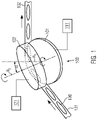
- FIG. 1 shows a deflection device 100 according to one embodiment in connection with a first transport device 131 arranged upstream of the deflection device in the transport direction and a second transport device 132 arranged downstream of the deflection device 100.
- These devices 100, 131 and 132 can be viewed together as a transport route. All of the embodiments mentioned below in relation to the deflection device can also be applied to a corresponding transport route.
- the deflection device 100 is designed and arranged to deflect the direction of movement of products 130 that are fed to it from the first transport device 131, for example, and to deflect the direction of movement of the second transport device 132, the transport direction of which can differ from the transport direction of the first transport device 131. to supply
- the transport devices 131, 132 can be designed as conveyor belts.
- one of the transport devices 131, 132 or both can be designed as a V-shaped conveyor belt, which comprises two conveyor belts arranged at an acute angle to one another, with products 130 being able to be transported in the trough thus formed between these conveyor belts.
- the products 130 can, but do not have to, be foods such as sausages, for example.
- Packaging empty or filled can also be transported.
- the invention is not limited in principle.
- the deflection device 100 comprises a first element 101, which is rotatably mounted about an axis of rotation R 1 .
- the direction of rotation is preferably selected in such a way that the products continue their movement when they are transferred from the transport device 131 to the deflection device 100 .
- the deflection device 100 comprises a second element which can be rotated about a second axis of rotation R 2 and which overlaps with the first element in an area so that products 130 transported in this area cannot leave the area due to their mass inertia.
- This area is also referred to as the deflection area.
- the products 130 follow the rotation of the first element 101 or the second element 102 about the respective axis of rotation, since they are forced to follow a circular path due to the centripetal force acting on them.
- the first element 101 and the second element 102 no longer overlap, so that the products can leave the deflection area and in particular the deflection device due to their mass inertia and enter the transport device 132.
- the size of the deflection area can be selected in such a way that products can be transferred to element 101 in front of the deflection area, then penetrate into the deflection area and are deflected, and then leave the deflection area in a direction that coincides with the transport direction of transport device 132.
- a tangent to the outer surface of the first element 101 at the end of the deflection area can particularly preferably be parallel to the transport direction of the transport device 132 . Since the tangent is parallel or equal to the direction of movement of the products due to their mass inertia, this ensures that the products leave the deflection device with a direction of movement which corresponds to the transport direction of the downstream transport device 132.
- first axis of rotation R 1 of the first element 101 and the second axis of rotation R 2 of the second element 102 enclose an angle ⁇ with one another and, in particular, are not parallel to one another.
- first element 101 is essentially circular and the second element 102 is essentially cylindrical, which preferably encompasses the first element 101 in the deflection area, this has the effect that the deflection area extends only over a partial area of the circumference of the first element and of the second element extends.
- the size of the deflection area depends on the angle enclosed by the first axis of rotation R 1 and the second axis of rotation R 2 .
- each of the elements can be assigned a separate drive device.
- the element 101 is assigned the drive device 111 and the element 102 is assigned the drive device 112 .
- These drive devices can be electric motors that can be actuated and/or controlled independently of one another. In particular, servomotors can be used.
- the drive devices 111, 112 can be controlled independently of one another, but can be controlled in such a way that the speed of the first element and the speed of the second element match.
- the angular velocities of the first element and of the second element are the same.
- the tangential speeds of the first element and the second element in an area in which a product is transported between the first element and the second element, which product comes into contact with the first element and the second element are essentially the same. This ensures that products that come into contact with the first element 101 and the second element 102 do not experience different torques acting on them, which could lead to undesired movement of the products.
- Figures 2a and 2b show a top view and a side view of the deflection device 1 according to one embodiment.
- the area 240 is shown in which the first element 201 and the second element 202 overlap in such a way that a product, when moving along in the overlapping area thus formed, which is also referred to as the deflection area 240, does not see this area in the radial direction (seen from the Axis of rotation R 1 or the axis of rotation R 2 ) can leave, since such a radial movement of a product is blocked by the overlap of the first and second element at least in the radial direction.
- a transfer point, at which the transport device 231 can feed products to the deflection device 200, is located upstream and preferably directly in front of the deflection area in the transport direction of the products through the deflection device 200. These can be shot into the deflection area, for example by means of a high transport speed in a transport belt of the transport device 231 . Since it is not possible to leave the deflection area due to the overlapping of the first and second elements, the products cannot escape as a result.
- the transport speed of the products in the first transport device 231 corresponds to the tangential speed of the products in the deflection area of the deflection device 200 and the transport speed of the products in the subsequent transport device 232 also has the same speed.
- the transport speed in the downstream device can preferably be greater than in the previous device, so that there is no deceleration and thus no possible collision of products.
- the first element 201 comprises two mutually spaced circular or disk-shaped segments 211, 212, between which, as shown here, a product 230 can be accommodated in order to be transported through the deflection device.
- This configuration is not mandatory. Provision can also be made for the first element 201 to be designed merely as a segment in the shape of a circular disk.
- the segments in the form of circular disks are preferably spaced apart. However, this should also include the fact that the circular disc-shaped segments can be physically connected to one another, for example by a connecting element extending around the axis of rotation or by the axis of rotation itself.
- the two circular segments 211 and 212 are arranged concentrically with one another at a distance from one another and are mounted so as to be rotatable about the common axis of rotation R 1 .
- the drive of the two Circular disk segments can be driven, for example, via the common drive device 111, as shown in 1 is shown to be effected.
- the two segments 211, 212 have the same diameter. This is not necessarily the case.
- One of the segments can also have a smaller diameter than the other segment.
- the segment 211 shown is smaller than that of the upper segment 212, so that when the inner surface of the second element 202 is designed as a truncated cone or as a cone (as will be explained below), the deflection area can engage or enclose unhindered.
- the deflection area 240 is shown with dashed lines. This is preferably to be understood as the area in which products cannot leave the area enclosed by the first element 201 and the second element 202, at least in the radial direction. This area is formed by the second element 202 enclosing the first element 201 from the outside. This applies regardless of whether the first element 201 is configured as comprising two segments 211, 212 in the shape of a circular disc or is implemented as comprising only one such segment or another configuration.
- the deflection area 240 is realized in that the first element 201 extends into the interior of the second element 202 in the deflection area.
- the second element 202 can be configured as an essentially hollow cylinder.
- the hollow cylinder has an inner surface 221.
- this is realized as the surface of a truncated cone which is open towards the bottom (towards its base with a larger diameter). This can preferably be realized in such a way that the axis of symmetry of this truncated cone coincides with the axis of rotation R 2 .
- the angle of attack of the side surface of the inner, frustoconical surface of the second element 202 can be selected such that the side surface in the deflection area runs at least partially parallel to the axis of rotation R 1 or encloses an obtuse angle or an acute angle with it.
- An obtuse angle that is greater than 90° but less than 180° can be preferred, since this prevents products from being accidentally jammed in the deflection area.
- the inner surface of the second element 202 can also be configured as a cylinder or cylindrical surface.
- the lateral surface of this cylinder then extends parallel to the axis of rotation R 2 , so that when the axis of rotation R 2 encloses the angle ⁇ shown here with the axis of rotation R 1 of the first element 201, the inner surface of the second element 202 and the first element 201 includes an angle of 90° + ⁇ , which is an obtuse angle in any case if ⁇ is an acute angle.
- the first element 201 is designed as two segments 211, 212 in the shape of a circular disk, it can be provided that these segments have different diameters.
- the inner surface of the second element 202 is in the form of a truncated cone and whose lateral surface extends parallel to the axis of rotation R 1
- the segments 211, 212 it is preferable for the segments 211, 212 to have the same diameter, since they are then at least the deflection area 240, in which the inner surface of the second element and the first element are closest to one another, products 130 in the deflection area can be sealed off as completely as possible or completely enclosed at the top and bottom.
- the diameter of the upper segment 212 differs from that of the lower segment 211, which can be useful in particular when the inner surface of the second element 202 is designed as a cylinder surface.
- the diameter of the upper segment 212 can be increased by an amount in order to achieve as complete a closure as possible or a complete delimitation of the area 240 by the two segments 211, 212 and the second element 202 2 H tan ⁇ be greater than that of the lower segment 211.
- h is the distance between the segments 211 and 212 and the angle ⁇ is equal to the angle between the axis of rotation R 2 and the axis of rotation R 1 if the inner surface of the second element 202 is designed as a cylinder jacket .
- the outer shape of the second element 202 of Figure 2b described as a cylinder, this is not necessarily the case.
- the outer surface of the second element 202 can be designed, for example, as a truncated cone or other shaped element, as long as the inner surface is designed so that they together with the first element 201
- Deflection area 240 may include, in order to deflect products in their direction of movement.
- the products 130 come into contact with at least a part of the first element 201 (here at least the lower segment 211) and a part of the inner surface of the second element 202.
- the products are moved in the radial direction from the axis of rotation R 1 due to the centrifugal force acting in their inertial system or due to their own mass inertia. This movement continues until the products in the deflection area are prevented from moving further in the radial direction by the first element and/or the second element.
- the surface of the first element and of the second element that comes into contact with the product has a surface that is difficult for bacteria and/or dirt to wet.
- the surface can consist of or include stainless steel. Plastics or coatings made of them with an antibacterial effect are also conceivable for the inner surface of the second element 202 and/or for the surface of the first element 201 that comes into contact with products. It can also be provided that the entire surface of the first element and the second element, including both the inner and the outer surface, consists of stainless steel or is coated with it.
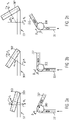
- Figures 3a to 3c show different relative arrangements of the first element 301 and the second element 302 to one another as well as associated representations of the upstream transport device 331 and the downstream transport device 332 and the angle enclosed by them.
- FIG 3a an embodiment is shown in which the included angle ⁇ 1 between the axes of rotation R 1 and R 2 is small, but is for example a few degrees such as 10° or 20°.
- the first element 301 and the second element 302 enclose a comparatively large area 303 in such a way that a product cannot leave this area in the radial direction.
- the angle ⁇ 2 is greater than the angle ⁇ 1 .
- the angle ⁇ 2 can be selected here so that the angle between the feed direction in the first transport device 331 and the discharge direction in the transport device 332 is exactly 90°. Such configurations can be particularly preferred since changing the direction of movement of products by 90° can be advantageous in many applications.
- the angle ⁇ 3 between the axis of rotation R 1 and the axis of rotation R 2 is greater than the angle ⁇ 2 .
- the angle ⁇ 3 enclosed by the transport directions is larger than the angle ⁇ 2 and also larger than the angle ⁇ 1 , so that comparatively little deflection of products is achieved. While such a deflection could still be implemented in a practicable manner, for example by V-shaped conveyor belts, the deflection by the angle ⁇ 3 can be implemented in a comparatively small spatial area by using a deflection device according to this embodiment, which leads to savings in the transport routes of the products can.
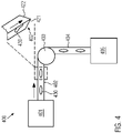
- FIG 4 shows an embodiment of a packaging system using the deflection device 403 according to one of the above embodiments.
- the packaging system 400 includes a treatment machine 401 from which products 430 can be transferred to the first transport device 402 upstream of the deflection device 403 .
- the treatment machine 401 is not limited in the type of treatment it performs on products. In particular, however, the treatment machine can be a centrifuge.
- the products After the products have been transferred to the transport device 402, they are transported in the direction of the deflection device 403 in the direction of the arrow shown. In this they are deflected and transferred to the second transport device 404 . From there, they can be fed to a packaging machine or another treatment machine 405, for example.
- the first transport device 402 is configured as a V-shaped transport belt 402 .
- This V-shaped conveyor belt comprises two conveyor belts 421, 422 which are arranged at an angle to one another so that they enclose a trough in which the products 430 can be transported.
- the angle can be an acute angle or a 90° angle or an obtuse angle.
- the transport belts 421, 422 can enclose an angle of 90° with one another.
- the second transport device 404 can also include such a V-shaped conveyor belt, or both transport devices 402, 404 can include such a V-shaped conveyor belt.
- transport devices 402, 404 are not limited to exclusively comprising transport belts and/or in particular V-shaped transport belts. Other configurations are also conceivable here, such as slide rails for products.
- the first treatment machine 401, the first transport device 402, the deflection device 403 and the second treatment machine 405 can correspond to the 4 be configured and will not be described again here.
- the second transport device 404 downstream of the deflection device 403 initially comprises a sliding area 541 into which the products are transferred from the deflection device and on which they slide along the second transport direction.
- the surface of this sliding area 541 can consist of or include polished stainless steel, for example.
- the sliding area can also be inclined downwards in the transport direction, for example to prevent products from piling up.
- a compartment belt 542 is arranged downstream of the sliding area 541, which can take over the products one after the other from the sliding area.
- troughs components separated from one another by elevations can be arranged in the compartment belt, with the troughs each being able to accommodate one or more products.
- (pre-)portioning can already take place.
- the compartment belt then transports the products in a third transport direction to the processing machine 405 (corresponding to the direction of the arrow shown).
- the third transport direction preferably encloses an angle with the second transport direction, along which products move in the sliding area.
- the third transport direction can preferably run transversely to the second transport direction or be perpendicular to it.
Landscapes
- Engineering & Computer Science (AREA)
- Mechanical Engineering (AREA)
- Attitude Control For Articles On Conveyors (AREA)
Abstract
Description
- Die vorliegende Erfindung betrifft eine Umlenkeinrichtung für eine Transporteinrichtung zum Transportieren von Produkten nach Anspruch 1, sowie eine Transportstrecke zum Transportieren von Produkten nach Anspruch 10 und eine Verpackungsmaschine zum Verpacken von Produkten nach Anspruch 13 und ein Verfahren zum Verpacken von Produkten nach Anspruch 15.
- Transporteinrichtungen zum Transportieren von Produkten sind aus dem Stand der Technik bekannt. Diese umfassen üblicherweise Transportbänder, um Produkte, die ggf. keine feste Form oder Größe aufweisen (etwa Würste oder andere Lebensmittel) zu transportieren. Die Transportbänder sind dabei üblicherweise als einen oder mehrere angetriebene Riemen umfassend ausgestaltet. Dies erlaubt einen zuverlässigen Transport, erfordert jedoch zumeist, dass der Transport nur in gerader Linie erfolgt. Transportbänder, die eine gekrümmte Form aufweisen und die Produkte somit auf gekrümmten Bahnen transportieren können, sind zumeist teuer und erfordern aufgrund des erzielbaren Krümmungsradius viel Platz.
- Für die Konstruktion von Produktionsanlagen bewirkt dies Einschränkungen hinsichtlich der räumlichen Anordnung von Behandlungsmaschinen für die Produkte.
- Ausgehend vom bekannten Stand der Technik besteht die zu lösende technische Aufgabe somit darin, eine Umlenkeinrichtung für eine Transporteinrichtung zum Transportieren von Produkten anzugeben, mit der ein zuverlässigen Umlenken von Produkten von einer ersten in eine zweite Transportrichtung bewirkt und gleichzeitig Platz eingespart werden kann.
- Diese Aufgabe wird durch die Umlenkeinrichtung für eine Transporteinrichtung zum Transportieren von Produkten gemäß Anspruch 1, die Transportstrecke zum Transportieren von Produkten nach Anspruch 10, sowie die Verpackungsmaschine zum Verpacken von Produkten nach Anspruch 13 und das Verfahren zum Verpacken von Produkten nach Anspruch 15 gelöst. Vorteilhafte Weiterbildungen der Erfindung sind in den Unteransprüchen erfasst.
- Die erfindungsgemäße Umlenkeinrichtung für eine Transporteinrichtung zum Transportieren von Produkten, umfasst ein erstes, um eine erste Drehachse drehbar gelagertes Element und ein zweites, um eine zweite Drehachse drehbar gelagertes Element, wobei die Drehachsen miteinander einen Winkel einschließen und das erste und das zweite Element in einem Bereich überlappen, sodass das erste und das zweite Element einen Umlenkbereich einschließen, wobei ein dem Umlenkbereich zugeführtes Produkt in dem Umlenkbereich durch Drehung des ersten und zweiten Elements umgelenkt werden kann und nach Passieren des Umlenkbereichs aufgrund der Massenträgheit die Umlenkeinrichtung verlassen kann.
- Der Umlenkbereich ist hier als ein Bereich zu verstehen, in dem ein Umlenken der Produkte erfolgt, wobei sie von einer ersten Bewegungsrichtung (oder ersten Transportrichtung) aufgrund der Wechselwirkung mit wenigstens einem von dem ersten oder zweiten Element in eine zweite Bewegungsrichtung (oder zweite Transportrichtung), die einen Winkel mit der ersten Bewegungsrichtung einschließt, umgelenkt werden. Dies wird dadurch erreicht, dass die Produkte, während sie von dem ersten und/oder zweiten Element zumindest im Umlenkbereich zu einer der Drehung dieser Elemente folgenden Bewegung veranlasst werden, den Umlenkbereich nicht aufgrund ihrer Massenträgheit verlassen können, da der Umlenkbereich von dem ersten und dem zweiten Element aufgrund ihres Überlapps in diesem Bereich so eingeschlossen ist, dass Produkte den Umlenkbereich nicht verlassen können. Dadurch kann die bei der Bewegung entlang des Umlenkbereichs auf die Produkte einwirkende Zentripetalkraft ein Umlenken bewirken. Außerhalb und stromab des Umlenkbereichs überlappen dann das erste und zweite Element nicht mehr, sodass die Produkte aufgrund ihrer Massenträgheit der Drehung des ersten und zweiten Elements nicht mehr folgen und die Umlenkeinrichtung verlassen können.
- Die Größe des Umlenkbereichs und damit auch der Umlenkwinkel zwischen der ersten Bewegungsrichtung und der zweiten Bewegungsrichtung der Produkte kann durch die Geometrie des ersten und zweiten Elements und/oder den zwischen den Drehachsen des ersten und zweiten Elements eingeschlossenen Winkel bestimmt sein.
- Insbesondere schneiden sich die erste Drehachse und die zweite Drehachse (oder gedachte Verlängerungen dieser) in einem Punkt.
- Mit dieser Umlenkeinrichtung kann ein zuverlässiges Umlenken von Produkten auf kleinem Raum realisiert werden, da auch bei hohen Transportgeschwindigkeiten und kleinem Abstand der Produkte zur Drehachse auf die Produkte einwirkende Kräfte kein Verlassen des Umlenkbereichs bewirken können. Hiermit kann zum einen Platz und zum anderen vorteilhaft auch Kosten für Transporteinrichtungen eingespart werden.
- Es kann vorgesehen sein, dass das erste Element kreisscheibenförmig ist und das zweite Element eine innere, kegelstumpfförmige Oberfläche umfasst, wobei das erste Element in dem Umlenkbereich in die kegelstumpfförmige Oberfläche eingreift.
- Die kegelstumpfförmige Oberfläche muss hier nicht exakt der Form eines Kegelstumpfs entsprechen. So kann die Seitenfläche des Kegelstumpfs auch Wölbungen aufweisen oder mit der Grundfläche und/oder der Deckfläche keine Kanten bilden, sondern stetig in diese übergehen (etwa durch Kreissegmente anstelle der Kanten). Beispielsweise kann die Seitenfläche und/oder die Deckfläche und/oder die Grundfläche als eine Fläche ausgestaltet sein, die im Querschnitt parallel zur Symmetrieachse des Kegelstumpfes einen oder mehrere konkav gekrümmte und/oder konvex gekrümmte Abschnitte oder Elemente umfasst.
- Das kreisscheibenförmige Element kann insbesondere so ausgestaltet sein, dass sein Durchmesser größer ist als die Höhe der Kreisscheibe. Beispielsweise kann der Durchmesser des kreisscheibenförmigen ersten Elements fünfmal größer sein als dessen Höhe. Ein kreisscheibenförmiges Element soll hier nicht nur solche Realisierungen umfassen, die keine innerhalb der Kreisscheibe liegende Öffnung umfassen. Umfasst sind auch Elemente, die etwa zum Hindurchführen einer Drehachse eine zentrale Öffnung aufweisen und/oder zusätzliche Öffnungen im Bereich der Kreisscheibe besitzen, um etwa deren Gewicht zu reduzieren. Auch eine Ausgestaltung exakt entsprechend einer Kreisscheibe ist hier nicht zwingend. So kann das kreisscheibenförmige Element auch Unregelmäßigkeiten auf seiner Oberfläche aufweisen, um etwa die Reibung zwischen er Oberfläche und einem Produkt zu erhöhen. Auch andere Abweichungen von der exakten Form einer Kreisscheibe sind hier denkbar, solang die grundsätzliche, die Form des ersten Elements charakterisierende Grundstruktur die einer Kreisscheibe oder einer Kreisscheibe ähnliche Form ist. Das kreisscheibenförmige erste Element kann an seiner Seitenfläche auch eine umlaufende Einkerbung oder Nut umfassen, in der Produkte transportiert werden können, wobei dann das zweite Element bevorzugt diese Nut umgreifen kann, sodass ein Umlenkbereich eingeschlossen wird.
- Die kegelstumpfförmige innere Oberfläche des zweiten Elements kann bevorzugt so gebildet sein, dass der große und kleine Durchmesser des Kegelstumpfes größer sind als die Höhe des die innere Oberfläche bildenden Kegelstumpfes. Beispielsweise kann auch hier gelten, dass zumindest der größere Durchmesser oder sowohl der größere als auch der kleinere Durchmesser wenigstens fünfmal größer sind als die Höhe des Kegelstumpfes. Durch die Ausgestaltung des zweiten Elements mit einer inneren Oberfläche, die einen Kegelstumpf darstellt, kann ein zuverlässiges Einschließen des ersten Elements in Form einer Kreisscheibe realisiert werden, so dass Produkte den Umlenkbereich nicht unbeabsichtigt verlassen können und gleichzeitig eine zuverlässige Bewegung der Produkte durch den Umlenkbereich möglich ist.
- Weiterhin kann vorgesehen sein, dass das erste Element zwei zueinander entlang der ersten Drehachse beabstandete, konzentrisch angeordnete, um die erste Drehachse drehbar gelagerte, kreisscheibenförmige Segmente umfasst, wobei ein Produkt zwischen den Segmenten aufgenommen und durch die Umlenkeinrichtung transportiert werden kann und wobei die kegelstumpfförmige Oberfläche des zweiten Elements die beiden Segmente im Umlenkbereich umschließt. Die zwei zueinander beabstandeten kreisscheibenförmigen Segmente müssen nicht zwingend separate Segmente sein. Sie können auch, etwa durch die gemeinsame Drehachse oder ein anderes Verbindungselement, miteinander verbunden sein. So kann das erste Element beispielsweise als ein Zylinder mit sich entlang der Deckfläche und entlang der Grundfläche des Zylinders erstreckenden kreisscheibenförmigen Segmenten (etwa im Sinne eines Elements mit Doppel-T-Querschnitt) ausgebildet sein.
- Der Abstand der kreisscheibenförmigen Segmente kann insbesondere so gewählt sein, dass Produkte zwischen den kreisscheibenförmigen Segmenten transportiert werden können. In Verbindung mit der Ausgestaltung des zweiten Elements kann so ein zuverlässiger Transport von Produkten sichergestellt werden.
- In einer Ausführungsform ist vorgesehen, dass ein Winkel zwischen der ersten Drehachse und einer Seitenfläche der inneren, kegelstumpfförmigen Oberfläche des zweiten Elements in zumindest einem Teilbereich des Umlenkbereichs zwischen 0° und 20°, bevorzugt zwischen 0° und 5° beträgt. Hierdurch wird ein Verkanten von Produkten etwa in einem Kontaktbereich oder in dem Überlappbereich zwischen dem ersten Element und dem zweiten Element möglichst vermieden, so dass auch bei hohen Rotationsgeschwindigkeiten ein zuverlässiger Transport von Produkten möglich ist.
- In einer Ausführungsform wird das erste Element durch eine erste Antriebseinrichtung zur Drehung um die erste Drehachse angetrieben und das zweite Element wird durch eine von der ersten Antriebseinrichtung unabhängige, zweite Antriebseinrichtung zur Drehung um die zweite Drehachse angetrieben. Unabhängige Antriebe können so auch bei der vorliegenden Verkippung der Drehachsen zuverlässig die Bewegung des ersten Elements und des zweiten Elements realisieren. Außerdem kann so eine Abstimmung der Winkelgeschwindigkeiten des ersten Elements und des zweiten Elements zuverlässig erfolgen.
- Alternativ kann vorgesehen sein, dass das erste Element und das zweite Element durch eine gemeinsame Antriebseinrichtung zur Drehung um die ersten und die zweite Drehachse angetrieben werden. Dies kann die Komplexität der Dreheinrichtung reduzieren.
- Insbesondere kann vorgesehen sein, dass die erste Antriebseinrichtung und die zweite Antriebseinrichtung das erste Element und das zweite Element mit gleicher Drehzahl antreiben können. Durch die gleiche Drehzahl wird sichergestellt, dass die mit der Umlenkeinrichtung transportierten Produkte keine oder nur geringe unerwünschten Drehmomente erfahren und dadurch etwa Fehlstellungen beim Transport durch die Umlenkeinrichtung einnehmen.
- Es kann ferner vorgesehen sein, dass das erste Element und/oder das zweite Element eine mit Produkt in Kontakt kommende Oberfläche aus Edelstahl umfassen. Diese Ausgestaltung ist konstruktiv einfacher für die Verwendung von zwei unabhängigen Antriebseinrichtungen und kann so die Komplexität der Umlenkeinrichtung und ihre Fehleranfälligkeit vorteilhaft reduzieren.
- In einer Ausführungsform ist vorgesehen, dass das erste Element und/oder das zweite Element eine mit Produkt in Kontakt kommende Oberfläche aus Edelstahl umfassen. Verunreinigungen oder unbeabsichtigte Kontaminationen der Produkte können so vermieden werden.
- Es kann weiterhin vorgesehen sein, dass der von dem ersten Element und dem zweiten Element eingeschlossene Umlenkbereich so ausgestaltet ist, dass ein Produkt, das in den Umlenkbereich entlang einer Zuführrichtung eintritt, den Umlenkbereich in einer Abführrichtung verlässt, wobei ein Winkel zwischen der Zuführrichtung und der Abführrichtung zwischen 45° und 135°, oder zwischen 60° und 120°, oder zwischen 85° und 95° beträgt.
- Der Winkel zwischen der Zuführrichtung und der Abführrichtung kann dabei durch den Winkel, den die Drehachsen des ersten Elements und des zweiten Elements miteinander einschließen, vorteilhaft eingestellt werden. Je kleiner dieser Winkel ist, desto größer ist der Winkel zwischen der Zuführrichtung und der Abführrichtung. Dieser Winkel kann auch variabel einstellbar sein, so dass dieselbe Umlenkeinrichtung auch in verschiedenen Ausgestaltungen und/oder Anordnungen von Transporteinrichtungen zum Einsatz kommen kann und der entsprechende Winkel zwischen der Abführrichtung und der Zuführrichtung je nach Notwendigkeit eingestellt werden kann.
- Erfindungsgemäß kann weiterhin eine Transportstrecke zum Transportieren von Produkten vorgesehen sein, wobei die Transportstrecke eine erste Transporteinrichtung zum Transportieren von Produkten entlang einer ersten Transportrichtung, eine zweite Transporteinrichtung zum Transportieren von Produkten entlang einer zweiten Transportrichtung und eine zwischen der ersten und der zweiten Transporteinrichtung angeordnete Umlenkeinrichtung nach einer der vorangegangenen Ausführungsformen umfasst, wobei die erste Transporteinrichtung Produkte der Umlenkeinrichtung zuführen kann und die Umlenkeinrichtung Produkte von der ersten Transportrichtung in die zweite Transportrichtung umlenken und der zweiten Transporteinrichtung zuführen kann. Diese Transportstrecke kann kompakter ausgeführt werden, so dass Platz in der Produktionsanlage eingespart werden kann.
- Dabei kann vorgesehen sein, dass die erste und/oder die zweite Transporteinrichtung ein V-förmiges Transportband umfassen. V-förmige Transportbänder werden üblicherweise für Produkte verwendet, die keine fest vorgegebene Form oder zumindest nicht alle dieselbe Form aufweisen und ggf. in ihrer Form flexibel sind, wie etwa Würste. Mit dieser Ausführungsform wird ein zuverlässiger Transport zu und/oder von der Umlenkeinrichtung weg bewirkt.
- In einer weiteren Ausführungsform kann vorgesehen sein, dass die zweite Transporteinrichtung einen sich entlang der zweiten Transportrichtung erstreckenden Gleitbereich zum Aufnehmen von Produkten aus der Umlenkeinrichtung und ein Fächerband stromab des Gleitbereichs umfasst, wobei Produkte von dem Gleitbereich in das Fächerband gelangen und in dem Fächerband entlang einer dritten Transportrichtung transportiert werden können. In dem Fächerband können die Produkte beispielsweise in geeignete Aufnahmemulden des Fächerbandes abgelegt und dann weiter transportiert werden. Die dritte Transportrichtung kann mit der zweiten Transportrichtung einen Winkel ungleich Null einschließen, insbesondere quer zur zweiten Transportrichtung verlaufen.
- Erfindungsgemäß ist weiterhin eine Verpackungsanlange zum Verpacken von Produkten, wobei die Verpackungsanlage eine Behandlungsmaschine für Produkte und eine Verpackungsmaschine zum Verpacken von Produkten und eine Transportstrecke nach einer der vorangegangenen Ausführungsformen stromab der Behandlungsmaschine und stromauf der Verpackungsmaschine umfasst. Richtungen stromab sind dabei in Richtung der Transportrichtung der Produkte, Richtungen stromauf entsprechend entgegen der Transportrichtung zu verstehen. Diese Ausführungsform realisiert eine Verpackungsanlage mit reduziertem Platzbedarf für die Transportstrecken zwischen benachbarten Maschinen, insbesondere der Behandlungsmaschine und der Verpackungsmaschine.
- Es kann vorgesehen sein, dass die Behandlungsmaschine eine Zentrifuge ist oder diese umfasst. Zentrifugen kommen hier etwa zum Vereinzeln von Produkten wie Würsten in Betracht. Mit dieser Ausgestaltung wird die Verpackungsanlage zur speziellen Verwendung in der Lebensmittelindustrie ausgelegt.
- Erfindungsgemäß ist weiterhin ein Verfahren zum Transportieren von Produkten, wobei die Produkte von einer ersten Transportrichtung in eine zweite Transportrichtung mittels einer Umlenkeinrichtung nach einer der vorangegangenen Ausführungsformen umgelenkt werden. Dieses Verfahren realisiert einen effektiven Transport von Produkten mit verkürzten Transportwegen.
- Kurze Beschreibung der Figuren
- Fig. 1
- zeigt eine schematische Ansicht einer Umlenkeinrichtung gemäß einer Ausführungsform in Verbindung mit Transporteinrichtungen;
- Fig. 2a u. 2b
- zeigen eine Draufsicht und eine Seitenansicht einer Umlenkeinrichtung gemäß einer Ausführungsform;
- Fig. 3a - 3c
- zeigen verschiedene relative Anordnungen des ersten Elements und des zweiten Elements zueinander gemäß einer Ausführungsform;
- Fig. 4
- zeigt eine Ausführungsform einer Verpackungsanlage.;
- Fig. 5
- zeigt eine zur
Fig. 4 alternative Ausführungsform einer Verpackungsanlage. -
Fig. 1 zeigt eine Umlenkeinrichtung 100 gemäß einer Ausführungsform in Verbindung mit einer der Umlenkeinrichtung in Transportrichtung stromaufwärts angeordneten ersten Transportreinrichtung 131 sowie einer stromabwärts der Umlenkeinrichtung 100 angeordneten zweiten Transporteinrichtung 132. Diese Einrichtungen 100, 131 und 132 können gemeinsam als transportstrecke angesehen werden. Sämtliche in Bezug auf die Umlenkeinrichtung im Folgenden genannten Ausführungsformen sind auch auf eine entsprechende Transportstrecke anwendbar. - Die Umlenkeinrichtung 100 gemäß Ausführungsformen der Erfindung ist dazu ausgestaltet und angeordnet, Produkte 130, die ihr etwa aus der ersten Transporteinrichtung 131 zugeführt werden, in ihrer Bewegungsrichtung umzulenken und der zweiten Transporteinrichtung 132, deren Transportrichtung sich von der Transportrichtung der ersten Transporteinrichtung 131 unterscheiden kann, zuzuführen.
- Die Transporteinrichtungen 131, 132 können als Transportbänder ausgebildet sein. Insbesondere kann eine der Transporteinrichtungen 131, 132 oder auch beide als V-förmiges Transportband ausgebildet sein, das zwei in einem spitzen Winkel zueinander angeordnete Transportbänder umfasst, wobei in der so gebildeten Mulde zwischen diesen Transportbändern Produkte 130 transportiert werden können. Bei den Produkten 130 kann, muss es sich jedoch nicht, um Lebensmittel wie beispielweise Würste handeln. Auch Verpackungen (leer oder befüllt) können transportiert werden. Hinsichtlich der mit der Umlenkeinrichtung und/oder den Transporteinrichtungen beförderten Produkten ist die Erfindung jedoch grundsätzlich nicht beschränkt.
- Um die entlang der ersten Transportrichtung in der Transporteinrichtung 131 transportierten Produkte 130 in ihrer Bewegungsrichtung umzulenken, umfasst die Umlenkeinrichtung 100 ein erstes Element 101, das um eine Drehachse R1 drehbar gelagert ist. Die Drehrichtung ist dabei bevorzugt so gewählt, dass die Produkte ihre Bewegung bei der Übergabe von der Transporteinrichtung 131 in die Umlenkeinrichtung 100 fortsetzen.
- Weiterhin umfasst die Umlenkeinrichtung 100 ein zweites, um eine zweite Drehachse R2 drehbares Element, das mit dem ersten Element in einem Bereich überlappt, so dass in diesem Bereich transportierte Produkte 130 nicht aufgrund ihrer Massenträgheit aus dem Bereich hinaus gelangen können. Dieser Bereich wird auch als Umlenkbereich bezeichnet.
- Die Produkte 130 folgen in dem Umlenkbereich der Drehung des ersten Elements 101 bzw. des zweiten Elements 102 um die jeweilige Drehachse, da sie aufgrund der auf sie einwirkenden Zentripetalkraft auf eine Kreisbahn gezwungen werden.
- In Drehrichtung des ersten Elements und des zweiten Elements nach dem Umlenkbereich überlappen das erste Element 101 und das zweite Element 102 nicht mehr, so dass die Produkte aufgrund ihrer Massenträgheit den Umlenkbereich und insbesondere die Umlenkeinrichtung verlassen können und in die Transporteinrichtung 132 gelangen.
- Dabei kann insbesondere die Größe des Umlenkbereichs so gewählt sein, dass Produkte vor dem Umlenkbereich dem Element 101 übergeben werden können, dann in den Umlenkbereich eindringen und umgelenkt werden um anschließend den Umlenkbereich in einer Richtung zu verlassen, die mit der Transportrichtung der Transporteinrichtung 132 zusammenfällt. Besonders bevorzugt kann eine Tangente an die äußere Oberfläche das erste Elements 101 am Ende des Umlenkbereichs parallel zu der Transportrichtung der Transporteinrichtung 132 sein. Da die Tangente parallel oder gleich der Bewegungsrichtung der Produkte aufgrund ihrer Massenträgheit ist, wird so sichergestellt, dass die Produkte die Umlenkeinrichtung mit einer Bewegungsrichtung verlassen, die der Transportrichtung der nachgeordneten oder stromab angeordneten Transporteinrichtung 132 entspricht.
- Um einen Umlenkbereich zu realisieren, der sich nicht um die gesamte Umlenkeinrichtung erstreckt, ist vorgesehen, dass die erste Rotationsachse R1 des ersten Elements 101 und die zweite Rotationsachse R2 des zweiten Elements 102 einen Winkel α miteinander einschließen und insbesondere nicht parallel zueinander sind.
- Bei einer im Wesentlichen kreisscheibenförmigen Ausgestaltung des ersten Elements 101 und einer im Wesentlichen zylindrischen Ausgestaltung des zweiten Elements 102, das bevorzugt im Umlenkbereich um das erste Element 101 umgreift, bewirkt dies, dass der Umlenkbereich sich nur über einen Teilbereich des Umfangs des ersten Elements und des zweiten Elements erstreckt. Die Größe des Umlenkbereichs hängt dabei von dem von der ersten Drehachse R1 und der zweiten Drehachse R2 eingeschlossenen Winkel ab.
- Um die Drehung des ersten Elements 101 um die Drehachse R1 und des zweiten Elements 102 um die Drehachse R2 zu realisieren, kann jedem der Elemente eine separate Antriebseinrichtung zugeordnet sein. In der Ansicht der
Fig. 1 ist dem Element 101 die Antriebseinrichtung 111 zugeordnet und dem Element 102 ist die Antriebseinrichtung 112 zugeordnet. Bei diesen Antriebseinrichtungen kann es sich um voneinander unabhängig betätigbare und/oder ansteuerbare Elektromotoren handeln. Insbesondere können Servomotoren zum Einsatz kommen. - Dabei kann zweckmäßig vorgesehen sein, dass die Antriebseinrichtungen 111, 112 zwar unabhängig voneinander ansteuerbar sind, aber so angesteuert werden können, dass die Drehzahl des ersten Elements und die Drehzahl des zweiten Elements übereinstimmen. Besonders bevorzugt kann vorgesehen sein, dass die Winkelgeschwindigkeiten des ersten Elements und des zweiten Elements gleich sind. Alternativ oder zusätzlich kann vorgesehen sein, dass die Tangentialgeschwindigkeiten des ersten Elements und des zweiten Elements in einem Bereich, in dem zwischen dem ersten Element und dem zweiten Element ein Produkt transportiert wird, das dabei mit dem ersten Element und dem zweiten Element in Berührung kommt, im Wesentlichen gleich sind. Dadurch wird gewährleistet, dass Produkte, die mit dem ersten Element 101 und dem zweiten Element 102 in Berührung kommen, keine unterschiedlichen auf sie einwirkenden Drehmomente erfahren, was zu unerwünschter Bewegung der Produkte führen könnte.
-
Fig. 2a und 2b zeigen eine Draufsicht und eine Seitenansicht der Umlenkeinrichtung ausFig. 1 gemäß einer Ausführungsform. - In
Fig. 2a ist der Bereich 240 dargestellt, in dem das erste Element 201 und das zweite Element 202 derart überlappen, dass ein Produkt bei einer Entlangbewegung in dem so gebildeten Überlappbereich, der auch als Umlenkbereich 240 bezeichnet wird, diesen Bereich nicht in radialer Richtung (gesehen von der Rotationsachse R1 oder der Rotationsachse R2 aus) verlassen kann, da eine solche radiale Bewegung eines Produkts durch den Überlapp des ersten und des zweiten Elements zumindest in radialer Richtung blockiert wird. - In Transportrichtung der Produkte durch die Umlenkeinrichtung 200 befindet sich stromauf und bevorzugt unmittelbar vor dem Umlenkbereich ein Übergabepunkt, an dem die Transporteinrichtung 231 Produkte der Umlenkeinrichtung 200 zuführen kann. Diese können etwa mittels hoher Transportgeschwindigkeit in einem Transportband der Transporteinrichtung 231 in den Umlenkbereich geschossen werden. Da ein Verlassen des Umlenkbereichs aufgrund des Überlapps des ersten und zweiten Elements nicht möglich ist, kann es hierdurch nicht zu einem Entweichen der Produkte kommen.
- Bevorzugt ist vorgesehen, dass die Transportgeschwindigkeit der Produkte in der ersten Transporteinrichtung 231 der Tangentialgeschwindigkeit der Produkte im Umlenkbereich der Umlenkeinrichtung 200 entspricht und auch die Transportgeschwindigkeit der Produkte in der nachfolgenden Transporteinrichtung 232 dieselbe Geschwindigkeit aufweist. Dies ist jedoch nicht zwingend. Bevorzugt kann die Transportgeschwindigkeit in der stromab nachfolgenden Einrichtung jeweils größer sein als in der vorherigen, sodass kein Abbremsen und damit eventuelles Kollidieren von Produkten erfolgt.
- In der
Fig. 2b ist eine Seitenansicht der Umlenkeinrichtung ohne die weiteren Transporteinrichtungen aus derFig. 2a gezeigt. In der hier dargestellten Ausführungsform umfasst das erste Element 201 zwei zueinander beabstandete kreisförmige bzw. kreisscheibenförmige Segmente 211, 212, zwischen denen, wie hier gezeigt, ein Produkt 230 aufgenommen werden kann, um durch die Umlenkeinrichtung transportiert zu werden. Diese Ausgestaltung ist nicht zwingend. Es kann auch vorgesehen sein, dass das erste Element 201 lediglich als ein kreisscheibenförmiges Segment umfassend ausgebildet ist. Zwar sind die kreisscheibenförmigen Segmente bevorzugt beabstandet. Dies soll aber auch umfassen, dass die kreisscheibenförmigen Segmente physisch miteinander verbunden sein können, etwa durch ein sich um die Drehachse erstreckendes Verbindungselement oder die Drehachse selbst. - Die zwei Kreissegmente 211 und 212 sind zueinander konzentrisch mit einem Abstand zueinander angeordnet und um die gemeinsame Drehachse R1 drehbar gelagert. Der Antrieb der beiden Kreisscheibensegmente kann etwa über die gemeinsamen Antriebseinrichtung 111, wie sie in
Fig. 1 gezeigt ist, bewirkt werden. Alternativ ist es auch möglich, beide Segmente 211, 212 unabhängig voneinander mit separaten Antriebseinrichtungen anzutreiben. - In der hier dargestellten Ausführungsform besitzen die beiden Segmente 211, 212 denselben Durchmesser. Dies ist nicht zwingend der Fall. Eines der Segmente kann auch einen kleineren Durchmesser als das andere Segment aufweisen. Insbesondere im Hinblick auf die verkippte Stellung des zweiten Elements 202 kann es beispielsweise zweckmäßig sein, wenn der Durchmesser des unteren in der
Fig. 2b dargestellten Segments 211 kleiner ist als der des oberen Segments 212, so dass bei einer Ausgestaltung der inneren Oberfläche des zweiten Elements 202 als Kegelstumpf oder als Kegel (wie im Folgenden noch erläutert) ein ungehindertes Eingreifen bzw. Umschließen des Umlenkbereichs bewirkt werden kann. - In der
Fig. 2b ist mit gestrichelten Linien der Umlenkbereich 240 gezeigt. Dies ist bevorzugt als der Bereich zu verstehen, in dem Produkte den von dem ersten Element 201 und dem zweiten Element 202 eingeschlossenen Bereich zumindest nicht in radialer Richtung verlassen können. Dieser Bereich wird dadurch gebildet, dass das zweite Element 202 das erste Element 201 von außen umgreift. Dies gilt unabhängig davon, ob das erste Element 201 als zwei kreisscheibenförmige Segmente 211, 212 umfassend ausgebildet ist oder als lediglich ein solches Segment oder eine andere Ausgestaltung umfassend realisiert ist. Insbesondere wird der Umlenkbereich 240 dadurch realisiert, dass sich das erste Element 201 im Umlenkbereich in den Innenraum des zweiten Elements 202 hinein erstreckt. - Zu diesem Zweck kann das zweite Element 202 etwa als im Wesentlichen hohler Zylinder ausgestaltet sein. Der hohle Zylinder besitzt eine innere Oberfläche 221. In einigen Ausführungsformen ist vorgesehen, dass diese als Oberfläche eines Kegelstumpfes, der nach unten hin (zu seiner Grundfläche mit größerem Durchmesser) geöffnet ausgestaltet ist, realisiert wird. Dies kann bevorzugt so realisiert werden, dass die Symmetrieachse dieses Kegelstumpfes mit der Rotationsachse R2 zusammenfällt. Der Anstellwinkel der Seitenfläche der inneren, kegelstumpfförmigen Oberfläche des zweiten Elements 202 kann so gewählt sein, dass die Seitenfläche im Umlenkbereich zumindest teilweise parallel zur Rotationsachse R1 verläuft oder mit dieser einen stumpfen Winkel oder einen spitzen Winkel einschließt. Dabei kann ein stumpfer Winkel, der größer als 90° aber kleiner als 180° ist, bevorzugt sein, da so ein unbeabsichtigtes Einklemmen von Produkten im Umlenkbereich vermieden wird.
- Alternativ dazu kann die innere Oberfläche des zweiten Elements 202 auch als Zylinder oder Zylinderfläche ausgestaltet sein. Die Mantelfläche dieses Zylinders erstreckt sich dann parallel zur Rotationsachse R2, so dass, wenn die Rotationsachse R2 mit der Rotationsachse R1 des ersten Elements 201 den hier dargestellten Winkel α einschließt, die innere Oberfläche des zweiten Elements 202 mit dem ersten Element 201 einen Winkel von 90° + α einschließt, was in jedem Fall ein stumpfer Winkel ist, sofern α ein spitzer Winkel ist.
- Wie bereits oben beschrieben, kann, wenn das erste Element 201 als zwei kreisscheibenförmige Segmente 211, 212 umfassend ausgebildet ist, vorgesehen sein, dass diese Segmente unterschiedliche Durchmesser besitzen. In der hier dargestellten Ausführungsform, in der die innere Oberfläche des zweiten Elements 202 als kegelstumpfförmig ausgebildet ist, und sich dessen Mantelfläche parallel zur Rotationsachse R1 erstreckt, ist es bevorzugt, wenn die Segmente 211, 212 denselben Durchmesser aufweisen, da diese dann zumindest in dem Umlenkbereich 240, in dem sich die innere Oberfläche des zweiten Elements und das erste Element am nächsten sind, ein möglichst vollständiges Abschließen bzw. nach oben hin und nach unten hin vollständiges Umschließen von Produkten 130 in dem Umlenkbereich bewirkt werden kann.
- Alternativ kann auch vorgesehen sein, dass der Durchmesser des oberen Segments 212 von dem des unteren Segments 211 verschieden ist, was insbesondere bei Ausgestaltung der inneren Oberfläche des zweiten Elements 202 als Zylinderfläche sinnvoll sein kann. In einem solchen Fall kann, um einen möglichst vollständigen Abschluss bzw. eine vollständige Begrenzung des Bereichs 240 durch die zwei Segmente 211, 212 und das zweite Element 202 zu realisieren, der Durchmesser des oberen Segments 212 um einen Betrag

- Während die äußere Gestalt des zweiten Elements 202 der
Fig. 2b als Zylinder beschrieben wurde, ist dies nicht zwingend der Fall. Auch die äußere Oberfläche des zweiten Elements 202 kann beispielsweise als Kegelstumpf oder anders geformtes Element ausgestaltet sein, solange die innere Oberfläche so ausgestaltet ist, dass sie mit dem ersten Element 201 zusammen den Umlenkbereich 240 einschließen kann, um hierin Produkte in ihrer Bewegungsrichtung umzulenken. - Wie in der
Fig. 2b schematisch dargestellt, treten die Produkte 130 zumindest mit einem Teil des ersten Elements 201 (hier zumindest dem unteren Segment 211) und einem Teil der inneren Oberfläche des zweiten Elements 202 in Kontakt. Bei der Bewegung durch den Umlenkbereich werden die Produkte aufgrund der in ihrem Inertialsystem wirkenden Zentrifugalkraft bzw. aufgrund ihrer eigenen Massenträgheit in radialer Richtung von der Rotationsachse R1 bewegt. Diese Bewegung erfolgt soweit, bis die Produkte in dem Umlenkbereich von dem ersten Element und/oder dem zweiten Element an einer weiteren Bewegung in radialer Richtung gehindert werden. - Da es sich bei den Produkten um Lebensmittel handeln kann, kann es vorteilhaft sein, wenn die mit dem Produkt in Kontakt tretende Fläche des ersten Elements und des zweiten Elements eine von Bakterien und/oder Verunreinigungen nur schwierig zu benetzende Oberfläche aufweist. Beispielsweise kann die Oberfläche aus Edelstahl bestehen oder diese umfassen. Auch antibakteriell wirkende Kunststoffe oder Beschichtungen daraus sind für die innere Oberfläche des zweiten Elements 202 und/oder für die mit Produkten in Kontakt tretende Oberfläche des ersten Elements 201 denkbar. Es kann auch vorgesehen sein, dass die gesamte Oberfläche des ersten Elements und des zweiten Elements, umfassend sowohl die innere als auch die äußere Oberfläche, aus Edelstahl besteht oder damit beschichtet ist.
- Die
Fig. 3a bis 3c zeigen verschiedene relative Anordnungen des ersten Elements 301 und des zweiten Elements 302 zueinander sowie dazugehörige Darstellungen der vorgeschalteten Transporteinrichtung 331 und der nachgeschalteten Transporteinrichtung 332 und den von diesen eingeschlossenen Winkel. - Ganz allgemein gilt, dass, je kleiner der Winkel α zwischen den Rotationsachsen R1 und der Rotationsachse R2 ist, desto größer ist der von dem ersten Element und dem zweiten Element eingeschlossene Bereich und damit der Umlenkbereich gemessen als Anteil des Vollkreises. Dies bedeutet, dass auch der zwischen den Transportrichtungen der Transporteinrichtungen 331, 332 eingeschlossene Winkel kleiner ist, je kleiner der Winkel α ist.
- In
Fig. 3a ist eine Ausführungsform gezeigt, in der der zwischen den Rotationsachsen R1 und R2 eingeschlossene Winkel α1 klein ist, aber beispielsweise wenige Grad wie beispielsweise 10° oder 20° beträgt. Dadurch schließen das erste Element 301 und das zweite Element 302 einen vergleichsweise großen Bereich 303 derart ein, dass ein Produkt diesen Bereich in radialer Richtung nicht verlassen kann. - Damit ergibt sich ein Umlenkwinkel β1, der angibt, unter welchem Winkel die Transportrichtung der Transporteinrichtung 331 und die Transportrichtung der Transporteinrichtung 332 stehen. Dieser Winkel ist in
Fig. 3a vergleichsweise klein. Er hängt insbesondere auch von der Größe der Elemente ab. - In
Fig. 3b ist der Winkel α2 größer als der Winkel α1. Der Winkel α2 kann hier so gewählt sein, dass der Winkel zwischen der Zuführrichtung in der ersten Transporteinrichtung 331 und der Abführrichtung in der Transporteinrichtung 332 genau 90° beträgt. Solche Ausgestaltungen können besonders bevorzugt sein, da eine Änderung der Bewegungsrichtung von Produkten um 90° in vielen Anwendungen vorteilhaft sein kann. -
Fig. 3c zeigt eine weitere Ausführungsform, bei der der Winkel α3 zwischen Rotationsachse R1 und Rotationsachse R2 größer ist als der Winkel α2. In diesem Fall ist der von den Transportrichtungen eingeschlossene Winkel β3 größer als der Winkel β2 und auch größer als der Winkel β1, so dass ein vergleichsweise geringes Umlenken von Produkten erzielt wird. Während ein solches Umlenken etwa durch V-förmige Transportbänder noch auf praktikable Weise realisiert werden könnte, kann durch Anwendung einer Umlenkeinrichtung entsprechend dieser Ausführungsform das Umlenken um den Winkel β3 in einem vergleichsweise kleinen Raumbereich realisiert werden, was zu Einsparungen in den Transportwegen der Produkte führen kann. -
Fig. 4 zeigt eine Ausführungsform einer Verpackungsanlage unter Verwendung der Umlenkeinrichtung 403 entsprechend einer der obigen Ausführungsformen. - Die Verpackungsanlage 400 umfasst eine Behandlungsmaschine 401, aus der Produkte 430 in die erste Transporteinrichtung 402 stromaufwärts der Umlenkeinrichtung 403 übergeben werden können. Die Behandlungsmaschine 401 ist hinsichtlich der Art der Behandlung, die sie an Produkten durchführt, nicht beschränkt. Insbesondere kann es sich bei der Behandlungsmaschine jedoch um eine Zentrifuge handeln.
- Nachdem die Produkte in die Transporteinrichtung 402 übergeben wurden, werden diese entsprechend der dargestellten Pfeilrichtung in Richtung der Umlenkeinrichtung 403 transportiert. In dieser werden sie umgelenkt und in die zweite Transporteinrichtung 404 übergeben. Von dieser aus können sie etwa einer Verpackungsmaschine oder einer anderen Behandlungsmaschine 405 zugeführt werden.
- In der in
Fig. 4 dargestellten Ausführungsform ist beispielhaft vorgesehen, dass die erste Transporteinrichtung 402 als V-förmiges Transportband 402 ausgestaltet ist. Dieses V-förmige Transportband umfasst zwei Transportriemen 421, 422, die in einem Winkel zueinander angeordnet sind, so dass sie eine Mulde einschließen, in der die Produkte 430 transportiert werden können. Der Winkel kann ein spitzer Winkel oder ein 90°-Winkel oder auch ein stumpfer Winkel sein. Beispielsweise können die Transportriemen 421, 422 einen Winkel von 90° miteinander einschließen. - Alternativ kann auch die zweite Transporteinrichtung 404 ein solches V-förmiges Transportband umfassen oder beide Transporteinrichtungen 402, 404 können ein solches V-förmiges Transportband umfassen.
- Die Transporteinrichtungen 402, 404 sind jedoch nicht darauf beschränkt, dass sie ausschließlich Transportbänder und/oder im Speziellen V-förmige Transportbänder umfassen. Auch andere Ausgestaltungen sind hier denkbar, wie beispielsweise Gleitschienen für Produkte.
- In der
Fig. 5 ist eine verglichen mit derFig. 4 abgewandelte Ausführungsform dargestellt. Die erste Behandlungsmaschine 401, die erste Transporteinrichtung 402, die Umlenkeinrichtung 403 und die zweite Behandlungsmaschine 405 können entsprechend derFig. 4 ausgestaltet sein und werden hier nicht erneut beschrieben. - In dieser Ausführungsform umfasst die zweite Transporteinrichtung 404 stromab der Umlenkeinrichtung 403 zunächst einen Gleitbereich 541, in den die Produkte von der Umlenkeinrichtung übergeben werden und auf dem sie entlang der zweiten Transportrichtung gleiten. Dazu kann die Oberfläche dieses Gleitbereichs 541 beispielsweise aus poliertem Edelstahl bestehen oder diese umfassen. Der Gleitbereich kann auch in Transportrichtung abwärts geneigt sein, etwa um ein Aufstauen von Produkten zu vermeiden.
- Stromab des Gleitbereichs 541 ist hier ein Fächerband 542 angeordnet, das die Produkte nacheinander aus dem Gleitbereich übernehmen kann. Dazu können in dem Fächerband etwa voneinander durch Erhebungen getrennte Mulden (Fächer) angeordnet sein, wobei die Mulden jeweils ein oder mehrere Produkte aufnehmen können. Hierdurch kann bereits eine (Vor-)Portionierung erfolgen. Das Fächerband transportiert die Produkte in der hier dargestellten Ausführungsform dann in einer dritten Transportrichtung zur Behandlungsmaschine 405 (entsprechend der dargestellten Pfeilrichtung). Die dritte Transportrichtung schließt dabei mit der zweiten Transportrichtung, entlang der sich Produkte im Gleitbereich bewegen, bevorzugt einen Winkel ein. Bevorzugt kann die dritte Transportrichtung quer zur zweiten Transportrichtung verlaufen bzw. senkrecht zu dieser sein.
Claims (15)
- Umlenkeinrichtung (100) für eine Transporteinrichtung zum Transportieren von Produkten (130), wobei die Umlenkeinrichtung ein erstes, um eine erste Drehachse drehbar gelagertes Element (101) und ein zweites, um eine zweite Drehachse drehbar gelagertes Element (102) umfasst, wobei die Drehachsen miteinander einen Winkel einschließen und das erste und das zweite Element in einem Bereich überlappen, sodass das erste und das zweite Element einen Umlenkbereich (240) einschließen, wobei ein dem Umlenkbereich zugeführtes Produkt in dem Umlenkbereich durch Drehung des ersten und zweiten Elements umgelenkt werden kann und nach Passieren des Umlenkbereichs aufgrund der Massenträgheit die Umlenkeinrichtung (100) verlassen kann.
- Umlenkeinrichtung (100) nach Anspruch 1, wobei das erste Element (201) kreisscheibenförmig ist und das zweite Element (202) eine innere, kegelstumpfförmige Oberfläche (221) umfasst, wobei das erste Element in dem Umlenkbereich in die kegelstumpfförmige Oberfläche eingreift.
- Umlenkeinrichtung (100) nach Anspruch 2, wobei das erste Element (201) zwei zueinander entlang der ersten Drehachse beabstandete, konzentrisch angeordnete, um die erste Drehachse drehbar gelagerte, kreisscheibenförmige Segmente (211, 212) umfasst, wobei ein Produkt zwischen den Segmenten aufgenommen und durch die Umlenkeinrichtung transportiert werden kann und wobei die kegelstumpfförmige Oberfläche (221) des zweiten Elements die beiden Segmente im Umlenkbereich (240) umschließt.
- Umlenkeinrichtung (100) nach Anspruch 2 oder 3, wobei ein Winkel zwischen der ersten Drehachse und einer Seitenfläche der inneren, kegelstumpfförmigen Oberfläche (221) des zweiten Elements (202) in zumindest einem Teilbereich des Umlenkbereichs (240) zwischen 0° und 20°, bevorzugt zwischen 0° und 5° beträgt.
- Umlenkeinrichtung (100) nach einem der Ansprüche 1 bis 4, wobei das erste Element (101) durch eine erste Antriebseinrichtung (111) zur Drehung um die erste Drehachse angetrieben wird und das zweite Element (102) durch eine von der ersten Antriebseinrichtung unabhängige, zweite Antriebseinrichtung (121) zur Drehung um die zweite Drehachse angetrieben wird.
- Umlenkeinrichtung (100) nach Anspruch 5, wobei die erste Antriebseinrichtung (111) und die zweite Antriebseinrichtung (121) das erste Element (101) und das zweite Element (102) mit gleicher Drehzahl antreiben können.
- Umlenkeinrichtung (100) nach einem der Ansprüche 1 bis 4, wobei das erste Element (101) und das zweite Element (102) durch eine gemeinsame Antriebseinrichtung zur Drehung um die ersten und die zweite Drehachse angetrieben werden.
- Umlenkeinrichtung (100) nach einem der Ansprüche 1 bis 7, wobei das erste Element (101) und/oder das zweite Element (102) eine mit Produkt (130) in Kontakt kommende Oberfläche aus Edelstahl umfassen.
- Umlenkeinrichtung (100) nach einem der Ansprüche 1 bis 8, wobei der von dem ersten Element (101) und dem zweiten Element (102) eingeschlossene Umlenkbereich (240) so ausgestaltet ist, dass ein Produkt, das in den Umlenkbereich entlang einer Zuführrichtung eintritt, den Umlenkbereich in einer Abführrichtung verlässt, wobei ein Winkel zwischen der Zuführrichtung und der Abführrichtung zwischen 45° und 135°, oder zwischen 60° und 120°, oder zwischen 85° und 95° beträgt.
- Transportstrecke zum Transportieren von Produkten, wobei die Transportstrecke eine erste Transporteinrichtung (131) zum Transportieren von Produkten entlang einer ersten Transportrichtung, eine zweite Transporteinrichtung (132) zum Transportieren von Produkten entlang einer zweiten Transportrichtung und eine zwischen der ersten und der zweiten Transporteinrichtung angeordnete Umlenkeinrichtung (100) nach einem der Ansprüche 1 bis 9 umfasst, wobei die erste Transporteinrichtung (131) Produkte (130) der Umlenkeinrichtung (100) zuführen kann und die Umlenkeinrichtung Produkte von der ersten Transportrichtung in die zweite Transportrichtung umlenken und der zweiten Transporteinrichtung (132) zuführen kann.
- Transportstrecke nach Anspruch 10, wobei die erste und/oder die zweite Transporteinrichtung ein V-förmiges Transportband umfassen.
- Transportstrecke nach Anspruch 10 oder 11, wobei die zweite Transporteinrichtung (404) einen sich entlang der zweiten Transportrichtung erstreckenden Gleitbereich (541) zum Aufnehmen von Produkten aus der Umlenkeinrichtung (403) und ein Fächerband (542) stromab des Gleitbereichs umfasst, wobei Produkte von dem Gleitbereich in das Fächerband gelangen und in dem Fächerband entlang einer dritten Transportrichtung transportiert werden können.
- Verpackungsanlange (400) zum Verpacken von Produkten, wobei die Verpackungsanlage eine Behandlungsmaschine (401) für Produkte und eine Verpackungsmaschine (405) zum Verpacken von Produkten und eine Transportstrecke nach einem der Ansprüche 10 bis 12 stromab der Behandlungsmaschine und stromauf der Verpackungsmaschine umfasst.
- Verpackungsanlage (400) nach Anspruch 13, wobei die Behandlungsmaschine (401) eine Zentrifuge ist oder diese umfasst.
- Verfahren zum Transportieren von Produkten (130), wobei die Produkte von einer ersten Transportrichtung in eine zweite Transportrichtung mittels einer Umlenkeinrichtung (100) nach einem der Ansprüche 1 bis 9 umgelenkt werden.
Applications Claiming Priority (1)
| Application Number | Priority Date | Filing Date | Title |
|---|---|---|---|
| DE102020135131.3A DE102020135131B4 (de) | 2020-12-30 | 2020-12-30 | Umlenkeinrichtung für Produkte |
Publications (2)
| Publication Number | Publication Date |
|---|---|
| EP4023575A1 true EP4023575A1 (de) | 2022-07-06 |
| EP4023575B1 EP4023575B1 (de) | 2024-08-28 |
Family
ID=79020991
Family Applications (1)
| Application Number | Title | Priority Date | Filing Date |
|---|---|---|---|
| EP21217008.8A Active EP4023575B1 (de) | 2020-12-30 | 2021-12-22 | Umlenkeinrichtung für produkte |
Country Status (6)
| Country | Link |
|---|---|
| US (1) | US11603271B2 (de) |
| EP (1) | EP4023575B1 (de) |
| CN (1) | CN114684415B (de) |
| DE (1) | DE102020135131B4 (de) |
| ES (1) | ES2991515T3 (de) |
| PL (1) | PL4023575T3 (de) |
Citations (4)
| Publication number | Priority date | Publication date | Assignee | Title |
|---|---|---|---|---|
| GB1444929A (en) * | 1972-10-27 | 1976-08-04 | Colubra Lamsat Spa | Conveyor system for conveying articles |
| DE2611354A1 (de) * | 1976-03-18 | 1977-09-22 | Uwe Klahn | Vorrichtung zum befoerdern, insbesondere von suesswarenstuecken |
| DE102004060640A1 (de) * | 2004-12-16 | 2006-07-06 | Weber Maschinenbau Gmbh & Co. Kg | Transportvorrichtung |
| US8297434B2 (en) * | 2008-05-20 | 2012-10-30 | Ima Safe S.R.L. | Product conveyor unit |
Family Cites Families (21)
| Publication number | Priority date | Publication date | Assignee | Title |
|---|---|---|---|---|
| US1489926A (en) * | 1923-07-24 | 1924-04-08 | Arthur E Burtchaell | Conveyer |
| US2602531A (en) * | 1950-01-03 | 1952-07-08 | John G Plank | Dividing head for bottle conveyers |
| US3710937A (en) * | 1970-12-18 | 1973-01-16 | Ball Corp | Method and apparatus for transporting glassware |
| IT1036531B (it) * | 1975-01-29 | 1979-10-30 | Gd Spa | Impianto per la produzione di pac chetti di sigarette con alimentazione diretta delle sigarette dalla o dalle macchine che le confezionano confezionatrici alla tramoggia di raggruppamento e di erogazione alla linea d incarto della macchina che le impacchetta impacchettatrice e dispositivo a magazzino di compansazione degli squlibri produttivi fra dette macchine |
| FI69814C (fi) * | 1981-03-24 | 1986-05-26 | Will E C H Gmbh & Co | Anordning foer aendring av transportriktningen hos enskilda foremaol |
| FR2524436B1 (fr) * | 1982-04-02 | 1985-09-27 | Nantaise Biscuiterie | Dispositif regulateur de transfert de produits solides identiques entre des machines amont et aval de vitesses differentes |
| US4564105A (en) * | 1983-12-29 | 1986-01-14 | Lear Siegler, Inc. | Tilted spiral article diverter |
| DE4107293A1 (de) * | 1990-03-10 | 1991-09-12 | Siegmund Kumeth | Foerderstrecke |
| EP0649729B1 (de) * | 1993-09-01 | 2000-01-12 | Steiff Fördertechnik GmbH | Fördervorrichtung mit in einer Bandkurve geführtem Förderband |
| US5439098A (en) * | 1994-01-03 | 1995-08-08 | United Parcel Service Of America, Inc. | Powered belt turn |
| JPH0930623A (ja) * | 1995-07-19 | 1997-02-04 | Atsusato Kitamura | カーブベルト装置およびカーブベルト |
| US5954184A (en) * | 1997-09-12 | 1999-09-21 | Hoppmann Corporation | Apparatus and method for feeding, presenting and/or orienting parts |
| JP4562435B2 (ja) * | 2004-06-23 | 2010-10-13 | 三機工業株式会社 | ホリゾンタルダイバータ |
| JP2006017648A (ja) * | 2004-07-05 | 2006-01-19 | Fuji Photo Film Co Ltd | 測定装置 |
| JP4885472B2 (ja) | 2005-04-13 | 2012-02-29 | 日本特殊陶業株式会社 | ターンテーブル及びそれを用いたターンコンベア並びにコンベア用受け皿 |
| EP2233413B1 (de) * | 2006-08-15 | 2012-06-06 | Sidel Participations, S.A.S. | Verfahren und Vorrichtung zur Überführung von hohlen zylindrischen Gegenständen |
| EP3135593B1 (de) * | 2012-03-23 | 2019-02-20 | C.G. Bretting Manufacturing Company, Inc. | Hochgeschwindigkeits-pack-wrapper |
| US8607959B2 (en) * | 2012-04-16 | 2013-12-17 | The Procter & Gamble Company | Rotational assemblies and methods for transferring discrete articles |
| ITMI20132070A1 (it) * | 2013-12-12 | 2015-06-13 | Bonino S P A Ora Giovanni Bonino S P A | Sistema e metodo per l' orientamento di oggetti |
| GB201405341D0 (en) * | 2014-03-25 | 2014-05-07 | British American Tobacco Co | Feed unit |
| FR3075188A1 (fr) * | 2017-12-19 | 2019-06-21 | C.E.R.M.E.X. Constructions Etudes Et Recherches De Materiels Pour L'emballage D'expedition | Dispositif et procede de positionnement de produits de front ou de cote simultanement a leur convoyage |
-
2020
- 2020-12-30 DE DE102020135131.3A patent/DE102020135131B4/de active Active
-
2021
- 2021-12-22 EP EP21217008.8A patent/EP4023575B1/de active Active
- 2021-12-22 ES ES21217008T patent/ES2991515T3/es active Active
- 2021-12-22 PL PL21217008.8T patent/PL4023575T3/pl unknown
- 2021-12-27 US US17/562,770 patent/US11603271B2/en active Active
- 2021-12-28 CN CN202111624696.1A patent/CN114684415B/zh active Active
Patent Citations (4)
| Publication number | Priority date | Publication date | Assignee | Title |
|---|---|---|---|---|
| GB1444929A (en) * | 1972-10-27 | 1976-08-04 | Colubra Lamsat Spa | Conveyor system for conveying articles |
| DE2611354A1 (de) * | 1976-03-18 | 1977-09-22 | Uwe Klahn | Vorrichtung zum befoerdern, insbesondere von suesswarenstuecken |
| DE102004060640A1 (de) * | 2004-12-16 | 2006-07-06 | Weber Maschinenbau Gmbh & Co. Kg | Transportvorrichtung |
| US8297434B2 (en) * | 2008-05-20 | 2012-10-30 | Ima Safe S.R.L. | Product conveyor unit |
Also Published As
| Publication number | Publication date |
|---|---|
| CN114684415B (zh) | 2024-07-09 |
| CN114684415A (zh) | 2022-07-01 |
| ES2991515T3 (es) | 2024-12-03 |
| PL4023575T3 (pl) | 2025-02-10 |
| US20220204281A1 (en) | 2022-06-30 |
| DE102020135131B4 (de) | 2023-04-20 |
| DE102020135131A1 (de) | 2022-06-30 |
| US11603271B2 (en) | 2023-03-14 |
| EP4023575B1 (de) | 2024-08-28 |
Similar Documents
| Publication | Publication Date | Title |
|---|---|---|
| DE4015103C2 (de) | Vorrichtung zum Ausrichten von losen Gegenständen und zum Zuführen derselben zu einer Fabrikationsmaschine, insbesondere zu einer Wickelmaschine | |
| DE3244292C2 (de) | Münzen-Überführungsvorrichtung | |
| EP0399264B1 (de) | Verfahren und Vorrichtung zum Ändern der Relativstellung von Packungen, insbesondere quaderförmigen Zigaretten-Packungen des Typs Klappschachtel (Hinge-Lid-Packung) | |
| DE1432720B2 (de) | Vorrichtung zum Herstellen von Filterstäben aus Strangteilen und granuliertem Filtermaterial | |
| DE2008267C3 (de) | Vorrichtung zum Ausrichten von Gegenständen und Zuführen zu einer Verpackungsmaschine | |
| DE2360201A1 (de) | Vorrichtung zum entleeren von wegwerfbehaeltnissen, insbesondere zaehlflaeschchen fuer radioaktive fluessigkeiten | |
| DE1918627B2 (de) | Vorrichtung zum vereinzeln und parallelisieren laenglicher textilkoerper | |
| DE3702954A1 (de) | Gruppiereinrichtung zur bildung von behaeltergruppen | |
| DE1992935U (de) | Vorrichtung zum herstellen eines fortlaufenden zusammengesetzten mundstueckstranges. | |
| DE60219978T2 (de) | Vorrichtung zum Anordnen von Behältern, insbesondere von Flaschen, in gleichen Abständen | |
| DE19515199A1 (de) | Vorrichtung zum Verdrehen von in einem Förderprozeß befindlichen Produkten | |
| DE69313969T2 (de) | Trichterzufuhrvorrichtung für stabförmige Artikel | |
| DE102020135131B4 (de) | Umlenkeinrichtung für Produkte | |
| DE102016124885B4 (de) | Sortiervorrichtung | |
| CH669773A5 (de) | ||
| DE60006294T2 (de) | Vorrichtung zum Abgeben von vorbestimmten Volumina pulverförmigen Materials | |
| DE3043469C2 (de) | ||
| DE2409139C3 (de) | Vorrichtung zum Vereinigen zweier Ströme von Filterstopfen | |
| DE4114585C2 (de) | Vorrichtung zum Zuführen einer Folge von Produkten | |
| DE3340257C2 (de) | ||
| DE2142658A1 (de) | Halbautomatische Verpackungsvorrichtung für Früchte in Formplatten | |
| DE1054905B (de) | Foerdereinrichtung mit zwei in Foerderrichtung hintereinander geschalteten Foerderbaendern | |
| EP2568832A1 (de) | Anordnung und verfahren zum übernehmen von stabförmigen artikeln der tabak verarbeitenden industrie von einem ersten förderelement auf ein zweites förderelement | |
| DE19519224A1 (de) | Vorrichtung für die Zufuhr von Zuschnitten zu einer Verarbeitungsmaschine | |
| DE2127705C3 (de) | Vorrichtung zum Aufteilen eines Stroms von Gegenständen in mehrere Teilströme |
Legal Events
| Date | Code | Title | Description |
|---|---|---|---|
| PUAI | Public reference made under article 153(3) epc to a published international application that has entered the european phase |
Free format text: ORIGINAL CODE: 0009012 |
|
| STAA | Information on the status of an ep patent application or granted ep patent |
Free format text: STATUS: THE APPLICATION HAS BEEN PUBLISHED |
|
| AK | Designated contracting states |
Kind code of ref document: A1 Designated state(s): AL AT BE BG CH CY CZ DE DK EE ES FI FR GB GR HR HU IE IS IT LI LT LU LV MC MK MT NL NO PL PT RO RS SE SI SK SM TR |
|
| STAA | Information on the status of an ep patent application or granted ep patent |
Free format text: STATUS: REQUEST FOR EXAMINATION WAS MADE |
|
| 17P | Request for examination filed |
Effective date: 20221118 |
|
| RBV | Designated contracting states (corrected) |
Designated state(s): AL AT BE BG CH CY CZ DE DK EE ES FI FR GB GR HR HU IE IS IT LI LT LU LV MC MK MT NL NO PL PT RO RS SE SI SK SM TR |
|
| P01 | Opt-out of the competence of the unified patent court (upc) registered |
Effective date: 20230801 |
|
| GRAP | Despatch of communication of intention to grant a patent |
Free format text: ORIGINAL CODE: EPIDOSNIGR1 |
|
| STAA | Information on the status of an ep patent application or granted ep patent |
Free format text: STATUS: GRANT OF PATENT IS INTENDED |
|
| INTG | Intention to grant announced |
Effective date: 20240130 |
|
| GRAJ | Information related to disapproval of communication of intention to grant by the applicant or resumption of examination proceedings by the epo deleted |
Free format text: ORIGINAL CODE: EPIDOSDIGR1 |
|
| STAA | Information on the status of an ep patent application or granted ep patent |
Free format text: STATUS: REQUEST FOR EXAMINATION WAS MADE |
|
| GRAP | Despatch of communication of intention to grant a patent |
Free format text: ORIGINAL CODE: EPIDOSNIGR1 |
|
| STAA | Information on the status of an ep patent application or granted ep patent |
Free format text: STATUS: GRANT OF PATENT IS INTENDED |
|
| INTC | Intention to grant announced (deleted) | ||
| INTG | Intention to grant announced |
Effective date: 20240405 |
|
| GRAS | Grant fee paid |
Free format text: ORIGINAL CODE: EPIDOSNIGR3 |
|
| GRAA | (expected) grant |
Free format text: ORIGINAL CODE: 0009210 |
|
| STAA | Information on the status of an ep patent application or granted ep patent |
Free format text: STATUS: THE PATENT HAS BEEN GRANTED |
|
| AK | Designated contracting states |
Kind code of ref document: B1 Designated state(s): AL AT BE BG CH CY CZ DE DK EE ES FI FR GB GR HR HU IE IS IT LI LT LU LV MC MK MT NL NO PL PT RO RS SE SI SK SM TR |
|
| REG | Reference to a national code |
Ref country code: CH Ref legal event code: EP |
|
| REG | Reference to a national code |
Ref country code: DE Ref legal event code: R096 Ref document number: 502021004940 Country of ref document: DE |
|
| REG | Reference to a national code |
Ref country code: IE Ref legal event code: FG4D Free format text: LANGUAGE OF EP DOCUMENT: GERMAN |
|
| REG | Reference to a national code |
Ref country code: ES Ref legal event code: FG2A Ref document number: 2991515 Country of ref document: ES Kind code of ref document: T3 Effective date: 20241203 |
|
| REG | Reference to a national code |
Ref country code: LT Ref legal event code: MG9D |
|
| PG25 | Lapsed in a contracting state [announced via postgrant information from national office to epo] |
Ref country code: NO Free format text: LAPSE BECAUSE OF FAILURE TO SUBMIT A TRANSLATION OF THE DESCRIPTION OR TO PAY THE FEE WITHIN THE PRESCRIBED TIME-LIMIT Effective date: 20241128 |
|
| PG25 | Lapsed in a contracting state [announced via postgrant information from national office to epo] |
Ref country code: NL Free format text: LAPSE BECAUSE OF FAILURE TO SUBMIT A TRANSLATION OF THE DESCRIPTION OR TO PAY THE FEE WITHIN THE PRESCRIBED TIME-LIMIT Effective date: 20240828 Ref country code: PT Free format text: LAPSE BECAUSE OF FAILURE TO SUBMIT A TRANSLATION OF THE DESCRIPTION OR TO PAY THE FEE WITHIN THE PRESCRIBED TIME-LIMIT Effective date: 20241230 Ref country code: GR Free format text: LAPSE BECAUSE OF FAILURE TO SUBMIT A TRANSLATION OF THE DESCRIPTION OR TO PAY THE FEE WITHIN THE PRESCRIBED TIME-LIMIT Effective date: 20241129 Ref country code: FI Free format text: LAPSE BECAUSE OF FAILURE TO SUBMIT A TRANSLATION OF THE DESCRIPTION OR TO PAY THE FEE WITHIN THE PRESCRIBED TIME-LIMIT Effective date: 20240828 |
|
| PG25 | Lapsed in a contracting state [announced via postgrant information from national office to epo] |
Ref country code: BG Free format text: LAPSE BECAUSE OF FAILURE TO SUBMIT A TRANSLATION OF THE DESCRIPTION OR TO PAY THE FEE WITHIN THE PRESCRIBED TIME-LIMIT Effective date: 20240828 |
|
| PG25 | Lapsed in a contracting state [announced via postgrant information from national office to epo] |
Ref country code: LV Free format text: LAPSE BECAUSE OF FAILURE TO SUBMIT A TRANSLATION OF THE DESCRIPTION OR TO PAY THE FEE WITHIN THE PRESCRIBED TIME-LIMIT Effective date: 20240828 |
|
| REG | Reference to a national code |
Ref country code: NL Ref legal event code: MP Effective date: 20240828 |
|
| PG25 | Lapsed in a contracting state [announced via postgrant information from national office to epo] |
Ref country code: IS Free format text: LAPSE BECAUSE OF FAILURE TO SUBMIT A TRANSLATION OF THE DESCRIPTION OR TO PAY THE FEE WITHIN THE PRESCRIBED TIME-LIMIT Effective date: 20241228 |
|
| PG25 | Lapsed in a contracting state [announced via postgrant information from national office to epo] |
Ref country code: HR Free format text: LAPSE BECAUSE OF FAILURE TO SUBMIT A TRANSLATION OF THE DESCRIPTION OR TO PAY THE FEE WITHIN THE PRESCRIBED TIME-LIMIT Effective date: 20240828 |
|
| PG25 | Lapsed in a contracting state [announced via postgrant information from national office to epo] |
Ref country code: RS Free format text: LAPSE BECAUSE OF FAILURE TO SUBMIT A TRANSLATION OF THE DESCRIPTION OR TO PAY THE FEE WITHIN THE PRESCRIBED TIME-LIMIT Effective date: 20241128 |
|
| PG25 | Lapsed in a contracting state [announced via postgrant information from national office to epo] |
Ref country code: RS Free format text: LAPSE BECAUSE OF FAILURE TO SUBMIT A TRANSLATION OF THE DESCRIPTION OR TO PAY THE FEE WITHIN THE PRESCRIBED TIME-LIMIT Effective date: 20241128 Ref country code: PT Free format text: LAPSE BECAUSE OF FAILURE TO SUBMIT A TRANSLATION OF THE DESCRIPTION OR TO PAY THE FEE WITHIN THE PRESCRIBED TIME-LIMIT Effective date: 20241230 Ref country code: NO Free format text: LAPSE BECAUSE OF FAILURE TO SUBMIT A TRANSLATION OF THE DESCRIPTION OR TO PAY THE FEE WITHIN THE PRESCRIBED TIME-LIMIT Effective date: 20241128 Ref country code: NL Free format text: LAPSE BECAUSE OF FAILURE TO SUBMIT A TRANSLATION OF THE DESCRIPTION OR TO PAY THE FEE WITHIN THE PRESCRIBED TIME-LIMIT Effective date: 20240828 Ref country code: LV Free format text: LAPSE BECAUSE OF FAILURE TO SUBMIT A TRANSLATION OF THE DESCRIPTION OR TO PAY THE FEE WITHIN THE PRESCRIBED TIME-LIMIT Effective date: 20240828 Ref country code: IS Free format text: LAPSE BECAUSE OF FAILURE TO SUBMIT A TRANSLATION OF THE DESCRIPTION OR TO PAY THE FEE WITHIN THE PRESCRIBED TIME-LIMIT Effective date: 20241228 Ref country code: HR Free format text: LAPSE BECAUSE OF FAILURE TO SUBMIT A TRANSLATION OF THE DESCRIPTION OR TO PAY THE FEE WITHIN THE PRESCRIBED TIME-LIMIT Effective date: 20240828 Ref country code: GR Free format text: LAPSE BECAUSE OF FAILURE TO SUBMIT A TRANSLATION OF THE DESCRIPTION OR TO PAY THE FEE WITHIN THE PRESCRIBED TIME-LIMIT Effective date: 20241129 Ref country code: FI Free format text: LAPSE BECAUSE OF FAILURE TO SUBMIT A TRANSLATION OF THE DESCRIPTION OR TO PAY THE FEE WITHIN THE PRESCRIBED TIME-LIMIT Effective date: 20240828 Ref country code: BG Free format text: LAPSE BECAUSE OF FAILURE TO SUBMIT A TRANSLATION OF THE DESCRIPTION OR TO PAY THE FEE WITHIN THE PRESCRIBED TIME-LIMIT Effective date: 20240828 |
|
| PG25 | Lapsed in a contracting state [announced via postgrant information from national office to epo] |
Ref country code: SM Free format text: LAPSE BECAUSE OF FAILURE TO SUBMIT A TRANSLATION OF THE DESCRIPTION OR TO PAY THE FEE WITHIN THE PRESCRIBED TIME-LIMIT Effective date: 20240828 Ref country code: RO Free format text: LAPSE BECAUSE OF FAILURE TO SUBMIT A TRANSLATION OF THE DESCRIPTION OR TO PAY THE FEE WITHIN THE PRESCRIBED TIME-LIMIT Effective date: 20240828 Ref country code: DK Free format text: LAPSE BECAUSE OF FAILURE TO SUBMIT A TRANSLATION OF THE DESCRIPTION OR TO PAY THE FEE WITHIN THE PRESCRIBED TIME-LIMIT Effective date: 20240828 |
|
| PG25 | Lapsed in a contracting state [announced via postgrant information from national office to epo] |
Ref country code: EE Free format text: LAPSE BECAUSE OF FAILURE TO SUBMIT A TRANSLATION OF THE DESCRIPTION OR TO PAY THE FEE WITHIN THE PRESCRIBED TIME-LIMIT Effective date: 20240828 |
|
| PG25 | Lapsed in a contracting state [announced via postgrant information from national office to epo] |
Ref country code: CZ Free format text: LAPSE BECAUSE OF FAILURE TO SUBMIT A TRANSLATION OF THE DESCRIPTION OR TO PAY THE FEE WITHIN THE PRESCRIBED TIME-LIMIT Effective date: 20240828 |
|
| PG25 | Lapsed in a contracting state [announced via postgrant information from national office to epo] |
Ref country code: SK Free format text: LAPSE BECAUSE OF FAILURE TO SUBMIT A TRANSLATION OF THE DESCRIPTION OR TO PAY THE FEE WITHIN THE PRESCRIBED TIME-LIMIT Effective date: 20240828 Ref country code: IT Free format text: LAPSE BECAUSE OF FAILURE TO SUBMIT A TRANSLATION OF THE DESCRIPTION OR TO PAY THE FEE WITHIN THE PRESCRIBED TIME-LIMIT Effective date: 20240828 |
|
| REG | Reference to a national code |
Ref country code: DE Ref legal event code: R097 Ref document number: 502021004940 Country of ref document: DE |
|
| PLBE | No opposition filed within time limit |
Free format text: ORIGINAL CODE: 0009261 |
|
| STAA | Information on the status of an ep patent application or granted ep patent |
Free format text: STATUS: NO OPPOSITION FILED WITHIN TIME LIMIT |
|
| PG25 | Lapsed in a contracting state [announced via postgrant information from national office to epo] |
Ref country code: MC Free format text: LAPSE BECAUSE OF FAILURE TO SUBMIT A TRANSLATION OF THE DESCRIPTION OR TO PAY THE FEE WITHIN THE PRESCRIBED TIME-LIMIT Effective date: 20240828 |
|
| REG | Reference to a national code |
Ref country code: CH Ref legal event code: PL |
|
| 26N | No opposition filed |
Effective date: 20250530 |
|
| PG25 | Lapsed in a contracting state [announced via postgrant information from national office to epo] |
Ref country code: LU Free format text: LAPSE BECAUSE OF NON-PAYMENT OF DUE FEES Effective date: 20241222 |
|
| PG25 | Lapsed in a contracting state [announced via postgrant information from national office to epo] |
Ref country code: SE Free format text: LAPSE BECAUSE OF FAILURE TO SUBMIT A TRANSLATION OF THE DESCRIPTION OR TO PAY THE FEE WITHIN THE PRESCRIBED TIME-LIMIT Effective date: 20240828 |
|
| REG | Reference to a national code |
Ref country code: BE Ref legal event code: MM Effective date: 20241231 |
|
| PG25 | Lapsed in a contracting state [announced via postgrant information from national office to epo] |
Ref country code: BE Free format text: LAPSE BECAUSE OF NON-PAYMENT OF DUE FEES Effective date: 20241231 |
|
| PG25 | Lapsed in a contracting state [announced via postgrant information from national office to epo] |
Ref country code: CH Free format text: LAPSE BECAUSE OF NON-PAYMENT OF DUE FEES Effective date: 20241231 |
|
| PG25 | Lapsed in a contracting state [announced via postgrant information from national office to epo] |
Ref country code: IE Free format text: LAPSE BECAUSE OF NON-PAYMENT OF DUE FEES Effective date: 20241222 |
|
| PGFP | Annual fee paid to national office [announced via postgrant information from national office to epo] |
Ref country code: AT Payment date: 20260113 Year of fee payment: 5 |
|
| PGFP | Annual fee paid to national office [announced via postgrant information from national office to epo] |
Ref country code: FR Payment date: 20251217 Year of fee payment: 5 |
|
| PGFP | Annual fee paid to national office [announced via postgrant information from national office to epo] |
Ref country code: PL Payment date: 20251212 Year of fee payment: 5 |
|
| PGFP | Annual fee paid to national office [announced via postgrant information from national office to epo] |
Ref country code: ES Payment date: 20260119 Year of fee payment: 5 |
|
| PGFP | Annual fee paid to national office [announced via postgrant information from national office to epo] |
Ref country code: DE Payment date: 20251222 Year of fee payment: 5 |
|
| PG25 | Lapsed in a contracting state [announced via postgrant information from national office to epo] |
Ref country code: CY Free format text: LAPSE BECAUSE OF FAILURE TO SUBMIT A TRANSLATION OF THE DESCRIPTION OR TO PAY THE FEE WITHIN THE PRESCRIBED TIME-LIMIT Effective date: 20240828 |
|
| PG25 | Lapsed in a contracting state [announced via postgrant information from national office to epo] |
Ref country code: TR Free format text: LAPSE BECAUSE OF FAILURE TO SUBMIT A TRANSLATION OF THE DESCRIPTION OR TO PAY THE FEE WITHIN THE PRESCRIBED TIME-LIMIT Effective date: 20240828 |
|
| PG25 | Lapsed in a contracting state [announced via postgrant information from national office to epo] |
Ref country code: HU Free format text: LAPSE BECAUSE OF FAILURE TO SUBMIT A TRANSLATION OF THE DESCRIPTION OR TO PAY THE FEE WITHIN THE PRESCRIBED TIME-LIMIT; INVALID AB INITIO Effective date: 20211222 |
|
| PG25 | Lapsed in a contracting state [announced via postgrant information from national office to epo] |
Ref country code: SI Free format text: LAPSE BECAUSE OF FAILURE TO SUBMIT A TRANSLATION OF THE DESCRIPTION OR TO PAY THE FEE WITHIN THE PRESCRIBED TIME-LIMIT Effective date: 20240828 |
|
| PG25 | Lapsed in a contracting state [announced via postgrant information from national office to epo] |
Ref country code: LT Free format text: LAPSE BECAUSE OF FAILURE TO SUBMIT A TRANSLATION OF THE DESCRIPTION OR TO PAY THE FEE WITHIN THE PRESCRIBED TIME-LIMIT Effective date: 20240828 |