EP4019687B1 - Waschvorrichtung und verfahren zur bestimmung der trommelverriegelung - Google Patents
Waschvorrichtung und verfahren zur bestimmung der trommelverriegelung Download PDFInfo
- Publication number
- EP4019687B1 EP4019687B1 EP20853830.6A EP20853830A EP4019687B1 EP 4019687 B1 EP4019687 B1 EP 4019687B1 EP 20853830 A EP20853830 A EP 20853830A EP 4019687 B1 EP4019687 B1 EP 4019687B1
- Authority
- EP
- European Patent Office
- Prior art keywords
- drum
- locking
- motor
- bolt
- locking structure
- Prior art date
- Legal status (The legal status is an assumption and is not a legal conclusion. Google has not performed a legal analysis and makes no representation as to the accuracy of the status listed.)
- Active
Links
Images


Classifications
-
- D—TEXTILES; PAPER
- D06—TREATMENT OF TEXTILES OR THE LIKE; LAUNDERING; FLEXIBLE MATERIALS NOT OTHERWISE PROVIDED FOR
- D06F—LAUNDERING, DRYING, IRONING, PRESSING OR FOLDING TEXTILE ARTICLES
- D06F37/00—Details specific to washing machines covered by groups D06F21/00 - D06F25/00
- D06F37/02—Rotary receptacles, e.g. drums
- D06F37/04—Rotary receptacles, e.g. drums adapted for rotation or oscillation about a horizontal or inclined axis
-
- D—TEXTILES; PAPER
- D06—TREATMENT OF TEXTILES OR THE LIKE; LAUNDERING; FLEXIBLE MATERIALS NOT OTHERWISE PROVIDED FOR
- D06F—LAUNDERING, DRYING, IRONING, PRESSING OR FOLDING TEXTILE ARTICLES
- D06F37/00—Details specific to washing machines covered by groups D06F21/00 - D06F25/00
- D06F37/30—Driving arrangements
- D06F37/302—Automatic drum positioning
-
- D—TEXTILES; PAPER
- D06—TREATMENT OF TEXTILES OR THE LIKE; LAUNDERING; FLEXIBLE MATERIALS NOT OTHERWISE PROVIDED FOR
- D06F—LAUNDERING, DRYING, IRONING, PRESSING OR FOLDING TEXTILE ARTICLES
- D06F37/00—Details specific to washing machines covered by groups D06F21/00 - D06F25/00
- D06F37/42—Safety arrangements, e.g. for stopping rotation of the receptacle upon opening of the casing door
-
- D—TEXTILES; PAPER
- D06—TREATMENT OF TEXTILES OR THE LIKE; LAUNDERING; FLEXIBLE MATERIALS NOT OTHERWISE PROVIDED FOR
- D06F—LAUNDERING, DRYING, IRONING, PRESSING OR FOLDING TEXTILE ARTICLES
- D06F2103/00—Parameters monitored or detected for the control of domestic laundry washing machines, washer-dryers or laundry dryers
- D06F2103/38—Time, e.g. duration
-
- D—TEXTILES; PAPER
- D06—TREATMENT OF TEXTILES OR THE LIKE; LAUNDERING; FLEXIBLE MATERIALS NOT OTHERWISE PROVIDED FOR
- D06F—LAUNDERING, DRYING, IRONING, PRESSING OR FOLDING TEXTILE ARTICLES
- D06F2103/00—Parameters monitored or detected for the control of domestic laundry washing machines, washer-dryers or laundry dryers
- D06F2103/44—Current or voltage
- D06F2103/46—Current or voltage of the motor driving the drum
-
- D—TEXTILES; PAPER
- D06—TREATMENT OF TEXTILES OR THE LIKE; LAUNDERING; FLEXIBLE MATERIALS NOT OTHERWISE PROVIDED FOR
- D06F—LAUNDERING, DRYING, IRONING, PRESSING OR FOLDING TEXTILE ARTICLES
- D06F2105/00—Systems or parameters controlled or affected by the control systems of washing machines, washer-dryers or laundry dryers
-
- D—TEXTILES; PAPER
- D06—TREATMENT OF TEXTILES OR THE LIKE; LAUNDERING; FLEXIBLE MATERIALS NOT OTHERWISE PROVIDED FOR
- D06F—LAUNDERING, DRYING, IRONING, PRESSING OR FOLDING TEXTILE ARTICLES
- D06F2105/00—Systems or parameters controlled or affected by the control systems of washing machines, washer-dryers or laundry dryers
- D06F2105/46—Drum speed; Actuation of motors, e.g. starting or interrupting
-
- D—TEXTILES; PAPER
- D06—TREATMENT OF TEXTILES OR THE LIKE; LAUNDERING; FLEXIBLE MATERIALS NOT OTHERWISE PROVIDED FOR
- D06F—LAUNDERING, DRYING, IRONING, PRESSING OR FOLDING TEXTILE ARTICLES
- D06F23/00—Washing machines with receptacles, e.g. perforated, having a rotary movement, e.g. oscillatory movement, the receptacle serving both for washing and for centrifugally separating water from the laundry
- D06F23/02—Washing machines with receptacles, e.g. perforated, having a rotary movement, e.g. oscillatory movement, the receptacle serving both for washing and for centrifugally separating water from the laundry and rotating or oscillating about a horizontal axis
Definitions
- the present invention relates to a washing appliance and a determination method for locking of a drum of washing appliance.
- drum washing machines are side-opening-door type washing machines.
- a user needs to bend down or squat down to put laundry into a drum from a side door of the washing machine or take out the laundry in the drum, and the use feeling of the user (especially for the old) is affected.
- a top-opening-door type drum washing machine is provided for application.
- a drum door is also arranged in the circumferential direction of the drum corresponding to a top opening door of the washing machine. When the drum door rotates to a position corresponding to the top opening door, the drum is locked.
- the Chinese patent application No. CN02160752.4 discloses a method for automatically positioning a drum washing machine and a device thereof.
- the method includes: determining the position of the drum door of the washing machine through a position determination device when a drum of a washing machine stops rotating after an original washing program is finished or interrupted, and keeping a motor for driving the drum to rotate in a stopped state when it is determined that the drum door is at a normal opening position; and staring the motor to run at a low speed until the position determination device determines that the drum door is at the normal opening position when it is determined that the drum door is not be at the normal opening position, and enabling the motor to stop rotating.
- the drum door of the drum washing machine can be automatically positioned at the normal opening position after automatic washing is finished, and the washing machine is more user-friendly and convenient to use.
- CN03105194.4 discloses a drum washing machine in which the rotational position of a drum is fixed with a simple structure.
- An engaging groove part is provided at the outer circumferential edge of a rotor of an external gear type motor which is directly connected with a main shaft of a drum, and a drum locking device is arranged right below the shaft.
- the drum locking device has a structure in which a locking pin moves up and down along with the rotation of a torque motor, and the locking pin advances to be embedded into a slotted hole of the engaging groove part so as to lock the drum at the locking position.
- EP 0 604 261 A1 discloses a washing appliance and a determination method for locking of a drum of a washing appliance, with a current cutting device which cuts off the power supply to a motor driving a drum when an untimely increase in the current in the rotor or stator of the motor is detected while the rotation speed of the motor is zero.
- the technical problem to be solved by the present invention is to overcome the defect of low drum locking accuracy in the prior art and provide washing appliance.
- a determination method for locking of a drum of washing appliance which is provided with a drum motor for driving a drum to rotate and a locking structure, comprises, the drum motor driving the drum to rotate at a set power output, the locking structure taking a locking action for locking the drum, and being determined that the drum is locked by the locking structure when an output current of the drum motor is greater than a rated current.
- the locking structure takes the locking action for locking the drum, and the drum motor drives the drum to continuously rotate at the set power output. After the drum rotates for a certain time t, the output current of the drum motor is detected to obtain the output current I 1 of the drum motor.
- the locking structure includes a bolt, and a locking motor for driving the bolt to stretch out and draw back in a radial direction, and a rotor of the drum motor is provided with a locking groove.
- the locking motor drives the bolt to be inserted into the locking groove, and the drum is locked by the locking structure.
- the drum motor is powered off to stop working.
- the locking motor drives the bolt to be detached from the drum motor, the bolt is reset, the drum motor drives the drum to continuously rotate at a set power output, and it is determined whether the drum is locked by the locking structure again.
- the drum motor receives a stop command, a power of the drum motor is reduced to a set power, and the drum motor drives the drum to rotate at the set power output.
- the locking structure fails to lock the drum and if it is detected that the number of times that the locking structure fails to lock the drum exceeds a set number of times, the locking structure stops locking, and the washing appliance sends out an alarm signal.
- the drum is a closed container for containing washing water when the washing appliance executes a washing program.
- the drum is rotatably mounted in an outer barrel of the washing appliance, and the locking structure is mounted on an outer barrel bottom.
- the locking structure includes a bolt, and a locking motor for driving the bolt to stretch out and draw back in a radial direction.
- a rotor of the drum motor is provided with a locking groove matched with the bolt, and the bolt is driven to be inserted into or detached from the locking groove by the locking motor.
- the present invention has the following beneficial effects.
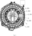
- outer barrel 101, outer barrel bottom; 2, locking structure; 201, locking motor; 202, bolt; 3, drum motor; 301, rotor; 302, locking groove; 4, position detection device; 401, permanent magnet; and 402, Hall sensor.
- orientation or position relation indicated by terms “upper”, “lower”, “inner”, “outer” and the like is based on the orientation or position relation shown in the accompanying drawings, and is only used for conveniently describing the present invention and simplifying the description, instead of indicating or implying that the indicated device or element has a specific orientation and is constructed and operated in the specific orientation, so that the terms cannot be understood as the limitation on the present invention.
- connection may be a fixed connection, a detachable connection, or an integrated connection; may be a mechanical connection or an electric connection; and may be a direct connection, and an indirect connection through an intermediate medium.
- connection may be a fixed connection, a detachable connection, or an integrated connection; may be a mechanical connection or an electric connection; and may be a direct connection, and an indirect connection through an intermediate medium.
- a determination method for locking a drum of washing appliance which is provided with a drum motor 3 for driving a drum to rotate, and a locking structure 2, comprises driving the drum to rotate at a set power output of the drum motor 3, the locking structure 2 generating a locking action for locking the drum, and being determined that the drum is locked by the locking structure 2 when a output current of the drum motor 3 is larger than a rated current.
- the locking structure 2 on the washing appliance is used for locking the drum at a locking position
- the drum motor 3 drives the drum to rotate at the set power output
- the locking structure 2 takes the locking action for locking the drum
- the drum continues to rotate, and it is determined that the drum is locked by the locking structure 2 when the output current of the drum motor 3 is larger than the rated current. It is can be accurately judged whether the drum is locked by the locking structure 2through the determination method, and therefore the drum locking accuracy can be improved.
- the locking structure 2 locks the drum at the locking position of the drum.
- the locking position of the drum refers to a position when the drum door is in a normal opening position.
- the drum is locked at the locking position by the locking structure 2, namely the drum door is locked at the normal opening position of the drum door by the locking structure 2.
- the locking structure 2 takes a locking action for locking the drum
- the drum motor 3 drives the drum to continuously rotate at a set power output
- an output current of the drum motor is detected to obtain the output current I 1 of the drum motor after the drum rotates for a certain time t.
- the drum motor 3 drives the drum to continuously rotate at the set power output.
- the output current of the drum motor 3 is detected after the drum rotates for a certain time t. If the output current of the drum motor is larger than the rated current, it is indicated that the locking structure 2 locks the drum. If the output current of the drum motor 3 is smaller than the rated current of the drum motor, it is indicated that the locking structure 2 fails to lock the drum. Through the comparison, it can be accurately determined that the drum is locked, and the drum locking accuracy is improved.
- the locking structure 2 includes a bolt 202 and a locking motor 201 for driving the bolt 202 to stretch out and draw back in a radial direction, and a rotor 301 of the drum motor 3 is provided with a locking groove 302.
- the locking motor 201 drives the bolt 202 to be inserted into the locking groove 302, and the drum is locked by the locking structure 2.
- the drum motor 3 is powered off to stop working.
- the drum motor 3 is powered off to stop working, and thus, locking of the drum in a position is completed;
- the locking motor 201 can drive the bolt 202 to abut against the locking motor 201, and is slightly positioned.
- the locking motor 201 can drive the bolt 202 to be accurately inserted into the locking groove 302.
- the locking motor 201 drives the bolt 202 to be detached from the drum motor 3, and the bolt 202 is reset.
- the drum motor 3 drives the drum to continuously rotate at a set power output, and whether the drum is locked by the locking structure 2 is determined again.
- the locking motor 201 drives the bolt 202 to be detached from the drum and the bolt 202 is restored to the original position, and the drum motor 3 drives the drum to continuously rotate at a set power output. The output current of the drum motor 3 is detected again, and the probability that the locking structure 2 locks the drum successfully is increased.
- the drum motor 3 drives the drum to rotate at a set power output
- the locking structure 2 takes a locking action for locking the drum
- the drum motor 3 drives the drum to continuously rotate at the set power output
- an output current of the drum motor 3 is detected to obtain an output current value I 1 of the drum motor 3 after the drum rotates for a certain time t;
- the washing appliance further includes a position detection device 4, and the position detection device 4 includes a Hall sensor 402 arranged on the outer barrel 1 and a permanent magnet arranged on a rotor 301 of the drum motor 3.
- the drum motor 3 drives the drum to rotate at the set power output.
- the permanent magnet 401 on the rotor 301 of the drum motor 3 is detected through the Hall sensor 402 so as to detect whether the locking groove of the rotor is reached on a position. If the groove of the rotor is reached on a position, the locking structure 2 is prompted to take a locking action for locking the drum.
- the permanent magnet is arranged on the rotor 301 of the drum motor 3.
- the locking structure 2 starts to take a locking action for locking the drum, so that the bolt 202 of the locking motor 201 can be accurately inserted into the locking groove 302, and the accuracy of locking the drum is improved.
- a power of the drum motor is reduced to a set power, and the drum motor 3 drives the drum to rotate at the set power output.
- the drum motor 3 if the drum motor 3 is suddenly braked when the power of the drum motor and the rotating speed of the drum are relatively high, the impact force on the bolt 202 of the locking structure 2 is large, so the bolt can be cut off by the instant impact force, and the washing appliance is broken down. Thereby the power of the drum motor 3 needs to be reduced to the set power in order to avoid the above situation to be happened.
- drum motor 3 and the locking motor 201 are both controlled by a controller.
- the controller controls the drum motor 3 to start rotating, reduce a rotating speed, stop rotating and the like, and the controller controls the locking motor 201 to run and controls the locking motor 201 to drive the bolt 202 to draw back.
- the locking structure 2 after the locking structure 2 fails to lock the drum and if it is detected that the number of times that the locking structure 2 fails to lock the drum exceeds the set number of times, the locking structure 2 stops locking, and the washing appliance sends out an alarm signal.
- the locking structure 2 after it is detected that the locking structure 2 fails to lock the drum for multiple times and the number of times of failure exceeds the number of times set by a system, the locking structure 2 is controlled to stop locking.
- the washing appliance gives an alarm to warn that the washing appliance is broken down, and the error rate of locking the drum is reduced.
- the washing appliance includes a drum for containing washing water and a drum motor for driving the drum to rotate.
- the washing appliance is applied to the determination method for locking of the drum of the washing appliance in the above technical solution, and the washing appliance is provided with a locking structure 2 for locking the drum at a locking position.
- the locking structure 2 arranged on the washing appliance can lock the drum for containing the washing water at the locking position, so that the drum door is locked at the normal opening position.
- the accuracy of locking the drum by the locking structure 2 is improved by determining whether the locking structure 2 successfully locks the drum at the locking position.
- the drum is a closed container for containing washing water when the washing appliance executes a washing program.
- the washing appliance includes an inner drum and an outer barrel 1, wherein the drum is used for containing washing water.
- a lifting rib is arranged on the side wall of the inner drum, and a containing cavity is formed in the lifting rib.
- a first through hole communicating with the inner space of the inner drum and a second through hole communicating with a gap between the inner drum and the outer barrel are formed in the wall of the containing cavity, and a control structure for controlling the first through hole and/or the second through hole to be opened and closed is arranged in the containing cavity.
- the inner drum is rotatably mounted in the outer barrel 1 of the washing appliance, and the locking structure 2 is mounted on an outer barrel bottom 101.
- the drum is rotatably mounted in the outer barrel 1 of the washing appliance as an inner drum.
- a locking structure 2 mounted on the outer barrel 1 locks the inner drum at the locking position, and the inner drum is locked to stop rotating, and a drum door of the inner drum is locked at a normal opening position.
- the locking structure 2 includes a bolt 202 and a locking motor 201 for driving the bolt 202 to stretch out and draw back in a radial direction.
- a rotor of the drum motor 3 is provided with a locking groove 302 matched with the bolt 202, and the bolt 202 is driven to be inserted into or detached from the locking groove 302 by the locking motor 201.
- the drum motor 3 is powered off to stop working.
- the bolt of the locking structure can be a motor shaft of the locking motor 201.
- the washing appliance includes a drum for containing washing water and the locking structure 2 being configured to be mounted on a shell of the washing appliance.
- the locking structure 2 includes a bolt 202 and a locking motor 201 for driving the bolt 202 to stretch out and draw back in a radial direction.
- a rotor of the drum motor 3 is provided with a locking groove 302 matched with the bolt, and the bolt is driven to be inserted into or detached from the locking groove 302 by the locking motor 201.
- the washing appliance includes a drum and an outer barrel, and the outer barrel is used for containing washing water.
- the locking structure 2 can be mounted on the outer barrel of the washing appliance.
- a rotor of the drum motor 3 is provided with a locking groove matched with the bolt 202, and the bolt 202 is driven to be inserted into or detached from the locking groove by the locking motor 201.
- a position detection device 4 used for detecting the position of the rotor 301 of the drum motor 3 is further included.
- a first part of the position detection device 4 is arranged on the rotor 301 of the drum motor 3
- a second part of the position detection device 4 is arranged on the outer barrel, and the first part of the position detection device 4 interacts with the second part of the position detection device 4 to generate corresponding position information during working.
- the position of the other part of the position detection device 4 is arranged corresponding to the locking position of the drum.
- the position detection device 4 can be composed of a mechanical element, an electronic element, an electromagnetic element or other element or a complex thereof.
- the first part of the position detection device 4 rotates along with the rotor 301 of the drum motor 3. Along with continuous rotation of the first part of the position detection device 4, the first part of the position detection device 4 rotates to the position where the second part of the position detection device 4 is located and interacts with the second part of the position detection device 4 to generate corresponding position information, so that whether the locking groove in the rotor is reached a position is detected. If yes, the locking structure 2 generates a locking action for locking the drum.
- the position detection device 4 includes a permanent magnet 401 and a Hall sensor 402.
- the permanent magnet 401 is arranged on the rotor 301 of the drum motor 3, and the Hall sensor 402 is arranged on the outer barrel 1.
- the Hall sensor 402 and the permanent magnet 401 interact with each other to generate corresponding position information when working.
- the Hall sensor 402 is arranged at the position, corresponding to the bolt, of the outer barrel 1, and the permanent magnet is arranged at the position, corresponding to the locking groove 302, of the drum motor 3.
- the locking structure takes a locking action for locking the drum, and the drum motor 3 drives the drum to continuously rotate at the set power output.
- the drum rotates for a certain time t
- the drum rotates to the position where a groove opening of the locking groove 302 is aligned with the bolt of the locking structure
- the drum rotates to the locking position
- the drum door reaches the normal opening position
- the locking motor 201 drives the bolt to be inserted into the locking groove 302, and the drum is locked at the locking position.
- the permanent magnet is arranged on the outer barrel 1
- the Hall sensor is arranged on the rotor 301 of the drum motor 3
- the Hall sensor rotates along with the rotor 301 of the drum motor 3.
- the position detection device 4 includes a photoelectric sensor and a luminous body.
- the photoelectric sensor is arranged on the rotor 301 of the drum motor 3, and the luminous body is arranged on the outer barrel 1; and the photoelectric sensor and the luminous body interact with each other to generate corresponding position information during working.
- the luminous body is arranged at the position, corresponding to the bolt 202, of the outer barrel 1
- the photoelectric sensor is arranged at the position, corresponding to the locking groove 302, of the drum.
- the locking structure takes a locking action for locking the drum, and the drum motor drives the drum to continuously rotate at the set power output.
- the drum rotates for a certain time t
- the drum rotates to the position where the locking groove 302 is aligned with the bolt 202 of the locking structure 2
- the drum door reaches the normal opening position
- the locking motor 201 releases the bolt 202 to stretch out and be inserted into the locking groove 302, and the drum is locked at the locking position.
- the photoelectric sensor is arranged on the outer barrel 1
- the luminous body is arranged on the rotor 301 of the drum motor 3, and the photoelectric sensor rotates along with the luminous body.
Landscapes
- Engineering & Computer Science (AREA)
- Textile Engineering (AREA)
- Control Of Washing Machine And Dryer (AREA)
- Main Body Construction Of Washing Machines And Laundry Dryers (AREA)
Claims (10)
- Verfahren zum Bestimmen einer Verriegelung einer Trommel eines Waschgeräts, wobei das Waschgerät einen Trommelmotor (3) zum Antreiben einer Trommel dazu, sich zu drehen, und eine Verriegelungsstruktur (2) aufweist, umfassend:Antrieben der Trommel dazu, sich bei einer festgelegten Leistungsausgabe durch den Trommelmotor (3) zu drehen,Durchführen einer Verriegelungsaktion zum Verriegeln der Trommel durch die Verriegelungsstruktur (2) undBestimmen, dass die Trommel durch die Verriegelungsstruktur (2) verriegelt ist, wenn ein Ausgangsstrom des Trommelmotors (3) größer als ein Nennstrom ist, dadurch gekennzeichnet, dass die Verriegelungsstruktur (2) die Verriegelungsaktion zum Verriegeln der Trommel durchführt, der Trommelmotor (3) die Trommel dazu antreibt, sich bei der festgelegten Leistungsausgabe kontinuierlich zu drehen, und der Ausgangsstrom des Trommelmotors (3) erfasst wird, um den Ausgangsstrom I1 des Trommelmotors (3) zu erhalten, nachdem die Trommel sich für eine gewisse Zeit t gedreht hat; wobei,wenn I1 > I0 ist, die Trommel durch die Verriegelungsstruktur (2) verriegelt ist; und, wenn I1 < I0 ist, das Verriegeln der Trommel durch die Verriegelungsstruktur (2) fehlgeschlagen ist, wobei I0 ein Nennstromwert ist.
- Verfahren zum Bestimmen der Verriegelung der Trommel des Waschgeräts nach Anspruch 1, wobei die Verriegelungsstruktur (2) einen Bolzen (202) aufweist sowie einen Verriegelungsmotor (201) zum Antreiben des Bolzens (202) dazu, in radialer Richtung auszufahren und einzufahren, und ein Rotor (301) des Trommelmotors (3) mit einer Verriegelungsnut (302) versehen ist;
wobei, nachdem sich die Trommel für eine gewisse Zeit t gedreht hat, der Bolzen (202) der Verriegelungsstruktur (2) mit der Verriegelungsnut (302) ausgerichtet ist, der Verriegelungsmotor (201) den Bolzen (202) dazu antreibt, in die Verriegelungsnut (302) eingeführt zu werden, und die Trommel durch die Verriegelungsstruktur (2) verriegelt wird. - Verfahren zum Bestimmen der Verriegelung der Trommel des Waschgeräts nach Anspruch 2, wobei, nachdem das Verriegeln der Trommel durch die Verriegelungsstruktur (2) fehlgeschlagen ist, der Verriegelungsmotor (201) den Bolzen (202) dazu antreibt, sich vom Trommelmotor (3) zu lösen, der Bolzen (202) zurückgesetzt wird, der Trommelmotor (3) die Trommel dazu antreibt, sich bei der festgelegten Leistungsausgabe kontinuierlich zu drehen, und erneut bestimmt wird, ob die Trommel durch die Verriegelungsstruktur (2) verriegelt ist.
- Verfahren zum Bestimmen der Verriegelung der Trommel des Waschgeräts nach Anspruch 3, umfassend:S1, Antreiben der Trommel dazu, sich zu drehen, durch den Trommelmotor (3) bei der festgelegten Leistungsausgabe, Durchführen der Verriegelungsaktion zum Verriegeln der Trommel durch die Verriegelungsstruktur (2), Antreiben der Trommel dazu, sich kontinuierlich zu drehen, durch den Trommelmotor (3) bei der festgelegten Leistungsausgabe und Erfassen des Ausgangsstroms des Trommelmotors, um den Ausgangsstromwert I1 des Trommelmotors (3) zu erhalten, nachdem sich die Trommel für eine gewisse Zeit t gedreht hat;S2, Vergleichen des Ausgangsstromwerts I1 des Trommelmotors (3) mit einem Nennstromwert und, wenn I1 > I0 ist, Ausführen von Schritt S3; und, wenn I1 < I0 ist, Ausführen von Schritt S5;S3, wenn bestimmt wird, dass der Verriegelungsmotor (201) den Bolzen (202) dazu antreibt, in die Verriegelungsnut (302) eingeführt zu werden, und die Trommel durch die Verriegelungsstruktur (2) verriegelt ist, Ausführen von Schritt S4;S4, Ausschalten des Trommelmotors (3), sodass er den Betrieb einstellt; undS5, Antreiben des Bolzens (202) dazu, sich von dem Trommelmotor (3) zu lösen, durch den Verriegelungsmotor (201), Zurücksetzen des Bolzens (202) und Antreiben der Trommel dazu, sich bei der festgelegten Leistungsausgabe kontinuierlich zu drehen, durch den Trommelmotor (3) und erneutes Ausführen von Schritt S1.
- Verfahren zum Bestimmen der Verriegelung der Trommel des Waschgeräts nach einem der Ansprüche 1-4, wobei der Trommelmotor (3) einen Stoppbefehl erhält, die Leistung des Trommelmotors (3) auf eine festgelegte Leistung reduziert wird und der Trommelmotor (3) die Trommel bei der festgelegten Leistungsausgabe dazu antreibt, sich zu drehen.
- Verfahren zum Bestimmen der Verriegelung der Trommel des Waschgeräts nach einem der Ansprüche 1-4, wobei, nachdem das Verriegeln der Trommel durch die Verriegelungsstruktur (2) fehlgeschlagen ist und wenn erkannt wird, dass die Anzahl der fehlgeschlagenen Versuche der Verriegelungsstruktur (2), die Trommel zu verriegeln, eine festgelegte Anzahl übersteigt, die Verriegelungsstruktur (2) das Verriegeln beendet und das Waschgerät ein Alarmsignal aussendet.
- Verfahren zum Bestimmen der Verriegelung der Trommel des Waschgeräts nach Anspruch 2, wobei, nachdem der Bolzen (202) in die Verriegelungsnut (302) eingeführt worden ist, um die Trommel zu verriegeln, der Trommelmotor (3) ausgeschaltet wird, sodass er den Betrieb einstellt.
- Waschgerät mit einer Trommel zur Aufnahme von Waschwasser, einem Trommelmotor (3) zum Antreiben der Trommel dazu, sich zu drehen, und einer Verriegelungsstruktur (2) zur Verriegelung der Trommel,
wobei das Waschgerät dazu eingerichtet ist, ein Verfahren zum Bestimmen der Verriegelung der Trommel des Waschgeräts nach einem der Ansprüche 1-7 durchzuführen. - Waschgerät nach Anspruch 8, wobei die Trommel ein geschlossener Behälter zur Aufnahme von Waschwasser ist, wenn das Waschgerät ein Waschprogramm ausführt.
- Waschgerät nach Anspruch 8 oder 9, wobei die Trommel drehbar in einer äußeren Tonne (1) des Waschgeräts montiert ist und die Verriegelungsstruktur (2) an einem äußeren Tonnenboden (101) montiert ist;die Verriegelungsstruktur (2) einen Bolzen (202) aufweist sowie einen Verriegelungsmotor (201) zum Antreiben des Bolzens (202) dazu, in radialer Richtung auszufahren und einzufahren,ein Rotor (301) des Trommelmotors (3) mit einer Verriegelungsnut (302) versehen ist, die mit dem Bolzen (202) übereinstimmt, und der Bolzen (202) unter Antrieb durch den Verriegelungsmotor (201) dazu angetrieben wird, in die Verriegelungsnut (302) eingeführt zu werden, oder dazu angetrieben wird, von der Verriegelungsnut (302) gelöst zu werden.
Applications Claiming Priority (2)
| Application Number | Priority Date | Filing Date | Title |
|---|---|---|---|
| CN201910769300.9A CN112411115B (zh) | 2019-08-20 | 2019-08-20 | 一种洗涤设备及洗涤设备滚筒锁定的判定方法 |
| PCT/CN2020/109903 WO2021032101A1 (zh) | 2019-08-20 | 2020-08-19 | 一种洗涤设备及洗涤设备滚筒锁定的判定方法 |
Publications (4)
| Publication Number | Publication Date |
|---|---|
| EP4019687A1 EP4019687A1 (de) | 2022-06-29 |
| EP4019687A4 EP4019687A4 (de) | 2022-10-19 |
| EP4019687C0 EP4019687C0 (de) | 2024-08-14 |
| EP4019687B1 true EP4019687B1 (de) | 2024-08-14 |
Family
ID=74659941
Family Applications (1)
| Application Number | Title | Priority Date | Filing Date |
|---|---|---|---|
| EP20853830.6A Active EP4019687B1 (de) | 2019-08-20 | 2020-08-19 | Waschvorrichtung und verfahren zur bestimmung der trommelverriegelung |
Country Status (5)
| Country | Link |
|---|---|
| US (1) | US11891745B2 (de) |
| EP (1) | EP4019687B1 (de) |
| JP (1) | JP2022553604A (de) |
| CN (1) | CN112411115B (de) |
| WO (1) | WO2021032101A1 (de) |
Families Citing this family (1)
| Publication number | Priority date | Publication date | Assignee | Title |
|---|---|---|---|---|
| US11611704B2 (en) * | 2020-03-17 | 2023-03-21 | Global Mixed-Mode Technology Inc. | Motor controller |
Citations (1)
| Publication number | Priority date | Publication date | Assignee | Title |
|---|---|---|---|---|
| JP2004344463A (ja) * | 2003-05-23 | 2004-12-09 | Sanyo Electric Co Ltd | ドラム式洗濯機 |
Family Cites Families (15)
| Publication number | Priority date | Publication date | Assignee | Title |
|---|---|---|---|---|
| JP2834855B2 (ja) * | 1990-06-26 | 1998-12-14 | 三洋電機株式会社 | ドラム式洗濯機 |
| FR2699563B1 (fr) | 1992-12-22 | 1995-01-20 | App Menagers Ind | Dispositif d'arrêt en position du tambour et de déverrouillage rapide de la porte d'accès d'une machine à tambour horizontal. |
| JP3609789B2 (ja) * | 2002-03-06 | 2005-01-12 | 三洋電機株式会社 | ドラム式洗濯機 |
| JP4179970B2 (ja) | 2003-11-14 | 2008-11-12 | 株式会社東芝 | ドラム式洗濯機 |
| KR100564442B1 (ko) | 2003-12-10 | 2006-03-29 | 엘지전자 주식회사 | 탑로딩방식 드럼 세탁기 |
| ITTO20040691A1 (it) * | 2004-10-08 | 2005-01-08 | Elbi Int Spa | Dispositivo di bloccaggio per un elemento mobile, in particolare per un cestello portabiancheria di una macchina lavatrice a carica dall'alto |
| CN101729012A (zh) | 2009-12-18 | 2010-06-09 | 合肥荣事达三洋电器股份有限公司 | 顶开式滚筒洗衣机的准确停机定位的电机装置 |
| JP5573596B2 (ja) * | 2010-10-28 | 2014-08-20 | パナソニック株式会社 | ドラム式洗濯機 |
| CN106480647B (zh) * | 2015-08-31 | 2019-11-12 | 青岛海尔洗衣机有限公司 | 一种内桶的锁止机构及洗衣机 |
| JP2017055579A (ja) | 2015-09-10 | 2017-03-16 | 京セラドキュメントソリューションズ株式会社 | モーターロック検出装置 |
| CN107022882B (zh) * | 2016-02-02 | 2020-03-17 | 青岛海尔洗衣机有限公司 | 一种洗衣机上盖自动开关控制装置及方法 |
| JP6779482B2 (ja) * | 2016-08-29 | 2020-11-04 | 青島海爾洗衣机有限公司QingDao Haier Washing Machine Co.,Ltd. | ドラム式洗濯機 |
| KR102412036B1 (ko) * | 2017-07-14 | 2022-06-22 | 삼성전자주식회사 | 세탁기 및 그 제어 방법 |
| CN109402940B (zh) * | 2017-08-16 | 2021-05-25 | 青岛胶南海尔洗衣机有限公司 | 用于衣物处理设备的内筒定位方法和衣物处理设备 |
| CN109518418B (zh) * | 2017-09-18 | 2021-07-23 | 青岛胶南海尔洗衣机有限公司 | 用于顶开式衣物处理设备的内筒位置的微调方法 |
-
2019
- 2019-08-20 CN CN201910769300.9A patent/CN112411115B/zh active Active
-
2020
- 2020-08-19 WO PCT/CN2020/109903 patent/WO2021032101A1/zh not_active Ceased
- 2020-08-19 US US17/636,058 patent/US11891745B2/en active Active
- 2020-08-19 JP JP2022510144A patent/JP2022553604A/ja active Pending
- 2020-08-19 EP EP20853830.6A patent/EP4019687B1/de active Active
Patent Citations (1)
| Publication number | Priority date | Publication date | Assignee | Title |
|---|---|---|---|---|
| JP2004344463A (ja) * | 2003-05-23 | 2004-12-09 | Sanyo Electric Co Ltd | ドラム式洗濯機 |
Also Published As
| Publication number | Publication date |
|---|---|
| EP4019687A4 (de) | 2022-10-19 |
| EP4019687A1 (de) | 2022-06-29 |
| EP4019687C0 (de) | 2024-08-14 |
| CN112411115B (zh) | 2022-06-10 |
| CN112411115A (zh) | 2021-02-26 |
| JP2022553604A (ja) | 2022-12-26 |
| US20220282419A1 (en) | 2022-09-08 |
| WO2021032101A1 (zh) | 2021-02-25 |
| US11891745B2 (en) | 2024-02-06 |
Similar Documents
| Publication | Publication Date | Title |
|---|---|---|
| JP5573596B2 (ja) | ドラム式洗濯機 | |
| WO2018033025A1 (zh) | 电子膨胀阀、控制系统以及控制方法 | |
| KR20100118169A (ko) | 세탁기 및 그 제어 방법 | |
| JP2004344463A (ja) | ドラム式洗濯機 | |
| EP4019687B1 (de) | Waschvorrichtung und verfahren zur bestimmung der trommelverriegelung | |
| JP4822974B2 (ja) | 洗濯機 | |
| CN102899849B (zh) | 双桶式洗衣机 | |
| JP7442048B2 (ja) | 洗濯機 | |
| JP4500368B1 (ja) | 蓋ロック装置および蓋ロック装置を備えた電気洗濯機 | |
| EP4019689A1 (de) | Waschmaschine und verfahren zur bestimmung, ob die wäschetrommel der waschmaschine entriegelt ist | |
| CN108842371A (zh) | 一种洗衣机控制方法 | |
| CN106460281A (zh) | 滚筒式洗衣机 | |
| JP2008307414A (ja) | 洗濯機 | |
| JP6706738B2 (ja) | ドラム式洗濯機 | |
| JP4806436B2 (ja) | 洗濯機 | |
| KR100280606B1 (ko) | 세탁기의 물 넘침 방지 제어 방법 | |
| CN110535402A (zh) | 旋转电机的控制方法 | |
| JP2008307413A (ja) | 洗濯機 | |
| CN111020974A (zh) | 一种电机控制方法、洗衣机和电子设备可读存储介质 | |
| CN113802329A (zh) | 洗衣机 | |
| WO2025098235A1 (zh) | 一种滚筒洗衣机及控制方法 | |
| KR101053590B1 (ko) | 드럼 세탁기의 제어 방법 | |
| WO2021068734A1 (zh) | 一种衣物处理设备的控制方法 | |
| KR100688159B1 (ko) | 세탁기의 포량감지방법 | |
| JPH0788284A (ja) | 洗濯機 |
Legal Events
| Date | Code | Title | Description |
|---|---|---|---|
| STAA | Information on the status of an ep patent application or granted ep patent |
Free format text: STATUS: THE INTERNATIONAL PUBLICATION HAS BEEN MADE |
|
| PUAI | Public reference made under article 153(3) epc to a published international application that has entered the european phase |
Free format text: ORIGINAL CODE: 0009012 |
|
| STAA | Information on the status of an ep patent application or granted ep patent |
Free format text: STATUS: REQUEST FOR EXAMINATION WAS MADE |
|
| 17P | Request for examination filed |
Effective date: 20220309 |
|
| AK | Designated contracting states |
Kind code of ref document: A1 Designated state(s): AL AT BE BG CH CY CZ DE DK EE ES FI FR GB GR HR HU IE IS IT LI LT LU LV MC MK MT NL NO PL PT RO RS SE SI SK SM TR |
|
| A4 | Supplementary search report drawn up and despatched |
Effective date: 20220921 |
|
| RIC1 | Information provided on ipc code assigned before grant |
Ipc: D06F 105/00 20200101ALN20220915BHEP Ipc: D06F 103/46 20200101ALN20220915BHEP Ipc: D06F 103/38 20200101ALN20220915BHEP Ipc: D06F 23/02 20060101ALN20220915BHEP Ipc: D06F 33/47 20200101ALI20220915BHEP Ipc: D06F 37/30 20200101ALI20220915BHEP Ipc: D06F 37/26 20060101AFI20220915BHEP |
|
| DAV | Request for validation of the european patent (deleted) | ||
| DAX | Request for extension of the european patent (deleted) | ||
| REG | Reference to a national code |
Ref country code: DE Ref legal event code: R079 Free format text: PREVIOUS MAIN CLASS: D06F0033000000 Ipc: D06F0037260000 Ref document number: 602020035939 Country of ref document: DE |
|
| GRAP | Despatch of communication of intention to grant a patent |
Free format text: ORIGINAL CODE: EPIDOSNIGR1 |
|
| STAA | Information on the status of an ep patent application or granted ep patent |
Free format text: STATUS: GRANT OF PATENT IS INTENDED |
|
| RIC1 | Information provided on ipc code assigned before grant |
Ipc: D06F 105/00 20200101ALN20240228BHEP Ipc: D06F 103/46 20200101ALN20240228BHEP Ipc: D06F 103/38 20200101ALN20240228BHEP Ipc: D06F 23/02 20060101ALN20240228BHEP Ipc: D06F 33/47 20200101ALI20240228BHEP Ipc: D06F 37/30 20200101ALI20240228BHEP Ipc: D06F 37/26 20060101AFI20240228BHEP |
|
| INTG | Intention to grant announced |
Effective date: 20240325 |
|
| RAP1 | Party data changed (applicant data changed or rights of an application transferred) |
Owner name: HAIER SMART HOME CO., LTD. Owner name: QINGDAO HAIER LAUNDRY ELECTRIC APPLIANCES CO., LTD. |
|
| GRAS | Grant fee paid |
Free format text: ORIGINAL CODE: EPIDOSNIGR3 |
|
| GRAA | (expected) grant |
Free format text: ORIGINAL CODE: 0009210 |
|
| STAA | Information on the status of an ep patent application or granted ep patent |
Free format text: STATUS: THE PATENT HAS BEEN GRANTED |
|
| AK | Designated contracting states |
Kind code of ref document: B1 Designated state(s): AL AT BE BG CH CY CZ DE DK EE ES FI FR GB GR HR HU IE IS IT LI LT LU LV MC MK MT NL NO PL PT RO RS SE SI SK SM TR |
|
| REG | Reference to a national code |
Ref country code: GB Ref legal event code: FG4D |
|
| REG | Reference to a national code |
Ref country code: CH Ref legal event code: EP |
|
| REG | Reference to a national code |
Ref country code: DE Ref legal event code: R096 Ref document number: 602020035939 Country of ref document: DE |
|
| REG | Reference to a national code |
Ref country code: IE Ref legal event code: FG4D |
|
| U01 | Request for unitary effect filed |
Effective date: 20240904 |
|
| U07 | Unitary effect registered |
Designated state(s): AT BE BG DE DK EE FI FR IT LT LU LV MT NL PT RO SE SI Effective date: 20240923 |
|
| U20 | Renewal fee for the european patent with unitary effect paid |
Year of fee payment: 5 Effective date: 20241205 |
|
| PG25 | Lapsed in a contracting state [announced via postgrant information from national office to epo] |
Ref country code: NO Free format text: LAPSE BECAUSE OF FAILURE TO SUBMIT A TRANSLATION OF THE DESCRIPTION OR TO PAY THE FEE WITHIN THE PRESCRIBED TIME-LIMIT Effective date: 20241114 |
|
| PG25 | Lapsed in a contracting state [announced via postgrant information from national office to epo] |
Ref country code: PL Free format text: LAPSE BECAUSE OF FAILURE TO SUBMIT A TRANSLATION OF THE DESCRIPTION OR TO PAY THE FEE WITHIN THE PRESCRIBED TIME-LIMIT Effective date: 20240814 Ref country code: GR Free format text: LAPSE BECAUSE OF FAILURE TO SUBMIT A TRANSLATION OF THE DESCRIPTION OR TO PAY THE FEE WITHIN THE PRESCRIBED TIME-LIMIT Effective date: 20241115 |
|
| PG25 | Lapsed in a contracting state [announced via postgrant information from national office to epo] |
Ref country code: IS Free format text: LAPSE BECAUSE OF FAILURE TO SUBMIT A TRANSLATION OF THE DESCRIPTION OR TO PAY THE FEE WITHIN THE PRESCRIBED TIME-LIMIT Effective date: 20241214 |
|
| PG25 | Lapsed in a contracting state [announced via postgrant information from national office to epo] |
Ref country code: HR Free format text: LAPSE BECAUSE OF FAILURE TO SUBMIT A TRANSLATION OF THE DESCRIPTION OR TO PAY THE FEE WITHIN THE PRESCRIBED TIME-LIMIT Effective date: 20240814 |
|
| PG25 | Lapsed in a contracting state [announced via postgrant information from national office to epo] |
Ref country code: RS Free format text: LAPSE BECAUSE OF FAILURE TO SUBMIT A TRANSLATION OF THE DESCRIPTION OR TO PAY THE FEE WITHIN THE PRESCRIBED TIME-LIMIT Effective date: 20241114 Ref country code: ES Free format text: LAPSE BECAUSE OF FAILURE TO SUBMIT A TRANSLATION OF THE DESCRIPTION OR TO PAY THE FEE WITHIN THE PRESCRIBED TIME-LIMIT Effective date: 20240814 |
|
| PG25 | Lapsed in a contracting state [announced via postgrant information from national office to epo] |
Ref country code: RS Free format text: LAPSE BECAUSE OF FAILURE TO SUBMIT A TRANSLATION OF THE DESCRIPTION OR TO PAY THE FEE WITHIN THE PRESCRIBED TIME-LIMIT Effective date: 20241114 Ref country code: PL Free format text: LAPSE BECAUSE OF FAILURE TO SUBMIT A TRANSLATION OF THE DESCRIPTION OR TO PAY THE FEE WITHIN THE PRESCRIBED TIME-LIMIT Effective date: 20240814 Ref country code: NO Free format text: LAPSE BECAUSE OF FAILURE TO SUBMIT A TRANSLATION OF THE DESCRIPTION OR TO PAY THE FEE WITHIN THE PRESCRIBED TIME-LIMIT Effective date: 20241114 Ref country code: IS Free format text: LAPSE BECAUSE OF FAILURE TO SUBMIT A TRANSLATION OF THE DESCRIPTION OR TO PAY THE FEE WITHIN THE PRESCRIBED TIME-LIMIT Effective date: 20241214 Ref country code: HR Free format text: LAPSE BECAUSE OF FAILURE TO SUBMIT A TRANSLATION OF THE DESCRIPTION OR TO PAY THE FEE WITHIN THE PRESCRIBED TIME-LIMIT Effective date: 20240814 Ref country code: GR Free format text: LAPSE BECAUSE OF FAILURE TO SUBMIT A TRANSLATION OF THE DESCRIPTION OR TO PAY THE FEE WITHIN THE PRESCRIBED TIME-LIMIT Effective date: 20241115 Ref country code: ES Free format text: LAPSE BECAUSE OF FAILURE TO SUBMIT A TRANSLATION OF THE DESCRIPTION OR TO PAY THE FEE WITHIN THE PRESCRIBED TIME-LIMIT Effective date: 20240814 |
|
| REG | Reference to a national code |
Ref country code: CH Ref legal event code: PL |
|
| PG25 | Lapsed in a contracting state [announced via postgrant information from national office to epo] |
Ref country code: SM Free format text: LAPSE BECAUSE OF FAILURE TO SUBMIT A TRANSLATION OF THE DESCRIPTION OR TO PAY THE FEE WITHIN THE PRESCRIBED TIME-LIMIT Effective date: 20240814 |
|
| PG25 | Lapsed in a contracting state [announced via postgrant information from national office to epo] |
Ref country code: CH Free format text: LAPSE BECAUSE OF NON-PAYMENT OF DUE FEES Effective date: 20240831 |
|
| PG25 | Lapsed in a contracting state [announced via postgrant information from national office to epo] |
Ref country code: CZ Free format text: LAPSE BECAUSE OF FAILURE TO SUBMIT A TRANSLATION OF THE DESCRIPTION OR TO PAY THE FEE WITHIN THE PRESCRIBED TIME-LIMIT Effective date: 20240814 |
|
| PG25 | Lapsed in a contracting state [announced via postgrant information from national office to epo] |
Ref country code: SK Free format text: LAPSE BECAUSE OF FAILURE TO SUBMIT A TRANSLATION OF THE DESCRIPTION OR TO PAY THE FEE WITHIN THE PRESCRIBED TIME-LIMIT Effective date: 20240814 |
|
| PLBE | No opposition filed within time limit |
Free format text: ORIGINAL CODE: 0009261 |
|
| STAA | Information on the status of an ep patent application or granted ep patent |
Free format text: STATUS: NO OPPOSITION FILED WITHIN TIME LIMIT |
|
| PG25 | Lapsed in a contracting state [announced via postgrant information from national office to epo] |
Ref country code: MC Free format text: LAPSE BECAUSE OF FAILURE TO SUBMIT A TRANSLATION OF THE DESCRIPTION OR TO PAY THE FEE WITHIN THE PRESCRIBED TIME-LIMIT Effective date: 20240814 |
|
| 26N | No opposition filed |
Effective date: 20250515 |
|
| GBPC | Gb: european patent ceased through non-payment of renewal fee |
Effective date: 20241114 |
|
| PG25 | Lapsed in a contracting state [announced via postgrant information from national office to epo] |
Ref country code: IE Free format text: LAPSE BECAUSE OF NON-PAYMENT OF DUE FEES Effective date: 20240819 |
|
| U20 | Renewal fee for the european patent with unitary effect paid |
Year of fee payment: 6 Effective date: 20250826 |
|
| PG25 | Lapsed in a contracting state [announced via postgrant information from national office to epo] |
Ref country code: GB Free format text: LAPSE BECAUSE OF NON-PAYMENT OF DUE FEES Effective date: 20241114 |
|
| PG25 | Lapsed in a contracting state [announced via postgrant information from national office to epo] |
Ref country code: CY Free format text: LAPSE BECAUSE OF FAILURE TO SUBMIT A TRANSLATION OF THE DESCRIPTION OR TO PAY THE FEE WITHIN THE PRESCRIBED TIME-LIMIT; INVALID AB INITIO Effective date: 20200819 |
|
| PG25 | Lapsed in a contracting state [announced via postgrant information from national office to epo] |
Ref country code: HU Free format text: LAPSE BECAUSE OF FAILURE TO SUBMIT A TRANSLATION OF THE DESCRIPTION OR TO PAY THE FEE WITHIN THE PRESCRIBED TIME-LIMIT; INVALID AB INITIO Effective date: 20200819 |