EP4011806B1 - Containerhandhabungsfahrzeug mit einem ersten und einem zweiten abschnitt und einer anordnung von motoren in einem zweiten abschnitt zum antreiben mindestens eines rades eines jeden radsatzes - Google Patents
Containerhandhabungsfahrzeug mit einem ersten und einem zweiten abschnitt und einer anordnung von motoren in einem zweiten abschnitt zum antreiben mindestens eines rades eines jeden radsatzes Download PDFInfo
- Publication number
- EP4011806B1 EP4011806B1 EP22154825.8A EP22154825A EP4011806B1 EP 4011806 B1 EP4011806 B1 EP 4011806B1 EP 22154825 A EP22154825 A EP 22154825A EP 4011806 B1 EP4011806 B1 EP 4011806B1
- Authority
- EP
- European Patent Office
- Prior art keywords
- wheels
- section
- container handling
- grid
- vehicle
- Prior art date
- Legal status (The legal status is an assumption and is not a legal conclusion. Google has not performed a legal analysis and makes no representation as to the accuracy of the status listed.)
- Active
Links
Images


Classifications
-
- B—PERFORMING OPERATIONS; TRANSPORTING
- B65—CONVEYING; PACKING; STORING; HANDLING THIN OR FILAMENTARY MATERIAL
- B65G—TRANSPORT OR STORAGE DEVICES, e.g. CONVEYORS FOR LOADING OR TIPPING, SHOP CONVEYOR SYSTEMS OR PNEUMATIC TUBE CONVEYORS
- B65G1/00—Storing articles, individually or in orderly arrangement, in warehouses or magazines
- B65G1/02—Storage devices
- B65G1/04—Storage devices mechanical
- B65G1/0464—Storage devices mechanical with access from above
-
- B—PERFORMING OPERATIONS; TRANSPORTING
- B65—CONVEYING; PACKING; STORING; HANDLING THIN OR FILAMENTARY MATERIAL
- B65G—TRANSPORT OR STORAGE DEVICES, e.g. CONVEYORS FOR LOADING OR TIPPING, SHOP CONVEYOR SYSTEMS OR PNEUMATIC TUBE CONVEYORS
- B65G1/00—Storing articles, individually or in orderly arrangement, in warehouses or magazines
- B65G1/02—Storage devices
- B65G1/04—Storage devices mechanical
- B65G1/0478—Storage devices mechanical for matrix-arrangements
-
- B—PERFORMING OPERATIONS; TRANSPORTING
- B65—CONVEYING; PACKING; STORING; HANDLING THIN OR FILAMENTARY MATERIAL
- B65G—TRANSPORT OR STORAGE DEVICES, e.g. CONVEYORS FOR LOADING OR TIPPING, SHOP CONVEYOR SYSTEMS OR PNEUMATIC TUBE CONVEYORS
- B65G1/00—Storing articles, individually or in orderly arrangement, in warehouses or magazines
- B65G1/02—Storage devices
- B65G1/04—Storage devices mechanical
- B65G1/06—Storage devices mechanical with means for presenting articles for removal at predetermined position or level
- B65G1/065—Storage devices mechanical with means for presenting articles for removal at predetermined position or level with self propelled cars
-
- B—PERFORMING OPERATIONS; TRANSPORTING
- B65—CONVEYING; PACKING; STORING; HANDLING THIN OR FILAMENTARY MATERIAL
- B65G—TRANSPORT OR STORAGE DEVICES, e.g. CONVEYORS FOR LOADING OR TIPPING, SHOP CONVEYOR SYSTEMS OR PNEUMATIC TUBE CONVEYORS
- B65G1/00—Storing articles, individually or in orderly arrangement, in warehouses or magazines
- B65G1/02—Storage devices
- B65G1/04—Storage devices mechanical
- B65G1/137—Storage devices mechanical with arrangements or automatic control means for selecting which articles are to be removed
-
- B—PERFORMING OPERATIONS; TRANSPORTING
- B65—CONVEYING; PACKING; STORING; HANDLING THIN OR FILAMENTARY MATERIAL
- B65G—TRANSPORT OR STORAGE DEVICES, e.g. CONVEYORS FOR LOADING OR TIPPING, SHOP CONVEYOR SYSTEMS OR PNEUMATIC TUBE CONVEYORS
- B65G2201/00—Indexing codes relating to handling devices, e.g. conveyors, characterised by the type of product or load being conveyed or handled
- B65G2201/02—Articles
- B65G2201/0235—Containers
- B65G2201/0258—Trays, totes or bins
Definitions
- the present invention relates to the field container handling vehicles for automated storage and retrieval systems and to automated storage and retrieval systems comprising such container handling vehicles.
- the Applicant's already known AutoStore system is a storage system comprising a three-dimensional storage grid structure wherein storage containers/containers are stacked on top of each other to a certain height.
- Such a prior art system is shown in fig. 1 .
- the storage system is disclosed in detail in for instance NO317366 and WO 2014/090684 A1 .
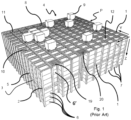
- Fig. 1 discloses a framework structure of a typical prior art automated storage and retrieval system 1 and figures 2a and 2b disclose known container handling vehicles of such a system.
- the framework structure comprises a plurality of upright members/profiles 2 and a plurality of horizontal members 3, which are supported by the upright members 2.
- the members 2, 3 may typically be made of metal, e.g. extruded aluminium profiles.
- the framework structure defines a storage grid 4 comprising multiple grid opening/ columns 12 arranged in rows.
- a majority of the grid columns 12 are storage columns 5 in which storage containers 6, also known as containers or bins, are stacked one on top of another to form stacks 7.
- Each storage container 6 (or container for short) may typically hold a plurality of product items (not shown), and the product items within a storage container 6 may be identical, or may be of different product types depending on the application.
- the framework structure guards against horizontal movement of the stacks 7 of storage containers 6, and guides vertical movement of the containers 6, but does normally not otherwise support the storage containers 6 when stacked.
- the upper horizontal members 3 comprise a rail system 8 arranged in a grid pattern across the top of the grid columns 12, on which rail system 8 a plurality of container handling vehicles 9 are operated to raise storage containers 6 from and lower storage containers 6 into the storage columns 5, and also to transport the storage containers 6 above the storage columns 5.
- the rail system 8 comprises a first set of parallel rails 10 arranged to guide movement of the container handling vehicles 9 in a first direction X across the top of the frame structure, and a second set of parallel rails 11 arranged perpendicular to the first set of rails 10 to guide movement of the container handling vehicles 9 in a second direction Y, which is perpendicular to the first direction X, see fig. 3 .
- the rail system 8 defines an upper end of the storage columns 5, above which the container handling vehicles 9 can move laterally above the storage columns 5, i.e. in a plane, which is parallel to the horizontal X-Y plane.
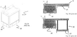
- Each container handling vehicle 9 comprises a vehicle body 13 and first and second sets of wheels 22, 23 which enable the lateral movement of the container handling vehicle 9, i.e. the movement in the X and Y directions.
- the first set of wheels 22 is arranged to engage with two adjacent rails of the first set 10 of rails
- the second set of wheels 23 arranged to engage with two adjacent rails of the second set 11 of rails.
- One of the set of wheels 22, 23 can be lifted and lowered, so that the first set of wheels 22 and/or the second set of wheels 23 can be engaged with their respective set of rails 10, 11 at any one time.
- Each container handling vehicle 9 also comprises a lifting device 18 (not shown in fig. 1 and 2a , but visible in fig. 2b ) for vertical transportation of storage containers 6, e.g. raising a storage container 6 from and lowering a storage container 6 into a storage column 5.
- the lifting device 18 comprises a lifting frame (not shown in fig. 2a , but similar to the one shown in fig. 2b labelled 17) which is adapted to engage a storage container 6, which lifting frame can be lowered from the vehicle body 13 so that the position of the lifting frame with respect to the vehicle body 13 can be adjusted in a third direction Z, which is orthogonal the first direction X and the second direction Y.
- Each container handling vehicle 9 comprises a storage compartment or space for receiving and stowing a storage container 6 when transporting the storage container 6 across the grid 4.
- the storage space may comprise a cavity 21 arranged centrally within the vehicle body 13, e.g. as is described in WO2014/090684A1 .
- the container handling vehicles may have a cantilever construction, as is described in NO317366.
- the single cell container handling vehicles 9 may have a footprint F, i.e. a horizontal periphery in the X and Y directions (see fig. 4 ), which is generally equal to the lateral or horizontal extent of a grid column 12, i.e. the periphery/circumference of a grid column 12 in the X and Y directions, e.g. as described in WO2015/193278A1 .
- the container handling vehicles 9 may have a footprint which is larger than the lateral extent of a grid column 12, e.g. as disclosed in WO2014/090684A1 .
- the rail system 8 may be a single-track system, as shown in fig. 3 .
- the rail system 8 is a double-track system, as shown in fig. 4 , thus allowing a container handling vehicle 9 having a footprint F generally corresponding to a lateral extent of a grid column 12 to travel along a row of grid columns in either an X or Y direction even if another container handling vehicle 9 is positioned above a grid column 12 adjacent to that row.
- a majority of the grid columns 12 are storage columns 5, i.e. grid columns where storage containers are stored in stacks.
- a grid normally has at least one grid column 12 which is used not for storing storage containers, but which comprises a location where the container handling vehicles can drop off and/or pick up storage containers so that they can be transported to an access station where the storage containers 6 can be accessed from outside of the grid or transferred out of or into the grid, i.e. a container handling station.
- a location is normally referred to as a "port" and the grid column in which the port is located may be referred to as a port column.
- the grid 4 in fig. 1 comprises two port columns 19 and 20.
- the first port column 19 may for example be a dedicated drop-off port column where the container handling vehicles 9 can drop off storage containers to be transported to an access or a transfer station (not shown), and the second port 20 column may be a dedicated pick-up port column where the container handling vehicles 9 can pick up storage containers that have been transported to the grid 4 from an access or a transfer station.
- one of the container handling vehicles 9 is instructed to retrieve the target storage container from its position in the grid 4 and transport it to the drop-off port 19.
- This operation involves moving the container handling vehicle 9 to a grid location above the storage column 5 in which the target storage container is positioned, retrieving the storage container 6 from the storage column 5 using the container handling vehicle's lifting device (not shown, being internally arranged in a central cavity of the vehicle, but similar to the lifting device 18 of the second prior art vehicle of fig. 2b ), and transporting the storage container to the drop-off port 19.
- a second prior art vehicle 9 is shown in fig. 2b to better illustrate the general design of the lifting device.
- the lifting devices 18 of both prior art vehicles 9 comprise a set of lifting bands connected close to the corners of a lifting frame 17 (may also be termed a gripping device) for releasable connection to a storage container.
- a lifting frame 17 may also be termed a gripping device
- the lifting bands are spooled on/off at least one rotating lifting shaft or drum (not shown) arranged in the container handling vehicle.
- Various designs of the at least one lifting shaft are described in for instance WO2015/193278 A1 and PCT/EP2017/050195 .
- the lifting frame 17 features container connecting elements for releasably connecting to a storage container, and guiding pins.
- the operation also involves temporarily moving the above-positioned storage containers prior to lifting the target storage container from the storage column.
- This step which is sometimes referred to as "digging" within the art, may be performed with the same container handling vehicle that is subsequently used for transporting the target storage container to the drop-off port 19, or with one or a plurality of other cooperating container handling vehicles.
- the automated storage and retrieval system may have container handling vehicles specifically dedicated to the task of temporarily removing storage containers from a storage column. Once the target storage container has been removed from the storage column, the temporarily removed storage containers can be repositioned into the original storage column. However, the removed storage containers may alternatively be relocated to other storage columns.
- the container handling vehicles 9 When a storage container 6 is to be stored in the grid 4, one of the container handling vehicles 9 is instructed to pick up the storage container from the pick-up port 20 and transport it to a grid location above the storage column 5 where it is to be stored. After any storage containers positioned at or above the target position within the storage column stack have been removed, the container handling vehicle 9 positions the storage container at the desired position. The removed storage containers may then be lowered back into the storage column, or relocated to other storage columns.
- the automated storage and retrieval system For monitoring and controlling the automated storage and retrieval system, e.g. monitoring and controlling the location of respective storage containers within the grid 4, the content of each storage container 6 and the movement of the container handling vehicles 9 so that a desired storage container can be delivered to the desired location at the desired time without the container handling vehicles 9 colliding with each other, the automated storage and retrieval system comprises a control system, which typically is computerised and comprises a database for keeping track of the storage containers.
- the prior art solutions include both so-called cantilever robots and single cell robots.
- the cantilever robots may have available space for larger motors, however the robots may be more unstable than their single cell counterparts. Thus, larger motors with increased acceleration could result in the robots tilting excessively.
- Some embodiments of the single cell robots have wheel hub motors of an in-wheel-motor configuration. The in-wheel configuration allows the wheel hub motor to fit inside the wheel and vehicle body so as not to occupy space within the cavity for receiving storage containers. Thus, the prior art single cell robots do not have any available space for larger hub motors without impinging on the storage container space inside the robot.
- the prior art solutions may have potential drawbacks in relation to stability of the robots and or limited space for larger, more powerful wheel motors, in particular for single cell robots, where motors can be of the so called in-wheel-motor configuration in order to be as small as possible to fit in the wheel and vehicle body while not occupying the cavity for receiving storage containers.
- a further object of the invention is to provide a robot having a lifting device with improved acceleration, lifting capacity and/or speed.
- a container handling vehicle for picking up storage containers from a three-dimensional grid of an underlying storage system, comprising
- the container handling vehicle does allow deeper wheel motors to be used in the second section.
- the wheel motors may be fitted with direct drive motors which are deeper than the thickness of the sides of the container handling vehicle around the second section.
- providing wheel motors, which extend in this way into an internal space within the second section, on only the wheels on the portion of the first side and the portion of the second side and not on the wheels mounted to the separation element, which can correspond in depth to the thickness of the separation element allows for even deeper motors (because the wheel motors are not limited by the wheel motors on the wheels mounted on the separation element).
- Each of the wheels in the portion of the first side and the portion of the second side of the vehicle body may be connected to a separate wheel motor.
- the first side of the vehicle body may be common to the first and second sections.
- the second side of the vehicle body may also be common to the first and second sections.
- both of the wheels mounted to the portion of the first side and the portion of the second side of the vehicle body may be driven by a common wheel motor.
- One or more of the wheels mounted to the separation element may be non-motorized.
- each of the wheels mounted to the separation element may be driven by wheel motors.
- Each of the wheel motors may extend into an internal space of the second section, which internal space may be delimited on three sides by the separation element, the interior face of the portion of the first side and the interior face of the portion of the second side of the vehicle body.
- a size ratio of the first footprint relative the second footprint may be at least 2:1.
- the size ratio of the first footprint relative the second footprint may be 3:1, even more preferably the size ratio of the first footprint relative the second footprint may be 4:1, even more preferably the size ratio of the first footprint relative the second footprint may be 5:1, even more preferably the size ratio of the first footprint relative the second footprint may be 6:1, even more preferably the size ratio of the first footprint relative the second footprint may be 7: 1.
- smaller extent of the second section in the Y direction i.e. the narrower the section is and generally the more stable container handling vehicle will be when travelling in X direction.
- the X direction is the direction where the wheels in the second section are not in contact with the underlying rail system, and so the second section overhangs the wheelbase of the set of wheels (the first set of wheels) that are in contact with the rails at that point.
- the first set of wheels may be arranged on opposite sides of the first section and the second set of wheels may be arranged on opposite sides of the vehicle body.
- the first set of wheels comprises four wheels in total.
- the four wheels are arranged as two pairs of wheels for movement in the X direction, where the wheels of each pair are arranged on opposite sides of the first section.
- the second set of wheels comprises four wheels in total.
- the four wheels are arranged as two pairs of wheels for movement in the Y direction, where the wheels of each pair are arranged on opposite sides of the vehicle body (which may also be on opposite sides of the first section).
- the wheel motors driving the wheels mounted to the separation element may have a relatively lower power and/or acceleration compared to the wheel motors driving the wheels mounted on the portion of the first side and the portion of the second side of the vehicle body.
- the wheel motors may comprise hub motors providing direct drive on the wheels.
- a container handling vehicle for picking up storage containers from a three-dimensional grid of an underlying storage system, comprising
- the container handling vehicle may also be defined as a container handling vehicle for picking up storage containers from a three-dimensional grid of an underlying storage system, comprising
- the first section may comprise a cavity for accommodating a storage container, and a lifting device arranged at a top section/upper level of the cavity.
- the first set of wheels may be displaceable in a vertical direction between a first position, where the first set of wheels allow movement of the vehicle along the first direction, and a second position, where the second set of wheels allow movement of the vehicle along the second direction.
- the assembly of motors may comprise at least one first motor for driving the first set of wheels and at least one second motor for driving the second set of wheels.
- the container handling vehicle may comprise a lifting device for picking up storage containers from the three-dimensional grid and the assembly of motors comprises a lifting device motor connected to the lifting device.
- the first section may accommodate a first, second, third and fourth wheel of the first set of wheels and a first and second wheel of the second set of wheels
- the second section may accommodate a third and fourth wheel of the second set of wheels.
- the first section may accommodate a first and third wheel of the first set of wheels and a first and second wheel of the second set of wheels
- the second section may accommodate a second and a fourth wheel of the first set of wheels and a third and a fourth wheel of the second set of wheels.
- the first section may comprise four corners, and rims of the first, second, third and fourth wheels of the first set of wheels and the first and second wheels of the second set of wheels may extend to the corners of the first section.
- the at least one first motor may comprise a hub motor for each of the first and fourth wheel of the first set of wheels
- the at least one second motor may comprise a hub motor for each of the third and fourth wheel in the second set of wheels.
- each of the first and fourth wheel of the first set of wheels, and each of the third and fourth wheel in the second set of wheels may be driven by a separate/dedicated hub motor.
- the first and second sets of wheels may be arranged at or within a lateral extent of the vehicle body.
- the footprint of the first section may correspond to a grid cell of the rail system, and, during use, when the container handling vehicle is in a position to lift or lower a storage container, the second section may be horizontally displaced relative the grid cell and extend partly into a neighbouring grid cell.
- the assembly of motors may comprise multiple hub motors and each of the first and fourth wheel of the first set of wheels, and the third and fourth wheel of the second set of wheels, may comprise a separate hub motor.
- the hub motors of the first and fourth wheel of the first set of wheels, and the third and fourth wheel of the second set of wheels, extend into an internal space in the second section.
- an automated storage and retrieval system comprising a three-dimensional grid and at least one container handling vehicle as described above, the grid comprises a rail system, on which the container handling vehicle may move, and a plurality of stacks of storage containers;
- An extent of the footprint of the container handling vehicle in the X direction, LX, and Y direction, LY, may be:
- the second section may extend less than 50 % into the neighboring grid opening, more preferably less than 40% into the neighboring grid opening, even more preferably less than 30% into the neighboring grid opening, even more preferably less than 20% into the neighboring grid opening.
- the container handling vehicle has a first and second section.
- the footprint of the first section can be equal to the size of an underlying grid cell, and the second section is a protruding section which extends horizontally beyond the footprint of the first section.
- a grid cell opening may be defined as the open cross-sectional area between two opposed rails running in the X direction and two opposed rails running in the Y direction.
- the footprint of the second section may be less than half the size the footprint of the first section (size ratio less than 1:2 relative the first section).
- the second section extends into a neighboring grid cell.
- the footprint of the vehicle body is less than 1.5 cells (in the Y-direction) and maximum one grid cell wide in the other direction (X-direction).
- the lateral extent of the container handling vehicle in the first direction corresponds to the lateral extent of the tracks in one cell, and maximum 1.5 grid cells in the direction perpendicular to the first direction.
- the first section of the container handling vehicle may comprise a cavity for accommodating a storage container and a lifting device arranged to transport a storage container vertically between a storage position in a stack and a transport position inside the cavity.
- the lifting device may comprise a gripping device being configured to releasably grip a storage container; and a lifting motor being configured to raise and lower the gripping device relative to the cavity.
- the second section makes it possible to utilize larger and stronger hub motors for driving at least some of the wheels than what is possible in the prior art single cell robots, for example lifting device motors with at least 70% more axial depth and stronger e.g. at least 10% stronger lifting device motors.
- Hub motors arranged in the second section may be arranged with a limited distance between them. Due to the smaller distance between the motors, fewer, e.g. one BrushLess Direct Current (BLDC) card, may be required instead of four BLDC cards in the prior art single cell robots. In the prior art solutions, the distance between the motors driving the wheels in the container handling vehicle is of such an extent that typically four BLDC cards are required. The cost of BLDC cards is quite high. However, as the distance between the motors can be substantially reduced by arranging the motors in the second section, the overall cost for the container handling vehicle can be reduced because fewer BLDC cards (e.g. only one BLDC card) is required.
- BLDC BrushLess Direct Current
- the container handling vehicle may comprise an exchangeable battery.
- the exchangeable battery can be arranged in an upper portion of the vehicle, above the container storage compartment and lifting device.
- the exchange sequence of the exchangeable battery may include the following steps:
- relative terms such as upper, lower, lateral, vertical, X-direction, Y-direction, Z-direction, etc. shall be interpreted using the above mentioned prior art storage system ( fig. 1 ) as a reference system. Therefore, the feature lateral in relation to the extent in the X-direction and Y-direction of the vehicle shall be understood to be the extent of the vehicle in the X-direction and Y-direction, e.g. the footprint of the vehicle in the X-direction and Y-direction.
- FIG. 3 to 4C top views of two different rail systems of the automated storage and retrieval systems are shown.
- the rail system forms a grid structure or grid pattern in the horizontal plane P, see fig. 1 .
- the grid 4 comprises a plurality of rectangular and uniform grid locations or grid cells 14 (see Fig. 4B ), where each grid cell 14 comprises a grid opening 15 (i.e. the upper end of a storage column 12) which is delimited by a pair of opposed rails 10a, 10b of a first set of tracks and a pair of opposed rails 11a, 11b of a second set of tracks.
- the rails 10a,10b,11a,11b form a rail system 8 on which the container handling vehicle(s) 9' operate.
- the grid cell 14 is indicated by a dashed box and the grid opening 15 is indicated by a hatched area.
- pairs of opposed rails 10a and 10b define parallel rows of grid cells running in the X direction
- pairs of opposed rails 11a and 11b extending perpendicular to rails 10a and 10b define parallel rows of grid cells running in the Y direction.
- Each grid cell 14 has a width W c which is typically within the interval of 30 to 150 cm, and a length L c which is typically within the interval of 50 to 200 cm. Each grid cell 14 may be rectangular as shown such that W c ⁇ L c . Each grid opening 15 has a width W o and a length L o which is typically 2 to 10 cm less than the width W c , and the length L c , respectively, of the grid cell 14. This difference between W c and W o and between L c and L o corresponds to the width (i.e.
- the double-track rail may be profiled to provide two parallel channels for the wheels of the container handling vehicle to run in.
- Fig. 3 shows a prior art rail system featuring single-track rails 10, 11. When such a rail system is used, two container-handling vehicles are not allowed to pass each other at adjacent grid cells 14.
- each rail is capable of accommodating two wheels in parallel.
- the borders between neighboring grid cells 14 run along the centre-line of the horizontal rails, as is indicated in Fig. 4B .
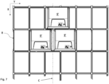
- grid cell 14 in the middle of the section of the illustrated grid system, comprises a grid opening/grid cell opening 15.
- an adjacent grid cell 14E comprising a grid opening 15E.
- a footprint 30 of a prior art container handling vehicle is schematically illustrated.
- the footprint 30 is defined by the horizontal extent of the wheels of the vehicle.
- the footprint 30 has a horizontal extent which is less than the horizontal extent of a grid cell.
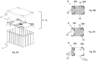
- Fig. 5A is a perspective side view of parts of a lifting device 18 which can be mounted in a container handling vehicle and a container 6 to be lifted by the lifting device.
- the lifting device comprises a lifting frame 17, which is commonly connected to at least one rotatable lifting shaft via lifting bands, the lifting shaft arranged at an upper level within a cavity of the container handling vehicle.
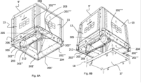
- Fig. 5B shows the footprint, i.e. the dashed area in the Figure denoted FV, of an exemplary container handling vehicle 9'according to the invention.
- the footprint FV is equal to the lateral extent of the container handling vehicle 9' in both directions.
- the container handling vehicle 9' consists of a first section 204 and a second section 205.
- Fig. 5C shows the footprint of the first section 204, i.e. the dashed area in the Figure denoted F1.
- the first section comprises a cavity for accommodating a storage bin 6 and a lifting device 18 as shown in Fig. 5A .
- Fig. 5D shows the footprint of the second section 205, i.e. the dashed area in the Figure denoted F2.
- Fig. 6A is a perspective side view from above of a container handling vehicle 9'.
- the container handling vehicle 9' operates on a rail system 8, and is configured to move laterally in the X and Y directions indicated in the Figure.
- the X direction is perpendicular to the Y direction.
- the vehicle 9' comprises a first set of wheels (not shown, see Fig. 8A ) arranged at opposite portions of a vehicle body 13, for moving the vehicle 9' along a first direction X on a rail system 8 of a storage system 1, and a second set of wheels (only two of the wheels of the second set of wheels are shown, 202",202"") arranged at opposite portions of the vehicle body 13, for moving the vehicle 9' along a second direction Y on the rail system 8.
- the second direction Y is perpendicular to the first direction X.
- the first set of wheels is displaceable in a vertical direction Z between a first position and a second position.
- the first set of wheels In the first position, the first set of wheels allow movement of the vehicle 9' along the first direction X, and in the second position, the second set of wheels allow movement of the vehicle 9' along the second direction Y.
- Structural details of suitable assemblies for providing displaceable sets of wheels are disclosed in for instance WO2015/193278 A1 and WO2017/153583 .
- Fig. 6B is a top view of a container handling vehicle 9' of Fig. 6A and illustrates the extent in the X- and Y directions (LX and LY) of the container handling vehicle 9' on a rail system 8.
- the line C indicates a center line of the grid cell 14 and grid cell opening 15 in the Y direction.
- the footprint of the container handling vehicle 9' in the X direction (LX) is substantially equal to the dimension of the grid cell 14 in the X direction and the footprint of the container handling vehicle 9' in the Y direction (line LY) is larger than the dimension of the grid cell 14 in the Y direction such that part of the vehicle body extends into a neighboring cell (in the embodiment shown, this is a neighbouring cell to the left of the cell being worked).
- This extension of the vehicle body into the neighboring cell is of a size less than half the lateral extent in the Y direction of the grid cell opening in the neighboring cell, meaning that the length LY is more than 1.0 grid cell but less than 1.5 grid cells 14 in the Y direction (1.0 ⁇ LY ⁇ 1.5 grid cells).
- the footprint of the container handling vehicle 9' is substantially square because the extent of the grid cell 14 is longer in the X direction than in the Y direction and the container handling vehicle occupies more than one grid cell 14 in the Y direction and only one grid cell 14 in the X direction.
- a substantially square footprint has the advantage that the overall stability of vehicle 9' is improved compared to prior art solutions displaying a more rectangular footprint often in combination with a relatively high center of gravity.
- Fig. 7 is a top view of three similar container handling vehicles 9' oriented in the same direction, passing each other and operating on a rail system 8 featuring dual-track rails as discussed above.
- the container handling vehicles 9' have a footprint corresponding to the dimension of the grid cell 14 in the X direction allowing other container handling vehicles 9' travelling in the Y direction, to pass in neighboring cells (the container handling vehicles 9' occupying two rows of the rail system 8 as they pass by each other) on both sides of the vehicle 9'.
- the size of the overlap into the neighboring cell is less than half the lateral extent of the grid cell in the Y direction, similar container handling vehicles 9' travelling in the X direction can pass each other occupying three rows.
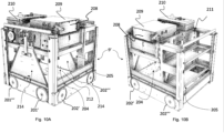
- the presence of the second section 205 makes it possible to utilize larger and stronger motors 203, see fig. 8A , for driving the wheels than in the prior art single cell robot shown in fig. 2A , while at the same time keeping many of the advantages of such a robot.
- the first section 204 accommodates a first 201', second 201", third 201 "'and fourth 201"" wheel of the first set of wheels and a first 202' and second 202" wheel of the second set of wheels
- the second section accommodates a third 202′′′ and fourth 202 ⁇ wheel of the second set of wheels.
- This particular wheel arrangement is highly advantageous as it allows for the use of more powerful wheel hub motors 203 for driving the second 201" and the fourth 201 ⁇ wheel of the first set of wheels as well as the third 202′′′ fourth 202 ⁇ wheel of the second set of wheels.
- the second 201" and fourth 201"" wheel of the first set of wheels can be accommodated in the second section (not shown) provided the hub motors of said wheels are also arranged in the second section.
- the rim of the wheels 201', 201′′′, 202', 202", 202′′′, 202 ⁇ preferably extend to the corners of the vehicle 9'.
- All of the wheels 201', 201", 201′′′, 201 ⁇ , 202', 202′′′, 202 ⁇ are preferably arranged inside the lateral extent LX, LY in the X and Y directions of the vehicle body 13 (see also description in relation to Fig. 9 ).
- the first section 204 and the second section 205 may be fully separated by a physical barrier at the intersection between the first and second sections 204, 205, such as a wall or plate or similar.
- the first and second sections 204, 205 may be partly separated at the intersection between the first and second section 204, 205, for example by providing a barrier over parts of the intersection.
- the first and second section is separated by a wheel connecting element 212 (i.e. a connection plate or beam) to which the second 201" and the fourth 201 ⁇ wheel of the first set of wheels and their respective hub motors 203 are connected...
- the wheel connecting element 212 is part of a wheel displacement assembly 214, such that the second 201" and the fourth 201 ⁇ wheel of the first set of wheels (together with the the first 201' and the third 201" wheel of the first set of wheels) may be moved in a vertical direction.
- the second 201" and the fourth 201"" wheels are accommodated in the first section 204, while the hub motors 203 extend into the second section.
- both the second 201" and the fourth 201"" wheels, as well as the hub motors may be accommodated in the second section 205.
- the second 201" and the fourth 201 ⁇ wheel of the first set of wheels, as well as the third 202′′′ fourth 202 ⁇ wheel of the second set of wheels, arranged such that their hub motors 203 extend/protrude into the second section 205 allows for the use of more powerful motors than would be the case if the hub motors were arranged such that they would extend into the first section 204.
- the remaining wheels, i.e. the wheels not featuring a hub motor extending into the second section may either be passive or motorized, for instance motorized by in-wheel hub motors as disclosed in WO 2016/120075 A1 .
- Fig. 8B is a perspective view from below of an interior of the container handling vehicle 9' showing the lifting frame 17 of the lifting device 18 in a lower position extending downwardly from the first section 204.
- the lifting device 18 may have similar features as the lifting device described in relation to Figs. 2A and 2B .
- Fig. 9 is a side view of a container handling vehicle with hub motors 203 and two batteries 213', 213" arranged in the second section 205.
- the exterior facing side of the wheels may in one aspect be arranged such that they are not extending outside the vehicle body 13 (indicated by the dotted lines on each side of the vehicle 9' in Fig. 9 ).
- the exterior facing sides of the wheels in the lateral X and Y directions may be flush with the vehicle body 13.
- the wheels in the opposite direction (X) i.e. those wheels may also be arranged such that they are not extending outside the vehicle body 13.
- the vehicle body 13 includes any of the following elements, even if all are present or if some are missing, such as body frame, side cover panels or plates, wheel suspensions, housing for track sensors between the wheels etc.
- a rotating exterior surface of the wheels may thus be arranged in the same vertical plane as one of the walls in the vehicle body 13.
- the wheels may be arranged inside the vehicle body 13 such that the rotating exterior surfaces of the wheels can be laterally displaced relative a vertical plane formed by one of the walls in the vehicle body 13.
- Fig. 6B none of the wheels are visible in the top view, indicating that the outermost lateral parts of all wheels are arranged such that they are not extending outside the vehicle body 13.
- the container handling vehicle 9' may be provided with an interface 206 (see Fig. 8A ) for charging of the batteries 213', 213" in the container handling vehicle 9'.
- Fig. 10A is a side view of a container handling vehicle 9' where certain parts like the covers are removed.
- the container handling vehicle 9' has an exchangeable battery 208 arranged inside a battery receiving unit 209 in an upper portion of the container handling vehicle.
- a controller unit 210 which communicates with the overall control system.
- the controller unit 210 may further accommodate a capacitor power supply (not shown).
- the capacitor power supply typically has the ability to store enough power to operate any of the electrically driven components of the vehicle 9' if the main power supply malfunctions or is lost. Such situations may e.g. be when the battery 208 is to be exchanged.
- the battery exchange is typically taking place on two different locations, i.e.
- the capacitor power supply may be used to move the robot between the two different locations.
- the capacitor power supply can be used to operate the lifting device and/or move the robot to a service area.
- any regenerated power can be supplied to the capacitor power supply in order to make sure that the capacitor power supply has sufficient power capacity to perform any of its desired functions.
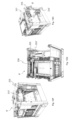
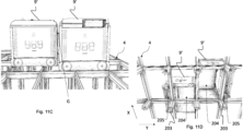
- Fig. 10B is another view of Fig. 10A , where it is disclosed an assembly of motors comprising a lifting device motor 211 arranged in the second section 205.
- the lifting device motor 211 is connected at one end of a rotatable lifting shaft (not shown) of a lifting device arranged in the first section.
- This lifting device motor 211 may replace other lifting device motor(s) (not shown) arranged in the first section or function as an auxiliary motor in addition to any lifting device motors arranged in the first section.
- the second section 205 makes it possible to reduce the number of lifting device motor(s) in the first section to a minimum (even avoid the use of a lifting device motor in the first section) because the size and lifting capacity of the lifting device motor 211 arranged in the second section 205 is not limited by the available space of the first section.
- the lifting device motor 211 in the second section may be the sole lifting device motor of the vehicle, such that the available space in a top section of the first section of the vehicle 9' is increased, or the motor 211 may be an auxiliary motor providing an increased lifting capacity to the lifting device.
- Fig. 10C shows an embodiment of a container handling vehicle 9', wherein the lifting device comprises a single lifting device motor 211' and angled transmission 215 are arranged in the second section.
- the embodiment serves to illustrate how the available space of the second section allows for the use of a more powerful (and consequently larger) lifting device motor 211' than what would be possible to arrange in the first section alone. This allows for the use of storage containers having a higher total weight (i.e. the weight including products stored in the container).
- the prior art vehicle in Fig. 2B and 2C would likely have available space for a similar large lifting device motor, but would not be able to fully utilize the possibility of increased lifting capacity due to the cantilever design. Again referring to Fig.
- the angled transmission 215 with connected lifting device motor 211' is angled downwards (i.e. in a mainly vertical direction).
- Figs 10D and 10E a similar embodiment as in Fig. 10C is shown, however, the angled transmission 215 with connected lifting device motor 211' is angled sideways (i.e. in a mainly horizontal direction), rotated 90 degrees relative to the embodiment in Fig 10C .
- Fig. 10E shows the lifting device axle 216 to which axle lifting bands connected to the lifting device 18 (not shown in Fig. 10E ) are connected and coils up and reels out during lifting and lowering of the lifting device.
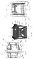
- Figs. 10F and 10G are perspective views of an alternative container handling vehicle of Fig. 10B , where the lifting device motor 211' and a hollow shaft gear 215 are arranged in the second section.
- the configuration of the lifting device motor 211' in Figs. 10B and 10C render possible the use of two lifting device motors 211, 211' connected to respective lifting axles 216 (only one lifting axle shown in the Figures).
- Such a setup i.e. two lifting device motors 211, 211' arranged at opposite sides in the second section will provide a more stable container handling vehicle 9' as the weight distribution from the lifting device motors 211, 211' will be more advantageous in terms of the overall centre of gravity for the container handling vehicle 9'.
- Fig 10H is an exploded view of a hollow shaft gear 215 used to connect the lifting device motor 211' and lifting device axle 216.
- the lifting axle 217 of Figs. 10F-10H has been extended and the gear 215 is connected directly to the extended lifting axle 217 without a dedicated connection.
- a hollow shaft gear 215 is used instead of an angled transmission.
- the hollow shaft gear 215 can be secured to the extended lifting axle 217 using dedicated means, such as e.g. as shown in the Figure where a clamp and wedge configuration is used.
- Fig. 10I is a side view of a container handling vehicle 9' with wheel motors 203 on the wheels 202′′′, 202 ⁇ in the Y direction in the second section 205 and not on the wheels 201", 201 ⁇ in the X direction on the separation element 212.
- Fig. 10J is a view from below a container handling vehicle 9' showing larger wheel motors 203 only on the wheels 202'", 202"" in the Y direction in the second section 205 and not on the wheels 201", 201"" in the X direction on the separation element 212.
- the separation element 212 of the first section 204 divides the interior of the container handling vehicle 9' in the first and second sections 204, 205.
- Two wheels 201", 201 ⁇ in the X direction are mounted on the separation element 212.
- Fig. 10K is a side view into the second section in an Y direction of the container handling vehicle 9'.
- the second section 205 is relatively smaller, i.e. less deep, than the second section 205 in e.g. Figs 10F-H .
- the first section 204 is of the same size as the first section 204 of the container handling vehicle 9' in e.g. Figs. 10F-10H and the second section 205 is smaller, i.e. it is less deep and has a relatively smaller extent in the Y direction, than the second section 205 of the container handling vehicle 9' in Figs. 10F-10H .
- the setup and relatively small size (i.e. small extent in the Y direction) of the second section 205 in Figs. 10I-10K has an advantage in that the cantilever or overhang formed of the second section 205 when the container handling vehicle is running in the X direction has minimum impact on the stability of the container handling vehicle 9'.
- the radial and longitudinal extent of the wheel motors 203 in the second sections are adapted to fit into the available internal space in the X direction and Y direction of the second section 205. As shown in Figs. 10I-10K , the radial/diameter extent of the wheel motors 203 are dictated by the extent of the second section in the Y direction (limited by the separation element between the first and second section 204, 205 and the vehicle body 13. The wheel motors 203 extend into an internal space in the second section 205, which internal space is delimited by the separation element 212 and the three sides of the vehicle body 13 forming three of the outer boundaries for the second section 205. The depth of the wheel motors 203 (i.e.
- the extent of the wheel motors 203 in the X direction) is limited by the width LX in the X direction and can be significantly larger than the width LY of the second section 205 in the Y direction, for example up to 50% larger and more, such as 60%, 70%, 80 and up to 90% larger.
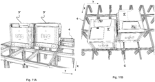
- Fig. 11A is a side view of two container handling vehicles 9' travelling in the X direction of the rail system 8 passing each other using a total of three cells in the Y direction of the rail system 8.
- This particular rail system comprises single track rails in the X direction and double-track rails in the Y direction.
- the combination of single- and double-track rails may in some instances be the most cost-efficient solution, even if a rail system using only double-track rails is optimal regarding the possible travel paths of the container-handling vehicles arranged thereon.
- Fig. 11B is a top view of Fig. 11A showing a gap G between the vehicle bodies 13 in the Y direction rendering possible the two vehicles 9' travelling in the X direction to occupy only three rows in the Y direction.
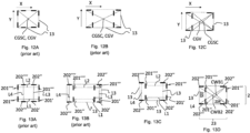
- Figs. 12A-C show differences in the center of gravity of the storage containers inside the storage container cavity relative the center of the footprint of the vehicle body, where Fig. 12A illustrates a prior art single cell robot, Fig. 12B is a prior art central cavity robot, and Fig. 12C shows an exemplary container handling vehicle according to the present invention.
- the center of gravity of the storage container CGSC is in the center of the cavity which also coincides with the center of the footprint of the vehicle body CGV.
- the center of gravity of storage container CGSC is in the center of the cavity which also coincides with the center of the footprint of the vehicle body CGV.
- Fig. 12C shows an exemplary container handling vehicle according to the present invention, where the center of gravity of storage container CGSC is displaced relative the center of the footprint of the vehicle body CGV.
- Figs. 13A-C are plan views showing differences in imaginary lines extending between wheel pairs of the same sets of wheels, and how said lines intersect, or not, imaginary lines between other wheels.
- Fig. 13A illustrates a prior art single cell robot
- Fig. 13B is a prior art central cavity robot
- Fig. 13C shows an exemplary container handling vehicle according to the present invention.
- each imaginary line L1, L2, L3, L4 extending between each of two pairs of opposed wheels in each set of wheels intersects two other imaginary lines L1, L2, L3, L4.
- Fig. 13C shows an exemplary container handling vehicle according to the present invention where imaginary lines L1, L2 between each of two pairs of opposed wheels in the first set of wheels intersect one imaginary line L3 extending between two wheels in the second set of wheels, and where one imaginary line L4 between two wheels in the second set of wheels does not intersect any imaginary lines.
- Fig. 13D shows a possible setup of centres of wheel bases for the first set of wheels and the second set of wheels, respectively, and that said wheel bases are off-centre relative each other.
- the wheel base of the first set of wheels 22 (comprising two wheel pairs where a first wheel pair comprises wheels denoted 201', 201" and a second wheel pair comprises wheels 201′′′ and 201 ⁇ ) has a centre CWB1 and the wheel base of the second set of wheels 23 (comprising two wheel pairs where a first wheel pair comprises opposite wheels denoted 202', 202" and a second wheel pair comprises opposite wheels 202′′′ and 202 ⁇ ) has a centre CWB2.
- the wheels 201'-201 ⁇ in the first set of wheels 22 are arranged on opposite sides of the first section 204 and the wheels 202'-202 ⁇ in the second set of wheels 23 are arranged on opposite sides of the vehicle body 13.
- the centre CWB2 of the second set of wheels 23 coincides with the centre of the vehicle body 13.
- the first set of wheels 22 comprises four wheels 201',201",201'",201"" in total.
- the four wheels 201 ',201",201′′′,201 ⁇ in the first set of wheels 22 are arranged as two pairs of wheel for movement in the X direction, where the wheels 201',201";201′′′,201 ⁇ of each pair are arranged on opposite sides of the first section 204.
- the second set of wheels 23 comprises four wheels 202',202",202′′′,202 ⁇ in total.
- the four wheels 202',202",202′′′,202 ⁇ are arranged as two pairs of wheels in the Y direction, where the wheels 202',202";202′′′,202 ⁇ of each pair are arranged on opposite sides of the vehicle body 13 (which may also be on opposite sides of the first section).
Landscapes
- Engineering & Computer Science (AREA)
- Mechanical Engineering (AREA)
- Physics & Mathematics (AREA)
- Mathematical Physics (AREA)
- Warehouses Or Storage Devices (AREA)
Claims (12)
- Behälterhandhabungsfahrzeug (9') zum Aufnehmen von Lagerbehältern (6) aus einem dreidimensionalen Raster (4) eines darunterliegenden Lagersystems (1), umfassend- einen ersten Satz von Rädern (22), angeordnet an einander gegenüberliegenden Teilen einer Fahrzeugkarosserie (13) des Behälterhandhabungsfahrzeugs (9'), zum Bewegen des Fahrzeugs (9') entlang einer ersten Richtung (X) auf einem Schienensystem (8) des Rasters (4); und- einen zweiten Satz von Rädern (23), angeordnet an einander gegenüberliegenden Teilen der Fahrzeugkarosserie (13), zum Bewegen des Fahrzeugs (9') entlang einer zweiten Richtung (Y) auf dem Schienensystem (8) des Rasters (4), wobei die zweite Richtung (Y) senkrecht zur ersten Richtung (X) ist;wobei
die Fahrzeugkarosserie (13) Wände auf allen Seiten umfasst, die eine Grundfläche (FV) bilden, definiert durch horizontale Peripherien in den ersten und zweiten Richtungen (X,Y) der Fahrzeugkarosserie (13), und wobei das Behälterhandhabungsfahrzeug (9') ferner Folgendes umfasst:- einen ersten Abschnitt (204) und einen zweiten Abschnitt (205), nebeneinander angeordnet, sodass ein Mittelpunkt einer Grundfläche (F1) des ersten Abschnitts (204) außermittig relativ zu einem Mittelpunkt (CGV) der Grundfläche (FV) der Fahrzeugkarosserie (13) angeordnet ist, und- wobei ein Größenverhältnis der Grundfläche (F1) des ersten Abschnitts (204) relativ zu einer Grundfläche (F2) des zweiten Abschnitts (205) mindestens 2:1 ist, und wobei- der erste Abschnitt (204) dazu ausgelegt ist, einen Lagerbehälter (6) aufzunehmen,- der zweite Abschnitt (205) eine Anordnung von Motoren zum Antreiben zumindest eines Rades (201',201",201‴,201ʺʺ,202',202",202‴,202ʺʺ) jedes der Sätze von Rädern (22,23) umfasst. - Behälterhandhabungsfahrzeug (9') nach Anspruch 1, wobei eine Gesamtfläche der ersten und der zweiten Grundflächen (F1,F2) gleich einer Gesamtfläche der Fahrzeugkarosseriegrundfläche (FV) ist.
- Behälterhandhabungsfahrzeug (9') nach Anspruch 2, wobei die ersten und zweiten Abschnitte (204,205) durch ein Trennelement (212) des ersten Abschnitts (204) getrennt sind.
- Behälterhandhabungsfahrzeug (9') nach einem der vorhergehenden Ansprüche, wobei die Wände im Wesentlichen vertikal sind.
- Behälterhandhabungsfahrzeug (9') nach einem der vorhergehenden Ansprüche, wobei die Anordnung von Motoren (203) zumindest einen ersten Motor (203) zum Antreiben des ersten Satzes von Rädern (22) und zumindest einen zweiten Motor (203) zum Antreiben des zweiten Satzes von Rädern (23) umfasst.
- Behälterhandhabungsfahrzeug (9') nach einem der vorhergehenden Ansprüche, wobei der erste Abschnitt (204) einen Hohlraum (21) zum Aufnehmen eines Lagerbehälters (6) und eine Hubvorrichtung (18), angeordnet an einem oberen Abschnitt oder einer oberen Ebene des Hohlraums (21), umfasst, wobei die Hubvorrichtung (18) dient zum Aufnehmen von Lagerbehältern (6) vom dreidimensionalen Raster (4) und wobei die Anordnung von Motoren (203) einen Hubvorrichtungsmotor (211,211') umfasst, der mit der Hubvorrichtung (18) verbunden ist.
- Behälterhandhabungsfahrzeug (9') nach einem der vorhergehenden Ansprüche, wobei der erste Satz von Rädern (22) in einer vertikalen Richtung zwischen einer ersten Position, in der der erste Satz von Rädern (22) Bewegung des Fahrzeugs (9') entlang der ersten Richtung (X) erlaubt, und einer zweiten Position, in der der zweite Satz von Rädern (23) Bewegung des Fahrzeugs (9') entlang der zweiten Richtung (23) erlaubt, versetzbar ist.
- Behälterhandhabungsfahrzeug (9') nach einem der vorhergehenden Ansprüche, wobei der erste Abschnitt (204) ein erstes (201') und drittes (201‴) Rad des ersten Satzes von Rädern (22) und ein erstes (202') und zweites (202") Rad des zweiten Satzes von Rädern (23) aufnimmt und der zweite Abschnitt (205) ein zweites (201") und ein viertes (201ʺʺ) Rad des ersten Satzes von Rädern (22) und ein drittes (202‴) und ein viertes (202ʺʺ) Rad des zweiten Satzes von Rädern (23) aufnimmt.
- Behälterhandhabungsfahrzeug (9') nach Anspruch 8, wobei der erste Abschnitt (204) vier Ecken umfasst, und wobei sich Ränder des ersten (201'), zweiten (201''), dritten (201‴) und vierten (201ʺʺ) Rades des ersten Satzes von Rädern (22) und des ersten (202') und zweiten (202") Rades des zweiten Satzes von Rädern (23) in die Ecken des ersten Abschnitts (204) erstrecken können.
- Behälterhandhabungsfahrzeug (9') nach einem der vorhergehenden Ansprüche, umfassend eine Batterie (213'), angeordnet im zweiten Abschnitt (205).
- Automatisiertes Lager- und Entnahmesystem, umfassend ein dreidimensionales Raster (4) und wenigstens ein Behälterhandhabungsfahrzeug (9') nach einem der vorhergehenden Ansprüche 1-10, wobei das Raster (4) ein Schienensystem (8), auf dem sich das Behälterhandhabungsfahrzeug (9')bewegen kann, und eine Vielzahl von Stapeln (7) von Lagerbehältern (7) umfasst;- wobei das Schienensystem (8) einen ersten Satz von parallelen Bahnen (10), die in einer horizontalen Ebene (P) angeordnet sind und in einer ersten Richtung (X) verlaufen, und einen zweiten Satz von parallelen Bahnen (11), die in der horizontalen Ebene (P) angeordnet sind und in einer zweiten Richtung (Y) verlaufen, die zu der ersten Richtung (X) senkrecht ist, umfasst, wobei der erste und der zweite Satz von Bahnen (10,11) eine Rasterstruktur in der horizontalen Ebene (P) bilden, die eine Vielzahl von angrenzenden Rasterzellen (14) umfasst, wobei jede Rasterzelle eine Rasteröffnung (15) umfasst, die von einem Paar von gegenüberliegenden Bahnen (10a,10b) des ersten Satzes von Bahnen (10) und einem Paar von gegenüberliegenden Bahnen (10a,10b) des zweiten Satzes von Bahnen (11) definiert wird;- wobei die Vielzahl von Stapeln (7) von Lagerbehältern (6) in Lagersäulen (5) angeordnet sind, die unterhalb des Schienensystems (8) angeordnet sind, wobei jede Lagersäule (5) vertikal unter einer Rasteröffnung (15) angeordnet ist;- wobei die erste Grundfläche (F1) im Wesentlichen gleich einer Rasterzelle (14) ist, die von einer Querschnittsfläche zwischen einem Paar von gegenüberliegenden Bahnen (10a,10b) des ersten Satzes von Bahnen (10) und einem Paar von gegenüberliegenden Bahnen (10a,10b) des zweiten Satzes von Bahnen (11), einschließlich der Breite der Bahnen, definiert wird, und wobei sich der zweite Abschnitt (205) teilweise in eine benachbarte Rasteröffnung (15) erstreckt, wenn der erste Abschnitt (204) über einer angrenzenden Rasteröffnung positioniert ist.
- Automatisiertes Lager- und Entnahmesystem gemäß Anspruch 11, wobei eine Größe der Grundfläche (FV) des Behälterhandhabungsfahrzeugs (9') in der ersten Richtung (X), LX, und der zweiten Richtung (Y), LY, beträgt:- LX = 1,0 Rasterzelle (14) in der ersten Richtung (X), und- 1 < LY < 1,5 Rasterzellen (14) in der zweiten Richtung (Y),wobei eine Rasterzelle (14) als die Querschnittsfläche zwischen dem Mittelpunkt von zwei Schienen, die in der ersten Richtung (X) verlaufen, und dem Mittelpunkt von zwei Schienen, die in der zweiten Richtung (Y) verlaufen, einschließlich der Breite der Bahnen, definiert ist.
Priority Applications (1)
| Application Number | Priority Date | Filing Date | Title |
|---|---|---|---|
| EP24198306.3A EP4480861A3 (de) | 2018-04-25 | 2019-02-14 | Containerhandhabungsfahrzeug mit einem ersten und einem zweiten abschnitt und einer anordnung von motoren in einem zweiten abschnitt zum antreiben mindestens eines rades eines jeden radsatzes |
Applications Claiming Priority (8)
| Application Number | Priority Date | Filing Date | Title |
|---|---|---|---|
| NO20180589A NO344970B1 (en) | 2018-04-25 | 2018-04-25 | Container-handling vehicle comprising a lifting device and method of raising or lowering a storage container relative a container-handling vehicle having a lifting device |
| NO20180590A NO346347B1 (en) | 2018-04-25 | 2018-04-25 | Container handling vehicle comprising first and second section and assembly of motors in second section, and system |
| NO20180591A NO346364B1 (en) | 2018-04-25 | 2018-04-25 | Container handling vehicle with first and second sections and battery in second section, and system. |
| PCT/EP2018/077732 WO2019206440A1 (en) | 2018-04-25 | 2018-10-11 | Container handling vehicle with first and second sections and with battery in second section |
| PCT/EP2018/077713 WO2019206439A1 (en) | 2018-04-25 | 2018-10-11 | Container handling vehicle with first and second sections with motor in second section |
| PCT/EP2018/077687 WO2019206437A1 (en) | 2018-04-25 | 2018-10-11 | Container-handling vehicle |
| EP19703761.7A EP3784603B1 (de) | 2018-04-25 | 2019-02-14 | Containerhandhabungsfahrzeug mit ersten und zweiten abschnitten und grösseren radmotoren auf zwei der räder im zweiten abschnitt |
| PCT/EP2019/053681 WO2019206488A1 (en) | 2018-04-25 | 2019-02-14 | Container handling vehicle with first and second sections and larger wheel motors on two of the wheels in the second section |
Related Parent Applications (2)
| Application Number | Title | Priority Date | Filing Date |
|---|---|---|---|
| EP19703761.7A Division-Into EP3784603B1 (de) | 2018-04-25 | 2019-02-14 | Containerhandhabungsfahrzeug mit ersten und zweiten abschnitten und grösseren radmotoren auf zwei der räder im zweiten abschnitt |
| EP19703761.7A Division EP3784603B1 (de) | 2018-04-25 | 2019-02-14 | Containerhandhabungsfahrzeug mit ersten und zweiten abschnitten und grösseren radmotoren auf zwei der räder im zweiten abschnitt |
Related Child Applications (1)
| Application Number | Title | Priority Date | Filing Date |
|---|---|---|---|
| EP24198306.3A Division EP4480861A3 (de) | 2018-04-25 | 2019-02-14 | Containerhandhabungsfahrzeug mit einem ersten und einem zweiten abschnitt und einer anordnung von motoren in einem zweiten abschnitt zum antreiben mindestens eines rades eines jeden radsatzes |
Publications (3)
| Publication Number | Publication Date |
|---|---|
| EP4011806A1 EP4011806A1 (de) | 2022-06-15 |
| EP4011806C0 EP4011806C0 (de) | 2024-09-04 |
| EP4011806B1 true EP4011806B1 (de) | 2024-09-04 |
Family
ID=72896210
Family Applications (4)
| Application Number | Title | Priority Date | Filing Date |
|---|---|---|---|
| EP24169303.5A Pending EP4484336A1 (de) | 2018-04-25 | 2019-02-14 | Containerhandhabungsfahrzeug mit ersten und zweiten abschnitten und hebevorrichtungsmotor in zweitem abschnitt |
| EP22154825.8A Active EP4011806B1 (de) | 2018-04-25 | 2019-02-14 | Containerhandhabungsfahrzeug mit einem ersten und einem zweiten abschnitt und einer anordnung von motoren in einem zweiten abschnitt zum antreiben mindestens eines rades eines jeden radsatzes |
| EP24198306.3A Pending EP4480861A3 (de) | 2018-04-25 | 2019-02-14 | Containerhandhabungsfahrzeug mit einem ersten und einem zweiten abschnitt und einer anordnung von motoren in einem zweiten abschnitt zum antreiben mindestens eines rades eines jeden radsatzes |
| EP19703759.1A Active EP3784602B1 (de) | 2018-04-25 | 2019-02-14 | Containerhandhabungsfahrzeug mit ersten und zweiten abschnitten und hebevorrichtungsmotor in zweitem abschnitt |
Family Applications Before (1)
| Application Number | Title | Priority Date | Filing Date |
|---|---|---|---|
| EP24169303.5A Pending EP4484336A1 (de) | 2018-04-25 | 2019-02-14 | Containerhandhabungsfahrzeug mit ersten und zweiten abschnitten und hebevorrichtungsmotor in zweitem abschnitt |
Family Applications After (2)
| Application Number | Title | Priority Date | Filing Date |
|---|---|---|---|
| EP24198306.3A Pending EP4480861A3 (de) | 2018-04-25 | 2019-02-14 | Containerhandhabungsfahrzeug mit einem ersten und einem zweiten abschnitt und einer anordnung von motoren in einem zweiten abschnitt zum antreiben mindestens eines rades eines jeden radsatzes |
| EP19703759.1A Active EP3784602B1 (de) | 2018-04-25 | 2019-02-14 | Containerhandhabungsfahrzeug mit ersten und zweiten abschnitten und hebevorrichtungsmotor in zweitem abschnitt |
Country Status (9)
| Country | Link |
|---|---|
| US (8) | US11377298B2 (de) |
| EP (4) | EP4484336A1 (de) |
| JP (6) | JP7304893B2 (de) |
| CN (4) | CN112041245B (de) |
| CA (2) | CA3095688A1 (de) |
| DK (1) | DK3784603T3 (de) |
| ES (3) | ES2980146T3 (de) |
| PL (3) | PL3784603T3 (de) |
| WO (1) | WO2019206487A1 (de) |
Families Citing this family (212)
| Publication number | Priority date | Publication date | Assignee | Title |
|---|---|---|---|---|
| DK3784603T3 (da) * | 2018-04-25 | 2022-05-16 | Autostore Tech As | Beholderhåndteringskøretøj med første og anden sektioner og større hjulmotorer på to af hjulene i den anden sektion |
| GB201903982D0 (en) * | 2019-03-22 | 2019-05-08 | Ocado Innovation Ltd | Load-handling device |
| GB202001012D0 (en) * | 2020-01-24 | 2020-03-11 | Ocado Innovation Ltd | Raising and lowering containers |
| CN113401548B (zh) | 2020-03-16 | 2023-07-11 | 因特利格雷特总部有限责任公司 | 用于多深度存放架的自动化穿梭车系统 |
| EP4211408B1 (de) | 2020-09-11 | 2025-11-26 | Autostore Technology AS | System zur temperatursteuerung in einem automatisierten lagersystem |
| EP4251545A1 (de) | 2020-11-30 | 2023-10-04 | Autostore Technology AS | Ferngesteuertes fahrzeug zur handhabung eines lagerbehälters auf einem schienensystem eines automatisierten regalbedienungssystems |
| NO346540B1 (en) | 2020-12-23 | 2022-09-26 | Autostore Tech As | An access station for an automated storage and retrieval system and method for using same |
| WO2022184472A1 (en) | 2021-03-01 | 2022-09-09 | Autostore Technology AS | An automated storage system |
| US20240167533A1 (en) | 2021-03-25 | 2024-05-23 | Autostore Technology AS | Bracing arrangement with damper |
| NO347583B1 (en) | 2021-03-25 | 2024-01-22 | Autostore Tech As | Bracing arrangement |
| NO348008B1 (en) | 2021-04-09 | 2024-06-17 | Autostore Tech As | Product handling system |
| US20240190652A1 (en) | 2021-04-09 | 2024-06-13 | Autostore Technology AS | A container handling vehicle for handling a delivery container stored within a storage container and a method thereof |
| NO20211040A1 (en) | 2021-04-09 | 2022-10-10 | Autostore Tech As | A container handling vehicle for handling a delivery container stored within a storage container and a method thereof. |
| NO20210494A1 (en) | 2021-04-20 | 2022-10-21 | Autostore Tech As | A Method and vehicle for rescuing a stalled container handling vehicle |
| NO347479B1 (en) | 2021-04-27 | 2023-11-20 | Autostore Tech As | A double ended access station for an automated storage and retrieval system and a method for using same |
| NO346814B1 (en) | 2021-04-28 | 2023-01-16 | Autostore Tech As | Container handler and method for handling a storage container |
| NO346975B1 (en) | 2021-05-21 | 2023-03-20 | Autostore Tech As | Automated storage and retrieval system comprising a transfer column with side opening with blocker and method of operating blocker |
| WO2022243153A1 (en) | 2021-05-21 | 2022-11-24 | Autostore Technology AS | A storage column module for coupling to a framework structure of an automated storage and retrieval system |
| NO20210679A1 (en) | 2021-05-28 | 2022-11-29 | Autostore Tech As | An automated storage and retrieval system with a dynamic storage section and a method of using same |
| NO346915B1 (en) | 2021-05-27 | 2023-02-27 | Autostore Tech As | Rail Joint |
| US20240278987A1 (en) | 2021-05-28 | 2024-08-22 | Autostore Technology AS | A remotely operated vehicle with top guiding and a method of using same |
| NO346798B1 (en) | 2021-05-28 | 2023-01-16 | Autostore Tech As | An assembly and a method for handling goods holders and an automated storage and retrieval system comprising said assembly |
| NO346980B1 (en) | 2021-06-04 | 2023-03-27 | Autostore Tech As | Service Vehicle Unit |
| NO346764B1 (en) | 2021-06-10 | 2022-12-19 | Autostore Tech As | A storage container for an automated, grid-based storage and retrieval system. |
| NO346930B1 (en) | 2021-06-30 | 2023-03-06 | Autostore Tech As | An access station for an automated storage and retrieval system, an automated storage and retrieval system comprising the access station and a method of using same |
| NO346982B1 (en) | 2021-06-30 | 2023-03-27 | Autostore Tech As | System, method and computer program product of determining a position of a container handling vehicle in an automated grid based storage and retrieval system |
| NO348514B1 (en) | 2021-06-30 | 2025-02-24 | Autostore Tech As | An access station for an automated storage and retrieval system and a method of presenting a goods holder at the access station |
| NO346963B1 (en) | 2021-08-23 | 2023-03-20 | Autostore Tech As | Disinfection station for a storage container |
| NO346957B1 (en) | 2021-08-27 | 2023-03-20 | Autostore Tech As | A gripper assembly |
| EP4144669A1 (de) | 2021-09-07 | 2023-03-08 | Autostore Technology AS | System und verfahren zur schwerkraftentladung von gegenständen aus einem behälter |
| NO347370B1 (en) | 2021-09-07 | 2023-10-02 | Autostore Tech As | Storage container for produce |
| NO347021B1 (en) | 2021-09-17 | 2023-04-17 | Autostore Tech As | Storage system |
| NO348060B1 (en) | 2021-09-17 | 2024-07-08 | Autostore Tech As | A container buffering assembly, a storage system comprising the container buffering assembly, and associated methods |
| NO347003B1 (en) | 2021-09-24 | 2023-04-03 | Autostore Tech As | Storage grid for vertical farming |
| NO347604B1 (en) | 2021-09-29 | 2024-01-29 | Autostore Tech As | A hatch assembly for a port of a storage and retrieval system and a method for controlling operation of the hatch assembly |
| NO20211238A1 (en) | 2021-10-13 | 2023-04-14 | Autostore Tech As | A delivery port for delivery of goods contained in goods holders |
| NO20211250A1 (en) | 2021-10-18 | 2023-04-19 | Autostore Tech As | A service vehicle for an automated storage and retrieval system |
| NO347132B1 (en) | 2021-10-19 | 2023-05-30 | Autostore Tech As | An assembly comprising a storage cell and a goods holder, a module comprising a plurality of the assemblies and a storage and retrieval system comprising the module |
| NO347078B1 (en) | 2021-10-25 | 2023-05-08 | Autostore Tech As | Access station safety mechanism |
| NO20211300A1 (en) | 2021-10-29 | 2023-05-01 | Autostore Tech As | Robotic container handler, an access and distribution station, a storage and retrieval system and a method thereof |
| NO347302B1 (en) | 2021-11-01 | 2023-09-04 | Autostore Tech As | Storage system |
| NO347123B1 (en) | 2021-11-10 | 2023-05-22 | Autostore Tech As | A vehicle-portable grid assessment device |
| NO347063B1 (en) | 2021-11-11 | 2023-05-02 | Autostore Tech As | Storage system comprising a vehicle gate arrangement, a vehicle gate arrangement and method of moving a vehicle |
| NO347126B1 (en) | 2021-11-16 | 2023-05-30 | Autostore Tech As | Lifting frame assembly with extendible and retractable guide members, container handling vehicle and storage system, and associated method. |
| NO347538B1 (en) | 2021-11-30 | 2023-12-18 | Autostore Tech As | A storage module for an automated storage and retrieval system and method for using same |
| NO347833B1 (en) | 2021-11-30 | 2024-04-15 | Autostore Tech As | A system for transporting a product item to an access station |
| NO20211460A1 (en) | 2021-12-03 | 2023-06-05 | Autostore Tech As | A levelling assembly for a storage and retrieval system |
| NO348892B1 (en) | 2021-12-13 | 2025-07-07 | Autostore Tech As | Method for delivering goods to a customer utilizing optical character recognition |
| NO20211507A1 (en) | 2021-12-14 | 2023-06-15 | Autostore Tech As | Buffer system for a station of a storage and retrieval system and method of using a buffer system at a station |
| US20250012504A1 (en) | 2021-12-15 | 2025-01-09 | Autostore Technology AS | An air flow control device, an automated storage and retrieval system comprising such a device and a method for thermally managing air in an automated, grid-based storage and retrieval system |
| NO347687B1 (en) | 2021-12-15 | 2024-02-19 | Autostore Tech As | System and method of temperature control in an automated grid based storage and retrieval system |
| NO20211521A1 (en) | 2021-12-16 | 2023-06-19 | Autostore Tech As | Crossing with thermal expansion joint for a rail-based grid and method providing a crossing |
| NO347201B1 (en) | 2021-12-17 | 2023-07-03 | Autostore Tech As | A method of operating an automated storage and retrieval system |
| NO346913B1 (en) | 2021-12-21 | 2023-02-27 | Autostore Tech As | Storage system for vertical farming and a method thereof |
| NO347211B1 (en) | 2021-12-21 | 2023-07-10 | Autostore Tech As | Trash handling arrangement for an automated storage system |
| US12115682B2 (en) * | 2021-12-28 | 2024-10-15 | 1Mrobotics Ltd. | Delivery station and method for autonomously storing and delivering goods |
| NO347235B1 (en) | 2022-01-07 | 2023-07-24 | Autostore Tech As | Variable temperature zone in a storage and retrieval system |
| NO347254B1 (en) | 2022-01-11 | 2023-08-14 | Autostore Tech As | Storage system |
| CN114523472B (zh) * | 2022-01-24 | 2023-05-23 | 湖南视比特机器人有限公司 | 一种工件协同抓取方法、系统及存储介质 |
| NO20220242A1 (en) | 2022-02-23 | 2023-08-24 | Autostore Tech As | Storage system comprising a framework adjuster |
| NO347574B1 (en) | 2022-02-28 | 2024-01-15 | Autostore Tech As | A device and a method for determining rotational position of a rotating shaft |
| NO347439B1 (en) * | 2022-03-08 | 2023-11-06 | Autostore Tech As | Container handling vehicle |
| CA3245354A1 (en) | 2022-03-08 | 2023-09-14 | Autostore Tech As | CONTAINER HANDLING VEHICLE |
| NO347587B1 (en) * | 2022-03-08 | 2024-01-22 | Autostore Tech As | A remotely operated vehicle, an automated storage and retrieval system and a method of operating a remotely operated vehicle for handling a goods holder of an automated storage and retrieval system |
| WO2023169987A1 (en) | 2022-03-08 | 2023-09-14 | Autostore Technology AS | Track sensor arrangement |
| NO347586B1 (en) | 2022-03-08 | 2024-01-22 | Autostore Tech As | A remotely operated vehicle, an automated storage and retrieval system and a method of driving a remotely operated vehicle for handling a goods holder of an automated storage and retrieval system |
| NO347658B1 (en) | 2022-03-15 | 2024-02-12 | Autostore Tech As | Service trolley, an automated storage and retrieval system comprising the trolley, and method of operating the trolley |
| NO347372B1 (en) | 2022-03-23 | 2023-10-02 | Autostore Tech As | A remotely operated vehicle for an automated storage and retrieval system |
| NO20220389A1 (en) | 2022-03-30 | 2023-10-02 | Autostore Tech As | Storage system with containers and access frames |
| NO347388B1 (en) | 2022-03-30 | 2023-10-09 | Autostore Tech As | Method, system and computer program product for determining a route for a container handling vehicle |
| NO347454B1 (en) | 2022-04-28 | 2023-11-06 | Autostore Tech As | A system, method and computer program product for rental of physical items |
| NO347554B1 (en) | 2022-04-29 | 2024-01-15 | Autostore Tech As | Conveyor access station for an automated storage and retrieval system and a method for using same |
| NO347584B1 (en) | 2022-04-29 | 2024-01-22 | Autostore Tech As | Two part storage container with an assembled configuration and a split configuration |
| NO347806B1 (en) | 2022-05-02 | 2024-03-25 | Autostore Tech As | Positioning tool |
| NO347763B1 (en) | 2022-05-03 | 2024-03-18 | Autostore Tech As | Local positioning system |
| NO20220504A1 (en) | 2022-05-03 | 2023-11-06 | Autostore Tech As | A container handler, a storage and retrieval system comprising the container handler and a method for handling a container by means of the container handler |
| NO20220560A1 (en) | 2022-05-11 | 2023-11-13 | Autostore Tech As | Container handling vehicle with all wheel drive in at least one direction, associated system and method of assembling |
| NO20220625A1 (en) | 2022-05-31 | 2023-12-01 | Autostore Tech As | Weighing method |
| NO20220692A1 (en) | 2022-06-17 | 2023-12-18 | Autostore Tech As | A method and a system for determining condition of a component of a remotely operated vehicle |
| NO20220709A1 (en) | 2022-06-21 | 2023-12-22 | Autostore Tech As | An access station for an automated storage and retrieval system |
| NO347558B1 (en) | 2022-06-29 | 2024-01-15 | Autostore Tech As | Container handling vehicle |
| NO20220739A1 (en) | 2022-06-29 | 2024-01-01 | Autostore Tech As | Container handling vehicle with motor at lower elevation than first and second lifting shafts, a system comprising the container handling vehicle, and method of driving the first and second lifting shafts |
| NO347700B1 (en) | 2022-06-29 | 2024-02-26 | Autostore Tech As | Rail vehicle |
| NO20220787A1 (en) | 2022-07-08 | 2024-01-09 | Autostore Tech As | Dynamic tuning of dig-down |
| NO20220878A1 (en) | 2022-08-12 | 2024-02-13 | Autostore Tech As | An automated storage and retrieval system having a container transfer apparatus, and a method thereof |
| NO347924B1 (en) | 2022-08-12 | 2024-05-13 | Autostore Tech As | An automated storage and retrieval system having a container transfer system and a method thereof |
| NO347713B1 (en) | 2022-08-25 | 2024-03-04 | Autostore Tech As | Batch picking interface |
| NO348719B1 (en) | 2022-08-29 | 2025-05-12 | Autostore Tech As | Storage system |
| NO347943B1 (en) | 2022-08-30 | 2024-05-21 | Autostore Tech As | An automated storage and retrieval system comprising a first type of container handling vehicle, a crane and a gantry arrangement, and a method of transferring a storage container |
| NO20220933A1 (en) | 2022-08-30 | 2024-03-01 | Autostore Tech As | A crane trolley assembly, a crane and a system comprisingthe assembly and associated methods |
| NO20220940A1 (en) | 2022-09-01 | 2024-03-04 | Autostore Tech As | System and method for rearranging containers in an automated storage and retrieval system |
| NO20220942A1 (en) | 2022-09-01 | 2024-03-04 | Autostore Tech As | System and method for controlling the movement of containers in an automated storage and retrieval system |
| NO347997B1 (en) | 2022-09-06 | 2024-06-10 | Autostore Tech As | A system and a method for extracting air from an evaporator unit associated with an automated storage and retrieval system |
| NO20221018A1 (en) | 2022-09-26 | 2024-03-27 | Autostore Tech As | Container handling vehicle |
| NO347911B1 (en) | 2022-09-26 | 2024-05-13 | Autostore Tech As | Access station |
| NO347993B1 (en) | 2022-09-27 | 2024-06-10 | Autostore Tech As | An automated storage and retrieval system comprising a temperature management system and a method for managing temperature in the automated storage and retrieval system |
| NO347948B1 (en) | 2022-09-29 | 2024-05-21 | Autostore Tech As | Buffer system |
| NO20221038A1 (en) | 2022-09-29 | 2024-04-01 | Autostore Tech As | An automated storage and retrieval system, a container transfer apparatus and a method thereof |
| NO347996B1 (en) * | 2022-10-11 | 2024-06-10 | Autostore Tech As | An assembly and a method for transferring a plurality of goods holders |
| NO20221114A1 (en) | 2022-10-18 | 2024-04-19 | Autostore Tech As | A container transport vehicle for with internal receiving space for receiving a storage container from another vehicle, associated system and methods |
| NO20221149A1 (en) | 2022-10-26 | 2024-04-29 | Autostore Tech As | Detachable sensor jig and method for predicting vehicle malfunction |
| NO20221150A1 (en) | 2022-10-26 | 2024-04-29 | Autostore Tech As | Sensor station and method for predicting vehicle malfunction |
| WO2024089150A1 (en) | 2022-10-28 | 2024-05-02 | Autostore Technology AS | Method for the stocking of goods in an automated storage and retrieval system |
| WO2024089149A1 (en) | 2022-10-28 | 2024-05-02 | Autostore Technology AS | A device and method for inserting of storage containers with temperature-sensitive goods into a temperature controlled section of an automated storage and retrieval system |
| NO347965B1 (en) | 2022-10-28 | 2024-06-03 | Autostore Tech As | A device and method for inserting storage containers into an automated storage and retrieval system |
| EP4365118A1 (de) | 2022-11-03 | 2024-05-08 | Autostore Technology AS | Warenhalterrotationsstation und verfahren zum extrahieren von waren aus einem warenhalter |
| NO347966B1 (en) | 2022-11-24 | 2024-06-03 | Autostore Tech As | Vertical farming system, a growth frame and framework structure for the vertical farming system, and a method of providing a root chamber in the vertical farming system |
| NO20221274A1 (en) | 2022-11-25 | 2024-05-27 | Autostore Tech As | A unit for moving a plurality of goods holders and a method of moving the plurality of goods holders |
| NO20221276A1 (en) | 2022-11-25 | 2024-05-27 | Autostore Tech As | An assembly for transporting a plurality of goods holders to/from a grid-based storage and retrieval system |
| NO20221281A1 (en) | 2022-11-29 | 2024-05-30 | Autostore Tech As | Automated storage and retrieval system with large-sized storage containers |
| NO348030B1 (en) | 2022-11-29 | 2024-06-24 | Autostore Tech As | Service vehicle with a center drive unit, system and method for operating service vehicle |
| NO20221302A1 (en) | 2022-12-05 | 2024-06-06 | Autostore Tech As | Lift arrangement and method for moving a storage container in a multi-framework storage system |
| EP4630126A1 (de) | 2022-12-09 | 2025-10-15 | AutoStore Technology AS | Klemme zur verankerung eines sicherheitsgurts an einem schienensystem und verfahren zur verwendung davon |
| NO348001B1 (en) | 2022-12-16 | 2024-06-17 | Autostore Tech As | A container transport vehicle, an automated storage and retrieval system and a method thereof |
| NO20221352A1 (en) | 2022-12-16 | 2024-06-17 | Autostore Tech As | An automated storage and retrieval system comprising a vehicle pen and a transport vehicle, and an associated methods |
| NO20221350A1 (en) | 2022-12-16 | 2024-06-17 | Autostore Tech As | An automated storage and retrieval system with logically operable barriers for safe enter and exit into a transport vehicle, and an associated method |
| EP4639296A1 (de) | 2022-12-19 | 2025-10-29 | Autostore Technology AS | Containerhandhabungsfahrzeug zur handhabung von kleineren lagerbehältern in einem automatisierten regalbedienungssystem |
| NO20221372A1 (en) | 2022-12-20 | 2024-06-21 | Autostore Tech As | System and maintenance for condition based maintenance of port |
| NO20221371A1 (en) | 2022-12-20 | 2024-06-21 | Autostore Tech As | System and maintenance for condition based maintenance of Port |
| NO20221374A1 (en) | 2022-12-20 | 2024-06-21 | Autostore Tech As | Service Vehicle |
| NO348016B1 (en) | 2022-12-20 | 2024-06-24 | Autostore Tech As | Container handling vehicle and storage system |
| NO348240B1 (en) | 2022-12-20 | 2024-10-21 | Autostore Tech As | System and method for weighing containers |
| NO20221378A1 (en) | 2022-12-21 | 2024-06-24 | Autostore Tech As | A remotely operated picking vehicle, an automated storage and retrieval system, and a method of using same |
| NO20221379A1 (en) | 2022-12-21 | 2024-06-24 | Autostore Tech As | Robotic picking and conveyor system |
| NO20221406A1 (en) | 2022-12-23 | 2024-06-24 | Autostore Tech As | Method, system and computer program product for moving a storage container |
| NO20221405A1 (en) | 2022-12-23 | 2024-06-24 | Autostore Tech As | A service vehicle and a method for retrieving a malfunctioning container handling vehicle |
| NO20221408A1 (en) | 2022-12-27 | 2024-06-28 | Autostore Tech As | Storage system |
| WO2024141364A1 (en) | 2022-12-27 | 2024-07-04 | Autostore Technology AS | A storage system for storage containers comprising a framework structure, stacker frames, storage containers, a stacker frame lifter and a container lifter |
| WO2024180088A1 (en) | 2023-02-27 | 2024-09-06 | Autostore Technology AS | Actuator for moving a storage container |
| NO20230191A1 (en) | 2023-02-27 | 2024-08-28 | Autostore Tech As | Access station for an automated storage and retrieval system |
| NO348171B1 (en) | 2023-03-06 | 2024-09-16 | Autostore Tech As | A method for adapting a goods holder and an adapter for a goods holder |
| NO348165B1 (en) | 2023-03-06 | 2024-09-16 | Autostore Tech As | An adapter for a goods holder for a remotely operated vehicle in a grid-based storage and retrieval system, including a system and method for using same |
| NO348183B1 (en) | 2023-03-14 | 2024-09-23 | Autostore Tech As | Storage system |
| NO348182B1 (en) | 2023-03-16 | 2024-09-23 | Autostore Tech As | A vertically displaceable lifting frame for transporting a goods holder to/from a storage volume of an automated storage and retrieval system |
| WO2024194481A1 (en) | 2023-03-22 | 2024-09-26 | Autostore Technology AS | Container transfer system |
| NO20230331A1 (en) | 2023-03-24 | 2024-09-25 | Autostore Tech As | Leveling device |
| NO348519B1 (en) | 2023-03-27 | 2025-02-24 | Autostore Tech As | Charging station service/inspection tool |
| WO2024200791A1 (en) | 2023-03-28 | 2024-10-03 | Autostore Technology AS | Storage system |
| WO2024200640A1 (en) | 2023-03-31 | 2024-10-03 | Autostore Technology AS | Spacer device for a stack of containers of a storage and retrieval system |
| NO348219B1 (en) | 2023-03-31 | 2024-10-07 | Autostore Tech As | Service device |
| WO2024227520A1 (en) | 2023-04-28 | 2024-11-07 | Autostore Technology AS | A remotely operated vehicle for handling a storage container |
| NO20230482A1 (en) | 2023-04-28 | 2024-10-29 | Autostore Tech As | Access station with stopper mechanism |
| NO20230487A1 (en) | 2023-04-28 | 2024-10-29 | Autostore Tech As | A rail system, particularly for an automated storage and retrieval system for storage and retrieval of containers |
| WO2024227628A1 (en) | 2023-05-02 | 2024-11-07 | Autostore Technology AS | Vertical roller conveyor |
| NO20230523A1 (en) | 2023-05-05 | 2024-11-06 | Autostore Tech As | A method for securing two vertically aligned, elongate members and a joining member-and-connector assembly |
| WO2024231194A1 (en) | 2023-05-05 | 2024-11-14 | Autostore Technology AS | A method for securing two upright members and a joining device-and-connector assembly |
| WO2024231287A1 (en) | 2023-05-05 | 2024-11-14 | Autostore Technology AS | Automated vehicle with directional antenna |
| NO348392B1 (en) | 2023-05-09 | 2025-01-06 | Autostore Tech As | Container handling vehicle for handling containers in an automated storage and retrieval system and an automated storage and retrieval system |
| WO2024231497A1 (en) | 2023-05-09 | 2024-11-14 | Autostore Technology AS | A set of storage containers |
| US12329079B2 (en) | 2023-05-12 | 2025-06-17 | Autostore Technology AS | Stackable growth module for supporting plants in a vertical farming system |
| US20240373805A1 (en) | 2023-05-12 | 2024-11-14 | Autostore Technology AS | Vertical farming watering system and method |
| US20240373806A1 (en) | 2023-05-12 | 2024-11-14 | Autostore Technology AS | Stackable lighting module |
| US20240373793A1 (en) | 2023-05-12 | 2024-11-14 | Autostore Technology AS | Modular vertical farming system |
| WO2024236056A1 (en) | 2023-05-15 | 2024-11-21 | Autostore Technology AS | Storage system comprising stack storage columns and shelf storage columns, and associated method |
| NO20230612A1 (en) | 2023-05-30 | 2024-12-02 | Autostore Tech As | Access station with light guides |
| NO20230614A1 (en) | 2023-05-30 | 2024-12-02 | Autostore Tech As | Robot Picking and conveyor on top of grid. |
| WO2024246282A1 (en) | 2023-05-31 | 2024-12-05 | Autostore Technology AS | Storage container with a cover and a seal |
| US20240400321A1 (en) | 2023-05-31 | 2024-12-05 | Autostore Technology AS | System for delivering storage containers |
| NO348399B1 (en) | 2023-06-01 | 2025-01-06 | Autostore Tech As | A container transfer station, a storage system and a method for buffering storage container in a storage system |
| NO20230646A1 (en) | 2023-06-06 | 2024-12-09 | Autostore Tech As | Container handling vehicle and storage system |
| WO2024251392A1 (en) | 2023-06-08 | 2024-12-12 | Autostore Technology AS | Method, system and computer program product for determining non-conflicting routes for container handling vehicles |
| WO2024256698A1 (en) | 2023-06-15 | 2024-12-19 | Autostore Technology AS | Grid connector |
| WO2024256038A1 (en) | 2023-06-15 | 2024-12-19 | Autostore Technology AS | Path planning for determining routes for container handling vehicles |
| NO348722B1 (en) | 2023-06-19 | 2025-05-12 | Autostore Tech As | Modular container handling vehicle |
| WO2025003127A1 (en) | 2023-06-26 | 2025-01-02 | Autostore Technology AS | A safety system |
| WO2025003365A2 (en) | 2023-06-27 | 2025-01-02 | Autostore Technology AS | Charging station |
| WO2025003259A1 (en) | 2023-06-27 | 2025-01-02 | Autostore Technology AS | Container transfer device |
| WO2025002842A1 (en) | 2023-06-30 | 2025-01-02 | Autostore Technology AS | Multi-level storage system |
| WO2025031654A1 (en) | 2023-08-09 | 2025-02-13 | Autostore Technology AS | Stacker frame system with a lid liftable by a lifting device |
| WO2025031615A1 (en) | 2023-08-10 | 2025-02-13 | Autostore Technology AS | A transporter, an associated automated storage and retrieval system, methods and use thereof |
| WO2025036844A1 (en) | 2023-08-11 | 2025-02-20 | Autostore Technology AS | Charging container handling vehicles operating on an automated storage and retrieval system |
| NO20230863A1 (en) | 2023-08-11 | 2025-02-12 | Autostore Tech As | An automated storage and retrieval system comprising a temperature management system and a method for managing temperature in the automated storage and retrieval system |
| WO2025036851A1 (en) | 2023-08-11 | 2025-02-20 | Autostore Technology AS | Temperature management in an automated storage and retrieval system |
| NO348595B1 (en) | 2023-09-08 | 2025-03-24 | Autostore Tech As | Storage system |
| WO2025051986A1 (en) | 2023-09-08 | 2025-03-13 | Autostore Technology AS | Storage system |
| NO348585B1 (en) | 2023-09-12 | 2025-03-17 | Autostore Tech As | Leveling foot method for spacing upright members of a framework structure |
| WO2025061671A1 (en) | 2023-09-22 | 2025-03-27 | Autostore Technology AS | Column spacer for mounting between two adjacent upright members of a framework structure of an automated storage and retrieval system |
| WO2025061905A1 (en) | 2023-09-22 | 2025-03-27 | Autostore Technology AS | Column spacer for mounting between two adjacent upright members of a framework structure of an automated storage and retrieval system |
| WO2025077992A1 (en) | 2023-10-09 | 2025-04-17 | Autostore Technology AS | Method, system and computer readable storage medium of controlling movement of cantilever container handling vehicles |
| EP4546070A1 (de) | 2023-10-27 | 2025-04-30 | Autostore Technology As | Verfahren und system zur verbesserung der sicherheit eines bemannten dienstfahrzeugs |
| EP4545448A1 (de) | 2023-10-27 | 2025-04-30 | Autostore Technology As | Seitenzugänglicher warenhalter und verfahren |
| EP4552859A1 (de) | 2023-11-10 | 2025-05-14 | Autostore Technology As | Radanordnung |
| EP4553007A1 (de) | 2023-11-10 | 2025-05-14 | Autostore Technology As | Containerhandhabungsfahrzeug mit allradantrieb |
| EP4552887A1 (de) | 2023-11-10 | 2025-05-14 | Autostore Technology As | Radanordnung |
| EP4553006A1 (de) | 2023-11-10 | 2025-05-14 | Autostore Technology As | Containerhandhabungsfahrzeug |
| EP4553008A1 (de) | 2023-11-10 | 2025-05-14 | Autostore Technology As | Radsatz für ein containerumschlagfahrzeug |
| EP4588836A1 (de) | 2024-01-22 | 2025-07-23 | Autostore Technology As | Fahrzeug zur handhabung von staplerrahmen |
| EP4588840A1 (de) | 2024-01-22 | 2025-07-23 | Autostore Technology As | Speichersystem |
| EP4589501A1 (de) | 2024-01-22 | 2025-07-23 | Autostore Technology As | Verfahren und system zur einteilung von bestellungen in einem automatisierten regalbedienungssystem |
| WO2025157372A1 (en) | 2024-01-22 | 2025-07-31 | Autostore Technology AS | Tensioning device for a belt of an automated storage and retrieval system |
| WO2025157364A1 (en) | 2024-01-22 | 2025-07-31 | Autostore Technology AS | System and method of determining charging errors in an automated storage and retrieval system |
| WO2025157363A1 (en) | 2024-01-22 | 2025-07-31 | Autostore Technology AS | A workstation for use with a storage and retrieval system, a storage and retrieval system and a related method |
| WO2025157365A1 (en) | 2024-01-22 | 2025-07-31 | Autostore Technology AS | Container handling vehicle |
| WO2025157375A1 (en) | 2024-01-22 | 2025-07-31 | Autostore Technology AS | Container handing vehicle, system and method |
| EP4588839A1 (de) | 2024-01-22 | 2025-07-23 | Autostore Technology As | Speichersystem |
| WO2025157378A1 (en) | 2024-01-22 | 2025-07-31 | Autostore Technology AS | A crop growth container, a crop growth container system, a vertical farming system and related method |
| WO2025157366A1 (en) | 2024-01-22 | 2025-07-31 | Autostore Technology AS | A lifting device for containers in an automated storage and retrieval system |
| EP4588817A1 (de) | 2024-01-22 | 2025-07-23 | Autostore Technology As | Deckel für einen behälter |
| WO2025157369A1 (en) | 2024-01-22 | 2025-07-31 | Autostore Technology AS | Stacker frame system |
| WO2025157374A1 (en) | 2024-01-22 | 2025-07-31 | Autostore Technology AS | Robotic picking vehicle, and associated system and method |
| WO2025157377A1 (en) | 2024-01-22 | 2025-07-31 | Autostore Technology AS | Bin check device |
| EP4588842A1 (de) | 2024-01-22 | 2025-07-23 | Autostore Technology As | Containerumschlagfahrzeug für ein automatisiertes lager- und bereitstellungssystem |
| WO2025157371A1 (en) | 2024-01-22 | 2025-07-31 | Autostore Technology AS | Automated storage and retrieval system |
| EP4588822A1 (de) | 2024-01-22 | 2025-07-23 | Autostore Technology As | Nivellierfuss |
| EP4588834A1 (de) | 2024-01-22 | 2025-07-23 | Autostore Technology As | Verfahren und system zur verwendung von staplerrahmen |
| EP4588621A1 (de) | 2024-01-22 | 2025-07-23 | Autostore Technology As | Arbeitsständer |
| WO2025157376A1 (en) | 2024-01-22 | 2025-07-31 | Autostore Technology AS | Container handling vehicle, storage systems and related method |
| WO2025157370A1 (en) | 2024-01-22 | 2025-07-31 | Autostore Technology AS | Stacker frame system |
| WO2025157367A1 (en) | 2024-01-22 | 2025-07-31 | Autostore Technology AS | A lifting frame assembly, associated container handling vehicle and automated storage and retrieval system, and methods of use thereof |
| EP4588841A1 (de) | 2024-01-22 | 2025-07-23 | Autostore Technology As | Lieferfahrzeug |
| WO2025157373A1 (en) | 2024-01-22 | 2025-07-31 | Autostore Technology AS | A storage column for an automated storage and retrieval system, a storage and retrieval system and a method for managing temperature in a storage column |
| EP4588838A1 (de) | 2024-01-22 | 2025-07-23 | Autostore Technology As | Automatisiertes lager- und entnahmesystem |
Family Cites Families (70)
| Publication number | Priority date | Publication date | Assignee | Title |
|---|---|---|---|---|
| US2701065A (en) * | 1950-09-06 | 1955-02-01 | Charles A Bertel | Apparatus for storing and handling containers |
| US3051321A (en) | 1959-11-23 | 1962-08-28 | Pacific Coast Eng Co | Gantry type crane assembly |
| US3866767A (en) | 1973-02-15 | 1975-02-18 | Rapistan Inc | Mobile tier picking apparatus for a warehousing system |
| JPS6424090U (de) | 1987-08-04 | 1989-02-09 | ||
| CN2031388U (zh) * | 1988-05-01 | 1989-01-25 | 吴运林 | 托盘式连续运输机 |
| JP2580264B2 (ja) | 1988-06-28 | 1997-02-12 | 株式会社ダイフク | 被搬送物吊り下げ装置付き搬送台車 |
| US5020621A (en) * | 1989-12-19 | 1991-06-04 | Martin Christopher V | Electric motor powered skateboard with integral brakes |
| JP3502666B2 (ja) | 1994-07-28 | 2004-03-02 | タニコー株式会社 | 棚板昇降装置 |
| JPH08157016A (ja) | 1994-12-02 | 1996-06-18 | Mitsubishi Heavy Ind Ltd | 縦横走行搬送台車を用いた格納設備 |
| NO317366B1 (no) | 1999-07-01 | 2004-10-18 | Autostore As | Lagringsanlegg med fjernstyrte vogner med to hjulsett og heisinnretning for drift på skinner anlagt i kryss over kolonner av lagringsenheter som er adskilt med vertikale profilstolper |
| SE524006C2 (sv) * | 2002-10-31 | 2004-06-15 | Eab Ab | Vagn för transport av en last längs ett skenpar |
| US6857529B2 (en) | 2002-11-27 | 2005-02-22 | Transportes Continuos Interiores, S.A. | Pantographic device for conveying loads in vehicle assembly lines |
| DE102004022209A1 (de) * | 2004-05-04 | 2005-12-01 | Heidelberger Druckmaschinen Ag | Sammel- und Presseinrichtung einer Faltschachtelklebemaschine |
| KR100643381B1 (ko) | 2004-12-08 | 2006-11-10 | 삼성전자주식회사 | 오버헤드호이스트 이송장치 |
| CN2813532Y (zh) | 2005-06-23 | 2006-09-06 | 傅炳煌 | 用于砌块生产线的升降板机 |
| JP2009161333A (ja) | 2008-01-09 | 2009-07-23 | Asyst Technologies Japan Inc | 搬送台車及びそのベルト繰り出し量の調整方法 |
| CN100588584C (zh) | 2008-03-26 | 2010-02-10 | 云南昆船设计研究院 | 一种转轨穿梭装置 |
| CN201186760Y (zh) | 2008-04-03 | 2009-01-28 | 江阴圆方机械制造有限公司 | 棒材或管材六角成型装置 |
| EP2332194A1 (de) | 2008-10-02 | 2011-06-15 | Philips Intellectual Property & Standards GmbH | Oled-anordnung mit abgedeckter nebenschlussleitung |
| CN201439447U (zh) | 2009-07-21 | 2010-04-21 | 太原矿机电液技术有限公司 | 一种伸缩带式输送机的变频式自动张紧装置 |
| CN101618796B (zh) * | 2009-07-21 | 2011-06-08 | 太原理工大学 | 一种伸缩带式输送机的变频式自动张紧装置 |
| CN201703385U (zh) | 2010-07-02 | 2011-01-12 | 昆山华恒工程技术中心有限公司 | 自动换轨小车 |
| CN101898672B (zh) | 2010-07-29 | 2011-12-21 | 上海精星物流设备工程有限公司 | 一种可变轨道的输送小车 |
| CN202079592U (zh) | 2010-12-24 | 2011-12-21 | 江苏大学 | 双轨直线机器人穿梭车 |
| HRP20210535T4 (hr) * | 2012-05-11 | 2025-03-28 | Ocado Innovation Limited | Sustavi za pohranu i postupci za dohvaćanje jedinica iz sustava za pohranu |
| CN202897423U (zh) | 2012-10-12 | 2013-04-24 | 厦门思尔特机器人系统有限公司 | 自动换向子母车 |
| CN202967266U (zh) | 2012-11-28 | 2013-06-05 | 陈定钰 | 穿梭式仓储系统台车 |
| CN202944764U (zh) | 2012-11-30 | 2013-05-22 | 贵阳普天物流技术有限公司 | 一种可升降式穿梭车 |
| NO335839B1 (no) * | 2012-12-10 | 2015-03-02 | Jakob Hatteland Logistics As | Robot for transport av lagringsbeholdere |
| CN103896000B (zh) | 2012-12-28 | 2016-04-20 | 昆山光腾智能机械有限公司 | 自动换轨式穿梭车 |
| CN103895995B (zh) | 2012-12-28 | 2016-04-20 | 昆山光腾智能机械有限公司 | 自动换轨式穿梭车 |
| GB201314313D0 (en) | 2013-08-09 | 2013-09-25 | Ocado Ltd | Apparatus for retrieving units from a storage system |
| US9280157B2 (en) * | 2013-09-04 | 2016-03-08 | Amazon Technologies, Inc. | System and method for transporting personnel within an active workspace |
| NO340313B1 (no) | 2014-01-08 | 2017-03-27 | Jakob Hatteland Logistics As | Fjernstyrt kjøretøy for å plukke opp lagringsbeholdere fra et lagringssystem, lagringssystem for lagring av beholdere og fremgangsmåte for å bytte en strømkilde |
| SE539991C2 (sv) | 2014-01-31 | 2018-02-20 | Logevo Ab | Godslagringsarrangemang i flera våningar |
| NO338156B1 (no) * | 2014-02-19 | 2016-08-01 | Jakob Hatteland Logistics As | Avkjølt lagringssystem |
| CN103818672B (zh) * | 2014-02-28 | 2016-06-29 | 上海速锐物流科技有限公司 | 一种三维立体行驶的智能穿梭车及其控制方法 |
| WO2015134529A1 (en) * | 2014-03-05 | 2015-09-11 | Pas, Llc | Automated lifting storage cart |
| NO337544B1 (no) | 2014-06-19 | 2016-05-02 | Jakob Hatteland Logistics As | Fjernstyrt kjøretøysammenstilling for å plukke opp lagringsbeholdere fra et lagringssystem |
| US10829303B2 (en) * | 2014-08-22 | 2020-11-10 | Bec Companies, Inc. | Guide track systems for automated material handling, shipping, storage and parking facilities |
| CN104210794B (zh) * | 2014-09-03 | 2016-04-27 | 昆明七零五所科技发展总公司 | 一种电动缸驱动式转向的轨道穿梭车 |
| CN104210793B (zh) * | 2014-09-03 | 2016-10-05 | 昆明七零五所科技发展总公司 | 一种凸轮机构式转向穿梭车 |
| CN104495209A (zh) * | 2014-12-31 | 2015-04-08 | 苏州格林电子设备有限公司 | 伸缩式皮带输送机 |
| EP3050824B1 (de) | 2015-01-28 | 2019-10-09 | Autostore Technology AS | Roboter zum Transport von Lagerbehältern |
| CN107466203A (zh) * | 2015-04-15 | 2017-12-12 | 奥卡多创新有限公司 | 存储系统与方法 |
| EP3283417B1 (de) * | 2015-04-15 | 2024-05-01 | Ocado Innovation Limited | Objekthandhabungssystem |
| CN104773494B (zh) | 2015-04-15 | 2017-02-22 | 昆山华恒工程技术中心有限公司 | 换轨穿梭车 |
| CN104859390B (zh) * | 2015-06-10 | 2017-01-11 | 石家庄铁道大学 | 公铁两用轨道除沙车可回转底盘 |
| PL3374291T3 (pl) * | 2015-11-11 | 2023-07-03 | Ocado Innovation Limited | Systemy i sposoby pobierania |
| JP6641926B2 (ja) | 2015-11-26 | 2020-02-05 | 株式会社ダイフク | 物品搬送設備 |
| NO20160118A1 (en) * | 2016-01-26 | 2017-07-27 | Autostore Tech As | Remotely operated vehicle |
| CN205366815U (zh) | 2016-01-29 | 2016-07-06 | 山东七星实业有限公司 | 一种高位提升机 |
| GB201604100D0 (en) | 2016-03-10 | 2016-04-20 | Ocado Innovation Ltd | Apparatus for retrieving units from a storage system |
| NO344308B1 (en) | 2016-06-21 | 2019-10-28 | Autostore Tech As | Storage system comprising a charging station assembly and method of replacing the power source of a remotely operated vehicle |
| GB201616597D0 (en) | 2016-09-30 | 2016-11-16 | Ocado Innovation Limited | Method and apparatus for retrieving units form a storage system |
| ES2968283T3 (es) * | 2016-12-09 | 2024-05-08 | Peter Rodney Mckinnon | Maleta y juego de ruedas para la misma |
| CN206679768U (zh) | 2017-04-28 | 2017-11-28 | 重庆理工大学 | 一种带式输送机 |
| CN206798444U (zh) * | 2017-05-24 | 2017-12-26 | 山西佰得拓普工贸有限公司 | 一种卧立两用式输送带 |
| US11117743B2 (en) * | 2017-09-28 | 2021-09-14 | Symbotic Llc | Storage and retrieval system |
| NO344310B1 (en) * | 2017-11-22 | 2019-11-04 | Autostore Tech As | Automated storage and retrieval system comprising a three dimensional grid, container-handling vehicle and method of retrieving at least one storage container from the storage 40 storage and retrieval system |
| US10647508B2 (en) * | 2017-11-22 | 2020-05-12 | Brandon Eck | Storage station for storing containers transported by unmanned vehicles |
| NO345129B1 (en) * | 2017-11-23 | 2020-10-12 | Autostore Tech As | Automated storage and retrieval system and a method of operating the same. |
| NO346347B1 (en) | 2018-04-25 | 2022-06-20 | Autostore Tech As | Container handling vehicle comprising first and second section and assembly of motors in second section, and system |
| NO346364B1 (en) | 2018-04-25 | 2022-06-27 | Autostore Tech As | Container handling vehicle with first and second sections and battery in second section, and system. |
| GB201803771D0 (en) * | 2018-03-09 | 2018-04-25 | Ocado Innovation Ltd | Transporting device position determining apparatus and method |
| GB201804867D0 (en) * | 2018-03-27 | 2018-05-09 | Ocado Innovation Ltd | A transporting device |
| DK3784603T3 (da) * | 2018-04-25 | 2022-05-16 | Autostore Tech As | Beholderhåndteringskøretøj med første og anden sektioner og større hjulmotorer på to af hjulene i den anden sektion |
| WO2020169287A1 (en) * | 2019-02-19 | 2020-08-27 | Autostore Technology AS | Storage system |
| NO346274B1 (en) * | 2020-03-30 | 2022-05-16 | Autostore Tech As | Container handling vehicle |
| NO20200467A1 (en) * | 2020-04-16 | 2021-10-18 | Autostore Tech As | Container handling vehicle with cantilever construction and automated storage and retrieval system comprising a plurality of the container handling vehicles |
-
2019
- 2019-02-14 DK DK19703761.7T patent/DK3784603T3/da active
- 2019-02-14 CA CA3095688A patent/CA3095688A1/en active Pending
- 2019-02-14 PL PL19703761T patent/PL3784603T3/pl unknown
- 2019-02-14 EP EP24169303.5A patent/EP4484336A1/de active Pending
- 2019-02-14 PL PL22154825.8T patent/PL4011806T3/pl unknown
- 2019-02-14 JP JP2020559523A patent/JP7304893B2/ja active Active
- 2019-02-14 CA CA3095584A patent/CA3095584A1/en active Pending
- 2019-02-14 CN CN201980027994.7A patent/CN112041245B/zh active Active
- 2019-02-14 CN CN202210563685.5A patent/CN114789868B/zh active Active
- 2019-02-14 US US17/048,942 patent/US11377298B2/en active Active
- 2019-02-14 CN CN201980027759.XA patent/CN112041243B/zh active Active
- 2019-02-14 ES ES19703759T patent/ES2980146T3/es active Active
- 2019-02-14 EP EP22154825.8A patent/EP4011806B1/de active Active
- 2019-02-14 JP JP2020559522A patent/JP7270642B2/ja active Active
- 2019-02-14 EP EP24198306.3A patent/EP4480861A3/de active Pending
- 2019-02-14 EP EP19703759.1A patent/EP3784602B1/de active Active
- 2019-02-14 PL PL19703759.1T patent/PL3784602T3/pl unknown
- 2019-02-14 ES ES22154825T patent/ES2993536T3/es active Active
- 2019-02-14 WO PCT/EP2019/053672 patent/WO2019206487A1/en not_active Ceased
- 2019-02-14 US US17/048,963 patent/US11465842B2/en active Active
- 2019-02-14 ES ES19703761T patent/ES2912544T3/es active Active
- 2019-02-14 CN CN202210332645.XA patent/CN114604550B/zh active Active
-
2022
- 2022-06-02 US US17/805,169 patent/US11891246B2/en active Active
- 2022-07-14 US US17/812,637 patent/US11912498B2/en active Active
-
2023
- 2023-04-25 JP JP2023071463A patent/JP7571191B2/ja active Active
- 2023-06-27 JP JP2023104914A patent/JP7612765B2/ja active Active
- 2023-12-28 US US18/399,330 patent/US12319501B2/en active Active
-
2024
- 2024-01-25 US US18/422,983 patent/US12269680B2/en active Active
- 2024-10-09 JP JP2024177034A patent/JP2024180463A/ja active Pending
- 2024-12-25 JP JP2024228366A patent/JP2025060833A/ja active Pending
-
2025
- 2025-02-28 US US19/067,730 patent/US20250197112A1/en active Pending
- 2025-04-30 US US19/194,303 patent/US20250270040A1/en active Pending
Also Published As
Similar Documents
| Publication | Publication Date | Title |
|---|---|---|
| US11912498B2 (en) | Container handling vehicle with first and second sections and assembly of motors in second section for driving at least one wheel of each of the sets of wheels | |
| EP3784603B1 (de) | Containerhandhabungsfahrzeug mit ersten und zweiten abschnitten und grösseren radmotoren auf zwei der räder im zweiten abschnitt | |
| US12275585B2 (en) | Container handling vehicle with first and second sections and motor in second section | |
| NO20180591A1 (en) | Container handling vehicle - batteries | |
| HK40119696A (en) | Container handling vehicle with first and second sections and assembly of motors in second section for driving at least one wheel of each of the sets of wheels | |
| HK40069731A (zh) | 容器处理载具及包括它的自动存储和取回系统 | |
| HK40037210A (en) | Container handling vehicle with first and second sections and larger wheel motors on two of the wheels in the second section | |
| HK40037210B (en) | Container handling vehicle with first and second sections and larger wheel motors on two of the wheels in the second section |
Legal Events
| Date | Code | Title | Description |
|---|---|---|---|
| PUAI | Public reference made under article 153(3) epc to a published international application that has entered the european phase |
Free format text: ORIGINAL CODE: 0009012 |
|
| STAA | Information on the status of an ep patent application or granted ep patent |
Free format text: STATUS: THE APPLICATION HAS BEEN PUBLISHED |
|
| AC | Divisional application: reference to earlier application |
Ref document number: 3784603 Country of ref document: EP Kind code of ref document: P |
|
| AK | Designated contracting states |
Kind code of ref document: A1 Designated state(s): AL AT BE BG CH CY CZ DE DK EE ES FI FR GB GR HR HU IE IS IT LI LT LU LV MC MK MT NL NO PL PT RO RS SE SI SK SM TR |
|
| STAA | Information on the status of an ep patent application or granted ep patent |
Free format text: STATUS: REQUEST FOR EXAMINATION WAS MADE |
|
| 17P | Request for examination filed |
Effective date: 20221125 |
|
| RBV | Designated contracting states (corrected) |
Designated state(s): AL AT BE BG CH CY CZ DE DK EE ES FI FR GB GR HR HU IE IS IT LI LT LU LV MC MK MT NL NO PL PT RO RS SE SI SK SM TR |
|
| GRAP | Despatch of communication of intention to grant a patent |
Free format text: ORIGINAL CODE: EPIDOSNIGR1 |
|
| STAA | Information on the status of an ep patent application or granted ep patent |
Free format text: STATUS: GRANT OF PATENT IS INTENDED |
|
| RIC1 | Information provided on ipc code assigned before grant |
Ipc: B65G 1/06 20060101ALN20240319BHEP Ipc: B65G 1/04 20060101AFI20240319BHEP |
|
| INTG | Intention to grant announced |
Effective date: 20240405 |
|
| GRAS | Grant fee paid |
Free format text: ORIGINAL CODE: EPIDOSNIGR3 |
|
| GRAA | (expected) grant |
Free format text: ORIGINAL CODE: 0009210 |
|
| STAA | Information on the status of an ep patent application or granted ep patent |
Free format text: STATUS: THE PATENT HAS BEEN GRANTED |
|
| 111L | Licence recorded |
Designated state(s): AL AT BE BG CH CY CZ DE DK EE ES FI FR GB GR HR HU IE IS IT LT LU LV MC MK MT NL NO PL PT RO RS SE SI SK SM TR Name of requester: OCADO INNOVATION LIMITED, GB Effective date: 20240515 Designated state(s): AL AT BE BG CH CY CZ DE DK EE ES FI FR GB GR HR HU IE IS IT LT LU LV MC MK MT NL NO PL PT RO RS SE SI SK SM TR Name of requester: OCADO GROUP PLC, GB Effective date: 20240515 Designated state(s): AL AT BE BG CH CY CZ DE DK EE ES FI FR GB GR HR HU IE IS IT LT LU LV MC MK MT NL NO PL PT RO RS SE SI SK SM TR Name of requester: OCADO SOLUTIONS LIMITED, GB Effective date: 20240515 |
|
| AC | Divisional application: reference to earlier application |
Ref document number: 3784603 Country of ref document: EP Kind code of ref document: P |
|
| AK | Designated contracting states |
Kind code of ref document: B1 Designated state(s): AL AT BE BG CH CY CZ DE DK EE ES FI FR GB GR HR HU IE IS IT LI LT LU LV MC MK MT NL NO PL PT RO RS SE SI SK SM TR |
|
| REG | Reference to a national code |
Ref country code: GB Ref legal event code: FG4D |
|
| REG | Reference to a national code |
Ref country code: CH Ref legal event code: EP |
|
| REG | Reference to a national code |
Ref country code: IE Ref legal event code: FG4D |
|
| REG | Reference to a national code |
Ref country code: DE Ref legal event code: R096 Ref document number: 602019058571 Country of ref document: DE |
|
| U01 | Request for unitary effect filed |
Effective date: 20241004 |
|
| U07 | Unitary effect registered |
Designated state(s): AT BE BG DE DK EE FI FR IT LT LU LV MT NL PT RO SE SI Effective date: 20241030 |
|
| REG | Reference to a national code |
Ref country code: ES Ref legal event code: FG2A Ref document number: 2993536 Country of ref document: ES Kind code of ref document: T3 Effective date: 20250102 |
|
| PG25 | Lapsed in a contracting state [announced via postgrant information from national office to epo] |
Ref country code: GR Free format text: LAPSE BECAUSE OF FAILURE TO SUBMIT A TRANSLATION OF THE DESCRIPTION OR TO PAY THE FEE WITHIN THE PRESCRIBED TIME-LIMIT Effective date: 20241205 |
|
| PG25 | Lapsed in a contracting state [announced via postgrant information from national office to epo] |
Ref country code: HR Free format text: LAPSE BECAUSE OF FAILURE TO SUBMIT A TRANSLATION OF THE DESCRIPTION OR TO PAY THE FEE WITHIN THE PRESCRIBED TIME-LIMIT Effective date: 20240904 |
|
| PG25 | Lapsed in a contracting state [announced via postgrant information from national office to epo] |
Ref country code: RS Free format text: LAPSE BECAUSE OF FAILURE TO SUBMIT A TRANSLATION OF THE DESCRIPTION OR TO PAY THE FEE WITHIN THE PRESCRIBED TIME-LIMIT Effective date: 20241204 |
|
| PG25 | Lapsed in a contracting state [announced via postgrant information from national office to epo] |
Ref country code: RS Free format text: LAPSE BECAUSE OF FAILURE TO SUBMIT A TRANSLATION OF THE DESCRIPTION OR TO PAY THE FEE WITHIN THE PRESCRIBED TIME-LIMIT Effective date: 20241204 Ref country code: HR Free format text: LAPSE BECAUSE OF FAILURE TO SUBMIT A TRANSLATION OF THE DESCRIPTION OR TO PAY THE FEE WITHIN THE PRESCRIBED TIME-LIMIT Effective date: 20240904 Ref country code: GR Free format text: LAPSE BECAUSE OF FAILURE TO SUBMIT A TRANSLATION OF THE DESCRIPTION OR TO PAY THE FEE WITHIN THE PRESCRIBED TIME-LIMIT Effective date: 20241205 |
|
| U20 | Renewal fee for the european patent with unitary effect paid |
Year of fee payment: 7 Effective date: 20250123 |
|
| PG25 | Lapsed in a contracting state [announced via postgrant information from national office to epo] |
Ref country code: IS Free format text: LAPSE BECAUSE OF FAILURE TO SUBMIT A TRANSLATION OF THE DESCRIPTION OR TO PAY THE FEE WITHIN THE PRESCRIBED TIME-LIMIT Effective date: 20250104 |
|
| PG25 | Lapsed in a contracting state [announced via postgrant information from national office to epo] |
Ref country code: SM Free format text: LAPSE BECAUSE OF FAILURE TO SUBMIT A TRANSLATION OF THE DESCRIPTION OR TO PAY THE FEE WITHIN THE PRESCRIBED TIME-LIMIT Effective date: 20240904 |
|
| PGFP | Annual fee paid to national office [announced via postgrant information from national office to epo] |
Ref country code: ES Payment date: 20250307 Year of fee payment: 7 |
|
| PGFP | Annual fee paid to national office [announced via postgrant information from national office to epo] |
Ref country code: NO Payment date: 20250211 Year of fee payment: 7 |
|
| PGFP | Annual fee paid to national office [announced via postgrant information from national office to epo] |
Ref country code: CH Payment date: 20250301 Year of fee payment: 7 |
|
| PGFP | Annual fee paid to national office [announced via postgrant information from national office to epo] |
Ref country code: CZ Payment date: 20250210 Year of fee payment: 7 Ref country code: PL Payment date: 20250211 Year of fee payment: 7 |
|
| PG25 | Lapsed in a contracting state [announced via postgrant information from national office to epo] |
Ref country code: SK Free format text: LAPSE BECAUSE OF FAILURE TO SUBMIT A TRANSLATION OF THE DESCRIPTION OR TO PAY THE FEE WITHIN THE PRESCRIBED TIME-LIMIT Effective date: 20240904 |
|
| PGFP | Annual fee paid to national office [announced via postgrant information from national office to epo] |
Ref country code: GB Payment date: 20250123 Year of fee payment: 7 |
|
| PLBE | No opposition filed within time limit |
Free format text: ORIGINAL CODE: 0009261 |
|
| STAA | Information on the status of an ep patent application or granted ep patent |
Free format text: STATUS: NO OPPOSITION FILED WITHIN TIME LIMIT |
|
| 26N | No opposition filed |
Effective date: 20250605 |
|
| PG25 | Lapsed in a contracting state [announced via postgrant information from national office to epo] |
Ref country code: MC Free format text: LAPSE BECAUSE OF FAILURE TO SUBMIT A TRANSLATION OF THE DESCRIPTION OR TO PAY THE FEE WITHIN THE PRESCRIBED TIME-LIMIT Effective date: 20240904 |