EP4006439B1 - Système de commande de climatisation - Google Patents
Système de commande de climatisation Download PDFInfo
- Publication number
- EP4006439B1 EP4006439B1 EP20858050.6A EP20858050A EP4006439B1 EP 4006439 B1 EP4006439 B1 EP 4006439B1 EP 20858050 A EP20858050 A EP 20858050A EP 4006439 B1 EP4006439 B1 EP 4006439B1
- Authority
- EP
- European Patent Office
- Prior art keywords
- temperature
- area
- data
- air
- air conditioner
- Prior art date
- Legal status (The legal status is an assumption and is not a legal conclusion. Google has not performed a legal analysis and makes no representation as to the accuracy of the status listed.)
- Active
Links
- 238000004378 air conditioning Methods 0.000 title claims description 55
- 239000003507 refrigerant Substances 0.000 claims description 34
- 238000013459 approach Methods 0.000 claims description 13
- 238000010801 machine learning Methods 0.000 description 16
- 238000000034 method Methods 0.000 description 12
- 229920006395 saturated elastomer Polymers 0.000 description 12
- 238000012545 processing Methods 0.000 description 11
- 238000010586 diagram Methods 0.000 description 9
- 238000012986 modification Methods 0.000 description 8
- 230000004048 modification Effects 0.000 description 8
- 238000001816 cooling Methods 0.000 description 6
- 238000013480 data collection Methods 0.000 description 6
- 230000006870 function Effects 0.000 description 4
- 238000005259 measurement Methods 0.000 description 4
- 238000010438 heat treatment Methods 0.000 description 3
- 239000011159 matrix material Substances 0.000 description 3
- 238000004891 communication Methods 0.000 description 2
- 230000001143 conditioned effect Effects 0.000 description 2
- 238000001704 evaporation Methods 0.000 description 2
- 230000008020 evaporation Effects 0.000 description 2
- 230000002787 reinforcement Effects 0.000 description 2
- 238000012546 transfer Methods 0.000 description 2
- 239000002699 waste material Substances 0.000 description 2
- 238000013528 artificial neural network Methods 0.000 description 1
- 238000009529 body temperature measurement Methods 0.000 description 1
- 238000004364 calculation method Methods 0.000 description 1
- 238000003066 decision tree Methods 0.000 description 1
- 238000013135 deep learning Methods 0.000 description 1
- 238000007791 dehumidification Methods 0.000 description 1
- 238000004134 energy conservation Methods 0.000 description 1
- 238000007477 logistic regression Methods 0.000 description 1
- 238000005192 partition Methods 0.000 description 1
- 238000000513 principal component analysis Methods 0.000 description 1
- 238000007637 random forest analysis Methods 0.000 description 1
- 238000005057 refrigeration Methods 0.000 description 1
- 238000012706 support-vector machine Methods 0.000 description 1
- 230000026683 transduction Effects 0.000 description 1
- 238000010361 transduction Methods 0.000 description 1
Images


Classifications
-
- F—MECHANICAL ENGINEERING; LIGHTING; HEATING; WEAPONS; BLASTING
- F24—HEATING; RANGES; VENTILATING
- F24F—AIR-CONDITIONING; AIR-HUMIDIFICATION; VENTILATION; USE OF AIR CURRENTS FOR SCREENING
- F24F11/00—Control or safety arrangements
- F24F11/62—Control or safety arrangements characterised by the type of control or by internal processing, e.g. using fuzzy logic, adaptive control or estimation of values
- F24F11/63—Electronic processing
- F24F11/64—Electronic processing using pre-stored data
-
- F—MECHANICAL ENGINEERING; LIGHTING; HEATING; WEAPONS; BLASTING
- F24—HEATING; RANGES; VENTILATING
- F24F—AIR-CONDITIONING; AIR-HUMIDIFICATION; VENTILATION; USE OF AIR CURRENTS FOR SCREENING
- F24F11/00—Control or safety arrangements
- F24F11/62—Control or safety arrangements characterised by the type of control or by internal processing, e.g. using fuzzy logic, adaptive control or estimation of values
-
- F—MECHANICAL ENGINEERING; LIGHTING; HEATING; WEAPONS; BLASTING
- F24—HEATING; RANGES; VENTILATING
- F24F—AIR-CONDITIONING; AIR-HUMIDIFICATION; VENTILATION; USE OF AIR CURRENTS FOR SCREENING
- F24F11/00—Control or safety arrangements
- F24F11/70—Control systems characterised by their outputs; Constructional details thereof
- F24F11/72—Control systems characterised by their outputs; Constructional details thereof for controlling the supply of treated air, e.g. its pressure
-
- F—MECHANICAL ENGINEERING; LIGHTING; HEATING; WEAPONS; BLASTING
- F24—HEATING; RANGES; VENTILATING
- F24F—AIR-CONDITIONING; AIR-HUMIDIFICATION; VENTILATION; USE OF AIR CURRENTS FOR SCREENING
- F24F11/00—Control or safety arrangements
- F24F11/70—Control systems characterised by their outputs; Constructional details thereof
- F24F11/80—Control systems characterised by their outputs; Constructional details thereof for controlling the temperature of the supplied air
-
- G—PHYSICS
- G05—CONTROLLING; REGULATING
- G05B—CONTROL OR REGULATING SYSTEMS IN GENERAL; FUNCTIONAL ELEMENTS OF SUCH SYSTEMS; MONITORING OR TESTING ARRANGEMENTS FOR SUCH SYSTEMS OR ELEMENTS
- G05B19/00—Programme-control systems
- G05B19/02—Programme-control systems electric
- G05B19/04—Programme control other than numerical control, i.e. in sequence controllers or logic controllers
- G05B19/042—Programme control other than numerical control, i.e. in sequence controllers or logic controllers using digital processors
-
- F—MECHANICAL ENGINEERING; LIGHTING; HEATING; WEAPONS; BLASTING
- F24—HEATING; RANGES; VENTILATING
- F24F—AIR-CONDITIONING; AIR-HUMIDIFICATION; VENTILATION; USE OF AIR CURRENTS FOR SCREENING
- F24F11/00—Control or safety arrangements
- F24F11/30—Control or safety arrangements for purposes related to the operation of the system, e.g. for safety or monitoring
- F24F11/46—Improving electric energy efficiency or saving
-
- F—MECHANICAL ENGINEERING; LIGHTING; HEATING; WEAPONS; BLASTING
- F24—HEATING; RANGES; VENTILATING
- F24F—AIR-CONDITIONING; AIR-HUMIDIFICATION; VENTILATION; USE OF AIR CURRENTS FOR SCREENING
- F24F2110/00—Control inputs relating to air properties
- F24F2110/10—Temperature
-
- G—PHYSICS
- G05—CONTROLLING; REGULATING
- G05B—CONTROL OR REGULATING SYSTEMS IN GENERAL; FUNCTIONAL ELEMENTS OF SUCH SYSTEMS; MONITORING OR TESTING ARRANGEMENTS FOR SUCH SYSTEMS OR ELEMENTS
- G05B2219/00—Program-control systems
- G05B2219/20—Pc systems
- G05B2219/26—Pc applications
- G05B2219/2614—HVAC, heating, ventillation, climate control
-
- Y—GENERAL TAGGING OF NEW TECHNOLOGICAL DEVELOPMENTS; GENERAL TAGGING OF CROSS-SECTIONAL TECHNOLOGIES SPANNING OVER SEVERAL SECTIONS OF THE IPC; TECHNICAL SUBJECTS COVERED BY FORMER USPC CROSS-REFERENCE ART COLLECTIONS [XRACs] AND DIGESTS
- Y02—TECHNOLOGIES OR APPLICATIONS FOR MITIGATION OR ADAPTATION AGAINST CLIMATE CHANGE
- Y02B—CLIMATE CHANGE MITIGATION TECHNOLOGIES RELATED TO BUILDINGS, e.g. HOUSING, HOUSE APPLIANCES OR RELATED END-USER APPLICATIONS
- Y02B30/00—Energy efficient heating, ventilation or air conditioning [HVAC]
- Y02B30/70—Efficient control or regulation technologies, e.g. for control of refrigerant flow, motor or heating
Definitions
- the present invention relates to an air conditioning control system that controls an air temperature for each area by using an air conditioner.
- Patent Literature 1 JP 2012-225550 A proposes to control the air volume according to an intake temperature of the user-side device to thereby reduce non-uniformity of the temperature in the room.
- WO 2018/203368 A1 and JP 2016 156511 A each disclose an air conditioning control system comprising: an air conditioner configured to perform air conditioning in a room; a setting unit configured to set a first temperature which is a target temperature for a first area in the room, and set a second temperature which is a target temperature for a second area in the room; and a control unit configured to control the air conditioner.
- an air conditioner it is not always required for an air conditioner to perform a uniform control for a room. For example, uniform air conditioning of the entire room when users are present only locally can lead to waste of energy. Also, a temperature that one user feels comfortable with is not always comfortable for another user.
- An air conditioning control system of a first aspect includes an air conditioner, a setting unit, a control unit, and a learning unit.
- the air conditioner performs air conditioning in a room.
- the setting unit sets a first temperature and a second temperature.
- the first temperature is a target temperature for a first area in the room.
- the second temperature is a target temperature for a second area in the room.
- the control unit controls the air conditioner so that a temperature of the first area approaches the first temperature and a temperature of the second area approaches the second temperature.
- the learning unit learns the control of the air conditioner so that the temperature of the first area approaches the first temperature and the temperature of the second area approaches the second temperature.
- the first temperature and the second temperature can be set separately, and the control of the air conditioner based on the set temperatures is performed based on the learning, such that the air temperature of each area can be quickly and efficiently controlled, and the learning unit learns the control of the air conditioner by using a learning data set.
- the learning data includes wind direction data, refrigerant data, air volume data, and area data.
- the wind direction data is data regarding a blowing-out direction of air blown-out from the air conditioner.
- the refrigerant data is data regarding a temperature of a refrigerant flowing in the air conditioner or a temperature of the air blown-out from the air conditioner.
- the air volume data is data regarding an air volume of the air blown-out from the air conditioner.
- the area data is data regarding the air temperatures of the first area and the second area.
- the control of the air conditioner is learned using the learning data set including the wind direction data, the refrigerant data, the air volume data, and the area data, such that the control of the air conditioner is efficiently performed.
- An air conditioning control system of a second aspect is the air conditioning control system of the first aspect, and the air conditioner includes a plurality of user-side devices in the room.
- the control unit controls a plurality of user-side devices in a cooperative manner to control the temperature of the first area to approach the first temperature and control the temperature of the second area to approach the second temperature.
- the air conditioning control system of the second aspect controls the plurality of user-side devices in a cooperative manner to control the first temperature and the second temperature, temperatures of a plurality of areas can be controlled more appropriately than a case of a single user-side device.
- the cooperative control can suppress the waste of energy due to driving of the plurality of user-side devices.
- An air conditioning control system of a third aspect is the air conditioning control system of the first aspect or the second aspect, and the control unit controls the air conditioner in a state in which a position where the first temperature sensor in the room is arranged is set as the first area, and a position where the second temperature sensor in the room is arranged is set as the second area.
- the air conditioning control system of the third aspect measures the temperature of each area by using the temperature sensor, the temperature of each area can be reliably measured, and the temperature of each area can be appropriately controlled.
- An air conditioning control system of a fourth aspect is the air conditioning control system of any one of the first to third aspects, and further includes a remote controller.
- the remote controller can perform communication with the air conditioner.
- the remote controller includes the setting unit.
- the setting unit sets values input by a user as the first temperature and the second temperature.
- the remote controller since the remote controller includes the setting unit, the user can easily set the first temperature and the second temperature.
- An air conditioning control system of a fifth aspect includes a heat source-side device and a user-side device arranged in a room.
- An air conditioning control system 1 of a first embodiment includes an air conditioner 10, a setting unit 70, and a control unit 40.
- FIG. 1 shows a refrigerant circuit of the air conditioner 10 of the first embodiment
- FIG. 2 shows an appearance of a user-side device 30 of the air conditioner 10
- FIG. 3 is a block diagram showing a configuration of the air conditioning control system 1
- FIG. 4 shows arrangement of a first user-side device 30a, a second user-side device 30b, a first temperature sensor 15a, and a second temperature sensor 15b in a room.
- the air conditioner 10 of the present embodiment includes two user-side devices 30a and 30b, a heat source-side device 20, and a refrigerant pipe connecting the user-side devices 30a and 30b and the heat source-side device 20 to each other.
- the user-side devices 30a and 30b have the same configuration, and one user-side device 30 will be described with reference to FIGS. 2 and 3 .
- the user-side device 30 includes a casing 35, an indoor heat exchanger 33, an indoor fan 32, flaps 31-1 to 31-4, an indoor heat exchanger temperature sensor 13, and an intake temperature sensor 14.
- the indoor heat exchanger 33 and the indoor fan 32 are housed inside the casing 35.
- the user-side device 30 of the present embodiment is a ceiling-suspended type.
- the casing 35 is arranged so as to be embedded in a ceiling of the room.
- a decorative panel 36 arranged at a lower part of the casing is arranged so as to project downward from the ceiling.
- air is sucked through an intake port 38 positioned at the center of the decorative panel 36 by rotation of the indoor fan 32, is heated or cooled by exchanging heat with the indoor heat exchanger 33, and is blown-out in all directions through blowing-out ports 34-1 to 34-4.
- An air volume is controlled by a rotational speed of the indoor fan 32.
- a wind direction can be changed by controlling orientations of the flaps 31-1 to 31-4 attached to the blowing-out ports 34-1 to 34-4, respectively.
- the intake temperature sensors 14a and 14b (shown in the block diagram of FIG. 3 ) are arranged near the intake port 38 inside the casing 35, and measure a temperature of the air near the intake port 38.
- the temperature of the air near the intake port 38 is one of data regarding the intake air temperature (intake temperature data in a modified example).
- the data regarding the intake air temperature is not limited to the temperature of the air near the intake port, and may be data regarding a temperature of the air in the intake port or a temperature of the sucked air.
- the user-side device 30 is also provided with temperature sensors 13a and 13b (shown in the block diagram of FIG. 3 ) that measure a temperature of a heat transfer tube of the indoor heat exchanger 33.
- the heat source-side device 20 includes a compressor 21, a four-way switching valve 22, an outdoor heat exchanger 23, an outdoor heat exchanger fan 25, an expansion valve 24, an outdoor heat exchanger temperature sensor 11, an outside temperature sensor 12, a control unit 40, and a storage unit 41.
- the air conditioner 10 of the present embodiment can perform air conditioning such as cooling, heating, and dehumidification in the room where the user-side device 30 is arranged.
- the air conditioner 10 switches between a cooling operation and a heating operation by switching the four-way switching valve 22.
- a refrigerant discharged from the compressor 21 flows in the order of the four-way switching valve 22, the outdoor heat exchanger 23, the outdoor expansion valve 24, the indoor heat exchanger 33, and the four-way switching valve 22, and then is sucked into the compressor 21 again.
- the outdoor heat exchanger 23 functions as a radiator to heat the outside air
- the indoor heat exchanger 33 functions as an evaporator to cool the indoor air.
- the refrigerant discharged from the compressor 21 flows in the order of the four-way switching valve 22, the indoor heat exchanger 33, the expansion valve 24, the outdoor heat exchanger 23, and the four-way switching valve 22, and then is sucked into the compressor 21 again.
- the indoor heat exchanger 33 functions as a radiator to heat the indoor air
- the outdoor heat exchanger 23 functions as an evaporator to cool the outside air.
- the air conditioning control system 1 of the present embodiment includes the first temperature sensor 15a and the second temperature sensor 15b that are positioned away from the user-side devices 30a and 30b and can measure a temperature of each area in the room.
- the first temperature sensor 15a and the second temperature sensor 15b are arranged, for example, in furniture such as chairs in a conference room, partitions, and the like.
- the first temperature sensor 15a measures a temperature of the air in a first area S1
- the second temperature sensor 15b measures a temperature of the air in a second area S2.
- the first temperature sensor 15a and the second temperature sensor 15b are each connected to the control unit 40 by wireless communication. Temperature data measured by the first temperature sensor 15a and the second temperature sensor 15b are transmitted to the control unit 40.
- the control unit 40 controls the temperatures of the air in the first area S1 and the air in the second area S2 by using the received temperature data.
- FIG. 3 is a block diagram showing a configuration of the air conditioning control system 1 of the present embodiment.
- the control unit 40 of the air conditioning control system 1 is arranged in the heat source-side device 20 together with the storage unit 41 connected to the control unit 40.
- the control unit 40 is a computer provided with a central processing unit (CPU) and a memory.
- the control unit 40 is not limited to one computer.
- the control unit 40 may be implemented by a plurality of computers.
- the plurality of computers may be arranged at a plurality of locations. Some of the computers may be arranged on the cloud. In this case as well, the plurality of computers are arranged so as to be able to communicate with each other, and can perform a control in a cooperative manner.
- the control unit 40 controls operations of various devices included in the user-side device 30 and the heat source-side device 20. Specifically, the control unit 40 controls the compressor 21, the four-way switching valve 22, the expansion valve 24, and the like to control a refrigeration cycle. In addition, the control unit 40 controls the number of rotations of the indoor fan 32 to change the air volume.
- the control unit 40 controls the orientations of the flaps 31-1 to 31-4 to control the wind direction.
- the control unit 40 receives measurement data of various sensors and uses the measurement data for controlling various devices.
- the various sensors include the first temperature sensor 15a, the second temperature sensor 15b, the intake temperature sensors 14a and 14b, the outside temperature sensor 12, the temperature sensors 13a and 13b of the indoor heat exchanger 33, and the temperature sensor 11 of the outdoor heat exchanger 23.
- the storage unit 41 connected to the control unit 40 stores operation data, a learning data set, and an operation point table.
- the setting unit 70 sets a first temperature, which is a target temperature for the first area (S1) in the room, and a second temperature, which is a target temperature for the second area (S2) in the room, the first temperature and the second temperature being input by the user.
- the setting unit 70 is a part of a remote controller.
- a remote controller 60 includes the setting unit 70, a storage unit 62, and a display unit 63.
- the setting unit 70 includes an input unit 61.
- the user inputs a set temperature for each area by using the input unit 61.
- the remote controller 60 is connected to the control unit 40 in a wired or wireless manner. Contents set by the remote controller 60 are transmitted to the control unit 40.
- the control unit 40 controls various devices of the air conditioner 10 based on the set temperature.
- the display unit 63 is not only a display screen, but also a touch panel. In other words, a portion of the display unit 63 that corresponds the touch panel is the input unit 61.
- the display unit 63 When the display unit 63 is activated by the user to operate the remote controller 60, the display unit 63 displays an area selection screen as shown in FIG. 10A .
- the area selection screen includes a map of a target space.
- the map is stored in the storage unit 62 of the remote controller 60.
- the map shows a schematic configuration of the room, for example, positions of a window and a door, arrangement of the first user-side device 30a (indicated by "1" in FIG. 10A ), the second user-side device 30b (indicated by "2" in FIG. 10A ), the first area S1, and the second area S2, and the like in a space "Meeting Room 1" to be air-conditioned.
- the inside of the circle is displayed in black, indicating that the first area is selected.
- the circle indicating the second area is displayed in black, and the first area is displayed in white.
- the lowermost section of the display screen of FIG. 10A is a display screen selection section. Specifically, “Map Area”, “Temperature”, “Mode”, “Air Volume”, and the like are displayed side by side in a band shape. Furthermore, there is also a selection screen such as "wind direction” in a part that is not displayed. In FIG. 10A , “Map Area” is highlighted, indicating that the area selection screen is selected. The user can scroll the display screen selection section by touching left and right arrows. Then, the user touches a screen that the user wants to display to change the display screen.
- “Meeting Room 1" is displayed at the uppermost section of the screen of FIG. 10B . This indicates a target space or room to be air-conditioned by the air conditioner 10, the target space or room being set by the user.
- the second section of the screen of FIG. 10B is indicated as "First Area”. This means that the first area S1 is selected.
- the third section of the screen of FIG. 10B is indicated as "Cooling". This indicates that an operating mode (mode) is a cooling operation mode.
- the lowermost section of the display screen of FIG. 10B is the display screen selection section as in FIG. 10A .
- the user can select "Map Area” in the display screen selection section of FIG. 10B , and select “Second Area” in the area selection screen of FIG. 10A , and then select "Temperature” in the display screen selection section of FIG. 10A to set the temperature for the second area.
- the learning unit 50 is a computer.
- the learning unit 50 is further connected to the storage unit 51.
- the learning unit 50 is connected to the control unit 40 via a network.
- Learning data which is the operation data of the air conditioner 10, is stored in the storage unit 41.
- the learning data stored in the storage unit 41 is transmitted to the storage unit 51 connected to the learning unit 50 via the network.
- air conditioning control system 1 of the present embodiment An indoor air temperature control performed by the air conditioning control system 1 of the present embodiment will be described with reference to the drawings.
- air conditioning of the entire room is performed by using two user-side devices 30a and 30b of the air conditioning control system 1.
- the air conditioning control system 1 is controlled so that the target temperatures for the first area and the second area are reached.
- Step S100 a data collecting operation is performed after installing the user-side devices 30a and 30b in the room (target space) or after rearranging the first temperature sensor 15a and the second temperature sensor 15b.
- the data collecting operation means an operation in which the air conditioning control system 1 is operated with a predetermined setting and the learning data is collected.
- Step S200 machine learning is performed using the learning data collected in the data collecting operation.
- a learning data set collected by the machine learning is stored in the storage unit 41.
- Step S300 after performing the machine learning, learning data is collected while operating the air conditioner using a trained model.
- Step S400 reinforcement learning is performed using the learning data collected in Step S300.
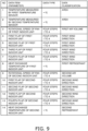
- Step S100 The data collecting operation in Step S100 will be described with reference to a flowchart of FIG. 6A and an operation point table of FIG. 7 .
- an operation point 1 is specified (S101). Operation conditions of each operation point are set in advance for each operation point. An example of the operation conditions for each operation point are shown in the operation point table of FIG. 7. FIG. 7 shows some of the operation conditions for each operation point. In FIG. 7 , a rotational speed of the fan and angles of the first to fourth flaps in each of the first user-side device 30a and the second user-side device 30b are shown as the operation conditions. Details thereof will be described in a description of the learning data set.
- the control unit 40 reads the operation conditions for the operation point 1 stored in the storage unit 41, and starts the operation of the air conditioner 10 by using the operation conditions (S102).
- Step S500 temperature saturation determination is performed in Step S500.
- the temperature saturation determination will be described in detail in (2-3) below.
- the processing proceeds to Step S103 with a result of the temperature saturation determination.
- Step S103 it is determined whether or not the temperatures measured by the first temperature sensor 15a and the second temperature sensor 15b are saturated (S103).
- Step S104 the operation condition is acquired as the learning data (S104).
- Step S104 the acquisition of the learning data (S104) is skipped and the processing proceeds to Step S105.
- Step S105 the control unit 40 determines whether or not there is a next operation point.
- the next operation point is specified (S106)
- the processing returns to S102, and Steps S102, S500, and S103 to S105 are repeated.
- the learning data is acquired or is tried to be acquired from the operation point 1 to the operation point 12 in order, such that the learning data is acquired (or is tried to be acquired) for all the operation points, and the data collecting operation is terminated.
- the temperature saturation determination flow will be described with reference to the flowchart of FIG. 6B .
- the temperature saturation determination is used not only in Step S500 of FIG. 6B in the above-described data collecting operation, but also in Step S500 of FIG. 8 in learning data collection in a normal operation.
- S500 of FIG. 6B or S500 of FIG. 8 corresponds to S501 to S507 of FIG. 6B .
- the temperature saturation determination flow is started when the setting of the operation condition of the air conditioner 10 is switched as in Step S102 of FIG. 6A or Step S301 of FIG. 8 .
- the change of the operation condition not only means that the operation condition is changed by an input from the user, but also means that the operation is started, the operation point is changed in the data collecting operation, and the operation condition is automatically changed, for example, the operation condition is changed by the scheduled operation.
- Step S501 waiting is performed for 10 minutes. Then, in Step S502, it is determined whether or not the operation condition has been changed during the waiting of 10 minutes (S501). In a case where the operation condition has been changed, the processing returns to Step S501 and waiting is performed for another 10 minutes. In a case where the operation condition has not been changed during the waiting, the processing proceeds to Step S503.
- Step S503 it is determined whether or not the temperatures measured by the first temperature sensor 15a and the second temperature sensor 15b are stable.
- the control unit 40 acquires data regarding the temperatures measured by the first temperature sensor 15a and the second temperature sensor 15b every minute.
- a state in which the temperatures measured by the temperature sensors are stable means that the change of the temperatures measured by all the temperature sensors is less than 1°C for five minutes.
- Step S503 the control unit 40 determines whether or not the temperatures measured by all the temperature sensors are stable. When the temperatures measured by all the temperature sensors are stable, it is determined that the temperatures are saturated (S504).
- Step S505 it is determined whether or not 30 minutes have elapsed from the change of the operation condition.
- Step S505 In a case where it is determined in Step S505 that 30 minutes have not elapsed from the change of the operation condition, the processing proceeds to Step S507, waiting is performed for one minute, and then the processing returns to Step S502.
- Step S505 In a case where it is determined in Step S505 that 30 minutes have elapsed from the change of the operation condition, the processing proceeds to Step S506, and it is determined that the temperatures are not saturated.
- the saturation determination for example, a method in which it is determined that the temperatures are saturated when a temperature change rate becomes less than a certain value may be used in addition to the above-described method.
- FIG. 9 is a list of the learning data set created by the machine learning (S200) of the present embodiment.
- data of the learning data set of the present embodiment is data acquired when it is determined that the values of the temperature sensors are saturated.
- the learning data set of the present embodiment includes wind direction data, refrigerant data, air volume data, and area data. Note that, in the list of FIG. 9 , each data item (parameter) is shown in a data classification column at the right end and indicates which of the wind direction data, the refrigerant data, the air volume data, and the area data is related.
- the wind direction data is data regarding a blowing-out direction of the air blown-out from the air conditioner 10.
- the wind direction data corresponds to No. 4 to No. 7, and No. 10 to No. 13.
- the wind direction data corresponds to an inclination angle of the flap.
- the inclination angles of 2 and 3 are between the inclination angles of 1 and 4.
- the refrigerant data is data regarding the temperature of the refrigerant flowing in the air conditioner or the temperature of the air blown-out from the air conditioner 10.
- the data regarding the temperature of the refrigerant flowing in the air conditioner is data regarding the temperature of the heat transfer tube of the indoor heat exchanger, the temperature of the refrigerant pipe connected to the indoor heat exchanger, and the pressure of the refrigerant flowing in the refrigerant pipe.
- the data regarding the temperature of the air blown-out from the air conditioner 10 may be a blowing-out temperature measured by arranging blowing-out temperature sensors at the blowing-out ports 34-1 to 34-4 of the air conditioner 10.
- the refrigerant data is an evaporation temperature during the cooling operation as the data regarding the temperature of the refrigerant flowing in the air conditioner.
- the refrigerant data is a temperature of the indoor heat exchanger (evaporator) measured by the indoor heat exchanger temperature sensor 13.
- No. 8 and No. 14 correspond to the refrigerant data.
- the air volume data is data regarding an air volume of the conditioned air blown-out from the air conditioner 10.
- No. 3 and No. 9 correspond to the air volume data.
- the air volume data is the rotational speed of the indoor fan 32.
- the rotational speed is changed in four steps, and the rotational speed is gradually increased from 1 to 4.
- the area data is data regarding air temperatures of the first area S1 and the second area S2.
- the area data is the measurement data of the first temperature sensor 15a and the second temperature sensor 15b.
- Step S200 The machine learning (creation of a temperature prediction model) in Step S200 will be described.
- Step S100 When the data collecting operation in Step S100 is completed, an operation point table X and acquired temperature data Y are created.
- each row corresponds to the same operation point.
- a2, b2, c2, d2, and the like correspond to the operation point 2.
- Column a (a1, a2, a3, and the like) is the temperature measured by the first temperature sensor
- Column b (b1, b2, b3, and the like) is the temperature measured by the second temperature sensor.
- Column c (c1, c2, c3, and the like) corresponds to the rotational speed of the indoor fan of the first user-side device 30a
- Column d (d1, d2, d3, and the like) corresponds to the angle of the first flap of the first user-side device 30a.
- a coefficient A is calculated by the following formula using an objective variable Y and an explanatory variable X.
- A X T ⁇ X ⁇ 1 ⁇ X T ⁇ Y
- T represents a transposed matrix and -1 represents an inverse matrix.
- a value of X is calculated from Formula (2) above, and a control corresponding to each value of X is performed (X is a matrix of the angle of each flap, the evaporation temperature, the rotational speed of the fan, and the like).
- Step S300 the control unit 40 further collects operation data while performing the normal operation.
- a learning data collection flow in the normal operation will be described with reference to the flowchart of FIG. 8 .
- a trigger in the normal operation is, for example, input of the first temperature, which is the target temperature for the first area (S1) in the room, and the second temperature, which is the target temperature for the second area (S2) in the room, to the input unit 61 of the remote controller 60 by the user (S301).
- the setting unit 70 sets the first temperature and the second temperature.
- control unit 40 performs the temperature saturation determination in Step S500.
- the details of the temperature saturation determination are as described in Steps S501 to S507 of FIG. 6B .
- Step S302 determine whether or not the temperatures measured by all the temperature sensors are saturated.
- Step S302 In a case where it is determined in Step S302 that the temperatures measured by all the temperature sensors are saturated, the learning data is acquired in Step S303, and the data collection in the normal operation is terminated.
- Step S302 In a case where it is determined in Step S302 that the temperatures measured by all the temperature sensors are not saturated, the learning data is not acquired, and the data collection in the normal operation is terminated.
- the air conditioning control system 1 further collects data while controlling the air conditioner 10 according to the user's setting by using the created learning data set (S300).
- the learning data is collected by additionally performing learning (S400) using the data set.
- the user separately sets, in the setting unit 70, the first temperature, which is the target temperature for the first area S1 in the room, and the second temperature, which is the target temperature for the second area S2 in the room. Then, the control unit 40 controls the air conditioner 10 so that the temperature of the first area S1 approaches the first temperature and the temperature of the second area S2 approaches the second temperature.
- the convenience of the user can be further enhanced.
- the temperature of the area where the person is present may differ from the target temperature for the room due to the temperature unevenness in the room.
- the user cannot spend time comfortably in the room.
- the target temperature can be set for each area, even when temperature unevenness occurs across the respective areas of the room, the temperature of the area where the person is present can be an optimum temperature. Therefore, the user can spend time comfortably in the room.
- the air conditioner can be operated for a required location with a required capacity, which saves energy.
- the first user-side device 30a and the second user-side device 30b control the air temperatures of the first area S1 and the second area S2 in a cooperative manner.
- the first temperature sensor 15a is arranged in the first area S1 and the second temperature sensor 15b is arranged in the second area S2.
- each area is registered in the storage unit 62 of the remote controller 60.
- a registration location may be another location.
- each temperature sensor is arranged in each area and fixed in each area.
- each area is registered in the air conditioning control system, the user can confirm a position of each area by using the map of the storage unit 62, and the temperature can be easily set.
- a control method of the air conditioner 10 of the present embodiment uses the learning data set including the wind direction data, the refrigerant data, the air volume data, and the area data.
- the wind direction data is data regarding a blowing-out direction of air blown-out from the air conditioner.
- the refrigerant data is data regarding a temperature of a refrigerant flowing in the air conditioner or a temperature of the air blown-out from the air conditioner.
- the air volume data is data regarding the air volume of the conditioned air blown-out from the air conditioner.
- the area data is data regarding the temperature of the air in the first area S1.
- the temperature of the air in each area can be controlled quickly and efficiently.
- Modified Example 1A is the same as that of the first embodiment except that a learning data set is different from that of the first embodiment.
- the learning data set of Modified Example 1A includes, in addition to the learning data set of the first embodiment, intake temperature data of the first user-side device of the air conditioner 10, intake temperature data of the second user-side device, outside air temperature data, thermal load data regarding a thermal load in the room, and power consumption data.
- the learning data set of Modified Example 1A includes the intake temperature data regarding the intake air temperature of the user-side device.
- the intake air temperature of the user-side device is measured by the intake temperature sensors 14a and 14b arranged near the intake port 38 of the user-side device 30. Since the learning data set of Modified Example 1A includes the intake temperature data in addition to the wind direction data, the refrigerant data, the air volume data, and the area data, the temperature of the air in the first area S1 can be controlled more accurately.
- the learning data set of Modified Example 1A includes the outside air temperature data regarding the temperature of the outside air.
- the temperature of the outside air is measured by the outside temperature sensor 12 arranged in the heat source-side device 20. Since the learning data set of Modified Example 1A includes the outside air temperature data in addition to the wind direction data, the refrigerant data, the air volume data, and the area data, the temperature of the air in the first area can be controlled more accurately.
- the learning data set of Modified Example 1A includes the thermal load data.
- the thermal load data is data regarding, for example, heat generated by a device such as a server arranged indoor in a data center. Since the learning data set of Modified Example 1A includes the thermal load data in addition to the wind direction data, the refrigerant data, the air volume data, and the area data, the air temperatures of the first area and the second area can be controlled more accurately.
- the learning data set of Modified Example 1A includes the power consumption data regarding power consumption of the air conditioner 10. Since the learning data set of Modified Example 1A includes the power consumption data in addition to the wind direction data, the refrigerant data, the air volume data, and the area data, the air temperatures of the first area and the second area can be controlled more accurately while suppressing the power consumption.
- the refrigerant data, the air volume data, and the area data for example, any one or all of the intake temperature data, the outside air temperature data, the thermal load data, and the power consumption data may be included. Further, in addition to the wind direction data, the refrigerant data, the air volume data, and the area data, for example, any two or any three of the intake temperature data, the outside air temperature data, the thermal load data, and the power consumption data may be included.
- the learning data set used in the first embodiment is acquired in a state where the temperature measured by the sensor is saturated. Data before saturation may be included as a learning data set.
- the air conditioner 10 of Modified Example 1C includes an infrared temperature sensor (infrared camera) mounted on the user-side device 30a.
- the other configurations are similar to those in the first embodiment.
- the infrared temperature sensor can measure a temperature of a person, a wall, a floor, an obstacle, or the like in a room where the sensor can directly detect infrared rays.
- the first user-side device 30a and the second user-side device 30b form a common refrigerant circuit.
- the first user-side device 30a and the second user-side device 30b of Modified Example 1D belong to independent refrigerant circuits, respectively.
- the first user-side device 30a and the second user-side device 30b of Modified Example 1D are connected to different heat source-side devices 20, respectively.
- the other configurations are similar to those in the first embodiment.
- the learning unit 50 is arranged on the control unit 40 and the server arranged via the network.
- a place where the learning unit 50 is arranged is not limited thereto.
- the learning unit of Modified Example 1E is arranged in the same computer as the control unit 40.
- the control unit 40 is arranged together with the heat source-side device 20 of the air conditioner 10 or adjacent to the heat source-side device.
- the operation data, the learning data set, and the operation point table are stored in the storage unit 41 in the heat source-side device 20.
- the location where the driving data, the learning data set, and the operation point table are stored may be another location.
- the operation data, the learning data set, and the operation point table are stored in the storage unit 51 directly connected to the learning unit 50.
- the number of user-side devices 30 of the air conditioner 10 is two.
- the number of user-side devices is not limited to two, and may be one or three or more.
- the number of user-side devices is one.
- the other configurations of the air conditioner 10 are similar to those in the first embodiment.
- a learning data set of Modified Example 1G only includes No. 1 to No. 8, and does not include No. 9 to No. 14 in FIG. 9 . Since the number of data is small, a learning time is shortened.
- a configuration of an air conditioning control system of Modified Example 1H is the same as the configuration of the air conditioning control system of the first embodiment. Further, a control method of an air conditioner of Modified Example 1H is the same as the control method of the air conditioner of the first embodiment shown in FIG. 5 . Further, a learning data set of Modified Example 1H is also the same as that described in the first embodiment. In the first embodiment, machine learning using multiple regression using the models of Formulas (1) and (2) is performed. A machine learning method is not limited thereto.
- the machine learning may be various types of machine learning such as supervised learning, unsupervised learning, semi-supervised learning, reinforcement learning, transduction, and multi-task learning.
- machine learning such as logistic regression, autoregressive integrated moving average (ARIMA), vector autoregression (VAR), support vector machine, decision tree, random forest, boosting, neural network, deep learning, K-means method, ward method, principal component analysis, and the like.
- logistic regression autoregressive integrated moving average (ARIMA), vector autoregression (VAR), support vector machine, decision tree, random forest, boosting, neural network, deep learning, K-means method, ward method, principal component analysis, and the like.
- ARIMA autoregressive integrated moving average
- VAR vector autoregression
- support vector machine decision tree
- random forest random forest
- boosting neural network
- deep learning deep learning
- K-means method K-means method
- ward method principal component analysis
- the air conditioning control system 1 controls the temperatures of the first area S1 and the second area S2 in the room. There may be three or more areas. In Modified Example 1I, there are six areas. The first to sixth temperature sensors are arranged in the first to sixth areas, respectively. The other configurations of the air conditioning control system 1 are the same as those of the first embodiment.
- the normal operation may be performed without performing the data collecting operation to collect the learning data, and the machine learning may be performed after the learning data is accumulated.
- a configuration of an air conditioning control system 1 of a second embodiment is the same as that of the air conditioning control system 1 of the first embodiment.
- a control method of an air conditioner 10 of the second embodiment is different from that of the first embodiment.
- the air conditioner 10 is controlled by performing machine learning.
- machine learning is not performed unlike the first embodiment.
- FIG. 11 is a flowchart showing of a control of the air conditioner 10 of the second embodiment.
- Step S601 the user sets a temperature for each area in a setting unit 70.
- a specific temperature setting method is the same as that of the first embodiment.
- Step S602 a control unit 40 controls a user-side device 30a and a user-side device 30b so that a temperature of air in each area approaches the set temperature based on the set temperature of the user.
- the user is allowed to move a first temperature sensor 15a and a second temperature sensor 15b in a room.
- a control unit 40 it is necessary for a control unit 40 to recognize positions of the first temperature sensor 15a and the second temperature sensor 15b moved by the user. This work may be done manually by the user or may be controlled automatically by a system 1.
- the other configurations of the air conditioning control system 1 of the present embodiment are the same as those of the first embodiment.
- the control shown in the flowchart of FIG. 5 is performed every time the positions of the first temperature sensor 15a and the second temperature sensor 15b are changed.
- the control shown in the flowchart of FIG. 5 is performed every time the positions of the first temperature sensor 15a and the second temperature sensor 15b are changed.
- the third embodiment does not have the above-described problem in a case where machine learning is not particularly performed as in the second embodiment. However, even in this case, it is necessary for the control unit 40 and a setting unit 70 to recognize the positions of the first temperature sensor 15a and the second temperature sensor 15b moved by the user.
- Patent Literature 1 JP 2012-225550 A
Landscapes
- Engineering & Computer Science (AREA)
- Signal Processing (AREA)
- Physics & Mathematics (AREA)
- Chemical & Material Sciences (AREA)
- Combustion & Propulsion (AREA)
- Mechanical Engineering (AREA)
- General Engineering & Computer Science (AREA)
- Fuzzy Systems (AREA)
- Mathematical Physics (AREA)
- General Physics & Mathematics (AREA)
- Automation & Control Theory (AREA)
- Air Conditioning Control Device (AREA)
Claims (5)
- Système de commande de climatisation (1), comprenant :un climatiseur (10) prévu pour assurer la climatisation d'une pièce ;une unité de réglage (70) prévue pour régler une première température qui est une température de consigne pour une première zone (S1) dans la pièce, et pour régler une deuxième température qui est une température de consigne pour une deuxième zone (S2) dans la pièce ; etune unité de commande (40) prévue pour commander le climatiseur,caractérisé parune unité d'apprentissage (50) prévue pour apprendre à commander le climatiseur au moyen d'un ensemble de données d'apprentissage, de sorte qu'une température de la première zone se rapproche de la première température et qu'une température de la deuxième zone se rapproche de la deuxième température,l'ensemble de données d'apprentissage comprenant des données directionnelles de courant d'air relatives à une direction de soufflage de l'air soufflé par le climatiseur,des données de réfrigérant relatives à la température d'un réfrigérant circulant dans le climatiseur ou à la température de l'air soufflé par le climatiseur,des données de volume d'air relatives au volume d'air soufflé par le climatiseur, etdes données de zone relatives à la température de l'air de la première zone et de la deuxième zone.
- Système de commande de climatisation selon la revendication 1, oùle climatiseur (10) comprend une pluralité de dispositifs côté utilisateur (30a et 30b) dans la pièce, etl'unité de commande est prévue pour commander la pluralité de dispositifs côté utilisateur de manière coopérative afin de commander la température de la première zone de manière à approcher la première température, et afin de commander la température de la deuxième zone de manière à approcher la deuxième température.
- Système de commande de climatisation selon la revendication 1 ou la revendication 2, où
l'unité de commande est prévue pour commander le climatiseur dans un état où un emplacement où est prévu un premier capteur de température (15a) dans la pièce est défini comme première zone, et un emplacement où est prévu un deuxième capteur de température (15b) dans la pièce est défini comme deuxième zone. - Système de commande de climatisation selon l'une des revendications 1 à 3, comprenant en outreune télécommande (60) disposée de manière à pouvoir communiquer avec le climatiseur (10) et comprenant l'unité de réglage (70),ladite unité de réglage étant prévue pour régler les valeurs entrées par un utilisateur en tant que première température et deuxième température.
- Système de commande de climatisation selon l'une des revendications 1 à 4, où le climatiseur (10) comprend :un dispositif côté source de chaleur ; etun dispositif côté utilisateur installé dans une pièce.
Applications Claiming Priority (2)
| Application Number | Priority Date | Filing Date | Title |
|---|---|---|---|
| JP2019153118A JP6849028B2 (ja) | 2019-08-23 | 2019-08-23 | 空調制御システム、空気調和機、および、機械学習装置 |
| PCT/JP2020/031331 WO2021039548A1 (fr) | 2019-08-23 | 2020-08-19 | Système de commande de climatisation, machine de climatisation et dispositif d'apprentissage automatique |
Publications (3)
| Publication Number | Publication Date |
|---|---|
| EP4006439A1 EP4006439A1 (fr) | 2022-06-01 |
| EP4006439A4 EP4006439A4 (fr) | 2022-08-31 |
| EP4006439B1 true EP4006439B1 (fr) | 2023-09-20 |
Family
ID=74675687
Family Applications (1)
| Application Number | Title | Priority Date | Filing Date |
|---|---|---|---|
| EP20858050.6A Active EP4006439B1 (fr) | 2019-08-23 | 2020-08-19 | Système de commande de climatisation |
Country Status (5)
| Country | Link |
|---|---|
| US (1) | US20220170659A1 (fr) |
| EP (1) | EP4006439B1 (fr) |
| JP (1) | JP6849028B2 (fr) |
| CN (1) | CN114341564A (fr) |
| WO (1) | WO2021039548A1 (fr) |
Families Citing this family (4)
| Publication number | Priority date | Publication date | Assignee | Title |
|---|---|---|---|---|
| JP7340747B2 (ja) * | 2019-08-28 | 2023-09-08 | 株式会社富士通ゼネラル | 制御方法、制御プログラムおよび空調制御装置 |
| JP7303449B2 (ja) * | 2021-03-31 | 2023-07-05 | ダイキン工業株式会社 | 空調制御装置、及び空気調和システム |
| CN113251630A (zh) * | 2021-04-26 | 2021-08-13 | 青岛海尔空调器有限总公司 | 一种空调智能控制方法、控制装置及空调系统 |
| CN115202222B (zh) * | 2022-02-24 | 2024-10-11 | 山东浪潮科学研究院有限公司 | 一种全屋温控系统及方法 |
Family Cites Families (28)
| Publication number | Priority date | Publication date | Assignee | Title |
|---|---|---|---|---|
| JPH1194327A (ja) * | 1997-09-18 | 1999-04-09 | Matsushita Seiko Co Ltd | 空気調和機の制御装置 |
| JP2003042508A (ja) * | 2001-07-25 | 2003-02-13 | Fujita Corp | 空調制御方法および空調システム |
| JP4044096B2 (ja) * | 2005-01-26 | 2008-02-06 | マイクロテック株式会社 | リモートコントロール装置 |
| JP2006342978A (ja) * | 2005-06-07 | 2006-12-21 | Daikin Ind Ltd | 空調システム |
| JP4661640B2 (ja) * | 2006-03-09 | 2011-03-30 | 株式会社日立製作所 | 空調制御システム |
| US9020647B2 (en) * | 2009-03-27 | 2015-04-28 | Siemens Industry, Inc. | System and method for climate control set-point optimization based on individual comfort |
| JP4715947B2 (ja) * | 2009-05-01 | 2011-07-06 | ダイキン工業株式会社 | 空調システム |
| JP5504845B2 (ja) * | 2009-11-25 | 2014-05-28 | ダイキン工業株式会社 | 空調制御装置 |
| JP2011208857A (ja) * | 2010-03-29 | 2011-10-20 | Daikin Industries Ltd | 空調制御システム |
| JP2011247514A (ja) * | 2010-05-27 | 2011-12-08 | Mitsubishi Electric Corp | 設備制御装置、及び、プログラム |
| JP2012225550A (ja) | 2011-04-18 | 2012-11-15 | Mitsubishi Electric Corp | 空気調和システム |
| WO2013151908A1 (fr) * | 2012-04-01 | 2013-10-10 | Mahesh Viswanathan | Système de conditionnement d'environnement multimodal en réseau extensible |
| JP2014074509A (ja) * | 2012-10-03 | 2014-04-24 | Hitachi Appliances Inc | 空調システム |
| JP5951526B2 (ja) * | 2013-03-04 | 2016-07-13 | 株式会社東芝 | 空調制御装置及び制御プログラム |
| US9719690B2 (en) * | 2013-06-19 | 2017-08-01 | Nec Corporation | Zone based heating, ventilation and air-conditioning (HVAC) control using extensive temperature monitoring |
| JP2016156511A (ja) * | 2015-02-23 | 2016-09-01 | ジョンソンコントロールズ ヒタチ エア コンディショニング テクノロジー(ホンコン)リミテッド | 空気調和機の監視制御システム |
| JP6505514B2 (ja) * | 2015-06-10 | 2019-04-24 | パナソニック株式会社 | 空気調和機、センサシステムおよびその温冷感推定方法 |
| JP2018109494A (ja) * | 2017-01-06 | 2018-07-12 | 株式会社東芝 | 空調制御装置、空調制御方法及びコンピュータプログラム |
| JP6790249B2 (ja) * | 2017-05-01 | 2020-11-25 | 三菱電機株式会社 | 空調装置、空調システム、空調方法及びプログラム |
| US11086283B2 (en) * | 2017-05-10 | 2021-08-10 | Katerra, Inc. | Method and apparatus for real property monitoring and control system |
| JP6739636B2 (ja) * | 2017-05-26 | 2020-08-12 | 三菱電機株式会社 | 空調データ通信装置、空調データ通信方法及びプログラム |
| KR101908311B1 (ko) * | 2017-05-29 | 2018-10-17 | 엘지전자 주식회사 | 공기조화기 및 공기조화 시스템 |
| JP2019066135A (ja) * | 2017-10-04 | 2019-04-25 | ファナック株式会社 | 空調制御システム |
| WO2019087537A1 (fr) * | 2017-10-30 | 2019-05-09 | ダイキン工業株式会社 | Dispositif de commande de climatisation |
| US20190187635A1 (en) * | 2017-12-15 | 2019-06-20 | Midea Group Co., Ltd | Machine learning control of environmental systems |
| US10853727B2 (en) * | 2018-02-05 | 2020-12-01 | Toyota Jidosha Kabushiki Kaisha | Machine learning system |
| CN109631265B (zh) * | 2018-12-29 | 2020-09-29 | 同济大学 | 大型公共空间舒适度智能调节系统 |
| US11649980B2 (en) * | 2019-03-20 | 2023-05-16 | Lg Electronics Inc. | Air conditioner communicating with moving agent to sense indoor space |
-
2019
- 2019-08-23 JP JP2019153118A patent/JP6849028B2/ja active Active
-
2020
- 2020-08-19 CN CN202080059670.4A patent/CN114341564A/zh active Pending
- 2020-08-19 EP EP20858050.6A patent/EP4006439B1/fr active Active
- 2020-08-19 WO PCT/JP2020/031331 patent/WO2021039548A1/fr unknown
-
2022
- 2022-02-14 US US17/671,500 patent/US20220170659A1/en active Pending
Also Published As
| Publication number | Publication date |
|---|---|
| EP4006439A1 (fr) | 2022-06-01 |
| US20220170659A1 (en) | 2022-06-02 |
| WO2021039548A1 (fr) | 2021-03-04 |
| JP6849028B2 (ja) | 2021-03-24 |
| JP2021032479A (ja) | 2021-03-01 |
| EP4006439A4 (fr) | 2022-08-31 |
| CN114341564A (zh) | 2022-04-12 |
Similar Documents
| Publication | Publication Date | Title |
|---|---|---|
| EP4006439B1 (fr) | Système de commande de climatisation | |
| JP4952722B2 (ja) | 空調吹出パネル、同空調吹出パネルを備えた空調制御システム及び空調制御方法 | |
| EP3141831B1 (fr) | Système de climatisation et de ventilation | |
| WO2019034123A1 (fr) | Procédé de commande de climatiseur intelligent et climatiseur intelligent | |
| CN114466997A (zh) | 用于个性化热舒适度控制的系统和方法 | |
| JP2009257617A (ja) | 空調システム及びその制御方法 | |
| JP2010156494A (ja) | 負荷処理バランス設定装置 | |
| JP5404556B2 (ja) | 空気調和機の制御装置および冷凍装置の制御装置 | |
| JPWO2021019761A1 (ja) | 空気調和システムおよびシステム制御装置 | |
| WO2016001975A1 (fr) | Système de climatisation | |
| JP2021032478A (ja) | 学習用データセット、および、それを用いた機械学習方法 | |
| JP6972340B2 (ja) | 空気調和システム | |
| JP2021018054A (ja) | ゾーングルーピング制御の実現可能性推定を伴う可変冷媒流量システム | |
| KR102609095B1 (ko) | 공기조화기 및 그 제어방법 | |
| US11940166B2 (en) | Air conditioning system for transferring air in an air-conditioned room | |
| US20210048215A1 (en) | System and Method for Optimizing Energy Use of a Structure Using a Clustering-Based Rule-Mining Approach | |
| KR20120135617A (ko) | 공기조화시스템 | |
| JP2009299965A (ja) | 空調システム | |
| KR102123950B1 (ko) | 에너지 절감현황 표시 시스템, 및 방법 | |
| CN117242306A (zh) | 空调控制装置 | |
| WO2023181324A1 (fr) | Dispositif de commande de climatisation, système de climatisation, procédé de commande de climatisation, et programme | |
| JP7329332B2 (ja) | 空気調和システム及び空気調和システムの制御方法 | |
| JPH0942739A (ja) | ホテルの空調制御システム | |
| CN117677965B (zh) | 区域通知系统 | |
| JP7361625B2 (ja) | 空調システム |
Legal Events
| Date | Code | Title | Description |
|---|---|---|---|
| STAA | Information on the status of an ep patent application or granted ep patent |
Free format text: STATUS: THE INTERNATIONAL PUBLICATION HAS BEEN MADE |
|
| PUAI | Public reference made under article 153(3) epc to a published international application that has entered the european phase |
Free format text: ORIGINAL CODE: 0009012 |
|
| STAA | Information on the status of an ep patent application or granted ep patent |
Free format text: STATUS: REQUEST FOR EXAMINATION WAS MADE |
|
| 17P | Request for examination filed |
Effective date: 20220216 |
|
| AK | Designated contracting states |
Kind code of ref document: A1 Designated state(s): AL AT BE BG CH CY CZ DE DK EE ES FI FR GB GR HR HU IE IS IT LI LT LU LV MC MK MT NL NO PL PT RO RS SE SI SK SM TR |
|
| A4 | Supplementary search report drawn up and despatched |
Effective date: 20220803 |
|
| RIC1 | Information provided on ipc code assigned before grant |
Ipc: G05B 19/00 20060101ALI20220728BHEP Ipc: F24F 11/72 20180101ALI20220728BHEP Ipc: F24F 11/63 20180101ALI20220728BHEP Ipc: F24F 11/62 20180101ALI20220728BHEP Ipc: F24F 110/30 20180101ALI20220728BHEP Ipc: F24F 110/10 20180101ALI20220728BHEP Ipc: F24F 11/80 20180101ALI20220728BHEP Ipc: F24F 11/79 20180101ALI20220728BHEP Ipc: F24F 11/74 20180101ALI20220728BHEP Ipc: F24F 11/64 20180101ALI20220728BHEP Ipc: F24F 11/46 20180101AFI20220728BHEP |
|
| DAV | Request for validation of the european patent (deleted) | ||
| DAX | Request for extension of the european patent (deleted) | ||
| RAP3 | Party data changed (applicant data changed or rights of an application transferred) |
Owner name: DAIKIN INDUSTRIES, LTD. |
|
| GRAP | Despatch of communication of intention to grant a patent |
Free format text: ORIGINAL CODE: EPIDOSNIGR1 |
|
| STAA | Information on the status of an ep patent application or granted ep patent |
Free format text: STATUS: GRANT OF PATENT IS INTENDED |
|
| RIC1 | Information provided on ipc code assigned before grant |
Ipc: G05B 19/042 20060101ALI20230511BHEP Ipc: G05B 19/00 20060101ALI20230511BHEP Ipc: F24F 11/72 20180101ALI20230511BHEP Ipc: F24F 11/63 20180101ALI20230511BHEP Ipc: F24F 11/62 20180101ALI20230511BHEP Ipc: F24F 110/30 20180101ALI20230511BHEP Ipc: F24F 110/10 20180101ALI20230511BHEP Ipc: F24F 11/80 20180101ALI20230511BHEP Ipc: F24F 11/79 20180101ALI20230511BHEP Ipc: F24F 11/74 20180101ALI20230511BHEP Ipc: F24F 11/64 20180101ALI20230511BHEP Ipc: F24F 11/46 20180101AFI20230511BHEP |
|
| INTG | Intention to grant announced |
Effective date: 20230609 |
|
| P01 | Opt-out of the competence of the unified patent court (upc) registered |
Effective date: 20230525 |
|
| GRAS | Grant fee paid |
Free format text: ORIGINAL CODE: EPIDOSNIGR3 |
|
| GRAA | (expected) grant |
Free format text: ORIGINAL CODE: 0009210 |
|
| STAA | Information on the status of an ep patent application or granted ep patent |
Free format text: STATUS: THE PATENT HAS BEEN GRANTED |
|
| AK | Designated contracting states |
Kind code of ref document: B1 Designated state(s): AL AT BE BG CH CY CZ DE DK EE ES FI FR GB GR HR HU IE IS IT LI LT LU LV MC MK MT NL NO PL PT RO RS SE SI SK SM TR |
|
| REG | Reference to a national code |
Ref country code: GB Ref legal event code: FG4D |
|
| REG | Reference to a national code |
Ref country code: CH Ref legal event code: EP |
|
| REG | Reference to a national code |
Ref country code: IE Ref legal event code: FG4D |
|
| REG | Reference to a national code |
Ref country code: DE Ref legal event code: R096 Ref document number: 602020018075 Country of ref document: DE |
|
| REG | Reference to a national code |
Ref country code: LT Ref legal event code: MG9D |
|
| PG25 | Lapsed in a contracting state [announced via postgrant information from national office to epo] |
Ref country code: GR Free format text: LAPSE BECAUSE OF FAILURE TO SUBMIT A TRANSLATION OF THE DESCRIPTION OR TO PAY THE FEE WITHIN THE PRESCRIBED TIME-LIMIT Effective date: 20231221 |
|
| REG | Reference to a national code |
Ref country code: NL Ref legal event code: MP Effective date: 20230920 |
|
| PG25 | Lapsed in a contracting state [announced via postgrant information from national office to epo] |
Ref country code: SE Free format text: LAPSE BECAUSE OF FAILURE TO SUBMIT A TRANSLATION OF THE DESCRIPTION OR TO PAY THE FEE WITHIN THE PRESCRIBED TIME-LIMIT Effective date: 20230920 Ref country code: RS Free format text: LAPSE BECAUSE OF FAILURE TO SUBMIT A TRANSLATION OF THE DESCRIPTION OR TO PAY THE FEE WITHIN THE PRESCRIBED TIME-LIMIT Effective date: 20230920 Ref country code: NO Free format text: LAPSE BECAUSE OF FAILURE TO SUBMIT A TRANSLATION OF THE DESCRIPTION OR TO PAY THE FEE WITHIN THE PRESCRIBED TIME-LIMIT Effective date: 20231220 Ref country code: LV Free format text: LAPSE BECAUSE OF FAILURE TO SUBMIT A TRANSLATION OF THE DESCRIPTION OR TO PAY THE FEE WITHIN THE PRESCRIBED TIME-LIMIT Effective date: 20230920 Ref country code: LT Free format text: LAPSE BECAUSE OF FAILURE TO SUBMIT A TRANSLATION OF THE DESCRIPTION OR TO PAY THE FEE WITHIN THE PRESCRIBED TIME-LIMIT Effective date: 20230920 Ref country code: HR Free format text: LAPSE BECAUSE OF FAILURE TO SUBMIT A TRANSLATION OF THE DESCRIPTION OR TO PAY THE FEE WITHIN THE PRESCRIBED TIME-LIMIT Effective date: 20230920 Ref country code: GR Free format text: LAPSE BECAUSE OF FAILURE TO SUBMIT A TRANSLATION OF THE DESCRIPTION OR TO PAY THE FEE WITHIN THE PRESCRIBED TIME-LIMIT Effective date: 20231221 Ref country code: FI Free format text: LAPSE BECAUSE OF FAILURE TO SUBMIT A TRANSLATION OF THE DESCRIPTION OR TO PAY THE FEE WITHIN THE PRESCRIBED TIME-LIMIT Effective date: 20230920 |
|
| REG | Reference to a national code |
Ref country code: AT Ref legal event code: MK05 Ref document number: 1613651 Country of ref document: AT Kind code of ref document: T Effective date: 20230920 |
|
| PG25 | Lapsed in a contracting state [announced via postgrant information from national office to epo] |
Ref country code: NL Free format text: LAPSE BECAUSE OF FAILURE TO SUBMIT A TRANSLATION OF THE DESCRIPTION OR TO PAY THE FEE WITHIN THE PRESCRIBED TIME-LIMIT Effective date: 20230920 |
|
| PG25 | Lapsed in a contracting state [announced via postgrant information from national office to epo] |
Ref country code: IS Free format text: LAPSE BECAUSE OF FAILURE TO SUBMIT A TRANSLATION OF THE DESCRIPTION OR TO PAY THE FEE WITHIN THE PRESCRIBED TIME-LIMIT Effective date: 20240120 |
|
| PG25 | Lapsed in a contracting state [announced via postgrant information from national office to epo] |
Ref country code: AT Free format text: LAPSE BECAUSE OF FAILURE TO SUBMIT A TRANSLATION OF THE DESCRIPTION OR TO PAY THE FEE WITHIN THE PRESCRIBED TIME-LIMIT Effective date: 20230920 |
|
| PG25 | Lapsed in a contracting state [announced via postgrant information from national office to epo] |
Ref country code: ES Free format text: LAPSE BECAUSE OF FAILURE TO SUBMIT A TRANSLATION OF THE DESCRIPTION OR TO PAY THE FEE WITHIN THE PRESCRIBED TIME-LIMIT Effective date: 20230920 |
|
| PG25 | Lapsed in a contracting state [announced via postgrant information from national office to epo] |
Ref country code: SM Free format text: LAPSE BECAUSE OF FAILURE TO SUBMIT A TRANSLATION OF THE DESCRIPTION OR TO PAY THE FEE WITHIN THE PRESCRIBED TIME-LIMIT Effective date: 20230920 Ref country code: RO Free format text: LAPSE BECAUSE OF FAILURE TO SUBMIT A TRANSLATION OF THE DESCRIPTION OR TO PAY THE FEE WITHIN THE PRESCRIBED TIME-LIMIT Effective date: 20230920 Ref country code: IS Free format text: LAPSE BECAUSE OF FAILURE TO SUBMIT A TRANSLATION OF THE DESCRIPTION OR TO PAY THE FEE WITHIN THE PRESCRIBED TIME-LIMIT Effective date: 20240120 Ref country code: ES Free format text: LAPSE BECAUSE OF FAILURE TO SUBMIT A TRANSLATION OF THE DESCRIPTION OR TO PAY THE FEE WITHIN THE PRESCRIBED TIME-LIMIT Effective date: 20230920 Ref country code: EE Free format text: LAPSE BECAUSE OF FAILURE TO SUBMIT A TRANSLATION OF THE DESCRIPTION OR TO PAY THE FEE WITHIN THE PRESCRIBED TIME-LIMIT Effective date: 20230920 Ref country code: CZ Free format text: LAPSE BECAUSE OF FAILURE TO SUBMIT A TRANSLATION OF THE DESCRIPTION OR TO PAY THE FEE WITHIN THE PRESCRIBED TIME-LIMIT Effective date: 20230920 Ref country code: AT Free format text: LAPSE BECAUSE OF FAILURE TO SUBMIT A TRANSLATION OF THE DESCRIPTION OR TO PAY THE FEE WITHIN THE PRESCRIBED TIME-LIMIT Effective date: 20230920 Ref country code: SK Free format text: LAPSE BECAUSE OF FAILURE TO SUBMIT A TRANSLATION OF THE DESCRIPTION OR TO PAY THE FEE WITHIN THE PRESCRIBED TIME-LIMIT Effective date: 20230920 Ref country code: PT Free format text: LAPSE BECAUSE OF FAILURE TO SUBMIT A TRANSLATION OF THE DESCRIPTION OR TO PAY THE FEE WITHIN THE PRESCRIBED TIME-LIMIT Effective date: 20240122 |
|
| PG25 | Lapsed in a contracting state [announced via postgrant information from national office to epo] |
Ref country code: PL Free format text: LAPSE BECAUSE OF FAILURE TO SUBMIT A TRANSLATION OF THE DESCRIPTION OR TO PAY THE FEE WITHIN THE PRESCRIBED TIME-LIMIT Effective date: 20230920 |
|
| REG | Reference to a national code |
Ref country code: DE Ref legal event code: R097 Ref document number: 602020018075 Country of ref document: DE |
|
| PG25 | Lapsed in a contracting state [announced via postgrant information from national office to epo] |
Ref country code: DK Free format text: LAPSE BECAUSE OF FAILURE TO SUBMIT A TRANSLATION OF THE DESCRIPTION OR TO PAY THE FEE WITHIN THE PRESCRIBED TIME-LIMIT Effective date: 20230920 |
|
| PLBE | No opposition filed within time limit |
Free format text: ORIGINAL CODE: 0009261 |
|
| STAA | Information on the status of an ep patent application or granted ep patent |
Free format text: STATUS: NO OPPOSITION FILED WITHIN TIME LIMIT |
|
| PG25 | Lapsed in a contracting state [announced via postgrant information from national office to epo] |
Ref country code: DK Free format text: LAPSE BECAUSE OF FAILURE TO SUBMIT A TRANSLATION OF THE DESCRIPTION OR TO PAY THE FEE WITHIN THE PRESCRIBED TIME-LIMIT Effective date: 20230920 |
|
| 26N | No opposition filed |
Effective date: 20240621 |
|
| PGFP | Annual fee paid to national office [announced via postgrant information from national office to epo] |
Ref country code: DE Payment date: 20240821 Year of fee payment: 5 |
|
| PGFP | Annual fee paid to national office [announced via postgrant information from national office to epo] |
Ref country code: GB Payment date: 20240826 Year of fee payment: 5 |
|
| PGFP | Annual fee paid to national office [announced via postgrant information from national office to epo] |
Ref country code: FR Payment date: 20240830 Year of fee payment: 5 |
|
| PG25 | Lapsed in a contracting state [announced via postgrant information from national office to epo] |
Ref country code: SI Free format text: LAPSE BECAUSE OF FAILURE TO SUBMIT A TRANSLATION OF THE DESCRIPTION OR TO PAY THE FEE WITHIN THE PRESCRIBED TIME-LIMIT Effective date: 20230920 |
|
| PG25 | Lapsed in a contracting state [announced via postgrant information from national office to epo] |
Ref country code: SI Free format text: LAPSE BECAUSE OF FAILURE TO SUBMIT A TRANSLATION OF THE DESCRIPTION OR TO PAY THE FEE WITHIN THE PRESCRIBED TIME-LIMIT Effective date: 20230920 |
|
| PGFP | Annual fee paid to national office [announced via postgrant information from national office to epo] |
Ref country code: IT Payment date: 20240827 Year of fee payment: 5 |