EP4000468B1 - Cold storage - Google Patents
Cold storage Download PDFInfo
- Publication number
- EP4000468B1 EP4000468B1 EP20855864.3A EP20855864A EP4000468B1 EP 4000468 B1 EP4000468 B1 EP 4000468B1 EP 20855864 A EP20855864 A EP 20855864A EP 4000468 B1 EP4000468 B1 EP 4000468B1
- Authority
- EP
- European Patent Office
- Prior art keywords
- sliding door
- recorder
- refrigeration compartment
- housing
- refrigerator
- Prior art date
- Legal status (The legal status is an assumption and is not a legal conclusion. Google has not performed a legal analysis and makes no representation as to the accuracy of the status listed.)
- Active
Links
Images


Classifications
-
- F—MECHANICAL ENGINEERING; LIGHTING; HEATING; WEAPONS; BLASTING
- F25—REFRIGERATION OR COOLING; COMBINED HEATING AND REFRIGERATION SYSTEMS; HEAT PUMP SYSTEMS; MANUFACTURE OR STORAGE OF ICE; LIQUEFACTION SOLIDIFICATION OF GASES
- F25D—REFRIGERATORS; COLD ROOMS; ICE-BOXES; COOLING OR FREEZING APPARATUS NOT OTHERWISE PROVIDED FOR
- F25D17/00—Arrangements for circulating cooling fluids; Arrangements for circulating gas, e.g. air, within refrigerated spaces
- F25D17/04—Arrangements for circulating cooling fluids; Arrangements for circulating gas, e.g. air, within refrigerated spaces for circulating air, e.g. by convection
- F25D17/06—Arrangements for circulating cooling fluids; Arrangements for circulating gas, e.g. air, within refrigerated spaces for circulating air, e.g. by convection by forced circulation
-
- F—MECHANICAL ENGINEERING; LIGHTING; HEATING; WEAPONS; BLASTING
- F25—REFRIGERATION OR COOLING; COMBINED HEATING AND REFRIGERATION SYSTEMS; HEAT PUMP SYSTEMS; MANUFACTURE OR STORAGE OF ICE; LIQUEFACTION SOLIDIFICATION OF GASES
- F25D—REFRIGERATORS; COLD ROOMS; ICE-BOXES; COOLING OR FREEZING APPARATUS NOT OTHERWISE PROVIDED FOR
- F25D21/00—Defrosting; Preventing frosting; Removing condensed or defrost water
- F25D21/04—Preventing the formation of frost or condensate
-
- A—HUMAN NECESSITIES
- A47—FURNITURE; DOMESTIC ARTICLES OR APPLIANCES; COFFEE MILLS; SPICE MILLS; SUCTION CLEANERS IN GENERAL
- A47F—SPECIAL FURNITURE, FITTINGS, OR ACCESSORIES FOR SHOPS, STOREHOUSES, BARS, RESTAURANTS OR THE LIKE; PAYING COUNTERS
- A47F3/00—Show cases or show cabinets
- A47F3/04—Show cases or show cabinets air-conditioned, refrigerated
- A47F3/0404—Cases or cabinets of the closed type
- A47F3/0408—Cases or cabinets of the closed type with forced air circulation
-
- A—HUMAN NECESSITIES
- A47—FURNITURE; DOMESTIC ARTICLES OR APPLIANCES; COFFEE MILLS; SPICE MILLS; SUCTION CLEANERS IN GENERAL
- A47F—SPECIAL FURNITURE, FITTINGS, OR ACCESSORIES FOR SHOPS, STOREHOUSES, BARS, RESTAURANTS OR THE LIKE; PAYING COUNTERS
- A47F3/00—Show cases or show cabinets
- A47F3/04—Show cases or show cabinets air-conditioned, refrigerated
- A47F3/0404—Cases or cabinets of the closed type
- A47F3/0426—Details
- A47F3/043—Doors, covers
-
- F—MECHANICAL ENGINEERING; LIGHTING; HEATING; WEAPONS; BLASTING
- F25—REFRIGERATION OR COOLING; COMBINED HEATING AND REFRIGERATION SYSTEMS; HEAT PUMP SYSTEMS; MANUFACTURE OR STORAGE OF ICE; LIQUEFACTION SOLIDIFICATION OF GASES
- F25D—REFRIGERATORS; COLD ROOMS; ICE-BOXES; COOLING OR FREEZING APPARATUS NOT OTHERWISE PROVIDED FOR
- F25D23/00—General constructional features
- F25D23/003—General constructional features for cooling refrigerating machinery
-
- F—MECHANICAL ENGINEERING; LIGHTING; HEATING; WEAPONS; BLASTING
- F25—REFRIGERATION OR COOLING; COMBINED HEATING AND REFRIGERATION SYSTEMS; HEAT PUMP SYSTEMS; MANUFACTURE OR STORAGE OF ICE; LIQUEFACTION SOLIDIFICATION OF GASES
- F25D—REFRIGERATORS; COLD ROOMS; ICE-BOXES; COOLING OR FREEZING APPARATUS NOT OTHERWISE PROVIDED FOR
- F25D23/00—General constructional features
- F25D23/02—Doors; Covers
- F25D23/021—Sliding doors
-
- F—MECHANICAL ENGINEERING; LIGHTING; HEATING; WEAPONS; BLASTING
- F25—REFRIGERATION OR COOLING; COMBINED HEATING AND REFRIGERATION SYSTEMS; HEAT PUMP SYSTEMS; MANUFACTURE OR STORAGE OF ICE; LIQUEFACTION SOLIDIFICATION OF GASES
- F25D—REFRIGERATORS; COLD ROOMS; ICE-BOXES; COOLING OR FREEZING APPARATUS NOT OTHERWISE PROVIDED FOR
- F25D29/00—Arrangement or mounting of control or safety devices
-
- F—MECHANICAL ENGINEERING; LIGHTING; HEATING; WEAPONS; BLASTING
- F25—REFRIGERATION OR COOLING; COMBINED HEATING AND REFRIGERATION SYSTEMS; HEAT PUMP SYSTEMS; MANUFACTURE OR STORAGE OF ICE; LIQUEFACTION SOLIDIFICATION OF GASES
- F25D—REFRIGERATORS; COLD ROOMS; ICE-BOXES; COOLING OR FREEZING APPARATUS NOT OTHERWISE PROVIDED FOR
- F25D2317/00—Details or arrangements for circulating cooling fluids; Details or arrangements for circulating gas, e.g. air, within refrigerated spaces, not provided for in other groups of this subclass
- F25D2317/06—Details or arrangements for circulating cooling fluids; Details or arrangements for circulating gas, e.g. air, within refrigerated spaces, not provided for in other groups of this subclass with forced air circulation
- F25D2317/065—Details or arrangements for circulating cooling fluids; Details or arrangements for circulating gas, e.g. air, within refrigerated spaces, not provided for in other groups of this subclass with forced air circulation characterised by the air return
- F25D2317/0651—Details or arrangements for circulating cooling fluids; Details or arrangements for circulating gas, e.g. air, within refrigerated spaces, not provided for in other groups of this subclass with forced air circulation characterised by the air return through the bottom
-
- F—MECHANICAL ENGINEERING; LIGHTING; HEATING; WEAPONS; BLASTING
- F25—REFRIGERATION OR COOLING; COMBINED HEATING AND REFRIGERATION SYSTEMS; HEAT PUMP SYSTEMS; MANUFACTURE OR STORAGE OF ICE; LIQUEFACTION SOLIDIFICATION OF GASES
- F25D—REFRIGERATORS; COLD ROOMS; ICE-BOXES; COOLING OR FREEZING APPARATUS NOT OTHERWISE PROVIDED FOR
- F25D2321/00—Details or arrangements for defrosting; Preventing frosting; Removing condensed or defrost water, not provided for in other groups of this subclass
- F25D2321/14—Collecting condense or defrost water; Removing condense or defrost water
- F25D2321/142—Collecting condense or defrost water; Removing condense or defrost water characterised by droplet guides
-
- F—MECHANICAL ENGINEERING; LIGHTING; HEATING; WEAPONS; BLASTING
- F25—REFRIGERATION OR COOLING; COMBINED HEATING AND REFRIGERATION SYSTEMS; HEAT PUMP SYSTEMS; MANUFACTURE OR STORAGE OF ICE; LIQUEFACTION SOLIDIFICATION OF GASES
- F25D—REFRIGERATORS; COLD ROOMS; ICE-BOXES; COOLING OR FREEZING APPARATUS NOT OTHERWISE PROVIDED FOR
- F25D2323/00—General constructional features not provided for in other groups of this subclass
- F25D2323/002—Details for cooling refrigerating machinery
- F25D2323/0021—Details for cooling refrigerating machinery using air guides
-
- F—MECHANICAL ENGINEERING; LIGHTING; HEATING; WEAPONS; BLASTING
- F25—REFRIGERATION OR COOLING; COMBINED HEATING AND REFRIGERATION SYSTEMS; HEAT PUMP SYSTEMS; MANUFACTURE OR STORAGE OF ICE; LIQUEFACTION SOLIDIFICATION OF GASES
- F25D—REFRIGERATORS; COLD ROOMS; ICE-BOXES; COOLING OR FREEZING APPARATUS NOT OTHERWISE PROVIDED FOR
- F25D2323/00—General constructional features not provided for in other groups of this subclass
- F25D2323/002—Details for cooling refrigerating machinery
- F25D2323/0026—Details for cooling refrigerating machinery characterised by the incoming air flow
- F25D2323/00261—Details for cooling refrigerating machinery characterised by the incoming air flow through the back bottom side
-
- F—MECHANICAL ENGINEERING; LIGHTING; HEATING; WEAPONS; BLASTING
- F25—REFRIGERATION OR COOLING; COMBINED HEATING AND REFRIGERATION SYSTEMS; HEAT PUMP SYSTEMS; MANUFACTURE OR STORAGE OF ICE; LIQUEFACTION SOLIDIFICATION OF GASES
- F25D—REFRIGERATORS; COLD ROOMS; ICE-BOXES; COOLING OR FREEZING APPARATUS NOT OTHERWISE PROVIDED FOR
- F25D2323/00—General constructional features not provided for in other groups of this subclass
- F25D2323/002—Details for cooling refrigerating machinery
- F25D2323/0027—Details for cooling refrigerating machinery characterised by the out-flowing air
- F25D2323/00274—Details for cooling refrigerating machinery characterised by the out-flowing air from the front bottom
-
- F—MECHANICAL ENGINEERING; LIGHTING; HEATING; WEAPONS; BLASTING
- F25—REFRIGERATION OR COOLING; COMBINED HEATING AND REFRIGERATION SYSTEMS; HEAT PUMP SYSTEMS; MANUFACTURE OR STORAGE OF ICE; LIQUEFACTION SOLIDIFICATION OF GASES
- F25D—REFRIGERATORS; COLD ROOMS; ICE-BOXES; COOLING OR FREEZING APPARATUS NOT OTHERWISE PROVIDED FOR
- F25D2400/00—General features of, or devices for refrigerators, cold rooms, ice-boxes, or for cooling or freezing apparatus not covered by any other subclass
- F25D2400/36—Visual displays
-
- F—MECHANICAL ENGINEERING; LIGHTING; HEATING; WEAPONS; BLASTING
- F25—REFRIGERATION OR COOLING; COMBINED HEATING AND REFRIGERATION SYSTEMS; HEAT PUMP SYSTEMS; MANUFACTURE OR STORAGE OF ICE; LIQUEFACTION SOLIDIFICATION OF GASES
- F25D—REFRIGERATORS; COLD ROOMS; ICE-BOXES; COOLING OR FREEZING APPARATUS NOT OTHERWISE PROVIDED FOR
- F25D2700/00—Means for sensing or measuring; Sensors therefor
- F25D2700/12—Sensors measuring the inside temperature
Definitions
- the present disclosure relates to a refrigerator including a sliding door.
- the inner surface of the door for opening and closing the refrigeration compartment is also cooled.
- the outer surface of the door is also cooled depending on the case. In this case, the moisture in the outside air, i.e., the air surrounding the outer surface of the door may condense, and cause condensation on the outer surface of the door.
- PTL 1 discloses a cooling storage that supplies, to the outer surface of the glass door, the relatively warm air in a machine compartment located on the lower side of the storage compartment for the purpose of preventing the condensation at the outer surface of the glass door.
- Patent Application Laid-Open No. JP 2000- 88 438 A Document JP 2001- 245 759 A relates to a low-temperature showcase comprising sliding glass doors for opening/closing a front opening of a storage room, a machine room located below the storage room and provided with a fan for a condenser, and a machine room cover located in the front of the machine room.
- a blow-out part for blowing upward is formed at the upper part of the machine room cover on the side of one glass door, and blow-out parts for blowing upward and backward are each formed at the upper part of the machine room cover on the side of the other glass door.
- Document JP 2009- 198 058 A relates to a exhaust guide cover including a tabular front plate part, side plate parts arranged on both right and left side edges of this front plate part, and a lower plate part arranged on the lower edge of the front plate part.
- the exhaust guide cover is detachably installed on a front panel of the machine room, and is constituted so that a guide passage for upwardly guiding air exhausted from an exhaust part, is defined between the front panel part extending to the front side of the exhaust part and a front face of the front panel by separating from the front face of the front panel.
- An object of the present disclosure is to provide a refrigerator in which the generation of condensation at a sliding door is suppressed.
- the present disclosure can provide a refrigerator in which the generation of condensation at a sliding door is suppressed.
- Fig. 1 is a perspective view of refrigerator 1 according to the present disclosure.
- Fig. 1 illustrates a state where outer sliding door 4 and inner sliding door 5 described later are at a fully closed position.
- Fig. 2 is a cross-sectional view taken along II-II of Fig. 1 . Note that in Fig. 2 , the illustration of condenser CD is omitted.
- Fig. 3 is a schematic plan view illustrating an arrangement of apparatuses in machine compartment MR provided in refrigerator 1 of the present disclosure.
- refrigerator 1 of the present embodiment is, for example, a medicine refrigerator for storing pharmaceutical drugs.
- the front side of refrigerator 1 is the side facing the user using it (the side on which outer sliding door 4 and inner sliding door 5 are provided), and the side opposite to the front side is the rear side of refrigerator 1.
- the left side and the right side as viewed from the front side are the left side and the right side of refrigerator 1.
- Refrigerator 1 includes housing 2, frame body 3, outer sliding door (first sliding door) 4, and inner sliding door (second sliding door) 5.
- Opening H is formed in the front surface of housing 2.
- a heat insulation material is provided between the outer peripheral surface and the inner peripheral surface of housing 2.
- the space surrounded by the inner peripheral surface of housing 2 is refrigeration compartment R, which is a space for housing an object (see Fig. 2 ).
- the internal space on the lower side of refrigeration compartment R is machine compartment MR. Refrigeration compartment R and machine compartment MR are parted, and ventilation between refrigeration compartment R and machine compartment MR is not allowed. Note that housing 2 and machine compartment MR are elaborated later.
- Frame body 3 is provided in housing 2 to surround opening H.
- outer lane 31 and inner lane 32 are formed (see Fig. 2 ).
- outer lane 31 is located on the front side than inner lane 32.
- guiding hole 3a for guiding condensation water generated at outer sliding door 4, inner sliding door 5 or frame body 3 to machine compartment MR is formed (see Fig. 3 ).
- Guiding hole 3a is provided at a center portion of the lower frame part of frame body 3 as viewed from the front. Condensation water past guiding hole 3a flows into machine compartment MR through pipe TB described later.
- outer sliding door 4 is disposed on outer lane 31, and inner sliding door 5 is disposed on inner lane 32.
- Outer sliding door 4 opens and closes refrigeration compartment R by moving in the horizontal direction on outer lane 31.
- Inner sliding door 5 opens and closes refrigeration compartment R by moving in the horizontal direction on inner lane 32.
- Inner sliding door 5 is located between refrigeration compartment R and outer sliding door 4 when refrigeration compartment R is in the fully opened state. Note that the opening direction and the closing direction of outer sliding door 4 correspond to the left direction and the right direction, respectively, and the opening direction and the closing direction of inner sliding door 5 correspond to the right direction and the left direction, respectively.
- Outer sliding door 4 and inner sliding door 5 are doors including a glass layer.
- 41 and 51 in Fig. 1 are the closing end of outer sliding door 4 and the closing end of inner sliding door 5, respectively.
- Closing end 41 and closing end 51 are end parts on the closing direction side of the sash of outer sliding door 4 and inner sliding door 5, respectively.
- Outer surface 42 and 43 in Fig. 2 are the outer surface and the inner surface of outer sliding door 4, respectively.
- Outer surface 42 is the surface on the outer side (forward side) of refrigeration compartment R
- inner surface 43 is the surface on the refrigeration compartment R side (rear side).
- 52 and 53 in Fig. 2 are the outer surface and the inner surface of inner sliding door 5.
- Outer surface 52 is the surface on the outer side (forward side) of refrigeration compartment R
- inner surface 53 is the surface on the refrigeration compartment R side (rear side).
- 44 and 54 in Fig. 1 are handles provided at outer sliding door 4 and inner sliding door 5, respectively. When opening or closing outer sliding door 4 and inner sliding door 5, the user grabs handle 44 and handle 54, respectively.
- housing 2 includes front surface panel 21, recorder attaching part 22, and eaves 23.
- Front surface panel 21 covers the front side of machine compartment MR (see Fig. 2 ). Recorder RC described later is attached to recorder attaching part 22. Recorder attaching part 22 is located on the right side of the surface of front surface panel 21 on machine compartment MR side.
- 4S in Fig. 3 is an orthogonal projection of outer sliding door 4 to the bottom surface of housing 2
- 5S is an orthogonal projection of inner sliding door 5 to the bottom surface of housing 2.
- the range indicated by the chain double-dashed line in Fig. 3 represents the range of an orthogonal projection of air blow port 2a to the bottom surface.
- recorder attaching part 22 is disposed inside housing 2 at a position closer to closing end 41 of outer sliding door 4 in the fully closed state than closing end 51 of inner sliding door 5 in the fully closed state.
- Eaves 23 is a component that covers recorder RC attached to recorder attaching part 22, from above. Eaves 23 is attached to the surface of front surface panel 21 on machine compartment MR side, and is located on the upper side of recorder attaching part 22.
- Air blow port 2a facing upward is formed in front of frame body 3.
- Air blow port 2a is a hole that blows out the airflow inside machine compartment MR toward outer sliding door 4 and inner sliding door 5.
- Fig. 1 illustrates a state where air blow port 2a as a single hole is formed from closing end 41 of outer sliding door 4 in the fully closed state to closing end 51 of inner sliding door 5 in the fully closed state. Note that a plurality of holes may be formed as air blow port 2a.
- Housing 2 houses in its inside compressor CP, condenser CD, fan F, recorder RC, and pipe TB.
- compressor CP, condenser CD, fan F, recorder RC, and pipe TB are disposed inside machine compartment MR.
- Compressor CP and condenser CD make up a refrigeration circuit for cooling the inside of refrigeration compartment R.
- Compressor CP and condenser CD emit heat during operation, and therefore the air surrounding compressor CP and condenser CD is heated.
- Compressor CP is disposed on the left side in machine compartment MR. Specifically, compressor CP is disposed at a position closer to closing end 51 of inner sliding door 5 in the fully closed state than closing end 41 of outer sliding door 4 in the fully closed state.
- Condenser CD is disposed at a center portion in the horizontal direction inside housing 2. Condenser CD, as with compressor CP, is disposed at a position closer to closing end 51 of inner sliding door 5 in the fully closed state than closing end 41 of outer sliding door 4 in the fully closed state.
- fan F takes in the air outside refrigerator 1 from the intake port (not illustrated in the drawing) formed on the rear side of housing 2, and sends the taken air toward condenser CD to cool condenser CD.
- Fan F generates not only the airflow that passes through the periphery of condenser CD, but also the airflow that passes through the periphery of compressor CP.
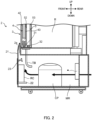
- Fig. 2 illustrates an airflow generated by fan F.
- the airflow generated by fan F is output from air blow port 2a toward outer surface 42 of outer sliding door 4 and outer surface 52 of inner sliding door 5.
- Recorder RC is an apparatus that records the temperature of refrigeration compartment R.
- recorder RC prints the measurement result on a recording sheet and outputs it to the outside of refrigerator 1.
- Recorder RC is housed in housing 2, and is attached to recorder attaching part 22. Note that recorder RC is manufactured separately from refrigerator 1, and is housed into housing 2 from the door of front surface panel 21 after refrigerator 1 is manufactured. In addition, recorder RC may be attached in place of the door of front surface panel 21, and the upper side of recorder RC is covered with eaves 23.
- eaves 23 is provided on machine compartment MR side of front surface panel 21, it may be provided, on the upper side of recorder RC, integrally with recorder RC to be replaced.
- eaves 23 has a shape that guides, toward air blow port 2a, the airflow generated by fan F.
- eaves 23 may have a shape with a first flat plate part, a second flat plate part, and a wall part. The first flat plate part extends in a direction away from front surface panel 21 from the inner surface of front surface panel 21.
- the second flat plate part extends downward in the direction away from front surface panel 21 from the end part of the first flat plate part on the side opposite to front surface panel 21, and extends from the left end to the right end of the first flat plate part.
- the wall part protrudes upward from the end part and extends from the left end to the right end of the first flat plate part.
- eaves 23 covers the portion on front surface panel 21 side of recorder RC and recorder attaching part 22 in Fig. 3 , it may cover the entire range on the upper side of recorder attaching part 22 and recorder RC.
- Pipe TB is located from the lower portion of the frame body 3 to the front of condenser CD.
- Pipe TB guides condensation water coming through guiding hole 3a of frame body 3, to the vicinity of condenser CD.
- the condensation water guided to the vicinity of condenser CD flows to a receiving pan not illustrated in the drawing.
- the condensation water that flows into the receiving pan is evaporated by the heat generated by condenser CD.
- relatively warm air inside machine compartment MR is supplied to outer surface 42 of outer sliding door 4 and outer surface 52 of inner sliding door 5 through air blow port 2a, and thus the generation of condensation at outer surface 42 and outer surface 52 can be suppressed.
- compressor CP as a heat source is disposed inside machine compartment MR of housing 2 at a position closer to closing end 51 of inner sliding door 5 in the fully closed state than closing end 41 of outer sliding door 4 in the fully closed state. In this manner, air warmer than the air supplied to outer sliding door 4 is easily supplied to inner sliding door 5. Thus, the effect of preventing the condensation at inner sliding door 5 provided at a position farther from air blow port 2a than outer sliding door 4 can be increased.
- recorder RC which is not a heat source, is disposed inside machine compartment MR of housing 2 at a position closer to closing end 41 of outer sliding door 4 in the fully closed state than closing end 51 of inner sliding door 5 in the fully closed state.
- recorder RC which is not a heat source, is disposed inside machine compartment MR of housing 2 at a position closer to closing end 41 of outer sliding door 4 in the fully closed state than closing end 51 of inner sliding door 5 in the fully closed state.
- the air passing through the periphery of compressor CP toward inner sliding door 5 is less blocked.
- the air warmed at the compressor CP is smoothly supplied toward outer surface 52 of inner sliding door 5 through air blow port 2a.
- the generation of condensation at outer surface 52 of inner sliding door 5 can be suppressed.
- eaves 23 that covers the upper side of recorder attaching part 22 is provided on the upper side of recorder attaching part 22.
- Eaves 23 has a shape that guides the airflow generated by fan F, toward air blow port 2a.
- the advancement of the air supplied toward outer surface 42 of outer sliding door 4 from the region on the side closer to closing end 41 of outer sliding door 4 in the fully closed state through air blow port 2a inside machine compartment MR of housing 2 is not prevented.
- the effect of preventing the generation of condensation at outer surface 42 of outer sliding door 4 can be further increased.
- Fan F may be provided at any location inside housing 2 as long as it can generate the airflow that passes through the periphery of compressor CP, and supply the air inside housing 2 to outer surface 42 of outer sliding door 4 and outer surface 52 of inner sliding door 5 through air blow port 2a.
- fan F need not necessarily be provided inside machine compartment MR of housing 2, and may be provided in the rear surface of outside housing 2, i.e., the intake port, for example.
- Machine compartment MR need not necessarily be located on the lower side of refrigeration compartment R, and may be located on the upper side of refrigeration compartment R, for example.
- air blow port 2a is formed to face downward, and the airflow inside machine compartment MR of housing 2 goes out downward from air blow port 2a toward outer sliding door 4 and outer sliding door 4.
Landscapes
- Engineering & Computer Science (AREA)
- Physics & Mathematics (AREA)
- Thermal Sciences (AREA)
- Chemical & Material Sciences (AREA)
- Combustion & Propulsion (AREA)
- Mechanical Engineering (AREA)
- General Engineering & Computer Science (AREA)
- Cold Air Circulating Systems And Constructional Details In Refrigerators (AREA)
- Devices That Are Associated With Refrigeration Equipment (AREA)
Applications Claiming Priority (2)
| Application Number | Priority Date | Filing Date | Title |
|---|---|---|---|
| JP2019155915 | 2019-08-28 | ||
| PCT/JP2020/030917 WO2021039446A1 (ja) | 2019-08-28 | 2020-08-14 | 保冷庫 |
Publications (3)
| Publication Number | Publication Date |
|---|---|
| EP4000468A1 EP4000468A1 (en) | 2022-05-25 |
| EP4000468A4 EP4000468A4 (en) | 2023-01-11 |
| EP4000468B1 true EP4000468B1 (en) | 2025-04-16 |
Family
ID=74684566
Family Applications (1)
| Application Number | Title | Priority Date | Filing Date |
|---|---|---|---|
| EP20855864.3A Active EP4000468B1 (en) | 2019-08-28 | 2020-08-14 | Cold storage |
Country Status (5)
| Country | Link |
|---|---|
| US (1) | US12085327B2 (https=) |
| EP (1) | EP4000468B1 (https=) |
| JP (1) | JP7177943B2 (https=) |
| CN (1) | CN114270120B (https=) |
| WO (1) | WO2021039446A1 (https=) |
Families Citing this family (1)
| Publication number | Priority date | Publication date | Assignee | Title |
|---|---|---|---|---|
| EP4269917A4 (en) | 2021-03-17 | 2024-05-29 | PHC Holdings Corporation | COLD STORAGE UNIT |
Citations (1)
| Publication number | Priority date | Publication date | Assignee | Title |
|---|---|---|---|---|
| JP2009198058A (ja) * | 2008-02-20 | 2009-09-03 | Hoshizaki Electric Co Ltd | 貯蔵庫の排気案内カバー |
Family Cites Families (16)
| Publication number | Priority date | Publication date | Assignee | Title |
|---|---|---|---|---|
| JPH0693856B2 (ja) * | 1989-04-19 | 1994-11-24 | 三洋電機株式会社 | ショーケース |
| US4977754A (en) * | 1990-05-01 | 1990-12-18 | Specialty Equipment Companies, Inc. | Next-to-be-purchased cold beverage merchandiser |
| JP3675910B2 (ja) * | 1995-10-02 | 2005-07-27 | 三洋電機株式会社 | 冷却貯蔵庫 |
| JPH09236374A (ja) * | 1996-02-29 | 1997-09-09 | Sanyo Electric Co Ltd | ショーケース |
| JP2000088438A (ja) | 1998-09-09 | 2000-03-31 | Sanyo Electric Co Ltd | 冷却貯蔵庫 |
| JP2001221548A (ja) * | 2000-02-09 | 2001-08-17 | Hoshizaki Electric Co Ltd | 冷蔵ショーケースの電源制御装置 |
| JP4036597B2 (ja) * | 2000-03-08 | 2008-01-23 | 三洋電機株式会社 | 低温ショーケース |
| KR100493706B1 (ko) * | 2003-01-21 | 2005-06-02 | 엘지전자 주식회사 | 냉장고 기계실 유로 구조 |
| JP2004251581A (ja) * | 2003-02-21 | 2004-09-09 | Sanden Corp | ショーケース |
| JP2006010138A (ja) * | 2004-06-23 | 2006-01-12 | Twinbird Corp | 保存庫 |
| JP4179244B2 (ja) * | 2004-08-06 | 2008-11-12 | 三菱電機株式会社 | 冷蔵庫 |
| CN101046341A (zh) * | 2006-03-31 | 2007-10-03 | 海尔集团公司 | 具有除霜功能的卧式冰柜 |
| WO2010092628A1 (ja) * | 2009-02-12 | 2010-08-19 | パナソニック株式会社 | 冷蔵庫 |
| KR200472531Y1 (ko) * | 2013-02-08 | 2014-05-07 | 주식회사 새롬하이텍 | 결로제거 가능한 쇼 케이스 |
| JP6341846B2 (ja) * | 2014-12-09 | 2018-06-13 | ホシザキ株式会社 | 貯氷庫 |
| US10577458B2 (en) | 2018-03-07 | 2020-03-03 | Xerox Corporation | Powders for laser sintering |
-
2020
- 2020-08-14 JP JP2021542751A patent/JP7177943B2/ja active Active
- 2020-08-14 WO PCT/JP2020/030917 patent/WO2021039446A1/ja not_active Ceased
- 2020-08-14 CN CN202080058279.2A patent/CN114270120B/zh active Active
- 2020-08-14 EP EP20855864.3A patent/EP4000468B1/en active Active
-
2022
- 2022-02-17 US US17/674,159 patent/US12085327B2/en active Active
Patent Citations (1)
| Publication number | Priority date | Publication date | Assignee | Title |
|---|---|---|---|---|
| JP2009198058A (ja) * | 2008-02-20 | 2009-09-03 | Hoshizaki Electric Co Ltd | 貯蔵庫の排気案内カバー |
Also Published As
| Publication number | Publication date |
|---|---|
| WO2021039446A1 (ja) | 2021-03-04 |
| EP4000468A1 (en) | 2022-05-25 |
| US12085327B2 (en) | 2024-09-10 |
| CN114270120A (zh) | 2022-04-01 |
| JP7177943B2 (ja) | 2022-11-24 |
| US20220170687A1 (en) | 2022-06-02 |
| EP4000468A4 (en) | 2023-01-11 |
| JPWO2021039446A1 (https=) | 2021-03-04 |
| CN114270120B (zh) | 2023-08-18 |
Similar Documents
| Publication | Publication Date | Title |
|---|---|---|
| US12215871B2 (en) | Oven | |
| CN104160227B (zh) | 药用保冷库 | |
| AU2017423650B2 (en) | Refrigerator | |
| US10969114B2 (en) | Cooking appliance | |
| JP2011075819A (ja) | 画像表示装置 | |
| JPH11270952A (ja) | 冷蔵庫 | |
| EP4000468B1 (en) | Cold storage | |
| BRPI0607906A2 (pt) | estrutura de gaveta refrigerada | |
| CN209893707U (zh) | 一种冷柜装置 | |
| JP2014238219A (ja) | 冷蔵庫 | |
| JP5879766B2 (ja) | ショーケース | |
| JPWO2021039446A5 (https=) | ||
| WO2022135533A1 (zh) | 冰箱 | |
| JP5289265B2 (ja) | 冷蔵庫 | |
| JP2748803B2 (ja) | 冷蔵庫 | |
| JP2000081268A (ja) | 冷蔵庫、及びその冷蔵庫の制御方法 | |
| JP2740408B2 (ja) | 冷却貯蔵庫 | |
| JP2020008191A (ja) | 冷蔵庫 | |
| JP3008639B2 (ja) | バックドア付きリーチイン形冷蔵ショーケース | |
| JP3620571B2 (ja) | 冷蔵庫 | |
| JPH0618182Y2 (ja) | リーチインショーケース | |
| CN116086094A (zh) | 冰箱 | |
| JPH06213554A (ja) | 冷気循環式オープンショーケース | |
| JP2022086391A (ja) | 冷蔵庫 | |
| CN116670450A (zh) | 冰箱 |
Legal Events
| Date | Code | Title | Description |
|---|---|---|---|
| STAA | Information on the status of an ep patent application or granted ep patent |
Free format text: STATUS: THE INTERNATIONAL PUBLICATION HAS BEEN MADE |
|
| PUAI | Public reference made under article 153(3) epc to a published international application that has entered the european phase |
Free format text: ORIGINAL CODE: 0009012 |
|
| STAA | Information on the status of an ep patent application or granted ep patent |
Free format text: STATUS: REQUEST FOR EXAMINATION WAS MADE |
|
| 17P | Request for examination filed |
Effective date: 20220216 |
|
| AK | Designated contracting states |
Kind code of ref document: A1 Designated state(s): AL AT BE BG CH CY CZ DE DK EE ES FI FR GB GR HR HU IE IS IT LI LT LU LV MC MK MT NL NO PL PT RO RS SE SI SK SM TR |
|
| DAV | Request for validation of the european patent (deleted) | ||
| DAX | Request for extension of the european patent (deleted) | ||
| A4 | Supplementary search report drawn up and despatched |
Effective date: 20221212 |
|
| RIC1 | Information provided on ipc code assigned before grant |
Ipc: F25D 21/14 20060101ALI20221206BHEP Ipc: F25D 21/04 20060101ALI20221206BHEP Ipc: F25D 19/00 20060101ALI20221206BHEP Ipc: A47F 3/04 20060101AFI20221206BHEP |
|
| STAA | Information on the status of an ep patent application or granted ep patent |
Free format text: STATUS: EXAMINATION IS IN PROGRESS |
|
| 17Q | First examination report despatched |
Effective date: 20230906 |
|
| GRAP | Despatch of communication of intention to grant a patent |
Free format text: ORIGINAL CODE: EPIDOSNIGR1 |
|
| STAA | Information on the status of an ep patent application or granted ep patent |
Free format text: STATUS: GRANT OF PATENT IS INTENDED |
|
| INTG | Intention to grant announced |
Effective date: 20241203 |
|
| GRAS | Grant fee paid |
Free format text: ORIGINAL CODE: EPIDOSNIGR3 |
|
| GRAA | (expected) grant |
Free format text: ORIGINAL CODE: 0009210 |
|
| STAA | Information on the status of an ep patent application or granted ep patent |
Free format text: STATUS: THE PATENT HAS BEEN GRANTED |
|
| AK | Designated contracting states |
Kind code of ref document: B1 Designated state(s): AL AT BE BG CH CY CZ DE DK EE ES FI FR GB GR HR HU IE IS IT LI LT LU LV MC MK MT NL NO PL PT RO RS SE SI SK SM TR |
|
| REG | Reference to a national code |
Ref country code: GB Ref legal event code: FG4D |
|
| REG | Reference to a national code |
Ref country code: CH Ref legal event code: EP |
|
| REG | Reference to a national code |
Ref country code: IE Ref legal event code: FG4D |
|
| REG | Reference to a national code |
Ref country code: DE Ref legal event code: R096 Ref document number: 602020049689 Country of ref document: DE |
|
| REG | Reference to a national code |
Ref country code: NL Ref legal event code: FP |
|
| PGFP | Annual fee paid to national office [announced via postgrant information from national office to epo] |
Ref country code: NL Payment date: 20250826 Year of fee payment: 6 |
|
| REG | Reference to a national code |
Ref country code: AT Ref legal event code: MK05 Ref document number: 1784913 Country of ref document: AT Kind code of ref document: T Effective date: 20250416 |
|
| PG25 | Lapsed in a contracting state [announced via postgrant information from national office to epo] |
Ref country code: ES Free format text: LAPSE BECAUSE OF FAILURE TO SUBMIT A TRANSLATION OF THE DESCRIPTION OR TO PAY THE FEE WITHIN THE PRESCRIBED TIME-LIMIT Effective date: 20250416 Ref country code: FI Free format text: LAPSE BECAUSE OF FAILURE TO SUBMIT A TRANSLATION OF THE DESCRIPTION OR TO PAY THE FEE WITHIN THE PRESCRIBED TIME-LIMIT Effective date: 20250416 Ref country code: PT Free format text: LAPSE BECAUSE OF FAILURE TO SUBMIT A TRANSLATION OF THE DESCRIPTION OR TO PAY THE FEE WITHIN THE PRESCRIBED TIME-LIMIT Effective date: 20250818 |
|
| PGFP | Annual fee paid to national office [announced via postgrant information from national office to epo] |
Ref country code: DE Payment date: 20250828 Year of fee payment: 6 |
|
| REG | Reference to a national code |
Ref country code: LT Ref legal event code: MG9D |
|
| PG25 | Lapsed in a contracting state [announced via postgrant information from national office to epo] |
Ref country code: NO Free format text: LAPSE BECAUSE OF FAILURE TO SUBMIT A TRANSLATION OF THE DESCRIPTION OR TO PAY THE FEE WITHIN THE PRESCRIBED TIME-LIMIT Effective date: 20250716 Ref country code: GR Free format text: LAPSE BECAUSE OF FAILURE TO SUBMIT A TRANSLATION OF THE DESCRIPTION OR TO PAY THE FEE WITHIN THE PRESCRIBED TIME-LIMIT Effective date: 20250717 |
|
| PG25 | Lapsed in a contracting state [announced via postgrant information from national office to epo] |
Ref country code: PL Free format text: LAPSE BECAUSE OF FAILURE TO SUBMIT A TRANSLATION OF THE DESCRIPTION OR TO PAY THE FEE WITHIN THE PRESCRIBED TIME-LIMIT Effective date: 20250416 |
|
| PG25 | Lapsed in a contracting state [announced via postgrant information from national office to epo] |
Ref country code: BG Free format text: LAPSE BECAUSE OF FAILURE TO SUBMIT A TRANSLATION OF THE DESCRIPTION OR TO PAY THE FEE WITHIN THE PRESCRIBED TIME-LIMIT Effective date: 20250416 |
|
| PGFP | Annual fee paid to national office [announced via postgrant information from national office to epo] |
Ref country code: GB Payment date: 20250827 Year of fee payment: 6 |
|
| PG25 | Lapsed in a contracting state [announced via postgrant information from national office to epo] |
Ref country code: HR Free format text: LAPSE BECAUSE OF FAILURE TO SUBMIT A TRANSLATION OF THE DESCRIPTION OR TO PAY THE FEE WITHIN THE PRESCRIBED TIME-LIMIT Effective date: 20250416 |
|
| PG25 | Lapsed in a contracting state [announced via postgrant information from national office to epo] |
Ref country code: AT Free format text: LAPSE BECAUSE OF FAILURE TO SUBMIT A TRANSLATION OF THE DESCRIPTION OR TO PAY THE FEE WITHIN THE PRESCRIBED TIME-LIMIT Effective date: 20250416 |
|
| PGFP | Annual fee paid to national office [announced via postgrant information from national office to epo] |
Ref country code: FR Payment date: 20250826 Year of fee payment: 6 |
|
| PG25 | Lapsed in a contracting state [announced via postgrant information from national office to epo] |
Ref country code: RS Free format text: LAPSE BECAUSE OF FAILURE TO SUBMIT A TRANSLATION OF THE DESCRIPTION OR TO PAY THE FEE WITHIN THE PRESCRIBED TIME-LIMIT Effective date: 20250716 |
|
| PG25 | Lapsed in a contracting state [announced via postgrant information from national office to epo] |
Ref country code: IS Free format text: LAPSE BECAUSE OF FAILURE TO SUBMIT A TRANSLATION OF THE DESCRIPTION OR TO PAY THE FEE WITHIN THE PRESCRIBED TIME-LIMIT Effective date: 20250816 |
|
| PG25 | Lapsed in a contracting state [announced via postgrant information from national office to epo] |
Ref country code: LV Free format text: LAPSE BECAUSE OF FAILURE TO SUBMIT A TRANSLATION OF THE DESCRIPTION OR TO PAY THE FEE WITHIN THE PRESCRIBED TIME-LIMIT Effective date: 20250416 |
|
| PG25 | Lapsed in a contracting state [announced via postgrant information from national office to epo] |
Ref country code: SM Free format text: LAPSE BECAUSE OF FAILURE TO SUBMIT A TRANSLATION OF THE DESCRIPTION OR TO PAY THE FEE WITHIN THE PRESCRIBED TIME-LIMIT Effective date: 20250416 Ref country code: DK Free format text: LAPSE BECAUSE OF FAILURE TO SUBMIT A TRANSLATION OF THE DESCRIPTION OR TO PAY THE FEE WITHIN THE PRESCRIBED TIME-LIMIT Effective date: 20250416 |
|
| REG | Reference to a national code |
Ref country code: DE Ref legal event code: R097 Ref document number: 602020049689 Country of ref document: DE |
|
| PG25 | Lapsed in a contracting state [announced via postgrant information from national office to epo] |
Ref country code: CZ Free format text: LAPSE BECAUSE OF FAILURE TO SUBMIT A TRANSLATION OF THE DESCRIPTION OR TO PAY THE FEE WITHIN THE PRESCRIBED TIME-LIMIT Effective date: 20250416 |
|
| PG25 | Lapsed in a contracting state [announced via postgrant information from national office to epo] |
Ref country code: EE Free format text: LAPSE BECAUSE OF FAILURE TO SUBMIT A TRANSLATION OF THE DESCRIPTION OR TO PAY THE FEE WITHIN THE PRESCRIBED TIME-LIMIT Effective date: 20250416 |
|
| PG25 | Lapsed in a contracting state [announced via postgrant information from national office to epo] |
Ref country code: SK Free format text: LAPSE BECAUSE OF FAILURE TO SUBMIT A TRANSLATION OF THE DESCRIPTION OR TO PAY THE FEE WITHIN THE PRESCRIBED TIME-LIMIT Effective date: 20250416 Ref country code: RO Free format text: LAPSE BECAUSE OF FAILURE TO SUBMIT A TRANSLATION OF THE DESCRIPTION OR TO PAY THE FEE WITHIN THE PRESCRIBED TIME-LIMIT Effective date: 20250416 |
|
| PG25 | Lapsed in a contracting state [announced via postgrant information from national office to epo] |
Ref country code: IT Free format text: LAPSE BECAUSE OF FAILURE TO SUBMIT A TRANSLATION OF THE DESCRIPTION OR TO PAY THE FEE WITHIN THE PRESCRIBED TIME-LIMIT Effective date: 20250416 |
|
| PLBE | No opposition filed within time limit |
Free format text: ORIGINAL CODE: 0009261 |
|
| STAA | Information on the status of an ep patent application or granted ep patent |
Free format text: STATUS: NO OPPOSITION FILED WITHIN TIME LIMIT |
|
| REG | Reference to a national code |
Ref country code: CH Ref legal event code: L10 Free format text: ST27 STATUS EVENT CODE: U-0-0-L10-L00 (AS PROVIDED BY THE NATIONAL OFFICE) Effective date: 20260225 |
|
| REG | Reference to a national code |
Ref country code: CH Ref legal event code: H13 Free format text: ST27 STATUS EVENT CODE: U-0-0-H10-H13 (AS PROVIDED BY THE NATIONAL OFFICE) Effective date: 20260324 |
|
| 26N | No opposition filed |
Effective date: 20260119 |
|
| PG25 | Lapsed in a contracting state [announced via postgrant information from national office to epo] |
Ref country code: MC Free format text: LAPSE BECAUSE OF FAILURE TO SUBMIT A TRANSLATION OF THE DESCRIPTION OR TO PAY THE FEE WITHIN THE PRESCRIBED TIME-LIMIT Effective date: 20250416 |
|
| PG25 | Lapsed in a contracting state [announced via postgrant information from national office to epo] |
Ref country code: LU Free format text: LAPSE BECAUSE OF NON-PAYMENT OF DUE FEES Effective date: 20250814 |
|
| PG25 | Lapsed in a contracting state [announced via postgrant information from national office to epo] |
Ref country code: CH Free format text: LAPSE BECAUSE OF NON-PAYMENT OF DUE FEES Effective date: 20250831 |