EP3988517A1 - Un corps pre-fritté de zircone - Google Patents
Un corps pre-fritté de zircone Download PDFInfo
- Publication number
- EP3988517A1 EP3988517A1 EP21213862.2A EP21213862A EP3988517A1 EP 3988517 A1 EP3988517 A1 EP 3988517A1 EP 21213862 A EP21213862 A EP 21213862A EP 3988517 A1 EP3988517 A1 EP 3988517A1
- Authority
- EP
- European Patent Office
- Prior art keywords
- zirconia
- sintered body
- powder
- powders
- mass
- Prior art date
- Legal status (The legal status is an assumption and is not a legal conclusion. Google has not performed a legal analysis and makes no representation as to the accuracy of the status listed.)
- Pending
Links
- MCMNRKCIXSYSNV-UHFFFAOYSA-N Zirconium dioxide Chemical compound O=[Zr]=O MCMNRKCIXSYSNV-UHFFFAOYSA-N 0.000 title claims abstract description 664
- 239000000843 powder Substances 0.000 claims abstract description 419
- 239000000203 mixture Substances 0.000 claims abstract description 147
- 238000012360 testing method Methods 0.000 claims abstract description 127
- 239000003381 stabilizer Substances 0.000 claims abstract description 50
- 238000005245 sintering Methods 0.000 claims abstract description 48
- 230000007704 transition Effects 0.000 claims abstract description 16
- 239000010410 layer Substances 0.000 claims description 203
- UQSXHKLRYXJYBZ-UHFFFAOYSA-N Iron oxide Chemical compound [Fe]=O UQSXHKLRYXJYBZ-UHFFFAOYSA-N 0.000 claims description 74
- VQCBHWLJZDBHOS-UHFFFAOYSA-N erbium(iii) oxide Chemical compound O=[Er]O[Er]=O VQCBHWLJZDBHOS-UHFFFAOYSA-N 0.000 claims description 70
- 239000000049 pigment Substances 0.000 claims description 50
- 238000010030 laminating Methods 0.000 claims description 40
- 239000011229 interlayer Substances 0.000 claims description 36
- 230000000052 comparative effect Effects 0.000 claims description 25
- VYPSYNLAJGMNEJ-UHFFFAOYSA-N Silicium dioxide Chemical compound O=[Si]=O VYPSYNLAJGMNEJ-UHFFFAOYSA-N 0.000 claims description 23
- RUDFQVOCFDJEEF-UHFFFAOYSA-N yttrium(III) oxide Inorganic materials [O-2].[O-2].[O-2].[Y+3].[Y+3] RUDFQVOCFDJEEF-UHFFFAOYSA-N 0.000 claims description 21
- WGLPBDUCMAPZCE-UHFFFAOYSA-N Trioxochromium Chemical compound O=[Cr](=O)=O WGLPBDUCMAPZCE-UHFFFAOYSA-N 0.000 claims description 20
- 229910000423 chromium oxide Inorganic materials 0.000 claims description 20
- GWEVSGVZZGPLCZ-UHFFFAOYSA-N Titan oxide Chemical compound O=[Ti]=O GWEVSGVZZGPLCZ-UHFFFAOYSA-N 0.000 claims description 17
- 229910003447 praseodymium oxide Inorganic materials 0.000 claims description 15
- 229910052814 silicon oxide Inorganic materials 0.000 claims description 15
- MMKQUGHLEMYQSG-UHFFFAOYSA-N oxygen(2-);praseodymium(3+) Chemical compound [O-2].[O-2].[O-2].[Pr+3].[Pr+3] MMKQUGHLEMYQSG-UHFFFAOYSA-N 0.000 claims description 13
- 238000013001 point bending Methods 0.000 claims description 13
- TWNQGVIAIRXVLR-UHFFFAOYSA-N oxo(oxoalumanyloxy)alumane Chemical compound O=[Al]O[Al]=O TWNQGVIAIRXVLR-UHFFFAOYSA-N 0.000 claims description 12
- OGIDPMRJRNCKJF-UHFFFAOYSA-N titanium oxide Inorganic materials [Ti]=O OGIDPMRJRNCKJF-UHFFFAOYSA-N 0.000 claims description 11
- 238000000227 grinding Methods 0.000 claims description 8
- 238000005520 cutting process Methods 0.000 claims description 7
- 238000003801 milling Methods 0.000 claims description 7
- 238000003475 lamination Methods 0.000 description 34
- 239000013078 crystal Substances 0.000 description 30
- 238000000034 method Methods 0.000 description 28
- 238000005259 measurement Methods 0.000 description 22
- 239000005548 dental material Substances 0.000 description 21
- 238000002156 mixing Methods 0.000 description 20
- 230000007423 decrease Effects 0.000 description 19
- 238000010586 diagram Methods 0.000 description 19
- 238000003825 pressing Methods 0.000 description 19
- 238000010335 hydrothermal treatment Methods 0.000 description 14
- 238000004519 manufacturing process Methods 0.000 description 12
- 239000002245 particle Substances 0.000 description 12
- 238000002360 preparation method Methods 0.000 description 12
- 230000008859 change Effects 0.000 description 11
- RKTYLMNFRDHKIL-UHFFFAOYSA-N copper;5,10,15,20-tetraphenylporphyrin-22,24-diide Chemical compound [Cu+2].C1=CC(C(=C2C=CC([N-]2)=C(C=2C=CC=CC=2)C=2C=CC(N=2)=C(C=2C=CC=CC=2)C2=CC=C3[N-]2)C=2C=CC=CC=2)=NC1=C3C1=CC=CC=C1 RKTYLMNFRDHKIL-UHFFFAOYSA-N 0.000 description 9
- 238000007493 shaping process Methods 0.000 description 9
- 239000002002 slurry Substances 0.000 description 9
- 238000010304 firing Methods 0.000 description 7
- 230000003247 decreasing effect Effects 0.000 description 6
- 238000002441 X-ray diffraction Methods 0.000 description 5
- PNEYBMLMFCGWSK-UHFFFAOYSA-N aluminium oxide Inorganic materials [O-2].[O-2].[O-2].[Al+3].[Al+3] PNEYBMLMFCGWSK-UHFFFAOYSA-N 0.000 description 5
- 239000007943 implant Substances 0.000 description 5
- 238000005304 joining Methods 0.000 description 5
- 239000000047 product Substances 0.000 description 5
- 239000000654 additive Substances 0.000 description 4
- 230000000996 additive effect Effects 0.000 description 4
- 239000011230 binding agent Substances 0.000 description 4
- 229910000420 cerium oxide Inorganic materials 0.000 description 4
- 230000006835 compression Effects 0.000 description 4
- 238000007906 compression Methods 0.000 description 4
- 230000006866 deterioration Effects 0.000 description 4
- 239000000395 magnesium oxide Substances 0.000 description 4
- CPLXHLVBOLITMK-UHFFFAOYSA-N magnesium oxide Inorganic materials [Mg]=O CPLXHLVBOLITMK-UHFFFAOYSA-N 0.000 description 4
- AXZKOIWUVFPNLO-UHFFFAOYSA-N magnesium;oxygen(2-) Chemical compound [O-2].[Mg+2] AXZKOIWUVFPNLO-UHFFFAOYSA-N 0.000 description 4
- 229910052751 metal Inorganic materials 0.000 description 4
- 239000002184 metal Substances 0.000 description 4
- BMMGVYCKOGBVEV-UHFFFAOYSA-N oxo(oxoceriooxy)cerium Chemical compound [Ce]=O.O=[Ce]=O BMMGVYCKOGBVEV-UHFFFAOYSA-N 0.000 description 4
- 229910002077 partially stabilized zirconia Inorganic materials 0.000 description 4
- 239000000377 silicon dioxide Substances 0.000 description 4
- 239000002904 solvent Substances 0.000 description 4
- 238000002834 transmittance Methods 0.000 description 4
- XLYOFNOQVPJJNP-UHFFFAOYSA-N water Substances O XLYOFNOQVPJJNP-UHFFFAOYSA-N 0.000 description 4
- 229910016523 CuKa Inorganic materials 0.000 description 3
- 238000009694 cold isostatic pressing Methods 0.000 description 3
- 238000004040 coloring Methods 0.000 description 3
- 238000010438 heat treatment Methods 0.000 description 3
- 239000000463 material Substances 0.000 description 3
- 230000001629 suppression Effects 0.000 description 3
- ODINCKMPIJJUCX-UHFFFAOYSA-N Calcium oxide Chemical compound [Ca]=O ODINCKMPIJJUCX-UHFFFAOYSA-N 0.000 description 2
- 230000001133 acceleration Effects 0.000 description 2
- 239000002518 antifoaming agent Substances 0.000 description 2
- 238000005452 bending Methods 0.000 description 2
- 230000008901 benefit Effects 0.000 description 2
- 229910052681 coesite Inorganic materials 0.000 description 2
- 229910052906 cristobalite Inorganic materials 0.000 description 2
- 238000001514 detection method Methods 0.000 description 2
- QDOXWKRWXJOMAK-UHFFFAOYSA-N dichromium trioxide Chemical compound O=[Cr]O[Cr]=O QDOXWKRWXJOMAK-UHFFFAOYSA-N 0.000 description 2
- 239000002270 dispersing agent Substances 0.000 description 2
- 230000000694 effects Effects 0.000 description 2
- ZXGIFJXRQHZCGJ-UHFFFAOYSA-N erbium(3+);oxygen(2-) Chemical compound [O-2].[O-2].[O-2].[Er+3].[Er+3] ZXGIFJXRQHZCGJ-UHFFFAOYSA-N 0.000 description 2
- 238000004299 exfoliation Methods 0.000 description 2
- 239000008187 granular material Substances 0.000 description 2
- 239000012535 impurity Substances 0.000 description 2
- JEIPFZHSYJVQDO-UHFFFAOYSA-N iron(III) oxide Inorganic materials O=[Fe]O[Fe]=O JEIPFZHSYJVQDO-UHFFFAOYSA-N 0.000 description 2
- 230000003287 optical effect Effects 0.000 description 2
- SIWVEOZUMHYXCS-UHFFFAOYSA-N oxo(oxoyttriooxy)yttrium Chemical compound O=[Y]O[Y]=O SIWVEOZUMHYXCS-UHFFFAOYSA-N 0.000 description 2
- 238000012545 processing Methods 0.000 description 2
- 238000010298 pulverizing process Methods 0.000 description 2
- 230000002441 reversible effect Effects 0.000 description 2
- 239000007921 spray Substances 0.000 description 2
- 229910052682 stishovite Inorganic materials 0.000 description 2
- 238000006467 substitution reaction Methods 0.000 description 2
- 229910052905 tridymite Inorganic materials 0.000 description 2
- OYPRJOBELJOOCE-UHFFFAOYSA-N Calcium Chemical compound [Ca] OYPRJOBELJOOCE-UHFFFAOYSA-N 0.000 description 1
- 230000001154 acute effect Effects 0.000 description 1
- 238000004458 analytical method Methods 0.000 description 1
- 238000000498 ball milling Methods 0.000 description 1
- 238000001354 calcination Methods 0.000 description 1
- 229910052791 calcium Inorganic materials 0.000 description 1
- 239000011575 calcium Substances 0.000 description 1
- 239000000292 calcium oxide Substances 0.000 description 1
- BRPQOXSCLDDYGP-UHFFFAOYSA-N calcium oxide Chemical compound [O-2].[Ca+2] BRPQOXSCLDDYGP-UHFFFAOYSA-N 0.000 description 1
- 230000015556 catabolic process Effects 0.000 description 1
- 239000007795 chemical reaction product Substances 0.000 description 1
- 239000003086 colorant Substances 0.000 description 1
- 230000010485 coping Effects 0.000 description 1
- 238000012937 correction Methods 0.000 description 1
- 229910052593 corundum Inorganic materials 0.000 description 1
- 238000006731 degradation reaction Methods 0.000 description 1
- 238000000280 densification Methods 0.000 description 1
- 238000013461 design Methods 0.000 description 1
- 238000011161 development Methods 0.000 description 1
- 229910003460 diamond Inorganic materials 0.000 description 1
- 239000010432 diamond Substances 0.000 description 1
- 238000009826 distribution Methods 0.000 description 1
- 239000012530 fluid Substances 0.000 description 1
- 238000001513 hot isostatic pressing Methods 0.000 description 1
- 238000001746 injection moulding Methods 0.000 description 1
- 230000001788 irregular Effects 0.000 description 1
- 239000011159 matrix material Substances 0.000 description 1
- 238000000691 measurement method Methods 0.000 description 1
- 238000012986 modification Methods 0.000 description 1
- 230000004048 modification Effects 0.000 description 1
- 239000006082 mold release agent Substances 0.000 description 1
- 238000000465 moulding Methods 0.000 description 1
- 239000013307 optical fiber Substances 0.000 description 1
- 239000002243 precursor Substances 0.000 description 1
- 230000000630 rising effect Effects 0.000 description 1
- 239000000243 solution Substances 0.000 description 1
- 238000010998 test method Methods 0.000 description 1
- 238000003826 uniaxial pressing Methods 0.000 description 1
- 229910001845 yogo sapphire Inorganic materials 0.000 description 1
Images


Classifications
-
- A—HUMAN NECESSITIES
- A61—MEDICAL OR VETERINARY SCIENCE; HYGIENE
- A61C—DENTISTRY; APPARATUS OR METHODS FOR ORAL OR DENTAL HYGIENE
- A61C13/00—Dental prostheses; Making same
- A61C13/0003—Making bridge-work, inlays, implants or the like
- A61C13/0022—Blanks or green, unfinished dental restoration parts
-
- C—CHEMISTRY; METALLURGY
- C04—CEMENTS; CONCRETE; ARTIFICIAL STONE; CERAMICS; REFRACTORIES
- C04B—LIME, MAGNESIA; SLAG; CEMENTS; COMPOSITIONS THEREOF, e.g. MORTARS, CONCRETE OR LIKE BUILDING MATERIALS; ARTIFICIAL STONE; CERAMICS; REFRACTORIES; TREATMENT OF NATURAL STONE
- C04B35/00—Shaped ceramic products characterised by their composition; Ceramics compositions; Processing powders of inorganic compounds preparatory to the manufacturing of ceramic products
- C04B35/01—Shaped ceramic products characterised by their composition; Ceramics compositions; Processing powders of inorganic compounds preparatory to the manufacturing of ceramic products based on oxide ceramics
- C04B35/48—Shaped ceramic products characterised by their composition; Ceramics compositions; Processing powders of inorganic compounds preparatory to the manufacturing of ceramic products based on oxide ceramics based on zirconium or hafnium oxides, zirconates, zircon or hafnates
-
- A—HUMAN NECESSITIES
- A61—MEDICAL OR VETERINARY SCIENCE; HYGIENE
- A61C—DENTISTRY; APPARATUS OR METHODS FOR ORAL OR DENTAL HYGIENE
- A61C13/00—Dental prostheses; Making same
- A61C13/08—Artificial teeth; Making same
- A61C13/082—Cosmetic aspects, e.g. inlays; Determination of the colour
-
- A—HUMAN NECESSITIES
- A61—MEDICAL OR VETERINARY SCIENCE; HYGIENE
- A61C—DENTISTRY; APPARATUS OR METHODS FOR ORAL OR DENTAL HYGIENE
- A61C13/00—Dental prostheses; Making same
- A61C13/08—Artificial teeth; Making same
- A61C13/083—Porcelain or ceramic teeth
-
- A—HUMAN NECESSITIES
- A61—MEDICAL OR VETERINARY SCIENCE; HYGIENE
- A61C—DENTISTRY; APPARATUS OR METHODS FOR ORAL OR DENTAL HYGIENE
- A61C13/00—Dental prostheses; Making same
- A61C13/08—Artificial teeth; Making same
- A61C13/09—Composite teeth, e.g. front and back section; Multilayer teeth
-
- B—PERFORMING OPERATIONS; TRANSPORTING
- B32—LAYERED PRODUCTS
- B32B—LAYERED PRODUCTS, i.e. PRODUCTS BUILT-UP OF STRATA OF FLAT OR NON-FLAT, e.g. CELLULAR OR HONEYCOMB, FORM
- B32B18/00—Layered products essentially comprising ceramics, e.g. refractory products
-
- C—CHEMISTRY; METALLURGY
- C04—CEMENTS; CONCRETE; ARTIFICIAL STONE; CERAMICS; REFRACTORIES
- C04B—LIME, MAGNESIA; SLAG; CEMENTS; COMPOSITIONS THEREOF, e.g. MORTARS, CONCRETE OR LIKE BUILDING MATERIALS; ARTIFICIAL STONE; CERAMICS; REFRACTORIES; TREATMENT OF NATURAL STONE
- C04B35/00—Shaped ceramic products characterised by their composition; Ceramics compositions; Processing powders of inorganic compounds preparatory to the manufacturing of ceramic products
- C04B35/01—Shaped ceramic products characterised by their composition; Ceramics compositions; Processing powders of inorganic compounds preparatory to the manufacturing of ceramic products based on oxide ceramics
- C04B35/48—Shaped ceramic products characterised by their composition; Ceramics compositions; Processing powders of inorganic compounds preparatory to the manufacturing of ceramic products based on oxide ceramics based on zirconium or hafnium oxides, zirconates, zircon or hafnates
- C04B35/486—Fine ceramics
- C04B35/488—Composites
- C04B35/4885—Composites with aluminium oxide
-
- C—CHEMISTRY; METALLURGY
- C04—CEMENTS; CONCRETE; ARTIFICIAL STONE; CERAMICS; REFRACTORIES
- C04B—LIME, MAGNESIA; SLAG; CEMENTS; COMPOSITIONS THEREOF, e.g. MORTARS, CONCRETE OR LIKE BUILDING MATERIALS; ARTIFICIAL STONE; CERAMICS; REFRACTORIES; TREATMENT OF NATURAL STONE
- C04B35/00—Shaped ceramic products characterised by their composition; Ceramics compositions; Processing powders of inorganic compounds preparatory to the manufacturing of ceramic products
- C04B35/622—Forming processes; Processing powders of inorganic compounds preparatory to the manufacturing of ceramic products
- C04B35/64—Burning or sintering processes
-
- C—CHEMISTRY; METALLURGY
- C04—CEMENTS; CONCRETE; ARTIFICIAL STONE; CERAMICS; REFRACTORIES
- C04B—LIME, MAGNESIA; SLAG; CEMENTS; COMPOSITIONS THEREOF, e.g. MORTARS, CONCRETE OR LIKE BUILDING MATERIALS; ARTIFICIAL STONE; CERAMICS; REFRACTORIES; TREATMENT OF NATURAL STONE
- C04B2235/00—Aspects relating to ceramic starting mixtures or sintered ceramic products
- C04B2235/02—Composition of constituents of the starting material or of secondary phases of the final product
- C04B2235/30—Constituents and secondary phases not being of a fibrous nature
- C04B2235/32—Metal oxides, mixed metal oxides, or oxide-forming salts thereof, e.g. carbonates, nitrates, (oxy)hydroxides, chlorides
- C04B2235/3205—Alkaline earth oxides or oxide forming salts thereof, e.g. beryllium oxide
- C04B2235/3206—Magnesium oxides or oxide-forming salts thereof
-
- C—CHEMISTRY; METALLURGY
- C04—CEMENTS; CONCRETE; ARTIFICIAL STONE; CERAMICS; REFRACTORIES
- C04B—LIME, MAGNESIA; SLAG; CEMENTS; COMPOSITIONS THEREOF, e.g. MORTARS, CONCRETE OR LIKE BUILDING MATERIALS; ARTIFICIAL STONE; CERAMICS; REFRACTORIES; TREATMENT OF NATURAL STONE
- C04B2235/00—Aspects relating to ceramic starting mixtures or sintered ceramic products
- C04B2235/02—Composition of constituents of the starting material or of secondary phases of the final product
- C04B2235/30—Constituents and secondary phases not being of a fibrous nature
- C04B2235/32—Metal oxides, mixed metal oxides, or oxide-forming salts thereof, e.g. carbonates, nitrates, (oxy)hydroxides, chlorides
- C04B2235/3205—Alkaline earth oxides or oxide forming salts thereof, e.g. beryllium oxide
- C04B2235/3208—Calcium oxide or oxide-forming salts thereof, e.g. lime
-
- C—CHEMISTRY; METALLURGY
- C04—CEMENTS; CONCRETE; ARTIFICIAL STONE; CERAMICS; REFRACTORIES
- C04B—LIME, MAGNESIA; SLAG; CEMENTS; COMPOSITIONS THEREOF, e.g. MORTARS, CONCRETE OR LIKE BUILDING MATERIALS; ARTIFICIAL STONE; CERAMICS; REFRACTORIES; TREATMENT OF NATURAL STONE
- C04B2235/00—Aspects relating to ceramic starting mixtures or sintered ceramic products
- C04B2235/02—Composition of constituents of the starting material or of secondary phases of the final product
- C04B2235/30—Constituents and secondary phases not being of a fibrous nature
- C04B2235/32—Metal oxides, mixed metal oxides, or oxide-forming salts thereof, e.g. carbonates, nitrates, (oxy)hydroxides, chlorides
- C04B2235/3217—Aluminum oxide or oxide forming salts thereof, e.g. bauxite, alpha-alumina
-
- C—CHEMISTRY; METALLURGY
- C04—CEMENTS; CONCRETE; ARTIFICIAL STONE; CERAMICS; REFRACTORIES
- C04B—LIME, MAGNESIA; SLAG; CEMENTS; COMPOSITIONS THEREOF, e.g. MORTARS, CONCRETE OR LIKE BUILDING MATERIALS; ARTIFICIAL STONE; CERAMICS; REFRACTORIES; TREATMENT OF NATURAL STONE
- C04B2235/00—Aspects relating to ceramic starting mixtures or sintered ceramic products
- C04B2235/02—Composition of constituents of the starting material or of secondary phases of the final product
- C04B2235/30—Constituents and secondary phases not being of a fibrous nature
- C04B2235/32—Metal oxides, mixed metal oxides, or oxide-forming salts thereof, e.g. carbonates, nitrates, (oxy)hydroxides, chlorides
- C04B2235/3224—Rare earth oxide or oxide forming salts thereof, e.g. scandium oxide
- C04B2235/3225—Yttrium oxide or oxide-forming salts thereof
-
- C—CHEMISTRY; METALLURGY
- C04—CEMENTS; CONCRETE; ARTIFICIAL STONE; CERAMICS; REFRACTORIES
- C04B—LIME, MAGNESIA; SLAG; CEMENTS; COMPOSITIONS THEREOF, e.g. MORTARS, CONCRETE OR LIKE BUILDING MATERIALS; ARTIFICIAL STONE; CERAMICS; REFRACTORIES; TREATMENT OF NATURAL STONE
- C04B2235/00—Aspects relating to ceramic starting mixtures or sintered ceramic products
- C04B2235/02—Composition of constituents of the starting material or of secondary phases of the final product
- C04B2235/30—Constituents and secondary phases not being of a fibrous nature
- C04B2235/32—Metal oxides, mixed metal oxides, or oxide-forming salts thereof, e.g. carbonates, nitrates, (oxy)hydroxides, chlorides
- C04B2235/3224—Rare earth oxide or oxide forming salts thereof, e.g. scandium oxide
- C04B2235/3229—Cerium oxides or oxide-forming salts thereof
-
- C—CHEMISTRY; METALLURGY
- C04—CEMENTS; CONCRETE; ARTIFICIAL STONE; CERAMICS; REFRACTORIES
- C04B—LIME, MAGNESIA; SLAG; CEMENTS; COMPOSITIONS THEREOF, e.g. MORTARS, CONCRETE OR LIKE BUILDING MATERIALS; ARTIFICIAL STONE; CERAMICS; REFRACTORIES; TREATMENT OF NATURAL STONE
- C04B2235/00—Aspects relating to ceramic starting mixtures or sintered ceramic products
- C04B2235/02—Composition of constituents of the starting material or of secondary phases of the final product
- C04B2235/30—Constituents and secondary phases not being of a fibrous nature
- C04B2235/32—Metal oxides, mixed metal oxides, or oxide-forming salts thereof, e.g. carbonates, nitrates, (oxy)hydroxides, chlorides
- C04B2235/3231—Refractory metal oxides, their mixed metal oxides, or oxide-forming salts thereof
- C04B2235/3241—Chromium oxides, chromates, or oxide-forming salts thereof
-
- C—CHEMISTRY; METALLURGY
- C04—CEMENTS; CONCRETE; ARTIFICIAL STONE; CERAMICS; REFRACTORIES
- C04B—LIME, MAGNESIA; SLAG; CEMENTS; COMPOSITIONS THEREOF, e.g. MORTARS, CONCRETE OR LIKE BUILDING MATERIALS; ARTIFICIAL STONE; CERAMICS; REFRACTORIES; TREATMENT OF NATURAL STONE
- C04B2235/00—Aspects relating to ceramic starting mixtures or sintered ceramic products
- C04B2235/02—Composition of constituents of the starting material or of secondary phases of the final product
- C04B2235/30—Constituents and secondary phases not being of a fibrous nature
- C04B2235/32—Metal oxides, mixed metal oxides, or oxide-forming salts thereof, e.g. carbonates, nitrates, (oxy)hydroxides, chlorides
- C04B2235/327—Iron group oxides, their mixed metal oxides, or oxide-forming salts thereof
- C04B2235/3272—Iron oxides or oxide forming salts thereof, e.g. hematite, magnetite
-
- C—CHEMISTRY; METALLURGY
- C04—CEMENTS; CONCRETE; ARTIFICIAL STONE; CERAMICS; REFRACTORIES
- C04B—LIME, MAGNESIA; SLAG; CEMENTS; COMPOSITIONS THEREOF, e.g. MORTARS, CONCRETE OR LIKE BUILDING MATERIALS; ARTIFICIAL STONE; CERAMICS; REFRACTORIES; TREATMENT OF NATURAL STONE
- C04B2235/00—Aspects relating to ceramic starting mixtures or sintered ceramic products
- C04B2235/02—Composition of constituents of the starting material or of secondary phases of the final product
- C04B2235/30—Constituents and secondary phases not being of a fibrous nature
- C04B2235/34—Non-metal oxides, non-metal mixed oxides, or salts thereof that form the non-metal oxides upon heating, e.g. carbonates, nitrates, (oxy)hydroxides, chlorides
- C04B2235/3418—Silicon oxide, silicic acids, or oxide forming salts thereof, e.g. silica sol, fused silica, silica fume, cristobalite, quartz or flint
-
- C—CHEMISTRY; METALLURGY
- C04—CEMENTS; CONCRETE; ARTIFICIAL STONE; CERAMICS; REFRACTORIES
- C04B—LIME, MAGNESIA; SLAG; CEMENTS; COMPOSITIONS THEREOF, e.g. MORTARS, CONCRETE OR LIKE BUILDING MATERIALS; ARTIFICIAL STONE; CERAMICS; REFRACTORIES; TREATMENT OF NATURAL STONE
- C04B2235/00—Aspects relating to ceramic starting mixtures or sintered ceramic products
- C04B2235/02—Composition of constituents of the starting material or of secondary phases of the final product
- C04B2235/50—Constituents or additives of the starting mixture chosen for their shape or used because of their shape or their physical appearance
- C04B2235/54—Particle size related information
- C04B2235/5418—Particle size related information expressed by the size of the particles or aggregates thereof
- C04B2235/5445—Particle size related information expressed by the size of the particles or aggregates thereof submicron sized, i.e. from 0,1 to 1 micron
-
- C—CHEMISTRY; METALLURGY
- C04—CEMENTS; CONCRETE; ARTIFICIAL STONE; CERAMICS; REFRACTORIES
- C04B—LIME, MAGNESIA; SLAG; CEMENTS; COMPOSITIONS THEREOF, e.g. MORTARS, CONCRETE OR LIKE BUILDING MATERIALS; ARTIFICIAL STONE; CERAMICS; REFRACTORIES; TREATMENT OF NATURAL STONE
- C04B2235/00—Aspects relating to ceramic starting mixtures or sintered ceramic products
- C04B2235/60—Aspects relating to the preparation, properties or mechanical treatment of green bodies or pre-forms
- C04B2235/604—Pressing at temperatures other than sintering temperatures
-
- C—CHEMISTRY; METALLURGY
- C04—CEMENTS; CONCRETE; ARTIFICIAL STONE; CERAMICS; REFRACTORIES
- C04B—LIME, MAGNESIA; SLAG; CEMENTS; COMPOSITIONS THEREOF, e.g. MORTARS, CONCRETE OR LIKE BUILDING MATERIALS; ARTIFICIAL STONE; CERAMICS; REFRACTORIES; TREATMENT OF NATURAL STONE
- C04B2235/00—Aspects relating to ceramic starting mixtures or sintered ceramic products
- C04B2235/70—Aspects relating to sintered or melt-casted ceramic products
- C04B2235/74—Physical characteristics
- C04B2235/76—Crystal structural characteristics, e.g. symmetry
- C04B2235/765—Tetragonal symmetry
-
- C—CHEMISTRY; METALLURGY
- C04—CEMENTS; CONCRETE; ARTIFICIAL STONE; CERAMICS; REFRACTORIES
- C04B—LIME, MAGNESIA; SLAG; CEMENTS; COMPOSITIONS THEREOF, e.g. MORTARS, CONCRETE OR LIKE BUILDING MATERIALS; ARTIFICIAL STONE; CERAMICS; REFRACTORIES; TREATMENT OF NATURAL STONE
- C04B2235/00—Aspects relating to ceramic starting mixtures or sintered ceramic products
- C04B2235/70—Aspects relating to sintered or melt-casted ceramic products
- C04B2235/80—Phases present in the sintered or melt-cast ceramic products other than the main phase
- C04B2235/81—Materials characterised by the absence of phases other than the main phase, i.e. single phase materials
-
- C—CHEMISTRY; METALLURGY
- C04—CEMENTS; CONCRETE; ARTIFICIAL STONE; CERAMICS; REFRACTORIES
- C04B—LIME, MAGNESIA; SLAG; CEMENTS; COMPOSITIONS THEREOF, e.g. MORTARS, CONCRETE OR LIKE BUILDING MATERIALS; ARTIFICIAL STONE; CERAMICS; REFRACTORIES; TREATMENT OF NATURAL STONE
- C04B2235/00—Aspects relating to ceramic starting mixtures or sintered ceramic products
- C04B2235/70—Aspects relating to sintered or melt-casted ceramic products
- C04B2235/96—Properties of ceramic products, e.g. mechanical properties such as strength, toughness, wear resistance
- C04B2235/9646—Optical properties
- C04B2235/9653—Translucent or transparent ceramics other than alumina
-
- C—CHEMISTRY; METALLURGY
- C04—CEMENTS; CONCRETE; ARTIFICIAL STONE; CERAMICS; REFRACTORIES
- C04B—LIME, MAGNESIA; SLAG; CEMENTS; COMPOSITIONS THEREOF, e.g. MORTARS, CONCRETE OR LIKE BUILDING MATERIALS; ARTIFICIAL STONE; CERAMICS; REFRACTORIES; TREATMENT OF NATURAL STONE
- C04B2235/00—Aspects relating to ceramic starting mixtures or sintered ceramic products
- C04B2235/70—Aspects relating to sintered or melt-casted ceramic products
- C04B2235/96—Properties of ceramic products, e.g. mechanical properties such as strength, toughness, wear resistance
- C04B2235/9646—Optical properties
- C04B2235/9661—Colour
-
- C—CHEMISTRY; METALLURGY
- C04—CEMENTS; CONCRETE; ARTIFICIAL STONE; CERAMICS; REFRACTORIES
- C04B—LIME, MAGNESIA; SLAG; CEMENTS; COMPOSITIONS THEREOF, e.g. MORTARS, CONCRETE OR LIKE BUILDING MATERIALS; ARTIFICIAL STONE; CERAMICS; REFRACTORIES; TREATMENT OF NATURAL STONE
- C04B2237/00—Aspects relating to ceramic laminates or to joining of ceramic articles with other articles by heating
- C04B2237/30—Composition of layers of ceramic laminates or of ceramic or metallic articles to be joined by heating, e.g. Si substrates
- C04B2237/32—Ceramic
- C04B2237/34—Oxidic
- C04B2237/345—Refractory metal oxides
- C04B2237/348—Zirconia, hafnia, zirconates or hafnates
-
- C—CHEMISTRY; METALLURGY
- C04—CEMENTS; CONCRETE; ARTIFICIAL STONE; CERAMICS; REFRACTORIES
- C04B—LIME, MAGNESIA; SLAG; CEMENTS; COMPOSITIONS THEREOF, e.g. MORTARS, CONCRETE OR LIKE BUILDING MATERIALS; ARTIFICIAL STONE; CERAMICS; REFRACTORIES; TREATMENT OF NATURAL STONE
- C04B2237/00—Aspects relating to ceramic laminates or to joining of ceramic articles with other articles by heating
- C04B2237/50—Processing aspects relating to ceramic laminates or to the joining of ceramic articles with other articles by heating
- C04B2237/66—Forming laminates or joined articles showing high dimensional accuracy, e.g. indicated by the warpage
-
- C—CHEMISTRY; METALLURGY
- C04—CEMENTS; CONCRETE; ARTIFICIAL STONE; CERAMICS; REFRACTORIES
- C04B—LIME, MAGNESIA; SLAG; CEMENTS; COMPOSITIONS THEREOF, e.g. MORTARS, CONCRETE OR LIKE BUILDING MATERIALS; ARTIFICIAL STONE; CERAMICS; REFRACTORIES; TREATMENT OF NATURAL STONE
- C04B2237/00—Aspects relating to ceramic laminates or to joining of ceramic articles with other articles by heating
- C04B2237/50—Processing aspects relating to ceramic laminates or to the joining of ceramic articles with other articles by heating
- C04B2237/70—Forming laminates or joined articles comprising layers of a specific, unusual thickness
- C04B2237/704—Forming laminates or joined articles comprising layers of a specific, unusual thickness of one or more of the ceramic layers or articles
Definitions
- This invention relates to a zirconia sintered body, a composition as well as a pre-sintered body for preparation of the zirconia sintered body, and a dental prosthesis (prosthetic material) containing the zirconia sintered body.
- artificial teeth are used as a substitution material for natural teeth.
- an appearance similar to that of natural teeth is a requirement.
- Patent Literature 1 discloses a multi-colored shaped body having layers arranged on top of one another for manufacture of dental restorations.
- the shaped body disclosed in Patent Literature 1 has (a) at least two successive and differently colored main layers, and (b) at least two differently colored intermediate layers between the at least two successive and differently colored main layers, wherein change in color between the intermediate layers takes place in a direction which is reverse to a direction of the change in color between the main layers.
- PATENT LITERATURE 1 JP Patent Kokai Publication No. JP2008-68079A
- Patent Literature 1 The entire contents of disclosure of the above mentioned Patent Literature 1 are to be incorporated herein by reference. The following analysis is given from the perspective of the present invention.
- zirconia powders of the different layers are formed, in which the powders of the layers are compression shaped layer by layer, such as by compression shaping a first layer followed by compression shaping a second layer thereon.
- the so formed layers are then sintered.
- the compositions of the respective layers are the same except for trace quantities of pigments, there is sometimes occurrence that the layers become exfoliated at the site of an interlayer boundary of the neighboring layers in the course of pre-sintering or sintering of zirconia powders.
- the boundary of the neighboring layers of the sintered body is deteriorated in strength, so that the sintered body tends to be fragile and apt to partial fracture.
- a zirconia sintered body which has a flexural strength of not less than 1100MPa measured on a test sample of the zirconia sintered body pursuant to JISR1601; the test sample being formed by: preparing a plurality of zirconia powders, each containing zirconia and a stabilizer(s) that suppresses phase transition of zirconia, the plurality of zirconia powders differing in composition; laminating the plurality of the zirconia powders to form a zirconia lamination composition; and sintering the zirconia lamination composition to form a zirconia sintered body; the flexural strength being measured under a condition that a load point of a three-point bending test is positioned at a position of an interlayer boundary of the plurality of zirconia powders, the interlayer boundary traversing the test sample of the sintered body along a direction of load application.
- a pre-sintered body for preparation of a zirconia sintered body By being sintered at 1400°C to 1600°C, the pre-sintered body is adapted to form the zirconia sintered body according to the present invention.
- a zirconia pre-sintered body which has a flexural strength of a test sample of the zirconia pre-sintered body, measured pursuant to JISR1601, which is not less than 90% of the flexural strength of a comparative zirconia pre-sintered body;
- the test sample being formed by: preparing a plurality of zirconia powders, each containing zirconia and a stabilizer that suppresses phase transition of zirconia, the plurality of zirconia powders differing in composition; laminating the plurality of zirconia powders to form a zirconia lamination composition; and pre-sintering the zirconia lamination composition at 800°C to 1200°C to form a zirconia pre-sintered body; the comparative zirconia pre-sintered body being formed by pre-sintering one composition of the plurality of zirconia powders alone at the same temperature as a
- a composition for preparation of a zirconia sintered body the composition being adapted to form the zirconia sintered body according to the present invention by being sintered at 1400°C to 1600°C.
- a composition for preparation of a zirconia sintered body the composition being adapted to form the pre-sintered body according to the present invention by being fired at 800°C to 1200°C.
- a dental prosthesis that is obtained by milling, grinding and/or cutting the pre-sintered body according to the present invention and subsequently sintering the pre-sintered body.
- the present invention has at least one of the following advantageous effects.
- such a zirconia sintered body can be obtained in which the strength of an interlayer boundary (lamination boundary) is not deteriorated even in case zirconia powders of different compositions are layered together in the preparation of the zirconia sintered body.
- the zirconia sintered body described above, can be obtained from the composition as well as the pre-sintered body according to the present invention.
- the flexural strength is not less than 1200 MPa.
- a flexural strength of a test sample of the pre-sintered body is not less than 90% of a flexural strength of the zirconia pre-sintered body obtained by pre-sintering one composition of a plurality of zirconia powders [layers] alone at the same temperature as a pre-sintering temperature of the test sample, the flexural strength being measured under a condition that a load point of a three-point bending test is positioned at a position of an interlayer boundary (lamination boundary) of the plurality of zirconia powders, the interlayer boundary traversing the test sample of the sintered body along a direction of load application.
- the zirconia powders contain a pigment(s) to respective different contents.
- the flexural strength of each sintered body obtained by sintering one composition of the plurality of zirconia powders (layers) alone at 1500°C pursuant to JISR 1601 is not less than 1100 MPa.
- the pre-sintered body is shaped to a form of a rectangular parallelepiped of 50 mm in width[length], 10 mm in height and 5 mm in depth[thickness] as a test sample, and two surfaces of the test sample of 50 mm in width[length] and 5 mm in depth[thickness] are taken to be a bottom surface; interlayer boundary surfaces formed of lamination of the plurality of zirconia powders extending in the same direction as the bottom surface; the test sample is fired at 1500°C for two hours; and the test sample is placed on a ground with one of the two bottom surfaces that has been deformed to a concave shape directed downwards; (a maximum gap between a deformed concave bottom surface and a ground surface)/(distance between portions of the test sample contacting the ground surface along the widthwise (length) direction
- a chromaticity (L*, a*, b*) in an L*a*b* color chromaticity diagram at a first point in a domain from one end to up to 25% of a total length of the straight line is (L1, a1, b1)
- a chromaticity (L*, a*, b*) in the L*a*b* color chromaticity diagram at a second point in a domain from the opposite end to up to 25% of the total length of the straight line is (L2, a2, b2).
- L1 is not less than 58.0 and not larger than 76.0
- a1 is not less than -1.6 and not larger than 7.6
- b1 is not less than 5.5 and not larger than 26.7
- L2 is not less than 71.8 and not larger than 84.2
- a2 is not less than -2.1 and not larger than 1.8
- b2 is not less than 1.9 and not larger than 16.0
- the L* value decreases by not less than unity(one) from a first point towards a second point. Also, there is no domain where the value of a* increases by not less than unity from the first point towards the second point, while there is no domain where the value of b* increases by not less than unity from the first point towards the second point.
- the chromaticity (L*, a*, b*) in the L* a* b* color chromaticity diagram at a third point intermediate between the first and second points is (L3, a3, b3).
- L3 is not less than 62.5 and not larger than 80.5
- a3 is not less than -1.8 and not larger than 5.5
- b3 is not less than 4.8 and not larger than 21.8
- L1 ⁇ L3 ⁇ L2 a1> a3> a2 and b1> b3> b2.
- the chromaticity (L*, a*, b*) in the L* a* b* color chromaticity diagram at a fourth point intermediate between the third and second points is (L4, a4, b4).
- L4 is not less than 69.1 and not larger than 82.3
- a4 is not less than -2.1 and not larger than 1.8
- b4 is not less than 3.5 and not larger than 16.2
- the third point is at a distance from the one end equal to 45% of the total length
- the fourth point is at a distance from the one end equal to 55% of the total length.
- the difference between the L* values of two neighboring ones of a first point, a third point, a fourth point and a second point is ⁇ L*
- the difference between the values of a* of two neighboring points is ⁇ a*
- the difference between the values of b* of two neighboring points is ⁇ b*
- the ⁇ E*ab is calculated from the equation 1 shown below.
- ⁇ E*ab between the first and third points is not less than 3.7 and not larger than 14.3
- ⁇ E*ab between the third and fourth points is not less than 1.8 and not larger than 17.9
- ⁇ E*ab between the fourth and second points is not less than 1.0 and not larger than 9.0
- ⁇ E * ab ⁇ L * 2 + ⁇ a * 2 + ⁇ b * 2
- the chromaticity (L* a* b*) in the L* a* b* color chromaticity diagram of the third point located intermediate between the first and second points is (L3, a3, b3).
- L3 is not less than 69.1 and not larger than 82.3
- a3 is not less than -2.1 and not larger than 1.8
- b3 is not less than 3.5 and not larger than 16.2
- L1 ⁇ L3 ⁇ L2 a1> a3> a2 and b1> b3> b2.
- the color is changed in the first direction extending from one end to the opposite end. On the straight line extending from the one end to the opposite end, increasing or decreasing tendency for the chromaticity in the L*a*b* color chromaticity diagram is not changed.
- the L* value tends to increase, while the a* value as well as the b* value tends to decrease, from the first point towards the second point.
- the distance from the one end to the opposite end is 5 mm to 18 mm.
- the difference between the L* values at two points is ⁇ L*
- the difference between the a* values at the two points is ⁇ a *
- the difference between the b* values at the two points is ⁇ b *
- ⁇ E*ab is calculated from the equation 1. Then, E*ab is less than unity.
- fracture toughness as measured pursuant to JISR1607 is not less than 3.5MPa ⁇ m 1/2 .
- a plurality of zirconia powders each contain a pigment(s), with the pigment content(s) differing from one zirconia powder to another.
- the pre-sintered body is shaped to a form of a rectangular parallelepiped 50 mm in width[length], 10 mm in height and 5 mm in depth[thickness] as a test sample, two surfaces of the test sample of 50 mm in width and 5 mm in depth, are taken to be bottom surfaces; boundary surfaces formed by lamination of the zirconia powders extending in the same direction as the bottom surfaces; the test sample is fired at 1500°C for two hours; and the test sample is placed on a ground with one of the two bottom surfaces that has been deformed to a concave shape directed downwards; (a maximum gap between the deformed concave bottom surface and a ground surface)/(distance between portions of the test sample contacting the ground surface along a widthwise direction) X 100 is 0.15 or less.
- milling, grinding and/or cutting is performed by a CAD/CAM system.
- the zirconia sintered body has a shape of a crown
- the 'one end' and the 'opposite end' denote one point in an end on an incisal side and one point in an end on a root side.
- the one point may be a point on an end face or on a cross-sectional face.
- the point located in a domain within 25% of the total length from the one end or the opposite end denotes a point that spans a distance equivalent to 10% of a crown height apart from the one end or the opposite end.
- the 'one end' or the 'opposite end' preferably denotes a point on the upper surface or the lower surface (bottom surface).
- the one point may be a point on an end face or on a cross-sectional face.
- the point located in a domain from one end or the opposite end to a point corresponding to 25% of the total length denotes a point that spans a distance equivalent to 10% of the thickness of the disc or the hexahedron apart from the one end or the opposite end.
- the 'first direction extending from one end to the opposite end' denotes a direction along which the color changes.
- the first direction is preferably the direction of laminating powders in a fabrication method as later explained. If, for example, the zirconia sintered body has the shape of a crown, the first direction is preferably a direction interconnecting the incisal side and the root side.
- the zirconia sintered body of the present invention is mainly composed of partially stabilized zirconia crystal grains sintered together, and includes partially stabilized zirconia as a matrix phase.
- the principal crystal phase of zirconia is tetragonal crystal or tetragonal crystal plus cubical crystal.
- the zirconia sintered body is substantially free of the monoclinic crystal in the state prior to treatment with hydrothermal testing as later explained.
- the zirconia sintered body encompasses not only one obtained on sintering the shaped zirconia particles together at normal pressure or under a non-pressurizing state but also that obtained by subjecting the sintered body to high temperature compression such as hot isostatic pressing (HIP) for compacting and densification.
- high temperature compression such as hot isostatic pressing (HIP) for compacting and densification.
- the zirconia sintered body according to the present invention contains zirconia and its stabilizer(s).
- the stabilizer(s) suppresses phase transition of the zirconia of the tetragonal system to the monoclinic system. By suppressing the phase transition, it is possible to elevate strength, durability as well as dimensional stability.
- oxides such as calcium oxide (CaO), magnesium oxide (MgO), yttrium oxide (Y 2 O 3 ), referred to below as 'yttria', and cerium oxide (CeO 2 ) may be given, for example.
- such an amount of the stabilizer(s) that will cause zirconia particles of the tetragonal system to be partially stabilized is added.
- the content of yttria is preferably 2.5 mol% to 5 mol%, more preferably 3 mol% to 4.5 mol% and further preferably 3.5 mol% to 4.5 mol% relative to the total of mols of zirconia and yttria summed together. If the content of the stabilizer(s) is too high, the flexural strength as well as the fracture toughness is lowered, even though the phase transition is suppressed. If conversely the content of the stabilizer is too low, suppression of the progress of phase transition is insufficient even though the deterioration of the flexural strength as well as fracture toughness could be suppressed.
- zirconia of the tetragonal system partially stabilized by addition of the stabilizer, is termed partially stabilized zirconia (PSZ).
- the zirconia sintered body of the present invention contains aluminum oxide Al 2 O 3 (alumina).
- addition of aluminum oxide may improve strength.
- the content of aluminum oxide in the zirconia sintered body is preferably 0 mass% (no aluminum oxide content) to 0.3 mass% relative to the total mass of zirconia and the stabilizer. If the aluminum oxide content exceeds 0.3 mass%, the sintered body is deteriorated in transparency. [Translator's Note: “mass%" is substantially equivalent to "weight%”.]
- the zirconia sintered body of the present invention contains titanium oxide TiO 2 (titania).
- the content of titanium oxide may promote grain growth.
- the content of titanium oxide in the zirconia sintered body is preferably 0 mass% (no titanium oxide) to 0.6 mass% relative to the total mass of zirconia and the stabilizer. If the titanium oxide content exceeds 0.6 mass%, strength is deteriorated.
- the content of silicon oxide SiO 2 is preferably not larger than 0.1 mass% relative to the total mass of zirconia and the stabilizer.
- the zirconia sintered body preferably substantially contains no silicon oxide. The reason is that, if silicon oxide is contained, the zirconia sintered body is deteriorated in transparency.
- substantially contains no silicon oxide' is meant that silicon oxide is contained within a range that does not affect the property or the characteristic of the present invention, or that silicon oxide is contained in an amount not exceeding the level of the content of impurities. It is not necessarily meant that the silicon oxide content is below the limit of detection.
- the zirconia sintered body of the present invention may contain a pigment(s) for coloring. If the zirconia sintered body is applied as a dental material, chromium oxide (Cr 2 O 3 ), erbium oxide (Er 2 O 3 ), iron oxide (Fe 2 O 3 ), praseodymium oxide (Pr 6 O 11 ) and so forth may be used as pigment(s). Such a pigment(s) may be used also in combination. The contents of the pigment(s) may partially be differentiated.
- the zirconia sintered body, used as a dental material contains chromium oxide
- the partial content of chromium oxide in a local portion containing chromium oxide is preferably not larger than 0.001 mass% relative to the total mass of the zirconia and the stabilizer.
- the zirconia sintered body, used as the dental material contains erbium oxide
- the partial content of erbium oxide in the local portion containing erbium oxide is preferably not larger than 2 mass% relative to the total mass of the zirconia and the stabilizer.
- the zirconia sintered body, used as the dental material contains iron oxide
- the partial content of iron oxide in a local portion containing iron oxide is preferably not larger than 0.1 mass% relative to the total mass of the zirconia and the stabilizer.
- the zirconia sintered body, used as the dental material contains praseodymium oxide
- the partial content of praseodymium oxide in a local portion containing praseodymium oxide is preferably not larger than 0.1 mass% relative to the total mass of the zirconia and the stabilizer.
- the ratio of height of a peak (referred to below as a 'second peak') existing in the vicinity of a [11-1] peak derived from the monoclinic crystal in the vicinity of 28° of 2 ⁇ to the height of a peak (referred to below as a 'first peak') existing in the vicinity of a [111] peak derived from the tetragonal crystal in the vicinity of 30° of 2 ⁇ is preferably not larger than 0.1 and more preferably not larger than 0.05.
- the above ratio which is 'the height of the second peak/the height of the first peak', is referred to below as a 'peak ratio of the monoclinic crystal'.
- the peak ratio of the monoclinic crystal in the X-ray diffraction pattern, as measured with CuKa rays on the surface of the hydrothermally treated zirconia sintered body is preferably not larger than unity, more preferably not larger than 0.8, more preferably not larger than 0.7 and further preferably not larger than 0.6.
- the 'hydrothermal treatment test' denotes a test pursuant to ISO13356, in which the condition prescribed in ISO13356 is '134°C, 0.2 MPa, 5 hours'.
- the former two conditions are set at '180°C, 1 MPa', and the test time is appropriately in accordance with a given objective.
- the hydrothermal treatment test is also termed a 'low temperature deterioration acceleration test' or a 'hydrothermal deterioration test'.
- the flexural strength as measured pursuant to JISR1601 of the zirconia sintered body according to the present invention is preferably not less than 1000 MPa, more preferably not less than 1100 MPa and further preferably not less than 1200 MPa. It is noted that these values are those for the state of the sintered body that is not applied to the hydrothermal treatment test yet.
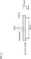
- the above mentioned flexural strength can be obtained in the three-point bending test even in a case where the load point is located at a position of the interlayer boundary (may be simply termed as "boundary" herein) in the fabrication method as later explained.
- Fig.1 schematically depicts a three-point bending test.
- the interlayer boundary which is produced by laminating zirconia powders of different compositions, is disposed at the center of the length (the midpoint in a longitudinal direction) of the test sample.
- the boundary extends along a direction of load application (along a direction of the smallest cross-sectional area) to traverse the test sample.
- the load point in the three-point bending test is aligned with the position of the boundary. Even in case the flexural strength is measured by a test which imposes a load on the boundary, it is possible to obtain a strength comparable to that of the sintered body which is not of a laminated (multi-layered) structure, i.e., a sintered body free of the boundary.
- the flexural strength measured as load is applied to the interlayer boundary is preferably not less than 90% and more preferably not less than 95% of the flexural strength of a local portion other than the boundary, (for example, the flexural strength of a pre-sintered body prepared from a non-laminated composition, under comparable conditions, e.g., same pre-sintering temperature ⁇ pre-sintering time).
- the fracture toughness of the zirconia sintered body according to the present invention is preferably not less than 3.5 MPa ⁇ m 1/2 , more preferably not less than 3.8 MPa ⁇ m 1/2 , more preferably not less than 4 MPa ⁇ m 1/2 and further preferably not less than 4.2 MPa ⁇ m 1/2 .
- these values are those obtained in the state prior to performing the hydrothermal treatment test.
- the boundary produced by laminating zirconia powders of different compositions is located at the center of the test sample (the midpoint in the longitudinal direction).
- the boundary extends along the load applying direction (along a direction with the smallest [cross-sectional] area direction) to traverse the test sample.
- the position of a diamond pressing tip used in the measurement test is aligned with the boundary.
- the zirconia sintered body of the present invention it is desirable for the zirconia sintered body of the present invention that the above values are satisfied for every item of the peak ratio of the monoclinic crystal after the hydrothermal treatment, flexural strength and the fracture toughness.
- the peak ratio of the monoclinic crystal after the hydrothermal treatment is not larger than unity(one)
- the fracture toughness is not less than 3.5 MPa ⁇ m 1/2
- the flexural strength is not less than 1000 MPa.
- the peak ratio of the monoclinic crystal after the hydrothermal treatment is not larger than 0.6
- the fracture toughness is not less than 4 MPa ⁇ m 1/2
- the flexural strength is not less than 1000 MPa.
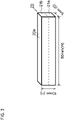
- Fig.2 depicts a schematic illustration for the zirconia sintered body. In the zirconia sintered body 10, shown in Fig.2 , it is desirable that the color is substantially not changed in a first direction X.
- the sintered body of the present invention changes in color, that is, presents color gradation, from one end to the opposite end.
- the increasing or decreasing tendency of the L* value, a* value and b* value is desirably not changed in the reverse direction. Viz., if, on the straight line extending from the one end P to the opposite end Q, the L* value tends to increase, it is desirable that there exists no domain where the L* value substantially decreases.
- the L* value tends to increase, it is desirable that there exists no domain where the L* value decreases by not less than unity, while it is more desirable that there exists no domain where the L* value decreases by not less than 0.5. If, on the straight line extending from the one end P to the opposite end Q, the a* value tends to decrease, it is desirable that there exists no domain where the a* value substantially increases.
- the a* value tends to decrease, it is desirable that there exists no domain where the a* value increases by unity or more, while it is more desirable that there exists no domain where the a* value increases by 0.5 or more.
- the b* value tends to decrease, it is desirable that there exists no domain where the b* value substantially increases.
- the b* value tends to decrease, it is desirable that there exists no domain where the b* value increases by unity or more, while it is more desirable that there exists no domain where the a* value increases by 0.5 or more.
- the color change direction in the zirconia sintered body 10 if the L* value tends to increase from the one end P to the opposite end Q, it is preferred that the a* and b* values tend to decrease. If, for example, the zirconia sintered body 10 is used as a dental prosthetic material, it is preferred that the color changes from pale yellow, pale orange or thin brown to white from the one end P to the opposite end Q.
- points on the straight line interconnecting one point P and the opposite end Q are labeled a first point A, a second point B, a third point C and a fourth point D, looking from the end P in order.
- the first point A is desirably in a domain of 25% to 45% of a length from the one point P to the opposite end Q (referred to below as 'total length') as measured from the one end P.
- the second point B is desirably in a domain from a site spaced a distance equal to 30% of the total length apart from the one point P up to a point of 70% from the one end P.
- the fourth point D is desirably in a domain of 25% to 45% of the total length from the opposite end Q.
- the third point C is desirably in a domain from a site spaced a distance equal to 30% of the total length apart from the opposite point Q up to a point of 70% of the total length from the opposite end Q.
- the chromaticity (L*, a*, b*) of the zirconia sintered body 10 in the L* a* b* color chromaticity diagram (JISZ8729) at the first point A, second point B, third point C and the fourth point D is expressed as (L1, a1, b1), (L2, a2, b2), (L3, a3, b3), (L4, a4, b4), respectively. It is desirable in this case that the following large/small relationship.
- the chromaticity of each point may be found by preparing a zirconia sintered body of the sole composition corresponding to each point and measuring the chromaticity of each such zirconia sintered body.
- L1 is desirably not less than 58.0 and not larger than 76.0.
- L2 is desirably not less than 62.5 and not larger than 80.5.
- L3 is desirably not less than 69.1 and not larger than 82.3.
- L4 is desirably not less than 71.8 and not larger than 84.2.
- a1 is desirably not less than -1.6 and not larger than 7.6.
- a2 is desirably not less than -1.8 and not larger than 5.5.
- a3 is desirably not less than -2.1 and not larger than 1.6.
- a4 is desirably not less than -2.1 and not larger than 1.8.
- b1 is desirably not less than 5.5 and not larger than 26.7.
- b2 is desirably not less than 4.8 and not larger than 21.8.
- b3 is desirably not less than 3.5 and not larger than 16.2.
- b4 is desirably not less than 1.9 and not larger than 16.0.
- L1 is not less than 60.9 and not larger than 72.5
- a1 is not less than 0.2 and not larger than 5.9
- b1 is not less than 11.5 and not larger than 24.9
- L4 is not less than 72.2 and not larger than 79.2
- a4 is not less than -1.2 and not larger than 1.7
- b4 is not less than 6.0 and not larger than 15.8.
- L1 is not less than 63.8 and not larger than 68.9
- a1 is not less than 2.0 and not larger than 4.1
- b1 is not less than 17.5 and not larger than 23.4
- L4 is not less than 72.5 and not larger than 74.1
- a4 is not less than -0.2 and not larger than 1.6
- b4 is not less than 10.1 and not larger than 15.6. This allows matching to the average color tone of teeth.
- the color difference ⁇ E*ab between two neighboring points may be expressed by the following equation.
- ⁇ L* is the difference between the L* values of two neighboring layers, such as (L1-L2).
- ⁇ a* is the difference between the a* values of two neighboring layers, such as (a1-a2).
- ⁇ b* is the difference between the b* values of two neighboring layers, such as (b1-b2).
- ⁇ E*ab 1 the color difference between the first point A and the second point B is ⁇ E*ab 1, that between the second point B and the third point C is ⁇ E*ab2 and that between the third point C and the fourth point D is ⁇ E*ab3, and the above mentioned relationship holds as to the chromaticity of each of the first point A, second point B, third point C and the fourth point D
- ⁇ E* abl for example, is desirably not less than 3.7 and not larger than 14.3.
- ⁇ E*ab2 is desirably not less than 1.8 and not larger than 17.9.
- ⁇ E*ab3 is desirably not less than 1.0 and not larger than 9.0. This can reproduce color changes similar to those of a natural tooth.
- ⁇ E * ab ⁇ L * 2 + ⁇ a * 2 + ⁇ b * 2
- ⁇ E*ab4 is desirably not larger than 36.
- a value obtained by deducting the color difference ⁇ E*ab4 between the first point A and the fourth point D from the sum of the color difference ⁇ E*ab1 between the first point A and the second point B, color difference ⁇ E*ab2 between the second point B and the third point C and the color difference ⁇ E*ab3 between the third point C and the fourth point D is desirably not larger than unity. This allows representing natural changes in color.
- the chromaticity of the fourth point D is in the above range
- a zirconia sintered body is prepared from solely the composition corresponding to the fourth point, and both surfaces of the sintered body are polished to a mirror surface to provide a sample of 0.5 mm in thickness
- the optical transmittance of the so prepared sample, as measured pursuant to JISK7361, is desirably not less than 27%.
- a zirconia sintered body is prepared from solely the composition corresponding to the first point, and both surfaces of the sintered body are polished to a mirror surface to a sample of 0.5 mm in thickness, the optical transmittance of the so prepared sample, as measured pursuant to JISK7361, is desirably not less than 10%.
- a length L of the zirconia sintered body 10 in a first direction Y satisfies a length corresponding to at least an exposed portion of a natural tooth.
- the length L of the zirconia sintered body 10 is preferably 5 mm to 18 mm.
- the composition as well as the pre-sintered body for the preparation of the zirconia sintered body of the present invention will now be explained.
- the composition as well as the pre-sintered body is a precursor (partly-finished product) of the zirconia sintered body of the present invention.
- the pre-sintered body is obtained on firing, that is, pre-sintering (may be termed "calcining", too) at a temperature below the sintering temperature.
- pre-sintered body encompasses a shaped product.
- a dental prosthesis such as a crown, obtained by milling, grinding and/or cutting a pre-sintered zirconia disc using the CAD/CAM (Computer-Sided Design/ Computer-Aided Manufacturing) may be included in the pre-sintered body.
- CAD/CAM Computer-Sided Design/ Computer-Aided Manufacturing
- composition as well as the pre-sintered body is prepared as zirconia powders of respective different compositions are laminated one on another.
- Each of the composition and the pre-sintered body contains zirconia crystal powders, mainly of the monoclinic system, a stabilizer(s) and titanium oxide.
- An aluminum oxide may be contained in the composition, too.
- aluminum oxide is ⁇ alumina.
- the average particle size of zirconia powder (in granulated state) in the composition is preferably 20 ⁇ m to 40 ⁇ m.
- oxides such as calcium (CaO), magnesium oxide (MgO), yttria or cerium oxide (CeO 2 ) may be given.
- the stabilizer(s) is added in such an amount as to allow the zirconia powder in the sintered body to be partially stabilized.
- the content of yttria is preferably 2.5 mol% to 4.5 mol%, more preferably 3 mol% to 4.5 mol% and further preferably 3.5 mol% to 4.5 mol%, relative to the total of mols of zirconia and yttria .
- the content of aluminum oxide in the composition as well as the pre-sintered body is preferably 0 mass% (no aluminum oxide content) to 0.3 mass% relative to the total mass of the zirconia crystal particles and the stabilizer(s) in order to elevate the strength of the zirconia sintered body. If the content of aluminum oxide exceeds 0.3 mass%, transmittance of the zirconia sintered body is lowered.
- the content of titanium oxide in the composition as well as the pre-sintered body is preferably 0 mass% (no titanium oxide content) to 0.6 mass% relative to the total mass of the zirconia crystal particles and the stabilizer(s) in order to promote growth of zirconia crystal grains. If the content of titanium oxide exceeds 0.6 mass%, strength of the zirconia sintered body is lowered.
- the content of silicon oxide in the composition as well as the pre-sintered body is preferably 0.1 mass% or less relative to the total mass of the zirconia crystal particles and the stabilizer(s).
- the composition as well as the pre-sintered body is substantially free of silicon oxide SiO 2 (silica). It is because the content of silicon oxide lowers the transmittance of the zirconia sintered body.
- substantially free of silicon oxide it is meant that silicon oxide is contained within a range not affecting the property or the characteristic of the present invention, or that silicon oxide is preferably contained in an amount not exceeding the level of the content of impurities. It is not necessarily meant that the silicon oxide content is to be lower than the limit of detection.
- the composition as well as the pre-sintered body according to the present invention may contain a pigment(s) for coloring. If the zirconia sintered body, prepared from the composition or the pre-sintered body, is used as the dental material, chromium oxide (Cr 2 O 3 ), erbium oxide (Er 2 O 3 ), iron oxide (Fe 2 O 3 ), praseodymium oxide (Pr 6 O 11 ) and so forth may be used as pigments, either alone or in combination. The contents of the pigments may partially be differentiated.
- a local portion from the bottom end to 25 % to 45% of the total thickness is a first layer
- a local portion from the top of the first layer to 5% to 25% of the total thickness is a second layer
- a local portion from the top of the second layer to 5 % to 25% of the total thickness is a third layer
- a local portion from the top of the third layer to an upper end, having a thickness corresponding to 25 % to 45% of the total thickness is a fourth layer, preferably the pigment content decreases from the first layer towards the fourth layer.
- erbium oxide and iron oxide may be added as pigment(s).
- the content of erbium oxide and the content of iron oxide in the first layer relative to the total mass of the zirconia and the stabilizer are preferably 0.33 mass% to 0.52 mass% and 0.05 mass% to 0.12 mass%, respectively.
- the content of erbium oxide and the content of iron oxide in the second layer relative to the total mass of the zirconia and the stabilizer are preferably 0.26 mass% to 0.45 mass% and 0.04 mass% to 0.11 mass%, respectively.
- the content of erbium oxide and the content of iron oxide in the third layer relative to the total mass of the zirconia and the stabilizer are preferably 0.05 mass% to 0.24 mass% and 0.012 mass% to 0.08 mass%, respectively.
- the content of erbium oxide and the content of iron oxide in the fourth layer relative to the total mass of the zirconia and the stabilizer are preferably 0 mass% to 0.17 mass% and 0 mass% to 0.07 mass%, respectively.
- the content of erbium oxide and the content of iron oxide decrease from the first layer towards the fourth layer in order.
- a sintered body prepared from a composition or a pre-sintered body is used as a dental material
- erbium oxide, iron oxide and chromium oxide may be added as the pigments.
- the sintered body prepared from the composition or the pre-sintered body is used as a dental material, it is preferred that, in the first layer, the content of erbium oxide, that of iron oxide and that of chromium oxide relative to the total mass of the zirconia and the stabilizer(s) are preferably 0.08 mass% to 0.37 mass%, 0.08 mass% to 0.15 mass% and 0.0008 mass% to 0.0012 mass%, respectively.
- the content of erbium oxide, that of iron oxide and that of chromium oxide relative to the total mass of the zirconia and the stabilizer(s) are preferably 0.06 mass% to 0.42 mass%, 0.06 mass% to 0.18 mass% and 0.0006 mass% to 0.001 mass%, respectively.
- the content of erbium oxide, that of iron oxide and that of chromium oxide relative to the total mass of the zirconia and the stabilizer(s) are preferably 0.06 mass% to 0.17 mass%, 0.018 mass% to 0.042 mass% and 0.0001 mass% to 0.0003 mass%, respectively.
- the content of erbium oxide, that of iron oxide and that of chromium oxide relative to the total mass of the zirconia and the stabilizer(s) are preferably 0 mass% to 0.12 mass%, 0 mass% to 0.001 mass% and 0 mass% to 0.0001 mass%, respectively. It is preferred that the content of erbium oxide, that of iron oxide and that of chromium oxide decrease from the first layer towards the fourth layer in order.
- a sintered body prepared from the composition or the pre-sintered body is used as a dental material
- erbium oxide, iron oxide and praseodymium oxide may be added as the pigments.
- the sintered body prepared from the composition or the pre-sintered body is used as a dental material, it is preferred that, in the first layer, the content of erbium oxide, that of iron oxide and that of praseodymium oxide relative to the total mass of the zirconia and the stabilizer(s) are preferably 0.08 mass% to 2.2 mass%, 0.003 mass% to 0.12 mass% and 0.003 mass% to 0.12 mass%, respectively.
- the content of erbium oxide, that of iron oxide and that of praseodymium oxide relative to the total mass of the zirconia and the stabilizer(s) are preferably 0.06 mass% to 1.9 mass%, 0.002 mass% to 0.11 mass% and 0.002 mass% to 0.11 mass%, respectively.
- the content of erbium oxide, that of iron oxide and that of praseodymium oxide relative to the total mass of the zirconia and the stabilizer(s) are preferably 0.018 mass% to 1 mass%, 0.008 mass% to 0.06 mass% and 0.0008 mass% to 0.06 mass%, respectively.
- the content of erbium oxide, that of iron oxide and that of praseodymium oxide relative to the total mass of the zirconia and the stabilizer(s) are preferably 0 mass% to 0.7 mass%, 0 mass% to 0.05 mass% and 0 mass% to 0.05 mass%, respectively. It is preferred that the content of erbium oxide, that of iron oxide and that of praseodymium oxide decrease from the first layer towards the fourth layer in order.
- the content of the pigment(s) can be theoretically calculated from the amount of its addition with respect to the total mass of the zirconia and the stabilizer(s) and from the fabrication method.
- the flexural strength of the pre-sintered body of the present invention is preferably not less than 38 MPa, more preferably not less than 40 MPa and further preferably not less than 42 MPa.
- the above mentioned flexural strength can be obtained. If the flexural strength is measured by the same bending test as that for the above mentioned sintered body, a flexural strength higher than that of the pre-sintered body prepared by simply laminating of powders (without applying vibration, for example) may be obtained. If the flexural strength is measured by a test which imposes load on the interlayer boundary, such strength comparable with that of a non-laminated, that is, interlayer boundary-free, pre-sintered body, may be obtained.
- the flexural strength measured under a load applied to the interlayer boundary is preferably not less than 90% and more preferably not less than 95% of the flexural strength as measured at a local portion other than the interlayer boundary, for example, the flexural strength of a pre-sintered body prepared from a non-laminated composition under comparable conditions, such as the same pre-sintering temperature and pre-sintering time.
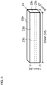
- Fig.3 and Fig.4 depict schematic views of a test sample used for measuring the extent of the deformation at the time of sintering.
- Fig.3 shows a schematic drawing of a two-layered lamination body.
- Fig.4 shows a schematic drawing of a four-layered lamination body.
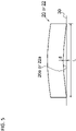
- Fig.5 depicts a schematic view for illustrating a method for measuring the extent of the deformation.
- a plurality of zirconia powders having respective different compositions, are laminated together to form a composition, and the composition is then fired (calcined) at 800°C to 1200°C for two hours to form a pre-sintered body.
- the pre-sintered body is then shaped by the CAD/ CAM system to a rectangular parallelepiped which is 50 mm in width[length], 10 mm in height and 5 mm in depth[thickness], as shown in Fig.3 and Fig.4 .
- This serves as a test sample.
- a test sample 20 that is a two-layered lamination body, shown in Fig.3 , has a first layer 21a and a second layer 21b.
- a test sample 22 that is a four-layered lamination body, shown in Fig.4 includes a first layer 23a, a second layer 23b, a third layer 23c and a fourth layer 23d.
- the thickness of the first layer 23a and that of the fourth layer 23d each account for 35% of the total thickness.
- the thickness of the second layer 23b and that of the third layer 23c each account for 15% of the total thickness. If, in each of the test samples 20, 22, the surface of 50 mm by 5 mm is supposed to be the bottom surface (upper or lower surface), each layer extends in the same direction as, preferably parallel to, the bottom surfaces 20a, 22a.
- each interlayer boundary is parallel to the bottom surfaces 20a, 22a.
- the test samples 20, 22 are set on a flat surface (ground surface 30) with the concave surface side directed downwards.
- the width of each of the as-deformed test samples 20, 22, that is, a distance L between the ground contacting points (fulcrum points) along the width, is measured.
- a gap d at the largest portion between the bottom surfaces 20a, 22a deformed to the concave shape and the ground surface 30 is measured.
- the extent(amount) of the deformation is calculated as (d/LX100).
- the deformation is preferably not larger than 0.15, more preferably not larger than 0.1, more preferably not larger than 0.05 and further preferably not larger than 0.03.
- Such a composition or a pre-sintered body, obtained on laminating zirconia powders of different compositions, is susceptible to deformation when subjected to sintering.
- the extent of the deformation can be made smaller than that in the composition or the pre-sintered body obtained on simple lamination.
- an end product can be improved in dimensional accuracy.
- the composition and the pre-sintered body according to the present invention can be applied to advantage to a dental prosthesis that may appreciably be different from person to person.
- a mixture layer presumed to have been formed on a boundary(interface) between neighboring (upper and lower) layers is not shown in Fig.3 or in Fig.4 for simplicity.
- the composition of the present invention may be powder, a fluid obtained on adding powders to a solvent, or a shaped body obtained on shaping the powders to a preset shape. That is, the composition may be powdery, or paste-like or wet composition. (In other words, the composition may be present in a solvent or contain a solvent.)
- the composition may also contain an additive(s), such as a binder(s) and pigment(s). By the way, the mass of the solvent and the additive such as the binder is not taken into account in calculating the content ratio.
- composition of the present invention is a shaped body
- the composition may be shaped by e.g., pressing, injection molding or stereolithography(or opto-molding). It may also be shaped by multistage shaping(forming).
- the composition of the present invention may be shaped by pressing followed by cold isostatic pressing (CIP).
- the pre-sintered body according to the present invention can be obtained by firing the composition of the present invention at 800°C to 1200°C under normal atmospheric pressure.
- the pre-sintered body of the present invention can be adapted to form the zirconia sintered body according to the present invention by being fired at 1350°C to 1600°C under normal atmospheric pressure.
- the length of the composition and the pre-sintered body along its laminating (i.e., layer-stacking) direction (thickness) is preferably determined so as to realize a targeted length of the sintered body as sintering shrinkage is taken into account.
- the targeted length along the laminating direction of the sintered body is 5 mm to 18 mm, as an example, while the length (thickness) along the laminating direction of the composition or the pre-sintered body may be set at 10 mm to 26 mm.
- zirconia and the stabilizer are wet-mixed together in water to form a slurry.
- the slurry is then dried and granulated.
- the resulting granules are then pre-sintered to form primary powders.
- the primary powders are divided into two groups. Then, a pigment(s) is added to at least one of the two groups of the primary powders to provide for difference in the ratio of pigment addition. For example, a pigment may be added to one of the groups, whereas no pigment may be added to the other.
- a powder (powder group) with a low addition ratio of a specified pigment is referred to below as “low addition ratio powder”
- a powder (powder group) with a high addition ratio of the specified pigment is referred to below as "high addition ratio powder”.
- the amount of pigment addition in the high addition ratio powder is preferably adapted to an addition ratio of a portion having darkest color in the sintered body.
- zirconia is mixed and pulverized in water to a desired particle size to form a zirconia slurry.
- the slurries are dried and granulated to form secondary powders.
- additive(s) such as aluminum oxide, titanium oxide and the binder, they may be added at the time of preparation of the primary powders or at the time of preparation of the secondary powders.
- a plurality of powders having respective different pigment contents are then prepared from the secondary powders of the low addition ratio powder and the high addition ratio powder.
- a first powder for the first layer may be made up of 100% of the high addition ratio powder without adding the low addition ratio powder.
- a second powder for the second layer may be prepared by mixing the low addition ratio powder and the high addition ratio powder at a mixing ratio of the low addition ratio powder to high addition ratio powder of 5:95 to 15:85.
- a third powder for the third layer may be prepared by mixing the low addition ratio powder and the high addition ratio powder at a mixing ratio of the low addition ratio powder to high addition ratio powder of 35:65 to 45:55.
- a fourth powder for the fourth layer may be prepared by mixing the low addition ratio powder and the high addition ratio powder at a mixing ratio of the low addition ratio powder to high addition ratio powder of 45:55 to 55:45.
- the first powder for the first layer may be made up of 100% of the high addition ratio powder without adding the low addition ratio powder.
- the second powder for the second layer may be prepared by mixing the low addition ratio powder and the high addition ratio powder at a mixing ratio of the low addition ratio powder to high addition ratio powder of 10:90 to 30:70.
- the third powder for the third layer may be prepared by mixing the low addition ratio powder and the high addition ratio powder at a mixing ratio of the low addition ratio powder to high addition ratio powder of 70:30 to 90:10.
- the fourth powder for the fourth layer may be made up of 100% of the low addition ratio powder without adding the high addition ratio powder.
- the difference between the mixing ratios for the second and third layers is preferably larger than that between the mixing ratios for the first and second layers as well as that between the mixing ratios for the third and fourth layers.
- the secondary powders may be divided into a number of groups corresponding to the number of the layers.
- a desired additive(s) may be added to each powder.
- a plurality of powders having respective different pigment contents are then laminated in order. If desired to impart color gradation to the sintered body, it is preferred that the powders are laminated so that the ratio of addition of a particular pigment becomes higher or lower stepwise in the sequence of layering.
- powder(s) of the first layer is charged into a mold and an upper surface of the powder(s) of the first layer is made flat. As a way of making it flat the upper surface of the powder(s), vibrating the mold or leveling the upper surface of the powder(s) of the first layer may be adopted. It is preferred not to perform pressing until the totality of the layers has been laminated.
- the powder(s) of the second layer is then charged on top of the powder(s) of the first layer.
- the mold is then vibrated so that the vibration is transmitted to the powders in the mold.
- a desired way such as giving a mechanical vibration to the mold, vibrating(or swinging) the mold manually and striking the mold with a hammer, for example, may be suitably adopted. It is thought that, by so doing, the powder(s) of the first layer and that of the second layer are partially mixed together at a boundary between the powders of the first and second layers.
- the number of times as well as intensity of the vibrations and, in the case of mechanical vibrations, the frequency and amplitude of the vibration may be appropriately set, depending on the particle size, particle size distribution or the particle shape, so that mixing of the powders of the upper and lower layers will take place on the interlayer boundary.
- the upper surface of the powder(s) of the second layer is then made flat as in the case of the powder(s) of the first layer. The sequence of operations is repeated until all of the layers are laminated.
- the first powder(s) is charged to a predetermined thickness, such as to 25% to 45% of the overall thickness. At this time, the upper surface of the first powder(s) is made flat, but pressing is not performed.
- the second powder(s) is then charged on the first powder(s) to a predetermined thickness, such as to 5 to 25% of the overall thickness.
- the mold is then vibrated. It is presumed that this vibration forms a first boundary layer, which is a mixture of the first and second powders, at a boundary between an upper surface of the first powder(s) and a lower surface of the second powder(s). The upper surface of the second powder is then made flat.
- Pressing is not applied to the second powder before charging the third powder.
- the third powders are charged on the second powder to a predetermined thickness, for example, to 25% to 45% of the overall thickness.
- the mold is then vibrated. It is presumed that this vibration forms a second boundary layer, which is a mixture of the second and third powders, at a boundary between an upper surface of the second powder(s) and a lower surface of the third powder(s).
- the upper surface of the third powder(s) is then made flat. Pressing the third powder(s) is not performed before charging the fourth powder(s).
- the fourth powder(s) is charged on the third powder(s) to a predetermined thickness, for example, to 25% to 45% of the overall thickness.
- the mold is then vibrated. It is presumed that this vibration forms a third boundary layer, which is a mixture of the third and fourth powders, at a boundary between an upper surface of the third powder(s) and a lower surface of the fourth powder(s).
- a shaped product as the composition of the present invention.
- the shaped product may then be subjected to CIP.
- the composition is fired at 1400°C to 1600°C and preferably at 1450 °C to 1550°C to sinter the zirconia powder(s) to fabricate the zirconia sintered body according to the present invention. Shaping to a desired shape may be performed in a stage of the shaped product.
- the composition is fired at 800 °C to 1200 °C to form a pre-sintered body.
- the pre-sintered body is then fired at 1400°C to 1600°C, preferably 1450°C to 1550°C to sinter the zirconia powder to fabricate the zirconia sintered body according to the present invention.
- Shaping may be performed by milling, grinding and/or cutting etc. in a stage of the pre-sintered body or following the sintering.
- the shaping may be carried out with the CAD/CAM system.
- the fabrication method for a dental prosthesis is similar to the above described fabrication method except that the pre-sintered or sintered body is shaped to the form of a crown.
- the composition, pre-sintered body and the sintered body in the form of a four-layered lamination structure, has been shown and explained.
- the number of layers may be other than four.
- the composition, pre-sintered body or the sintered body may, as an example, be formed with two layers, namely the first and fourth layers.
- the composition, pre-sintered body or the sintered body may, as an example, be formed with three layers, namely the first, second and fourth layers. It is noted that Fig.2 is only for facilitated explanation of the positional relationships and directions of respective points such that the shape and size are not limited to those shown in Fig.2 .
- a sintered body sample was fabricated from a composition prepared on laminating zirconia powders of respective different compositions and measurement was made of its flexural strength, chromaticity and extent of deformation.
- a zirconia powder containing a stabilizer was prepared. 7.2 mass% (4 mol%) of yttria, as stabilizer, were added to 92.8 mass% of mainly monoclinic zirconia powder. An alumina sol was added so that the amount of addition of alumina is 0.1 mass% to the powder mixture of zirconia and yttria (100 mass%). Then, 150 mass% of water, 0.2 mass% of an anti-foaming agent and 1 mass% of a dispersant were added to the powder mixture of zirconia and yttria (100 mass%). The resulting mixture was pulverized with a ball mill for 10 hours.
- the average particle size of a slurry obtained by pulverization (ballmilling) was 0.12 ⁇ m.
- the slurry was granulated, using a spray drier, and so formed granules were pre-sintered at 1000°C for two hours to prepare primary powder.
- the primary powder was divided into two groups, and a pigment was added to at least one of the groups.
- the powder of the group with a low pigment addition ratio is termed a "low addition ratio powder", and that of the group with a high pigment addition ratio is termed a "high addition ratio powder”.
- Table 1 shows the addition ratios of Examples 1 to 3.
- Table 4 shows the addition ratio of Example 4.
- the values shown in Tables 1 and 2 are those of addition ratios related to the amount of the powder mixture of zirconia and yttria (100 mass%).
- each powder 0.2 mass% of titania, 200 mass% of water, 0.2 mass% of an anti-foaming agent and 1 mass% of a dispersant were added to the powder mixture of zirconia and yttria (100 mass%).
- Each resulting mixture was pulverized with a ballmill for 15 hours.
- the average particle size of the slurry after the pulverization was 0.13 ⁇ m.
- 6 mass% of the binder and 0.5 mass% of a mold release agent were added to the slurry and mixed with a ball mill for 15 minutes.
- the resulting slurry was granulated by a spray drier to form secondary powders of the low addition ratio powder and the high addition ratio powder.
- the low addition ratio powder and the high addition ratio powder were then mixed in ratios shown in Tables 3 to 6 to form first to fourth powders.
- a shaped body sample was then prepared.
- 35 grs of the first powder was charged in a metal mold with an inside size of 82 mm by 25 mm and an upper surface of the first powder was swept.
- 15 grs of the second powder was then charged on the first powder and the metal mold was vibrated by a vibrator. An upper surface of the second powder was swept off to a flat surface.
- 15 grs of the third powder was then charged on the second powder and the metal mold was vibrated by the vibrator. An upper surface of the third powder was swept off to a flat surface.
- 35 grs of the fourth powder was then charged on the third powder and the metal mold was vibrated by the vibrator. An upper surface of the fourth powder was swept off to a flat surface.
- Example 2 was carried out in the same way as in Examples 1, 3 and 4 except that 50 grs of the first powder and 50 grs of the second powder were charged. An upper mold was then set and the powder mixture was subjected to primary press forming at a surface pressure of 200 kg/cm 2 for 90 seconds using a uniaxial pressing apparatus. The primary press shaped body sample was subjected to CIP shaping at 1500kg/cm 2 for five minutes to prepare a shaped body sample.
- the shaped body samples were then fired at 1000°C for two hours to form a pre-sintered body sample.
- the pre-sintered body samples were then formed to a shape of a dental crown using the CAD/CAM system (Katana system, Kuraray Noritake Dental Inc.).
- the pre-sintered body sample was then fired at 1500°C for two hours to form a sintered body sample.
- the length of the sintered body along the direction of laminating the first to fourth powders was 8 mm.
- the test sample was cut out so that the longitudinal direction was along the laminating direction.
- the boundary between the second and third layers was positioned at the center of the test sample, as shown in Fig.1 .
- the boundary extended along the direction of load application, i.e., along a direction of the least [cross-sectional] area, so as to traverse the test sample.
- the flexural strength was measured with the load point of the three-point bending test aligned with the boundary position. Table 7 shows measured results.
- the flexural strength of the pre-sintered body sample of Example 4 was 40 MPa or more, however, those of the Comparative Examples were not larger than 36 MPa. From this it is seen that imparting vibration at the time of laminating of the powders can lead to improved joining strength between the layers at the stage of the pre-sintered body sample.
- the flexural strength of the sintered body sample of Example 4 was not less than 1200 MPa, however, those of the Comparative Examples 1, 2 were less than 1100 MPa, thus lower by 100 MPa or more than in Example 4. It has turned out that the joining strength between the layers can be elevated for the sintered body sample as well.
- Fracture toughness was measured of the sintered body sample, fabricated in Example 4, in accordance with JISR1607.
- the position of the boundary in the test sample was the same as in the above mentioned flexural strength testing.
- the position of the pressing tip was aligned with the boundary between the second and third powders.
- the fracture toughness was 4.3 MPa ⁇ m 1/2 This value is similar to that of the fracture toughness of the sintered body sample fabricated without laminating, as taught in Example 9, shown below, thus indicating that deterioration in fracture toughness was not produced by laminating.
- test sample(s), described above and shown in Fig.3 and Fig.4 was fabricated from the pre-sintered body sample, fabricated by being pre-sintered at 1000°C for two hours as in Example 4, and was fired at 1500°C for two hours to measure the extent of deformation (d/LX100). The extent of the deformation was measured using the above mentioned measurement method.
- Comparative Example the same test sample(s) was prepared for each of Comparative Examples 1 and 2, as in the bending test, and the extent of deformation after sintering was measured. Table 4 shows test results.
- the extent of the deformation was 0.15 or larger.
- the extent of the deformation can be 0.05 or less, indicating that the extent of the deformation can be suppressed appreciably as compared to the Comparative Examples. It is thought from this that, by vibrating the composition at the time of layering the powders of different compositions, it is possible to suppress shrinkage deformation at the time of the sintering more satisfactorily.
- Comparative Examples 1 and 2 indicate that the extent of the deformation is smaller in Comparative Example 1. From this, it is thought that not performing pressing after charging each layer can lead to more effective suppression of shrinkage deformation at the time of the sintering.
- the color difference between the sintered body sample of the first layer and that of the second layer was 7 to 14.
- the color difference between the sintered body sample of the second layer and that of the third layer was 10 to 18.
- the color difference between the sintered body sample of the third layer and that of the fourth layer was 4 to 9.
- the color difference between the sintered body sample of the first layer and that of the fourth layer was 28 to 36.
- a value obtained by deducting the color difference between the sintered body sample of the first layer and that of the fourth layer from the sum of the color difference between the sintered body sample of the first layer and that of the second layer, the color difference between the sintered body sample of the second layer and that of the third layer and color difference between the sintered body sample of the third layer and that of the fourth layer was not larger than unity(one).
- Example 1 L* a* b* Sintered body of fourth powder 75.70 -1.45 5.68 Sintered body of third powder 71.75 -1.15 8.35 Sintered body of second powder 67.75 4.51 16.30 Sintered body of first powder 58.20 7.39 26.13 [Table 10]
- Example 2 L* a* b* Sintered body of second powder 75.70 -1.45 5.68 Sintered body of first powder 58.20 7.39 26.13
- Example 3 L* a* b* Sintered body of fourth powder 76.10 -1.42 5.85 Sintered body of third powder 71.27 0.86 11.22 Sintered body of second powder 63.03 5.25 21.75 Sintered body of first powder 58.20 7.35 26.50
- Example 4 L* a* b* Sintered body of fourth powder 83.95 -1.87 4.15 Sintered body of third powder 77.00 0.25 9.29 Sintered body of second powder 64.12 4.95 20.24 Sintered body of first powder
- Low addition ratio powder and high addition ratio powder were prepared by adding pigments at the rates shown in Table 14 to a powder mixture of zirconia and yttria (100 mass%) and a composition was prepared at the proportions shown in Table 15. From the composition, a sintered body sample was prepared in the same way as in Examples 1 to 4. Change in the value of b* of the L*a*b* color chromaticity diagram was measured along the laminating direction, that is, along the second direction Y in Fig.2 . Fig.6 depicts a schematic view of the prepared test sample and results of measurement.
- Fig.6 depicts a schematic view of the test sample, also showing the size and the measurement direction, and a lower part of Fig.6 a graph showing the results of measurement.
- the as-sintered test sample was fabricated so that the sample has a size of 20 mm by 20 mm by 1 mm after the sintering.
- the first layer was a local area where the first powders were charged, and the fourth layer was a local area where the fourth powders were charged.
- the b* value was measured, using a two-dimensional colorimeter RC-300 manufactured and sold by PaPaLaB Co.
- Fig.7 depicts a schematic view of the test sample and the results of measurement.
- the value of b* shows a flat profile at a center portion of each layer, and, in the interlayer boundary, the value of b* shows step-like acute changes. This is presumably due to the fact that the powders of the respective layers having different pigment compositions have been sintered independently of one another. From this it is seen that there lacks tidy (or smooth) gradation in the appearance of the test sample of Comparative Example 3.
- the value of b* shows a moderately rising tendency even at the center portion of each layer. No step-like changes in the value of b* may be shown at the interlayer boundary such that it is difficult to discern where the boundary is located.
- the boundary between the first and second layers and that between the third and fourth layers shows linear transition. From this it is seen that the appearance of the sintered body sample of the present invention presents smooth gradation. This result is thought to be ascribable to the fact that applying the vibration at the time of charging of the first to fourth powders causes the powders to be mixed between the adjacent layers in a region of the boundary between the upper and lower layer, and thus makes it smaller a difference in the pigment ratio between the adjacent layers. By the way, the value of b* is changed more acutely between the second and third layers than at other portions of the graph. This is presumably due to the marked difference in the contents of the pigment(s) between the second and third powders.
- Example 4 Erbium oxide /mass% Iron oxide/mass% Low addition ratio powder 0.15 0.05 High addition ratio powder 0.5 0.1
- Example 1 First powder Second powder Third powder Fourth powder Low addition ratio powder 0% 20% 80% 100% High addition ratio powder 100% 80% 20% 0%
- primary powder was prepared in the same way as in Examples 1 to 4.
- the primary powder was divided into four sets of powders, that is, first to fourth powders.
- pigments shown in the following Tables 6 to 16 were added to the powders.
- the numerical values, shown in the Tables represent values of the addition rates of the pigments to the powder mixture of zirconia and yttria (100 mass%).
- Secondary powders of the first to fourth powders were prepared in the same way as in Examples 1 to 4 except that the low addition ratio powder and the high addition ratio powder were not fabricated and that different values of the pigments are used.
- a shaped body sample was prepared in the same way as in Examples 1 to 4.
- the shaped body was then fired at 1000°C for two hours to form a pre-sintered body sample.
- the pre-sintered body sample was then shaped into a crown shape, using the CAD/CAM system (Katana system, Kuraray Noritake Dental Inc.).
- the pre-sintered body sample was then fired at 1500°C for two hours to form a sintered body sample.
- the length of the sintered body sample of the first to fourth powders along the layering direction was 8 mm.
- Example 6 Erbium oxide /mass% Iron oxide /mass% Praseodymi u m oxide/mas s % Chromium oxide/mas s % Fourth powder 0 0 0 0 Third powder 0.02 0.04 0 0.0002 Second powder 0.08 0.16 0 0.0008 First powder 0.10 0.20 0 0.0010
- Example 7 Erbium oxide /mass% Iron oxide /mass% Praseodymi um oxide/mass % Chromium oxide/mas s % Fourth powder 0 0 0 0 Third powder 0.1 0.02 0 0.0002 Second powder 0.4 0.08 0 0.0008 First powder 0.5 0.10 0 0.0010 [Table 18]
- Example 8 Erbium oxide /mass% Iron oxide/mass% Praseodymi um oxide/mass % Chromium oxide/mas s % Fourth powder 0.10 0 0 0 Third powder 0.15 0.026 0 0.0002 Second powder 0.30 0.104 0
- the chromaticity and the color difference of the sintered body samples of the first to fourth powders were measured in the same way as in Examples 1 to 4.
- Tables 26 to 35 show the values of chromaticity.
- Tables 36, 37 show the values of the color difference.
- chromaticity of each powder represents chromaticity of each point of the zirconia sintered body sample fabricated from layered body samples of a plurality of powders.
- the combination of the four sintered body samples of Example 9 presents bright color on the whole.
- the combination of the four sintered body samples of Example 10 presents dark color on the whole.
- L* was 58 to 76, a* was -2 to 8 and b* was 5 to 27.
- L* was 66 to 81, a* -2 to 6 and b* 4 to 21.
- L* was 69 to 83, a* -2 to 2 and b* 3 to 17.
- L* was 71 to 84, a* -2 to 1 and b* 2 to 15.
- the color difference between the sintered body sample of the first layer and that of the second layer was 3 to 15.
- the color difference between the sintered body sample of the second layer and that of the third layer was 1 to 11.
- the color difference between the sintered body sample of the third layer and that of the fourth layer was 1 to 4.
- the color difference between neighboring layers showed a decreasing tendency from the first layer towards the fourth layer.
- the color difference between the sintered body sample of the first layer and that of the fourth layer was 8 to 29.
- a value obtained by deducting the color difference between the sintered body sample of the first layer and that of the fourth layer from the sum of the color difference between the sintered body sample of the first layer and that of the second layer, the color difference between the sintered body sample of the second layer and that of the third layer and the color difference between the sintered body sample of the third layer and the fourth layer was not larger than unity.
- Example 6 L* a* b* Fourth powder 71.97 0.60 2.10 Third powder 70.36 0.61 4.44 Second powder 68.77 0.82 11.22 First powder 64.79 0.93 19.76 [Table 27]
- Example 7 L* a* b* Fourth powder 74.33 -0.75 5.24 Third powder 73.72 -0.63 6.35 Second powder 73.11 1.70 9.59 First powder 71.59 2.92 13.65
- Example 8 L* a* b* Fourth powder 71.97 0.60 2.10 Third powder 71.38 0.64 3.68 Second powder 70.80 1.37 8.27 First powder 69.35 1.76 14.04 [Table 29]
- Example 9 L* a* b* Fourth powder 73.79 -0.90 6.64 Third powder 73.30 -0.78 7.57 Second powder 72.81 1.65 10.26 First powder 71.59 2.92 13.65
- Example 10 L* a* b* Fourth powder 73.79 -0.90 6.64 Third powder 72.80 -0.82
- a zirconia sintered body sample was independently prepared from each of the first to fourth powders of Example 9 and the flexural strength, fracture toughness and the peak ratio of the monoclinic crystal following the hydrothermal treatment were measured. The results of measurement are shown in Table 38.
- the flexural strength of the zirconia sintered body sample was measured pursuant to JISR1601.
- the fracture toughness of the zirconia sintered body sample was measured pursuant to JISR1607.
- the hydrothermal treatment test was conducted pursuant to ISO 13356 under a condition of at 180 °C, 1 MPa for five hours.
- the X-ray diffraction pattern of the zirconia sintered body sample was measured, using CuKa rays, to measure the peak ratio of the monoclinic crystal, that is, the extent of phase transition to the monoclinic crystal caused by the hydrothermal treatment test.
- the flexural strength was not less than 1200 MPa
- the fracture toughness was not less than 4MPa ⁇ m 1/2
- the peak ratio of the monoclinic crystal was not larger than unity. It is thought that, since the zirconia sintered body samples of the other Examples are similar in composition, similar results would be obtained with these Examples. Test results of the flexural strength and the fracture toughness were similar to those obtained with the load applied to the boundary of the laminated body samples.
- the flexural strength of the pre-sintered body sample prepared by firing at 1000 °C for two hours, was also measured pursuant to JISR1601.
- the flexural strength of the sintered body sample of the second powder was 41 MPa. This value was similar to that obtained on testing under a load applied to the boundary of the laminated body samples.
- Samples for measurement Flexural strength/MPa Fracture toughness/MPa ⁇ m Peak ratio * of monoclinic crystal Sintered body of first powders 1210 4.3 0.58 Sintered body of second powders 1216 4.3 0.59 Sintered body of third powders 1204 4.3 0.60 Sintered body of fourth powders 1202 4.3 0.59
- Example 16 a sintered body sample with the yttria content of 3 mol% was prepared to measure the chromaticity. Except the yttria content, the sintered body sample used for measurement was the same as that of Example 4 shown in Tables 14 and 15. Table 39 shows measured results. Comparison with the chromaticity shown in Table 12 indicates that, if the yttria content is lowered, L* tends to decrease, while a* and b* tend to increase.
- Example 16 L* a* b* Sintered body of fourth powders 73.20 -1.35 5.72 Sintered body of third powders 69.78 0.42 9.84 Sintered body of second powders 59.52 5.75 22.20 Sintered body of first powders 56.10 7.52 26.32
- the zirconia sintered body as well as the composition and the pre-sintered body for the zirconia sintered body has been explained in the above exemplary embodiments. It should be noted however that the present invention is not limited to the above described exemplary embodiments and a variety of modifications, changes and improvements may be made of the elements herein disclosed, inclusive of elements of claims, exemplary embodiments and Examples as well as drawings, within the scope of the invention, based on the fundamental technical concept of the present invention. It is also possible to make a diversity of combinations, substitutions and selections of elements herein disclosed, inclusive of elements of claims, exemplary embodiments and Examples as well as drawings, within the scope of the invention.
- a zirconia pre-sintered body wherein,
- the zirconia pre-sintered body according to the supplementary note, wherein (the maximum gap between the deformed concave bottom surface and the ground surface)/(distance between the portions of the test sample contacting the ground surface along the widthwise direction) X 100 is 0.1 or less.
- the zirconia pre-sintered body according to the supplementary note wherein the plurality of zirconia powders contain a pigment(s) in respective different ratios.
- a method for preparing a zirconia composition comprising:
- the method for preparing the zirconia composition the supplementary note wherein, in the laminating step, the mold is vibrated each time one powder layer for lamination is charged into the mold.
- a method for preparing a zirconia composition comprising:
- a method for preparing a zirconia pre-sintered body comprising:
- a method for preparing a zirconia sintered body comprising:
- a method for preparing a zirconia sintered body comprising:
- the zirconia sintered body according to the present invention may be put to a variety of uses, including dental materials, such as prostheses, connection parts for optical fibers, such as ferrules and sleeves, a variety of tools, such as crushing balls and grinding tools, a variety of components, such as screws, bolts and nuts, a variety of sensors, electronic parts, and ornaments, such as watch bands.
- dental materials such as prostheses, connection parts for optical fibers, such as ferrules and sleeves, a variety of tools, such as crushing balls and grinding tools, a variety of components, such as screws, bolts and nuts, a variety of sensors, electronic parts, and ornaments, such as watch bands.
- dental material such as prostheses, connection parts for optical fibers, such as ferrules and sleeves, a variety of tools, such as crushing balls and grinding tools, a variety of components, such as screws, bolts and nuts, a variety of sensors, electronic parts, and ornaments, such as watch bands.
Applications Claiming Priority (3)
| Application Number | Priority Date | Filing Date | Title |
|---|---|---|---|
| JP2013100617 | 2013-05-10 | ||
| PCT/JP2014/062364 WO2014181827A1 (fr) | 2013-05-10 | 2014-05-08 | Corps fritté de zircone, composition de zircone, corps calciné de zircone, et prothèse dentaire |
| EP14794909.3A EP3006418B1 (fr) | 2013-05-10 | 2014-05-08 | Procede de fabrication d'un corps fritté de zircone |
Related Parent Applications (1)
| Application Number | Title | Priority Date | Filing Date |
|---|---|---|---|
| EP14794909.3A Division EP3006418B1 (fr) | 2013-05-10 | 2014-05-08 | Procede de fabrication d'un corps fritté de zircone |
Publications (1)
| Publication Number | Publication Date |
|---|---|
| EP3988517A1 true EP3988517A1 (fr) | 2022-04-27 |
Family
ID=51867304
Family Applications (2)
| Application Number | Title | Priority Date | Filing Date |
|---|---|---|---|
| EP14794909.3A Active EP3006418B1 (fr) | 2013-05-10 | 2014-05-08 | Procede de fabrication d'un corps fritté de zircone |
| EP21213862.2A Pending EP3988517A1 (fr) | 2013-05-10 | 2014-05-08 | Un corps pre-fritté de zircone |
Family Applications Before (1)
| Application Number | Title | Priority Date | Filing Date |
|---|---|---|---|
| EP14794909.3A Active EP3006418B1 (fr) | 2013-05-10 | 2014-05-08 | Procede de fabrication d'un corps fritté de zircone |
Country Status (6)
| Country | Link |
|---|---|
| US (4) | US10758326B2 (fr) |
| EP (2) | EP3006418B1 (fr) |
| JP (4) | JP6581903B2 (fr) |
| KR (2) | KR102089203B1 (fr) |
| CN (1) | CN105164084B (fr) |
| WO (1) | WO2014181827A1 (fr) |
Families Citing this family (28)
| Publication number | Priority date | Publication date | Assignee | Title |
|---|---|---|---|---|
| EP2829251B1 (fr) | 2013-07-22 | 2019-04-10 | Ivoclar Vivadent AG | Contrôle de la cinétique de frittage de céramiques oxydées |
| KR102613105B1 (ko) * | 2014-12-26 | 2023-12-12 | 쿠라레 노리타케 덴탈 가부시키가이샤 | 지르코니아 조성물, 지르코니아 가소체 및 지르코니아 소결체, 그리고 치과용 제품 |
| DE102015122865A1 (de) * | 2015-12-28 | 2017-06-29 | Degudent Gmbh | Verfahren zur Herstellung einer dentalen Restauration |
| DE102015122864A1 (de) * | 2015-12-28 | 2017-06-29 | Degudent Gmbh | Verfahren zur Herstellung eines Rohlings sowie dentale Restauration |
| DE102016106370A1 (de) * | 2016-03-23 | 2017-09-28 | Degudent Gmbh | Verfahren zur Herstellung eines eingefärbten Rohlings sowie Rohling |
| US10196313B2 (en) * | 2016-03-30 | 2019-02-05 | Daiichi Kigenso Kagaku Kogyo Co., Ltd. | Zirconia fine powder and production method therefor |
| EP3108849B1 (fr) | 2016-04-25 | 2019-04-24 | 3M Innovative Properties Company | Ébauche pour fraisage dentaire à zircone multicouche et procédé de production |
| WO2018056330A1 (fr) * | 2016-09-20 | 2018-03-29 | クラレノリタケデンタル株式会社 | Composition de zircone, objet calciné et compact fritté, et procédé de production associé |
| CN106514876B (zh) * | 2016-09-27 | 2018-03-09 | 淮阴工学院 | 氧化锆陶瓷的切削方法 |
| US20180098828A1 (en) * | 2016-10-07 | 2018-04-12 | 3M Innovative Properties Company | Ceramic dental restorations made by additive manufacturing |
| DE102016119935A1 (de) * | 2016-10-19 | 2018-04-19 | Degudent Gmbh | Verfahren zur Herstellung einer dentalen Restauration |
| EP3318218B1 (fr) | 2016-11-07 | 2019-09-11 | Shofu Inc. | Ébauche de zircone dentaire ayant une densité relative élevée |
| JP6151841B1 (ja) | 2016-11-28 | 2017-06-21 | 株式会社松風 | 30%の位置に中間色層を有する歯科用被切削体 |
| CN107175747B (zh) * | 2017-05-12 | 2020-04-07 | 爱迪特(秦皇岛)科技股份有限公司 | 强度、颜色均匀过渡的牙科氧化锆修复材料及其制备方法 |
| US10793475B2 (en) * | 2017-06-22 | 2020-10-06 | AAC Technologies Pte. Ltd. | Method for making housing for mobile communication device |
| KR102658087B1 (ko) * | 2017-07-31 | 2024-04-17 | 쿠라레 노리타케 덴탈 가부시키가이샤 | 지르코니아 입자 및 형광제를 포함하는 분말의 제조 방법 |
| CN110891921A (zh) * | 2017-07-31 | 2020-03-17 | 可乐丽则武齿科株式会社 | 包含荧光剂的氧化锆烧结体 |
| KR20190023440A (ko) | 2017-08-29 | 2019-03-08 | 한국광학기술 주식회사 | 치과용 레진 시멘트 |
| JP7213829B2 (ja) * | 2017-12-26 | 2023-01-27 | クラレノリタケデンタル株式会社 | 歯科用に好適なジルコニア仮焼体 |
| KR101961836B1 (ko) | 2018-05-10 | 2019-03-25 | 한전원자력연료 주식회사 | 순수 단사정계 지르코니아 소결체 및 이의 제조방법 |
| WO2020129918A1 (fr) * | 2018-12-19 | 2020-06-25 | クラレノリタケデンタル株式会社 | Corps fritté en zircone |
| JP7213268B2 (ja) * | 2018-12-27 | 2023-01-26 | クラレノリタケデンタル株式会社 | 歯科用に好適なジルコニア仮焼体 |
| KR20220002353A (ko) * | 2019-04-25 | 2022-01-06 | 쿠라레 노리타케 덴탈 가부시키가이샤 | 치과용으로 바람직한 지르코니아 가소체 및 그 제조 방법 |
| FR3108904B1 (fr) * | 2020-04-03 | 2023-04-07 | Saint Gobain Ct Recherches | Billes frittees de zircone |
| EP4177234A1 (fr) * | 2020-07-01 | 2023-05-10 | Kuraray Noritake Dental Inc. | Corps calciné en zircone approprié pour un usage dentaire |
| US11672632B2 (en) | 2020-10-05 | 2023-06-13 | Pritidenta Gmbh | Multi-layered zirconia dental blank with reverse layers, process for its preparation and uses thereof |
| CN112250438B (zh) * | 2020-10-16 | 2022-11-25 | 江西德锆美瓷有限公司 | 一种高均匀性全瓷义齿用氧化锆瓷块的制备方法及其制品 |
| CN116477941B (zh) * | 2023-04-19 | 2024-02-23 | 中物院成都科学技术发展中心 | 一种人工玉陶及其制备方法 |
Citations (2)
| Publication number | Priority date | Publication date | Assignee | Title |
|---|---|---|---|---|
| DE102006024489A1 (de) * | 2006-05-26 | 2007-11-29 | Forschungszentrum Karlsruhe Gmbh | Grünkörper, Verfahren zur Herstellung einer Keramik und deren Verwendung |
| US20070292597A1 (en) * | 2006-05-23 | 2007-12-20 | Ivoclar Vivadent Ag | Process for the preparation of colored blanks and dental shaped parts |
Family Cites Families (30)
| Publication number | Priority date | Publication date | Assignee | Title |
|---|---|---|---|---|
| JPH01197421A (ja) | 1988-02-03 | 1989-08-09 | Shiseido Co Ltd | 色調の変化する粉末化粧料の製造方法 |
| JPH05318431A (ja) * | 1992-05-21 | 1993-12-03 | Toshiba Corp | 傾斜機能材料の製造方法 |
| JPH0624940A (ja) | 1992-07-10 | 1994-02-01 | Noevir Co Ltd | 色調の変化する粉体化粧料の製造方法 |
| JP3384513B2 (ja) * | 1994-11-02 | 2003-03-10 | 東陶機器株式会社 | 傾斜機能材料を用いた電子管の封止構造 |
| JP2004035332A (ja) * | 2002-07-03 | 2004-02-05 | Advance Co Ltd | セラミックスブロック |
| JP2004181520A (ja) | 2002-12-06 | 2004-07-02 | Hitachi Metals Ltd | 超硬合金製圧延用複合ロール |
| DE10261720A1 (de) * | 2002-12-30 | 2004-07-15 | Meyer, Gerhard, Prof. Dr. | Fräskeramiken aus Metalloxid-Pulvern mit bimodaler Korngrößenverteilung |
| JP4238976B2 (ja) * | 2003-03-19 | 2009-03-18 | Toto株式会社 | 多孔質セラミックスの製造方法およびそれを製造するための成形装置 |
| ATE309182T1 (de) * | 2003-06-13 | 2005-11-15 | 3M Espe Ag | Gleichmässig gefärbte gerüstkeramik sowie färbelösung |
| JP3881647B2 (ja) | 2003-10-07 | 2007-02-14 | 住友チタニウム株式会社 | 多結晶シリコンロッド及びその製造方法 |
| EP1791491A1 (fr) * | 2004-09-14 | 2007-06-06 | Oratio B.V. | Procede de fabrication et d'installation d'un implant dentaire ceramique avec une partie d'appui d'implant esthetique |
| EP1900341B1 (fr) | 2006-09-13 | 2011-05-04 | Ivoclar Vivadent AG | Corps moulé multicolore |
| US8173562B2 (en) * | 2006-05-23 | 2012-05-08 | Ivoclar Vivadent Ag | Shaded zirconia ceramics |
| EP2083744A4 (fr) * | 2006-11-09 | 2013-08-28 | Univ New York | Structures alternées de verre/zircone/verre à gradient pour prothèses dentaires et orthopédiques en céramique résistantes aux altérations |
| WO2009042110A1 (fr) * | 2007-09-21 | 2009-04-02 | New York University School Of Medicine | Structures à base de zircone de qualité bioactive |
| US8834161B2 (en) * | 2009-03-04 | 2014-09-16 | Innovationspatent Sverige Ab | Zirconium dioxide based prostheses |
| EP2263991A1 (fr) * | 2009-06-19 | 2010-12-22 | Nobel Biocare Services AG | Revêtement d'application dentaire |
| US8877664B2 (en) | 2009-08-21 | 2014-11-04 | Noritake Co., Limited | Zirconia sintered body, and mixture, pre-sintered compact and pre-sintered calcined body for sintering zirconia sintered body |
| JP5399949B2 (ja) * | 2010-03-02 | 2014-01-29 | 株式会社ノリタケカンパニーリミテド | ジルコニア焼結体、ジルコニア組成物及びジルコニア仮焼体 |
| JP5718599B2 (ja) | 2010-08-20 | 2015-05-13 | 株式会社ノリタケカンパニーリミテド | ジルコニア焼結体、並びにその焼結用組成物及び仮焼体 |
| CN102285795A (zh) | 2011-05-30 | 2011-12-21 | 北京大学口腔医学院 | 牙科复色可切削氧化锆陶瓷及制备方法 |
| EP2529694B1 (fr) * | 2011-05-31 | 2017-11-15 | Ivoclar Vivadent AG | Procédé de génération de formes en céramique par jet d'impression 3D |
| EP4011852A1 (fr) * | 2011-07-29 | 2022-06-15 | Tosoh Corporation | Poudre mélangée, granules de poudre à granulation par pulvérisation et corps vert pour utilisation dans la production de corps fritté en zircone translucide coloré |
| US8936848B2 (en) * | 2012-02-23 | 2015-01-20 | B&D Dental Corp | Non-pre-colored multi-layer zirconia dental blank that has a gradual change in translucency through a thickness after sintering |
| US10391671B2 (en) * | 2012-04-16 | 2019-08-27 | Vita Zahnfabrik H. Rauter Gmbh & Co. Kg | Process for producing a non-dense sintered ceramic molded body having at least two layers |
| US10315958B2 (en) * | 2012-06-20 | 2019-06-11 | Ivoclar Vivadent Ag | CeO2-stabilized ZrO2 ceramics for dental applications |
| CN102875147B (zh) | 2012-10-17 | 2013-11-20 | 安泰科技股份有限公司 | 氧化锆陶瓷材料及其制备方法 |
| KR101276616B1 (ko) * | 2013-03-05 | 2013-06-19 | 주식회사 디맥스 | 색상 구배를 갖는 인공치아용 지르코니아 블록의 제조방법 |
| JP6352593B2 (ja) * | 2013-05-02 | 2018-07-04 | クラレノリタケデンタル株式会社 | ジルコニア焼結体、ジルコニア組成物及びジルコニア仮焼体、並びに歯科用補綴物 |
| EP3151782B1 (fr) * | 2014-06-06 | 2018-12-26 | 3M Innovative Properties Company | Dispositif de fabrication additive à base de poudre pour articles dentaires |
-
2014
- 2014-05-08 EP EP14794909.3A patent/EP3006418B1/fr active Active
- 2014-05-08 KR KR1020187029511A patent/KR102089203B1/ko active IP Right Grant
- 2014-05-08 JP JP2015515890A patent/JP6581903B2/ja active Active
- 2014-05-08 CN CN201480026434.7A patent/CN105164084B/zh active Active
- 2014-05-08 US US14/890,259 patent/US10758326B2/en active Active
- 2014-05-08 WO PCT/JP2014/062364 patent/WO2014181827A1/fr active Application Filing
- 2014-05-08 KR KR1020157034752A patent/KR101909673B1/ko active IP Right Grant
- 2014-05-08 EP EP21213862.2A patent/EP3988517A1/fr active Pending
-
2019
- 2019-09-02 JP JP2019159203A patent/JP6841880B2/ja active Active
-
2020
- 2020-07-28 US US16/940,909 patent/US11045292B2/en active Active
-
2021
- 2021-02-18 JP JP2021023844A patent/JP7277495B2/ja active Active
- 2021-05-27 US US17/331,934 patent/US20210282907A1/en active Pending
- 2021-05-27 US US17/331,977 patent/US20210282908A1/en active Pending
-
2023
- 2023-05-08 JP JP2023076564A patent/JP2023101533A/ja active Pending
Patent Citations (2)
| Publication number | Priority date | Publication date | Assignee | Title |
|---|---|---|---|---|
| US20070292597A1 (en) * | 2006-05-23 | 2007-12-20 | Ivoclar Vivadent Ag | Process for the preparation of colored blanks and dental shaped parts |
| DE102006024489A1 (de) * | 2006-05-26 | 2007-11-29 | Forschungszentrum Karlsruhe Gmbh | Grünkörper, Verfahren zur Herstellung einer Keramik und deren Verwendung |
Also Published As
| Publication number | Publication date |
|---|---|
| KR20180115351A (ko) | 2018-10-22 |
| JP6841880B2 (ja) | 2021-03-10 |
| JP2023101533A (ja) | 2023-07-21 |
| EP3006418A4 (fr) | 2017-04-12 |
| US20200352687A1 (en) | 2020-11-12 |
| JP2019206476A (ja) | 2019-12-05 |
| JP7277495B2 (ja) | 2023-05-19 |
| US11045292B2 (en) | 2021-06-29 |
| EP3006418A1 (fr) | 2016-04-13 |
| US10758326B2 (en) | 2020-09-01 |
| KR102089203B1 (ko) | 2020-03-13 |
| WO2014181827A1 (fr) | 2014-11-13 |
| JP6581903B2 (ja) | 2019-09-25 |
| JP2021080166A (ja) | 2021-05-27 |
| KR20160006200A (ko) | 2016-01-18 |
| US20210282907A1 (en) | 2021-09-16 |
| CN105164084A (zh) | 2015-12-16 |
| KR101909673B1 (ko) | 2018-10-18 |
| US20210282908A1 (en) | 2021-09-16 |
| JPWO2014181827A1 (ja) | 2017-02-23 |
| US20160081777A1 (en) | 2016-03-24 |
| CN105164084B (zh) | 2017-05-03 |
| EP3006418B1 (fr) | 2022-01-05 |
Similar Documents
| Publication | Publication Date | Title |
|---|---|---|
| US11045292B2 (en) | Zirconia sintered body, zirconia composition, zirconia pre-sintered body and dental prosthesis | |
| US10512527B2 (en) | Zirconia sintered body, zirconia composition, zirconia pre-sintered body and preparing method thereof, and dental prosthesis | |
| KR101615002B1 (ko) | 지르코니아 소결체, 지르코니아 조성물 및 지르코니아 가소체, 그리고 치과용 보철물 | |
| JP6189627B2 (ja) | ジルコニア焼結体、ジルコニア組成物及びジルコニア仮焼体、並びに歯科用補綴物 | |
| JP6615262B2 (ja) | ジルコニア仮焼体及びジルコニア焼結体 | |
| JP6346360B2 (ja) | ジルコニア焼結体、ジルコニア組成物及びジルコニア仮焼体、並びに歯科用補綴物 | |
| JP7139407B2 (ja) | ジルコニア仮焼体及びジルコニア焼結体並びに積層体 | |
| JP2020045282A (ja) | ジルコニア焼結体 | |
| JP2018168062A (ja) | ジルコニア焼結体 |
Legal Events
| Date | Code | Title | Description |
|---|---|---|---|
| PUAI | Public reference made under article 153(3) epc to a published international application that has entered the european phase |
Free format text: ORIGINAL CODE: 0009012 |
|
| STAA | Information on the status of an ep patent application or granted ep patent |
Free format text: STATUS: THE APPLICATION HAS BEEN PUBLISHED |
|
| AC | Divisional application: reference to earlier application |
Ref document number: 3006418 Country of ref document: EP Kind code of ref document: P |
|
| AK | Designated contracting states |
Kind code of ref document: A1 Designated state(s): AL AT BE BG CH CY CZ DE DK EE ES FI FR GB GR HR HU IE IS IT LI LT LU LV MC MK MT NL NO PL PT RO RS SE SI SK SM TR |
|
| STAA | Information on the status of an ep patent application or granted ep patent |
Free format text: STATUS: REQUEST FOR EXAMINATION WAS MADE |
|
| 17P | Request for examination filed |
Effective date: 20221021 |
|
| RBV | Designated contracting states (corrected) |
Designated state(s): AL AT BE BG CH CY CZ DE DK EE ES FI FR GB GR HR HU IE IS IT LI LT LU LV MC MK MT NL NO PL PT RO RS SE SI SK SM TR |
|
| P01 | Opt-out of the competence of the unified patent court (upc) registered |
Effective date: 20230523 |
|
| STAA | Information on the status of an ep patent application or granted ep patent |
Free format text: STATUS: EXAMINATION IS IN PROGRESS |