EP3978419B1 - Hubmechanismus für ein automatisch geführtes fahrzeug und automatisch geführtes fahrzeug - Google Patents
Hubmechanismus für ein automatisch geführtes fahrzeug und automatisch geführtes fahrzeug Download PDFInfo
- Publication number
- EP3978419B1 EP3978419B1 EP20814304.0A EP20814304A EP3978419B1 EP 3978419 B1 EP3978419 B1 EP 3978419B1 EP 20814304 A EP20814304 A EP 20814304A EP 3978419 B1 EP3978419 B1 EP 3978419B1
- Authority
- EP
- European Patent Office
- Prior art keywords
- connecting rod
- lifting
- module
- shaft
- lifting mechanism
- Prior art date
- Legal status (The legal status is an assumption and is not a legal conclusion. Google has not performed a legal analysis and makes no representation as to the accuracy of the status listed.)
- Active
Links
Images


Classifications
-
- B—PERFORMING OPERATIONS; TRANSPORTING
- B66—HOISTING; LIFTING; HAULING
- B66F—HOISTING, LIFTING, HAULING OR PUSHING, NOT OTHERWISE PROVIDED FOR, e.g. DEVICES WHICH APPLY A LIFTING OR PUSHING FORCE DIRECTLY TO THE SURFACE OF A LOAD
- B66F9/00—Devices for lifting or lowering bulky or heavy goods for loading or unloading purposes
- B66F9/06—Devices for lifting or lowering bulky or heavy goods for loading or unloading purposes movable, with their loads, on wheels or the like, e.g. fork-lift trucks
- B66F9/063—Automatically guided
-
- B—PERFORMING OPERATIONS; TRANSPORTING
- B66—HOISTING; LIFTING; HAULING
- B66F—HOISTING, LIFTING, HAULING OR PUSHING, NOT OTHERWISE PROVIDED FOR, e.g. DEVICES WHICH APPLY A LIFTING OR PUSHING FORCE DIRECTLY TO THE SURFACE OF A LOAD
- B66F7/00—Lifting frames, e.g. for lifting vehicles; Platform lifts
- B66F7/06—Lifting frames, e.g. for lifting vehicles; Platform lifts with platforms supported by levers for vertical movement
- B66F7/0633—Mechanical arrangements not covered by the following subgroups
-
- B—PERFORMING OPERATIONS; TRANSPORTING
- B66—HOISTING; LIFTING; HAULING
- B66F—HOISTING, LIFTING, HAULING OR PUSHING, NOT OTHERWISE PROVIDED FOR, e.g. DEVICES WHICH APPLY A LIFTING OR PUSHING FORCE DIRECTLY TO THE SURFACE OF A LOAD
- B66F9/00—Devices for lifting or lowering bulky or heavy goods for loading or unloading purposes
- B66F9/06—Devices for lifting or lowering bulky or heavy goods for loading or unloading purposes movable, with their loads, on wheels or the like, e.g. fork-lift trucks
- B66F9/075—Constructional features or details
Definitions
- the present disclosure relates to the field of an automated guided vehicle, and specifically to a lifting mechanism of an automated guided vehicle and an automated guided vehicle.
- the automated guided vehicle is a transport vehicle that is equipped with electromagnetic or optical automated guided devices, can travel along a defined guidance path, and has safety protection and various transfer functions.
- the automated guided vehicle is required to have a certain lifting capacity, so as to lift the carried goods to a predetermined height.
- CN Patent Application Publication No. CN109264628A discloses an AGV lifting alignment system according to the preamble of claim 1.
- the system comprises a bottom plate, a lifting mechanism, a driving mechanism, a lifting top plate, a lifting positioning block, an upper aligning device and a proximity switch sensor;
- the lifting positioning block is installed on the lifting top plate, and positioning holes of which the shape is adapted to the lifting positioning block are formed in the upper aligning device;
- the proximity switch sensor is fixedly integrated with the lifting positioning block;
- the lifting mechanism includes a first lifting plate, a second lifting plate,a lifting thrust plate, a screw mechanism, a first fixed block, a second fixed block, a first rolling ball bearing, a first bearing rolling plate, a second rolling ball bearing, a second bearing rolling plate and a connecting shaft.
- the system has simple structure, is easy to prepare, and can achieve precise alignment with a shelf.
- CN Patent No. CN207002119U discloses a carrier comprising an elevating platform, for solving the problem of laying a handled load easily on a cargo platform.
- This carrier with an elevating platform comprises a base that has wheels, a base platform being located above the base, the base platform being connected to the base by an elevating system.
- the cargo platform comprises a fixed platform and a movable platform, the fixed platform is connected to the base platform by a connecting piece, so that the fixed platform is fixed relative to the base platform, an opening is arranged in the fixed platform, and the movable platform is located in said opening, the movable platform is connected with the base platform through a second elevating system, said second elevating system can drive the moving platform up and down, so that the moving platform's upper surface can move below the fixed platform's upper surface.
- the disclosed utility model can be used for the transport of objects.
- US Patent Application Publication No. US20090104007A1 discloses an automated guided vehicle for loading and unloading a rotary press with various types and widths of rolls of newsprint or other paper irrespective of their diameters.
- the vehicle has a traveling carriage for automatically transporting a newsprint between a storage area and the setting area in a rotary press machine. It includes a hoisting/lower unit which hoists and lowers the newsprint in the vertical direction into and away from registering with the paper holding arms of the rotary press machine.
- the hoisting/lowering unit includes two hoisting/lowering frames parallel to a traveling road surface, and the central axis between the fixed and movable paper holding arms of the rotary press paper. The frames are kept spaced apart by an arc-shaped connecting member. Linear guides on upper surfaces of the two hoisting/lowering frames slidably support a moving table bridging over the linear guide 144 which supports the roll and permits the supported roll to be axially displaced into engagement with the support cones of the fixed holding
- a lifting mechanism of an automated guided vehicle includes: a carrier tray; a base plate; a connecting rod module connected between the carrier tray and the base plate; and a lifting module, which is arranged on the base plate, connected to the connecting rod module and located on one side of the connecting rod module and configured to cause the carrier tray to translate along a first direction by means of driving the connecting rod module; wherein the first direction is a lifting direction of the lifting module lifting the connecting rod module or a direction opposite to the lifting direction; and the lifting module comprises: a first power source; a lifting bracket connected to the connecting rod module; and a transmission assembly having an input end connected to the first power source and an output end connected to the lifting bracket, configured to transmit power outputted by the first power source to the lifting bracket, so that the lifting bracket drives the connecting rod module to translate along the first direction; the first power source comprises a geared motor, and the transmission assembly comprises: an intermediate shaft having a hollow structure, wherein an axis of the intermediate shaft is parallel to the first
- the transmission assembly further includes: a first gear connected to an output end of the first power source; and a second gear fixedly connected to the first end of the intermediate shaft and meshing with the first gear.
- the lifting module further includes: a case, which at least partially accommodates the transmission assembly and is fixedly connected to the first power source to realize integrated assembling and disassembling of the lifting module.
- a first stepped hole and a second stepped hole having different sizes are provided inside the case, the intermediate shaft has a first stepped shaft section and a second stepped shaft section having different sizes, and the transmission assembly further including: a first tapered roller bearing arranged between the first stepped hole and the first stepped shaft section, and supporting the first end of the intermediate shaft along a radial direction; a second tapered roller bearing arranged between the second stepped hole and the second stepped shaft section, and supporting the second end of the intermediate shaft along the radial direction and an axial direction; and a locking retainer ring fixedly arranged at the first end of the intermediate shaft, and supporting the first tapered roller bearing along the axial direction.
- the transmission assembly further includes: a first dust-proof ring being in interference fit with an outer cylindrical surface of the locking retainer ring, and in clearance fit with the first tapered roller bearing and the case respectively; and a second dust-proof ring arranged on the case, and located on one side of the second tapered roller bearing adjacent to the lifting bracket.
- the lifting module further includes: a slide rail fixedly arranged on the lifting bracket, wherein an extending direction of the slide rail is parallel to the first direction; and a guided block arranged on the case and fitted over the slide rail, wherein a cross-sectional shape of the guided block nestedly matched with a cross-sectional shape of the slide rail so as to guide the slide rail to move along the first direction.
- the slide rails is two slide rails
- the guided block is two guided blocks
- the two guided blocks are matched with the two slide rails respectively
- the two slide rails are arranged symmetrically
- the axis of the lead screw is located on a symmetry plane of the two slide rails
- the case includes: two guided block fixing lugs symmetrically arranged on both sides of the case and respectively connected to the two guided blocks.
- the case includes: an electric motor fixing lug fixedly connected to a housing of the first power source, and configured to cause an axis of the output shaft of the first power source to be parallel to the first direction, and cause the axis of the output shaft of the first power source is located on the symmetry plane.
- the lifting mechanism further includes: a rotary module arranged between the connecting rod module and the carrier tray, and configured to drive the carrier tray to rotate relative to the connecting rod module.
- the rotary module includes: a rotary support inner ring fixedly arranged on one side of the connecting rod module adjacent to the carrier tray; and a rotary support outer ring fixedly arranged on one side of the carrier tray adjacent to the connecting rod module and rotatably supported on the rotary support inner ring.
- the rotary support outer ring includes an outer ring gear
- the rotary module further includes: a second power source fixedly arranged on the connecting rod module; and a third gear, which is in transmission connection with an output end of the second power source, and configured to drive the carrier tray to rotate by meshing with the outer gear ring.
- the connecting rod module includes: an upper mounting plate configured to support the carrier tray; an intermediate frame arranged parallel to the upper mounting plate; a first connecting rod assembly arranged between the upper mounting plate and the intermediate frame, and configured to change a distance between the upper mounting plate and the intermediate frame; and a second connecting rod assembly arranged between the intermediate frame and the base plate, and configured to change a distance between the intermediate frame and the base plate.
- the first connecting rod assembly includes: a first connecting rod having a first end hinged to the upper mounting plate through a first hinge shaft, and a second end hinged to the intermediate frame through a second hinge shaft;
- the second connecting rod assembly includes: a second connecting rod having a first end hinged to the intermediate frame through a third hinge shaft, and a second end hinged to the base plate through a fourth hinge shaft;
- the second hinge shaft and the third hinge shaft are arranged coaxially, so that the second end of the first connecting rod is hinged at the same position of the intermediate frame as the first end of the second connecting rod;
- the first connecting rod has the same length as the second connecting rod, and axes of the first hinge shaft, the second hinge shaft, the third hinge shaft, and the fourth hinge shaft are parallel to each other; and
- the connecting rod module is connected to the lifting module through the first hinge shaft, and an orthographic projection of the axis of the first hinge shaft overlaps with an orthographic projection of the axis of the fourth hinge shaft on the base plate during a process
- the intermediate frame includes: a first groove arranged on one end of the intermediate frame and penetrating through the one end of the intermediate frame along a vertical direction, and forming a first accommodating space with the first connecting rod assembly (33) and the second connecting rod assembly (34); and a second groove arranged on one end of the intermediate frame away from the first groove and penetrating through the one end of the intermediate frame away from the first groove along the vertical direction, and forming a second accommodating space with the first connecting rod assembly (33) and the second connecting rod assembly (34); wherein orthographic projections of the first connecting rod assembly and the second connecting rod assembly on the base plate do not overlap with orthographic projections of the first groove and the second groove on the base plate during a process of driving the connecting rod module by the lifting module.
- the lifting mechanism further includes: a photoelectric sensor arranged on the connecting rod module, and configured to detect a distance of the carrier tray relative to the base plate.
- a photoelectric sensor arranged on the connecting rod module, and configured to detect a distance of the carrier tray relative to the base plate.
- the relevant automated guided vehicles known to the inventors usually perform lifting operations in a lifting manner such as lead screws, slide rails or wedge blocks.
- the relevant automated guided vehicle uses the form of jacking by a plurality of lead screws, the goods placed on the top of the plurality of lead screws are lifted smoothly by synchronously adjusting the height of the plurality of lead screws.
- the form of jacking by a plurality of lead screws it is possible to cause the lead screw to bear the axial force whilst further bearing the radial force under the condition of vehicle travelling or unbalanced loading of the goods, which does not conform to the standard operation specifications of the lead screw so that it is easily to lead to failure of the lead screw assembly due to improper use.
- it is more difficult to synchronously adjust the height of the plurality of lead screws and there may be a slip-off risk of the goods if the height adjustment process is slightly asynchronous.
- some automated guided vehicles use the form of jacking by hollow lead screws, smoothly carry the carried goods and increase the radial force bearing capacity of the lead screw by using a large shaft diameter of the hollow screw.
- the precision of the hollow lead screw which increases the machining difficulty and the machining cost.
- the hollow lead screw has a certain radial force bearing capacity, it is still possible to cause damage to the structure of the lead screw if the lead screw is subjected to a radial force for a long time during the use.
- the components thereof related to lifting occupy more space and also require more auxiliary devices, which causes the automated guided vehicles to be in a high cost as a whole and inconvenient to be assembled and disassembled.
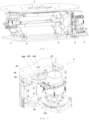
- a lifting mechanism of an automated guided vehicle includes: a carrier tray 1; a base plate 2; a connecting rod module 3, which is connected between the carrier tray 1 and the base plate 2 and is capable of causing the carrier tray 1 to translate along a first direction; and a lifting module 4, which is arranged on the base plate 2, connected to the connecting rod module 3 and located on one side of the connecting rod module 3 and capable of causing the carrier tray 1 to translate by means of driving the connecting rod module 3; wherein the first direction is the lifting direction of the lifting module 4 lifting the connecting rod module 3 or a direction opposite to the lifting direction.
- the lifting mechanism is integrally mounted on the automated guided vehicle through the upper carrier tray 1 and the lower base plate 2, so as to provide the automated guided vehicle with the function of raising or lowering the carrier height.
- the connecting rod module 3 controls the direction of the translational movement of the carrier tray 1, and then drives the connecting rod module 3 by means of the lifting module 4, thereby making the bearing function and the power function of the lifting module 4 independent from each other, and further reducing failure of the lifting structure that might be caused by the unbalanced loading of the carried object.
- the lifting module 4 in the related art usually simultaneously assumes the bearing function and the power function, that is, it is not only required to support the carrier tray 1 but also required to control the height of the position of the carrier tray 1.
- the lifting module 4 in the related art will simultaneously bear a load in a vertical direction and a moment perpendicular to a vertical direction. Take a kinematic pair of the lead screw 433 and the lead nut 432 commonly used in the lifting module 4 as an example.
- the lead screw 433 in the lifting module 4 will simultaneously bear the axial force caused by the load in a vertical direction, and the radial force caused by the moment perpendicular to a vertical direction.
- the radial force is very harmful to the lead screw 433 that is required to bear the load and the movement, which is easily to cause damage to the structure of the lead screw 433, thereby easily leading to the overall failure of the lifting structure.
- Fig. 1 is a schematic view of the overall structure of a lifting mechanism of an automated guided vehicle according to some embodiments of the present disclosure. It should be noted that, as shown in Fig. 1 , the translation direction of the carrier tray 1 is vertically upward or downward, and the lifting direction of the lifting module 4 to the connecting rod module 3 is vertically upward, that is, the first direction is a vertical direction at this time. However, for those skilled in the art, for the requirements in different lifting direction, the first direction which is not limited to a vertical direction, may have a certain angle with the vertical direction.
- the connecting rod module 3 is correspondingly configured to translate the carrier tray 1 along the corresponding first direction, and the driving force of the lifting module 4 to the connecting rod module 3 may also have the same included angle with the vertical direction accordingly.
- the first direction having a certain angle with the vertical direction as a translation direction of the carrier tray 1, the lifting mechanism can meet a larger number of more complex goods handling scenarios and requirements, and therefore has wider applicability.
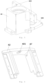
- Fig. 2 is a schematic structural view of a lifting module of an automated guided vehicle according to some embodiments of the present disclosure.
- the lifting module 4 includes: a first power source 41; a lifting bracket 42, which is connected to the connecting rod module 3; and a transmission assembly 43 having an input end connected to the first power source 41 and an output end is connected to the lifting bracket 42, which is capable of transmitting the power output by the first power source 41 to the lifting bracket 42, so that the lifting bracket 42 drives the connecting rod module 3 to translate along the first direction.
- a lifting bracket 42 is further provided between the lifting module 4 and the connecting rod module 3 to connect the lifting module 4 and the connecting rod module 3, and only transmit the radial force (that is, the load along the first direction) to the lifting module 4.
- the first power source 41 is drive-connected to the lifting bracket 42 through the transmission assembly 43, so that the lifting force is conducted to the carrier tray 1 through the lifting bracket 42.
- the lifting bracket 42 is driven in the form of a translational movement, and the first power source 41 usually outputs power by a rotational movement, in the present application, the power of the input end of the transmission assembly 43 is further transmitted to the output end thereof, whilst converting the power form into the power form corresponding to the lifting bracket 42.
- Fig. 3 is a schematic cross-sectional structure view of a lifting module of an automated guided vehicle according to some embodiments of the present disclosure.
- the first power source 41 is a geared motor
- the transmission assembly 43 includes: an intermediate shaft 431 having a hollow structure, wherein an axis the intermediate shaft 431 is parallel to the first direction, and a first end of the intermediate shaft 431 is connected to an output end of the geared motor; a lead nut 432 rotatably arranged inside the hollow structure and fixedly connected to a second end of the intermediate shaft 431; and a lead screw 433 threadedly engaged with the lead nut 432, and having one end connected to the lifting bracket 42, wherein an axis of the lead screw 433 is parallel to the first direction, so as to convert a rotational movement of the lead nut 432 into a translational movement of the lifting bracket 42 along the first direction.
- the first power source 41 is preferably a geared motor, that is, an integrated power source that contains the function of a reducer and the function of an electric motor, and can directly provide the transmission assembly 43 with the rated rotation speed required by the transmission assembly 43 as an output power.
- the transmission assembly 43 should be at least capable of converting the rotational movement output by the geared motor into the translational movement required by the lifting bracket 42.
- the transmission assembly 43 is preferably a power pair of a lead nut 432 and a lead screw 433, which can drive the lead screw 433 by means of the rotational movement of the lead nut 432.
- the lead nut 432 is threaded matched with the lead screw 433, the rotational movement is converted into the translational movement of the lead screw 433.
- the transmission assembly 43 introduces an intermediate shaft 431 as a power connection member between the lead nut 432 and the geared motor. That is, one end of the intermediate shaft 431 with a certain length is connected to the geared motor, the other end is connected to the lead nut 432.
- the intermediate shaft 431 has a hollow structure, so that the lead nut 432 is accommodatably mounted inside the hollow structure of the intermediate shaft 431; and the lead screw 433 is accommodated inside the lead nut 432, and external thread of the lead screw 433 and the internal thread of the lead nut 432 are mated each other.
- the axis of the lead screw 433 is parallel to the first direction. Then, during the power conversion process of the transmission assembly 43, the rotational movement of the lead nut 432 is converted into a translational movement of the lifting bracket 42 along the first direction.
- the transmission assembly 43 further includes: a first gear 411, which is connected to the output end of the first power source 41; and a second gear 434, which is fixedly connected to the first end of the intermediate shaft 431 and meshes with the first gear 411.
- Fig. 2 is a schematic structural view of a lifting module of an automated guided vehicle according to some embodiments of the present disclosure.
- the lifting module 4 further includes: a case 44, which at least partially accommodates the transmission assembly 43 and is fixedly connected to the first power source 41 to realize the integrated assembling and disassembling of the lifting module 4.
- Fig. 3 is a schematic cross-sectional structure view of a lifting module of an automated guided vehicle according to some embodiments of the present disclosure.
- a first stepped hole 441 and a second stepped hole 442 having different sizes are provided inside the case, the intermediate shaft 431 has a first stepped shaft section 431a and a second stepped shaft section 431b having different sizes.
- the transmission assembly 43 further includes: a first tapered roller bearing 435, which is arranged between the first stepped hole 441 and the first stepped shaft section 431a, and supports the first end of the intermediate shaft 431 along the radial direction; a second tapered roller bearing 436, which is arranged between the second stepped hole 442 and the second stepped shaft section 431b, and supports the second end of the intermediate shaft 431 along the radial direction and the axial direction; and a locking retainer ring 437, which is fixedly arranged at the first end of the intermediate shaft 431 and capable of supporting the first tapered roller bearing 435 along the axial direction.
- first stepped hole 441 and second stepped hole 442 are respectively provided inside the case 44 and outside the intermediate shaft 431.
- the outer circumferential surface of the first end of the intermediate shaft 431 is provided with threads, so that the locking retainer ring 437 may be fixedly mounted to the intermediate shaft 431 in a detachable manner in the form of threaded mating.
- the transmission assembly 43 further includes: a first dust-proof ring 438 which is in interference fit with an outer cylindrical surface of the locking retainer ring 437, and in clearance fit with the first tapered roller bearing 435 and the case 44 respectively; and a second dust-proof ring 439, which is arranged on the case 44 and located on one side of the second tapered roller bearing 436 adjacent to the lifting bracket 42.
- the intermediate shaft 431 in order to further reduce the volume of the transmission assembly 43, includes: a first hollow shaft cavity 431c and a second hollow shaft cavity 431d, which are arranged along the axis of the intermediate shaft 431.
- the second hollow shaft cavity 431d communicates with the first hollow shaft cavity 431c, and the inner diameter of the second hollow shaft cavity 431d is greater than the inside diameter of the first hollow shaft cavity and the circumscribed circle diameter of the lead nut 432.
- the intermediate shaft 431 with a two-section cavity structure having a first hollow shaft cavity 431c and a second hollow shaft cavity 431d
- the lifting module 4 when the lifting module 4 is not in a lifting state, it is possible to allow that portions of the lead nut 432 and the lead screw 433 adjacent to the lifting bracket 42 are provided within the second hollow shaft cavity 431d, and in a lifting state, the lead screw 433 will extend from the lead nut 432, to adequately release a length of the portion that is initially provided within the first hollow shaft cavity 431c , thereby providing a sufficient lifting stroke for the lifting module 4.
- Fig. 6 is a schematic structural view of a lifting bracket of an automated guided vehicle according to some embodiments of the present disclosure.
- a screw fixing hole 421 is provided at the junction between the lifting bracket 42 and the lead screw 433. The screw fixing hole 421 can accommodate the lead screw 433 and restrict the rotation of the lead screw 433.
- Fig. 2 is a schematic structural view of a lifting module of an automated guided vehicle according to some embodiments of the present disclosure
- Fig. 4 is a schematic structural view of a top view angle of a lifting module of an automated guided vehicle according to some embodiments of the present disclosure. As shown in Figs.
- the lifting module 4 further includes: a slide rail 45, which is fixedly arranged on the lifting bracket 42, wherein an extending direction of the slide rail 45 is parallel to the first direction; and a guided block 46, which is arranged on the case 44 and fitted over the slide rail 45, wherein the guided block 46 has a cross-sectional shape nestedly matched with the cross-sectional shape of the slide rail 45 so as to guide the slide rail 45 to move along the first direction.
- the load on the lifting bracket 42 along other directions than the first direction will be transferred to the case 44 by the guided block 46 and the slide rail 45, thereby reducing the radial force borne by the lead screw 433.
- the slide rails 45 is two slide rails 45
- the guided block is two guided blocks 46.
- the two guided blocks 46 are matched with the two slide rails 45 respectively, and the two slide rails 45 are arranged symmetrically, and the axis of the lead screw 433 is located on the symmetry plane 451 of the two slide rails 45.
- the case 44 includes: two guided block fixing lugs 443, which are symmetrically arranged on both sides of the case 44 and connected to the two guided blocks 46 respectively.
- the case 44 includes: an electric motor fixing lug 444, which is fixedly connected to the housing of the first power source 41, and configured to cause that an axis of the output shaft of the first power source 41 to be parallel to the first direction, and cause the axis of the output shaft of the first power source 41 is located on the symmetry plane 451.
- Fig. 9 is a schematic structural view of a rotary module of an automated guided vehicle according to some embodiments of the present disclosure.
- the lifting mechanism further includes: a rotary module 5, which is arranged between the connecting rod module 3 and the carrier tray 1, and capable of driving the carrier tray 1 to rotate relative to the connecting rod module 3.
- the rotary module 5 includes: a rotary support inner ring 51, which is fixedly arranged on one side of the connecting rod module 3 adjacent to the carrier tray 1; and a rotary support outer ring 52, which is fixedly arranged on one side of the carrier tray 1 adjacent to the connecting rod module 3 and rotatably supporting the rotary support inner ring 51.
- the rotary support inner ring 51 and the rotary support outer ring 52 are fixedly arranged on the connecting rod assembly and the carrier tray 1 respectively and rotatably connected therebetween to realize the rotatable connection of the carrier tray 1 relative to the connecting rod assembly.
- the rotary support between the rotary support inner ring 51 and the rotary support outer ring 52 may be implemented in view of ball bearings.
- the rotary support outer ring 52 includes an outer ring gear
- the rotary module 5 further includes: a second power source 53, which is fixedly arranged on the connecting rod module 3; and a third gear 54, which is in transmission connection with the output end of the second power source 53 and capable of driving the carrier tray 1 to rotate by meshing with the outer gear ring.
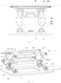
- Fig. 8 is a schematic structural view of a connecting rod module of an automated guided vehicle according to some embodiments of the present disclosure.
- the connecting rod module 3 includes: an upper mounting plate 31 for supporting the carrier tray 1; an intermediate frame 32, which is arranged parallel to the upper mounting plate 31; a first connecting rod assembly 33, which is arranged between the upper mounting plate 31 and the intermediate frame 32, and capable of changing a distance between the upper mounting plate 31 and the intermediate frame 32; and a second connecting rod assembly 34, which is arranged between the intermediate frame 32 and the base plate 2, and capable of changing a distance between the intermediate frame 32 and the base plate 2.
- the connecting rod assembly takes the form that two stages of connecting rods are sandwiched among three layers of planes (the carrier tray 1 - the first connecting rod assembly 33 - the intermediate frame 32 - the second connecting rod assembly 34 - the base plate 2), which not only ensures the overall stability of the connecting rod assembly by the intermediate frame 32, but also allowing the connecting rod module 3 to have sufficient telescopic space by the two stages of connecting rod assemblies.
- the first connecting rod assembly 33 includes: a first connecting rod 331 having a first end hinged to the upper mounting plate 31 through a first hinge shaft 332, and a second end hinged to the intermediate frame 32 through a second hinge shaft 333.
- the second connecting rod assembly 34 includes: a second connecting rod 341 having a first end hinged to the intermediate frame 32 through a third hinge shaft 342, and a second end hinged to the base plate 2 through a fourth hinge shaft 343.
- the first connecting rod 331 or the second connecting rod 341 which is hingedly mounted to the carrier tray 1, the intermediate frame 32 or the base plate 2 can change the distance among three layers of planes in such a manner as to rotate about the hinge point, thereby changing the distance between the upper mounting plate 31 of the connecting rod module 3 and the base plate 2.
- the first connecting rod assembly 33 and the second connecting rod assembly 34 may also change the distance between the upper mounting plate 31 and the base plate 2 in the form of a telescopic connecting rod.
- the connecting rod in the hinged and rotatable form has a simple structure, so that the connecting rod module 3 has a small overall volume, and the hinged connecting rod may also transmit a moment, so that it is possible to transfer a reflection moment caused by the unbalanced loading of the goods or the acceleration/deceleration of the automated guided vehicle from the upper mounting plate to the base plate 2. In this way, the deflection moment is not exerted on other functional modules of the automated guided vehicle, thereby improving the overall structural reliability of the vehicle.
- the second hinge shaft 333 and the third hinge shaft 342 are arranged coaxially, so that the second end of the first connecting rod 331 is hinged at the same position of the intermediate frame 32 as the first end of the connecting rod 341.
- the second hinge shaft 333 and the third hinge shaft 342 that are coaxially arranged in a group are jointly hingedly mounted on the intermediate frame 32, so that only one corresponding hinge hole is required to be provided on the intermediate frame 32, and one corresponding hinge pin/shaft and one corresponding shaft clip are only provided to simplify the structure of the intermediate frame 32.
- the first connecting rod 331 has the same length as the second connecting rod 341, and the axes of the first hinge shaft 332, the second hinge shaft 333, the third hinge shaft 342, and the fourth hinge shaft 343 are parallel to each other.
- first hinge shaft 332, the second hinge shaft 333, the third hinge shaft 342, and the fourth hinge shaft 343 are arranged to be parallel to each other, so that the rotation planes of the first connecting rod 331 and the second connecting rod 341 are parallel or coplanar.
- first connecting rod 331 and the second connecting rod 341 having the same length may have trajectory circles of the same radius length, with the second hinge point and the third hinge point as the centers of circle respectively.
- the connecting rod module 3 is connected to the lifting module 4 through the first hinge shaft 332.
- the orthographic projection of the axis of the first hinge shaft 332 on the base plate 2 overlaps with the orthographic projection of the axis of the fourth hinge shaft 343 on the base plate 2.
- the rotation planes of the first connecting rod 331 and the second connecting rod 341 are parallel or coplanar, and the first connecting rod 331 and the second connecting rod 341 may have trajectory circles of the same radius length, with the second hinge point and the third hinge point as the centers of circle respectively, when the connecting rod module 3 is connected to the lifting module 4 through the first hinge shaft 332, and the lifting direction of the lifting module 4 is along a straight line, the orthographic projections of the axis of the first hinge shaft 332 and the axis of the fourth hinge shaft 343 on the base plate 2 can overlap with each other, so as to ensure that the upper mounting plate 31 and the base plate 2 remain parallel to each other during the process of driving the connecting rod module 3 by the lifting module 4.
- the first connecting rod 331 is at least three first connecting rods 331 having the same length and arranged parallel to each other
- the second connecting rods 341 is at least three second connecting rods 341 having the same length and arranged parallel to each other.
- the lifting mechanism further includes: a rotary module 5, which is fixed to the connecting rod module 3 and capable of driving the carrier tray 1 to rotate in a horizontal plane.
- the intermediate frame 32 includes: a first groove 321 arranged on one end of the intermediate frame 32 and penetrating through one end of the intermediate frame 32 along the vertical direction for accommodating the lifting module 4; and a second groove 332 arranged on one end of the intermediate frame 32 away from the first groove 321 and penetrating through the one end of the intermediate frame 32 away from the first groove 321 along the vertical direction for accommodating the rotary module 5.
- the orthographic projections of the first connecting rod assembly 33 and the second connecting rod assembly 34 on the base plate 2 do not overlap with the orthographic projections of the first groove 321 and the second groove 332 on the base plate 2.
- the first groove 321 and the second groove 332 form accommodating spaces on both sides of the connecting rod assembly with the connecting rod assembly respectively, thereby providing sufficient space for the lifting module 4 and the rotary module 5, so that the lifting module 4, the rotary module 5, and the connecting rod module 3 are together accommodated within the space area corresponding to the base plate 2 in a relatively compact positional relationship, thereby further allowing an overall modularization and a miniaturized volume of the lifting mechanism.
- the lifting mechanism further includes: a photoelectric sensor 6, which is arranged on the connecting rod module 3 for detecting the distance of the carrier tray 1 relative to the base plate 2.
- an automated guided vehicle includes the lifting mechanism according to any of the foregoing embodiments.
- the lifting mechanism provided by the embodiments of the present disclosure can at least reduce failure of the lifting structure caused by the unbalanced loading of the carried object.
Landscapes
- Engineering & Computer Science (AREA)
- Structural Engineering (AREA)
- Transportation (AREA)
- Life Sciences & Earth Sciences (AREA)
- Geology (AREA)
- Mechanical Engineering (AREA)
- Civil Engineering (AREA)
- Platform Screen Doors And Railroad Systems (AREA)
- Warehouses Or Storage Devices (AREA)
- Transmission Devices (AREA)
Claims (15)
- Hebemechanismus für ein automatisch geführtes Fahrzeug, umfassend:eine Tragplatte (1);eine Grundplatte (2);ein Verbindungsstangenmodul (3), das zwischen der Tragplatte (1) und der Grundplatte (2) gekoppelt ist; undein Hubmodul (4), das auf der Grundplatte (2) angeordnet ist, mit der Tragplatte (3) verbunden und auf einer Seite des Verbindungsstangenmoduls (3) angeordnet und so konfiguriert ist, dass die Tragplatte (1) durch Antrieb des Verbindungsstangenmoduls (3) in eine erste Richtung verschoben wird;wobei die erste Richtung eine Hubrichtung des das Verbindungsstangenmodul (3) anhebenden Hubmoduls (4) oder eine der Hubrichtung entgegengesetzte Richtung ist; und wobei das Hubmodul (4) umfasst:eine erste Energiequelle (41);eine Hebehalterung (42), die mit dem Verbindungsstangenmodul (3) verbunden ist; undeine Getriebeanordnung (43) mit einem mit der ersten Energiequelle (41) verbundenen Eingangsende und einem mit der Hebehalterung (42) verbundenen Ausgangsende, die so konfiguriert ist, dass sie eine von der ersten Energiequelle (41) abgegebene Leistung an die Hebehalterung (42) überträgt, so dass die Hebehalterung (42) das Verbindungsstangenmodul (3) antreibt, um in die erste Richtung zu verschieben;dadurch gekennzeichnet, dassdie erste Energiequelle (41) einen Getriebemotor umfasst, und die Getriebeanordnung (43) umfasst:eine Zwischenwelle (431) mit einer hohlen Struktur, wobei eine Achse der Zwischenwelle (431) parallel zur ersten Richtung verläuft und ein erstes Ende der Zwischenwelle (431) mit einem Ausgangsende des Getriebemotors verbunden ist;eine Spindelmutter (432), die innerhalb der Hohlstruktur drehbar angeordnet und fest mit einem zweiten Ende der Zwischenwelle (431) verbunden ist; undeine Leitspindel (433), die in die Spindelmutter (432) eingeschraubt ist und mit deren einem Ende die Hebehalterung (42) verbunden ist, wobei eine Achse der Leitspindel (433) parallel zur ersten Richtung verläuft, um eine Drehbewegung der Spindelmutter (432) in eine translatorische Bewegung der Hebehalterung (42) entlang der ersten Richtung umzuwandeln;wobei die Zwischenwelle (431) umfasst:einen ersten Hohlwellenhohlraum (431c) und einen zweiten Hohlwellenhohlraum (431d), die entlang der Achse der Zwischenwelle (431) angeordnet sind,wobei der zweite Hohlwellenhohlraum (431d) mit dem ersten Hohlwellenhohlraum (431c) in Verbindung steht und ein Innendurchmesser des zweiten Hohlwellenhohlraums (431d) größer ist als sowohl der Innendurchmesser des ersten Hohlwellenhohlraums (431c) als auch ein Umkreisdurchmesser der Spindelmutter (432);wobei ein neben der Hebehalterung (42) befindlicher Teil der Leitspindel (433) in die Spindelmutter (432) eingepasst ist und ein von der Hebehalterung (42) entfernter Teil in den ersten Hohlwellenhohlraum (431c) eingepasst ist, wenn das Hubmodul (4) nicht angehoben ist.
- Hebemechanismus nach Anspruch 1, wobei die Getriebeanordnung (43) ferner umfasst:ein erstes Zahnrad (411), das mit einem Ausgangsende der ersten Energiequelle (41) verbunden ist; undein zweites Zahnrad (434), das mit dem ersten Ende der Zwischenwelle (431) fest verbunden ist und mit dem ersten Zahnrad (411) im Eingriff steht;und wobei optional an einer Verbindungsstelle zwischen der Hebehalterung (42) und der Leitspindel (433) ein Schraubenbefestigungsloch (421) vorgesehen ist, wobei das Schraubenbefestigungsloch (421) die Leitspindel (433) aufnimmt und eine Drehung der Leitspindel (433) einschränkt.
- Hebemechanismus nach Anspruch 1, wobei das Hubmodul (4) ferner umfasst:
ein Gehäuse (44), welches die Getriebeanordnung (43) zumindest teilweise aufnimmt und mit der ersten Energiequelle (41) fest verbunden ist, um einen integrierten Auf- und Abbau des Hubmoduls (4) zu realisieren. - Hebemechanismus nach Anspruch 3, wobei im Inneren des Gehäuses eine erste Stufenbohrung (441) und eine zweite Stufenbohrung (442) mit unterschiedlichen Größen vorgesehen sind, wobei die Zwischenwelle (431) einen ersten abgestuften Wellenabschnitt (431a) und einen zweiten abgestuften Wellenabschnitt (431b) mit unterschiedlichen Größen aufweist, und wobei die Getriebeanordnung (43) ferner umfasst:ein erstes Kegelrollenlager (435), das zwischen der ersten Stufenbohrung (441) und dem ersten Stufenwellenabschnitt (431a) angeordnet ist und das erste Ende der Zwischenwelle (431) entlang einer radialen Richtung der Zwischenwelle (431) stützt;ein zweites Kegelrollenlager (436), das zwischen der zweiten Stufenbohrung (442) und dem zweiten Stufenwellenabschnitt (431b) angeordnet ist und das zweite Ende der Zwischenwelle (431) entlang der radialen Richtung und einer axialen Richtung der Zwischenwelle (431) stützt; undeinen Sicherungsring (437), der am ersten Ende der Zwischenwelle (431) fest angeordnet ist und das erste Kegelrollenlager (435) in der axialen Richtung stützt.
- Hebemechanismus nach Anspruch 4, wobei die Getriebeanordnung (43) ferner umfasst:einen ersten staubdichten Ring (438), der mit einer äußeren zylindrischen Oberfläche des Sicherungsrings (437) in Presspassung ist und mit dem ersten Kegelrollenlager (435) bzw. dem Gehäuse (44) in Spielpassung ist; undeinen zweiten staubdichten Ring (439), der auf dem Gehäuse (44) angeordnet ist und sich auf einer Seite des zweiten Kegelrollenlagers (436) neben der Hebehalterung (42) befindet.
- Hebemechanismus nach Anspruch 4, wobei das Hubmodul (4) ferner umfasst:eine Gleitschiene (45), die fest an der Hebehalterung (42) angeordnet ist, wobei eine Ausfahrrichtung der Gleitschiene (45) parallel zur ersten Richtung verläuft; undeinen geführten Block (46), der auf dem Gehäuse (44) angeordnet und über der Gleitschiene (45) angebracht ist, wobei eine Querschnittsform des geführten Blocks (46) und eine Querschnittsform der Gleitschiene (45) aufeinander abgestimmt sind, um die Gleitschiene (45) so zu führen, dass sie sich entlang der ersten Richtung bewegt.
- Hebemechanismus nach Anspruch 6, wobei die Gleitschiene (45) aus zwei Gleitschienen (45) besteht, der geführte Block (46) aus zwei geführten Blöcken (46) besteht, wobei die beiden geführten Blöcke (46) jeweils an die beiden Gleitschienen (45) angepasst sind, die beiden Gleitschienen (45) symmetrisch angeordnet sind, und die Achse der Leitspindel (433) auf einer Symmetrieebene (451) der beiden Gleitschienen (45) angeordnet ist;
wobei das Gehäuse (44) umfasst:
zwei Führungsblock-Befestigungslaschen (443), die symmetrisch auf beiden Seiten des Gehäuses (44) angeordnet und jeweils mit den beiden geführten Blöcken (46) verbunden sind. - Hebemechanismus nach Anspruch 6, wobei das Gehäuse (44) umfasst:
eine Befestigungslasche (444) für Elektromotoren, die fest mit einem Gehäuse der ersten Energiequelle (41) verbunden und so konfiguriert ist, dass eine Achse der Ausgangswelle der ersten Energiequelle (41) parallel zur ersten Richtung verläuft und die Achse der Ausgangswelle der ersten Energiequelle (41) auf der Symmetrieebene (451) angeordnet ist. - Hebemechanismus nach Anspruch 1, ferner umfassend:
ein Drehmodul (5), das zwischen dem Verbindungsstangenmodul (3) und der Tragplatte (1) angeordnet und so konfiguriert ist, dass es die Tragplatte (1) antreibt, um sich relativ zum Verbindungsstangenmodul (3) zu drehen. - Hebemechanismus nach Anspruch 9, wobei das Drehmodul (5) umfasst:einen Drehstützinnenring (51), der fest auf einer Seite des Verbindungsstangenmoduls (3) neben der Tragplatte (1) angeordnet ist; undeinen Drehstützaußenring (52), der fest auf einer Seite der Tragplatte (1) neben dem Verbindungsstangenmodul (3) angeordnet und drehbar auf dem Drehstützinnenring (51) gelagert ist;und wobei optional der Drehstützaußenring (52) ein Außenzahnrad aufweist und das Drehmodul (5) ferner umfasst:eine zweite Energiequelle (53), die fest auf dem Verbindungsstangenmodul (3) angeordnet ist; undein drittes Zahnrad (54), das in Getriebeverbindung mit einem Ausgangsende der zweiten Energiequelle (53) steht und so konfiguriert ist, dass es die Tragplatte (1) durch Eingriff mit dem äußeren Zahnrad zum Drehen antreibt.
- Hebemechanismus nach Anspruch 1, wobei das Verbindungsstangenmodul (3) umfasst:eine obere Montageplatte (31), die so konfiguriert ist, dass sie die Tragplatte (1) stützt;einen Zwischenrahmen (32), der parallel zur oberen Montageplatte (31) angeordnet ist;eine erste Verbindungsstangenanordnung (33), die zwischen der oberen Montageplatte (31) und dem Zwischenrahmen (32) angeordnet und so konfiguriert ist, dass sie einen Abstand zwischen der oberen Montageplatte (31) und dem Zwischenrahmen (32) ändert; undeine zweite Verbindungsstangenanordnung (34), die zwischen dem Zwischenrahmen (32) und der Grundplatte (2) angeordnet und so konfiguriert ist, dass sie einen Abstand zwischen dem Zwischenrahmen (32) und der Grundplatte (2) ändert.
- Hebemechanismus nach Anspruch 11, wobei:die erste Verbindungsstangenanordnung (33) umfasst: eine erste Verbindungsstange (331) mit einem ersten Ende, das mittels einer ersten Schwenkwelle (332) an der oberen Montageplatte (31) angelenkt ist, und einem zweiten Ende, das mittels einer zweiten Schwenkwelle (333) an dem Zwischenrahmen (32) angelenkt ist;die zweite Verbindungsstangenanordnung (34) umfasst: eine zweite Verbindungsstange (341) mit einem ersten Ende, das mittels einer dritten Schwenkwelle (342) an dem Zwischenrahmen (32) angelenkt ist, und einem zweiten Ende, das mittels einer vierten Schwenkwelle (343) an der Grundplatte (2) angelenkt ist;wobei die zweite Schwenkwelle (333) und die dritte Schwenkwelle (342) koaxial angeordnet sind, so dass das zweite Ende der ersten Verbindungsstange (331) an der gleichen Stelle des Zwischenrahmens (32) angelenkt ist, wie das erste Ende der zweiten Verbindungsstange (341);wobei die erste Verbindungsstange (331) die gleiche Länge wie die zweite Verbindungsstange (341) aufweist, und Achsen der ersten Schwenkwelle (332), der zweiten Schwenkwelle (333), der dritten Schwenkwelle (342) und der vierten Schwenkwelle (343) parallel zueinander verlaufen; undwobei das Verbindungsstangenmodul (3) mit dem Hubmodul (4) durch die erste Schwenkwelle (332) verbunden ist, und eine orthographische Projektion der Achse der ersten Schwenkwelle (332) mit einer orthographischen Projektion der Achse der vierten Schwenkwelle (343) auf der Grundplatte (2) überlappt, während eines Vorgangs des Antreibens des Verbindungsstangenmoduls (3) durch das Hubmodul (4).
- Hebemechanismus nach Anspruch 11, wobei der Zwischenrahmen (32) umfasst:eine erste Nut (321), die an einem Ende des Zwischenrahmens (32) angeordnet ist und das eine Ende des Zwischenrahmens (32) in vertikaler Richtung durchdringt und mit der ersten Verbindungsstangenanordnung (33) und der zweiten Verbindungsstangenanordnung (34) einen ersten Aufnahmeraum bildet; undeine zweite Nut (322), die an einem Ende des Zwischenrahmens (32) von der ersten Nut (321) entfernt angeordnet ist und das eine Ende des Zwischenrahmens (32) weg von der ersten Nut (321) in vertikaler Richtung durchdringt und mit der ersten Verbindungsstangenanordnung (33) und der zweiten Verbindungsstangenanordnung (34) einen zweiten Aufnahmeraum bildet;wobei orthographische Projektionen der ersten Verbindungsstangenanordnung (33) und der zweiten Verbindungsstangenanordnung (34) auf der Grundplatte (2) mit orthographischen Projektionen der ersten Nut (321) und der zweiten Nut (322) auf der Grundplatte (2) während eines Prozesses des Antreibens des Verbindungsstangenmoduls (3) durch das Hubmodul (4) nicht überlappen.
- Hebemechanismus nach Anspruch 1, ferner umfassend:
einen photoelektrischen Sensor (6), der auf dem Verbindungsstangenmodul (3) angeordnet und so konfiguriert ist, dass er einen Abstand der Tragplatte (1) relativ zur Grundplatte (2) erfasst. - Automatisch geführtes Fahrzeug, das den Hebemechanismus nach einem der Ansprüche 1 bis 14 umfasst.
Applications Claiming Priority (2)
| Application Number | Priority Date | Filing Date | Title |
|---|---|---|---|
| CN201910462169.1A CN111776987B (zh) | 2019-05-30 | 2019-05-30 | 一种自动导引运载车的举升机构及自动导引运载车 |
| PCT/CN2020/086014 WO2020238493A1 (zh) | 2019-05-30 | 2020-04-22 | 自动导引运载车的举升机构及自动导引运载车 |
Publications (4)
| Publication Number | Publication Date |
|---|---|
| EP3978419A1 EP3978419A1 (de) | 2022-04-06 |
| EP3978419A4 EP3978419A4 (de) | 2023-07-05 |
| EP3978419C0 EP3978419C0 (de) | 2024-08-28 |
| EP3978419B1 true EP3978419B1 (de) | 2024-08-28 |
Family
ID=72755057
Family Applications (1)
| Application Number | Title | Priority Date | Filing Date |
|---|---|---|---|
| EP20814304.0A Active EP3978419B1 (de) | 2019-05-30 | 2020-04-22 | Hubmechanismus für ein automatisch geführtes fahrzeug und automatisch geführtes fahrzeug |
Country Status (5)
| Country | Link |
|---|---|
| US (1) | US12054375B2 (de) |
| EP (1) | EP3978419B1 (de) |
| JP (1) | JP7299349B2 (de) |
| CN (1) | CN111776987B (de) |
| WO (1) | WO2020238493A1 (de) |
Families Citing this family (14)
| Publication number | Priority date | Publication date | Assignee | Title |
|---|---|---|---|---|
| CN115043353A (zh) * | 2021-03-09 | 2022-09-13 | 沈阳新松机器人自动化股份有限公司 | 一种可旋转潜入式自动引导车 |
| CN113104760A (zh) * | 2021-05-07 | 2021-07-13 | 中钢集团西安重机有限公司 | 一种移动小车及其输送钻杆方法 |
| CN113183926B (zh) * | 2021-05-10 | 2022-11-22 | 太原钢运物流股份有限公司 | 一种可折叠的多节式气动支腿及其使用方法 |
| CN113336132A (zh) * | 2021-06-10 | 2021-09-03 | 北京京东乾石科技有限公司 | 一种举升装置及agv |
| CN113306475A (zh) | 2021-07-16 | 2021-08-27 | 北京京东乾石科技有限公司 | 底盘组件及自动导引车 |
| CN115126842B (zh) * | 2022-08-05 | 2025-09-16 | 上海国科航星量子科技有限公司 | 伸缩机构 |
| WO2024108309A1 (en) | 2022-11-25 | 2024-05-30 | Stas Inc. | Sow casting automatic guided vehicle |
| CN120826366A (zh) * | 2023-03-09 | 2025-10-21 | 永恒力集团 | 用于自主式下行工业卡车的提升机构 |
| CN116216168A (zh) * | 2023-03-30 | 2023-06-06 | 苏州海通机器人系统有限公司 | 一种新型单舵agv手动移载工具 |
| WO2024229616A1 (en) * | 2023-05-05 | 2024-11-14 | Abb Schweiz Ag | Lifting apparatus and lifting system |
| CN220283470U (zh) * | 2023-06-07 | 2024-01-02 | 杭州海康机器人股份有限公司 | 一种举升机构和导引运输车 |
| CN118387798B (zh) * | 2024-06-28 | 2024-08-23 | 烟台市劲拓汽车科技有限公司 | 一种大梁校正仪承托平台 |
| CN119143053B (zh) * | 2024-11-13 | 2025-01-28 | 中建八局第一建设有限公司 | 一种带有托举输送功能的agv导引车 |
| CN119822286B (zh) * | 2025-03-17 | 2025-05-30 | 北京凌天智能装备集团股份有限公司 | 一种移车通用的三轴移动平台装置 |
Family Cites Families (34)
| Publication number | Priority date | Publication date | Assignee | Title |
|---|---|---|---|---|
| JPS62244897A (ja) * | 1986-04-17 | 1987-10-26 | フアナツク株式会社 | 無人搬送車用リフトテ−ブル |
| US5035094A (en) * | 1990-03-26 | 1991-07-30 | Legare David J | Nested extension/retraction structure and method of fabrication |
| JP3091912B1 (ja) * | 1999-05-10 | 2000-09-25 | 日本車輌製造株式会社 | 無人搬送車のリフト装置 |
| US20070266809A1 (en) * | 2006-05-18 | 2007-11-22 | Detlev Ziesel | Lift actuator and lift machine incorporating same |
| JP4416817B2 (ja) | 2007-10-18 | 2010-02-17 | 株式会社椿本チエイン | 新聞巻取紙無人搬送車 |
| AU2009230956B2 (en) * | 2008-04-01 | 2013-02-14 | Beijing Shengtianyi Parking Management Co., Ltd. | Multi-purpose load lifting working platform or/and composite bridge structure |
| CN201239832Y (zh) * | 2008-08-19 | 2009-05-20 | 天津市精诚机床制造有限公司 | 弧齿锥齿轮铣齿机的刀轴箱进给机构 |
| KR20100125034A (ko) | 2009-05-20 | 2010-11-30 | 아담스오텍 주식회사 | 자동차 차체 조립 공정용 리프트 |
| JP2011006264A (ja) * | 2010-09-06 | 2011-01-13 | Tsubakimoto Chain Co | 噛合チェーン式昇降装置 |
| DE102011118672A1 (de) * | 2011-11-16 | 2013-05-16 | Christoph Mohr | Scherenhubtisch |
| CN202594711U (zh) * | 2012-03-05 | 2012-12-12 | 曾令诸 | 丝杆式驱动升降台 |
| CN102848371A (zh) * | 2012-09-26 | 2013-01-02 | 徐州工程学院 | 一种手动式升降修车躺板 |
| US9266704B1 (en) * | 2012-11-05 | 2016-02-23 | Shawn A Hall | Mechanical linkage for lifting |
| US10179617B2 (en) * | 2013-03-14 | 2019-01-15 | Arthur Eidelson | Driven load-bearing system |
| CN103603256B (zh) * | 2013-11-19 | 2015-10-28 | 中联重科股份有限公司 | 侧挡板机构、熨平板及摊铺机 |
| CN104192762B (zh) * | 2014-07-11 | 2016-09-07 | 湖州上电科电器科学研究有限公司 | 一种旋转顶升机构及包括旋转顶升机构的agv小车 |
| DE102016107451A1 (de) | 2015-04-21 | 2016-10-27 | Gesellschaft Für Ingenieurdienste Mbh | Selbstfahrende Transport- und Hubfahreinheit und Verfahren zum Bewegen von Objekten mittels der Transport- und Hubfahreinheit |
| JP6455672B2 (ja) | 2015-08-17 | 2019-01-23 | 株式会社ダイフク | リフター |
| JP2017047996A (ja) * | 2015-09-01 | 2017-03-09 | 愛知機械テクノシステム株式会社 | 無人搬送車のリフター装置およびこれを備える無人搬送車 |
| CN105460842B (zh) | 2015-11-29 | 2017-11-14 | 重庆硕奥科技有限公司 | 一种万向移动智能重载搬运机器人及其工作方法 |
| CN106672860A (zh) * | 2017-02-07 | 2017-05-17 | 仓智(上海)智能科技有限公司 | 一种具有中空丝杆顶升旋转机构的自动搬运车 |
| CN206553151U (zh) * | 2017-03-21 | 2017-10-13 | 中磁科技股份有限公司 | 转运装置 |
| CN206940354U (zh) * | 2017-07-06 | 2018-01-30 | 中国石油天然气股份有限公司山东济宁销售分公司 | 定量油桶转运装置 |
| CN207002119U (zh) * | 2017-07-12 | 2018-02-13 | 合肥鑫晟光电科技有限公司 | 一种具有升降台的搬运车 |
| CN108502786A (zh) * | 2018-05-31 | 2018-09-07 | 上海快仓智能科技有限公司 | 回转装置以及包括该回转装置的自动引导车 |
| CN208547153U (zh) * | 2018-06-08 | 2019-02-26 | 深圳市兄弟制冰系统有限公司 | 一种直冷式块冰机电动升降装置 |
| CN208294191U (zh) * | 2018-06-13 | 2018-12-28 | 南阳师范学院 | 一种城市用朝夕停车装置 |
| CN108657714B (zh) * | 2018-07-04 | 2024-06-25 | 严格科创发展(昆山)有限公司 | 一种模块化旋转举升agv |
| CN208454393U (zh) * | 2018-07-24 | 2019-02-01 | 济南奥图自动化股份有限公司 | 一种二级丝杆升降台车 |
| CN109019434B (zh) * | 2018-08-23 | 2024-04-02 | 江苏哈工联合精密传动有限公司 | 一种可举升的小型重载全向agv小车 |
| CN208898428U (zh) * | 2018-08-24 | 2019-05-24 | 广州市加杰机械设备有限公司 | 一种用于汽车配件生产的旋转举升结构 |
| CN109264628A (zh) | 2018-11-09 | 2019-01-25 | 芯球(上海)智能科技有限责任公司 | Agv举升对位系统 |
| CN109368546B (zh) | 2018-11-29 | 2023-10-20 | 库卡机器人(广东)有限公司 | 自动导引运输车及其顶升装置 |
| CN210683089U (zh) * | 2019-05-30 | 2020-06-05 | 北京京东乾石科技有限公司 | 一种自动导引运载车的举升机构及自动导引运载车 |
-
2019
- 2019-05-30 CN CN201910462169.1A patent/CN111776987B/zh active Active
-
2020
- 2020-04-22 JP JP2021570993A patent/JP7299349B2/ja active Active
- 2020-04-22 WO PCT/CN2020/086014 patent/WO2020238493A1/zh not_active Ceased
- 2020-04-22 US US17/608,807 patent/US12054375B2/en active Active
- 2020-04-22 EP EP20814304.0A patent/EP3978419B1/de active Active
Also Published As
| Publication number | Publication date |
|---|---|
| CN111776987B (zh) | 2025-11-18 |
| EP3978419C0 (de) | 2024-08-28 |
| US20220306440A1 (en) | 2022-09-29 |
| EP3978419A1 (de) | 2022-04-06 |
| US12054375B2 (en) | 2024-08-06 |
| WO2020238493A1 (zh) | 2020-12-03 |
| JP7299349B2 (ja) | 2023-06-27 |
| CN111776987A (zh) | 2020-10-16 |
| JP2022534432A (ja) | 2022-07-29 |
| EP3978419A4 (de) | 2023-07-05 |
Similar Documents
| Publication | Publication Date | Title |
|---|---|---|
| EP3978419B1 (de) | Hubmechanismus für ein automatisch geführtes fahrzeug und automatisch geführtes fahrzeug | |
| CN210683089U (zh) | 一种自动导引运载车的举升机构及自动导引运载车 | |
| US11603301B2 (en) | Lifting mechanism and lifting device with the lifting mechanism | |
| CN112607671B (zh) | 一种叉臂和搬运装置 | |
| KR20090057630A (ko) | 화물용 양하역 장치 | |
| US20240343538A1 (en) | Transfer Device Comprising Automatic Lifting Unit | |
| CN217554810U (zh) | 一种用于全自动送料的rgv搬运系统 | |
| CN111732020B (zh) | 一种举升机构、举升旋转机构及自动导引车 | |
| CN118004938B (zh) | 一种搬运机器人 | |
| CN110759276B (zh) | 用于与大型综合环境试验系统对接的可移动升降平台 | |
| CN210683103U (zh) | 一种自动导引运载车的连杆模组及自动导引运载车 | |
| US20220306051A1 (en) | Automated Guided Vehicle And Method Of Controlling Automated Guided Vehicle | |
| CN213833713U (zh) | 一种瓶子搬运用的三轴堆垛机 | |
| CN218112685U (zh) | 用于飞行器的挂架设备装卸转运车 | |
| CN114590524B (zh) | 全向砖块搬运机及其使用方法 | |
| CN117346608A (zh) | 一种基于rgv的多任务导弹辅助装配系统 | |
| CN205968009U (zh) | 变扭器自动装配装置 | |
| CN210682482U (zh) | 一种堆垛装置 | |
| CN223494301U (zh) | 一种液压差速舵轮 | |
| CN209400923U (zh) | 举升装置及自动引导小车 | |
| CN113602332B (zh) | 一体化转运装置 | |
| CN223254786U (zh) | 举升装置和搬运机器人 | |
| US20240343506A1 (en) | Transfer Device Comprising Automatic Opening Unit of Box Cover | |
| JP6142138B2 (ja) | 物品姿勢変更装置 | |
| CN212828768U (zh) | Agv运输车 |
Legal Events
| Date | Code | Title | Description |
|---|---|---|---|
| STAA | Information on the status of an ep patent application or granted ep patent |
Free format text: STATUS: THE INTERNATIONAL PUBLICATION HAS BEEN MADE |
|
| PUAI | Public reference made under article 153(3) epc to a published international application that has entered the european phase |
Free format text: ORIGINAL CODE: 0009012 |
|
| STAA | Information on the status of an ep patent application or granted ep patent |
Free format text: STATUS: REQUEST FOR EXAMINATION WAS MADE |
|
| 17P | Request for examination filed |
Effective date: 20211105 |
|
| AK | Designated contracting states |
Kind code of ref document: A1 Designated state(s): AL AT BE BG CH CY CZ DE DK EE ES FI FR GB GR HR HU IE IS IT LI LT LU LV MC MK MT NL NO PL PT RO RS SE SI SK SM TR |
|
| DAV | Request for validation of the european patent (deleted) | ||
| DAX | Request for extension of the european patent (deleted) | ||
| A4 | Supplementary search report drawn up and despatched |
Effective date: 20230602 |
|
| RIC1 | Information provided on ipc code assigned before grant |
Ipc: B66F 7/06 20060101ALI20230526BHEP Ipc: B66F 9/075 20060101ALI20230526BHEP Ipc: B66F 9/06 20060101AFI20230526BHEP |
|
| GRAP | Despatch of communication of intention to grant a patent |
Free format text: ORIGINAL CODE: EPIDOSNIGR1 |
|
| STAA | Information on the status of an ep patent application or granted ep patent |
Free format text: STATUS: GRANT OF PATENT IS INTENDED |
|
| INTG | Intention to grant announced |
Effective date: 20240325 |
|
| GRAS | Grant fee paid |
Free format text: ORIGINAL CODE: EPIDOSNIGR3 |
|
| GRAA | (expected) grant |
Free format text: ORIGINAL CODE: 0009210 |
|
| STAA | Information on the status of an ep patent application or granted ep patent |
Free format text: STATUS: THE PATENT HAS BEEN GRANTED |
|
| AK | Designated contracting states |
Kind code of ref document: B1 Designated state(s): AL AT BE BG CH CY CZ DE DK EE ES FI FR GB GR HR HU IE IS IT LI LT LU LV MC MK MT NL NO PL PT RO RS SE SI SK SM TR |
|
| REG | Reference to a national code |
Ref country code: CH Ref legal event code: EP |
|
| REG | Reference to a national code |
Ref country code: DE Ref legal event code: R096 Ref document number: 602020036782 Country of ref document: DE |
|
| REG | Reference to a national code |
Ref country code: IE Ref legal event code: FG4D |
|
| U01 | Request for unitary effect filed |
Effective date: 20240925 |
|
| U07 | Unitary effect registered |
Designated state(s): AT BE BG DE DK EE FI FR IT LT LU LV MT NL PT RO SE SI Effective date: 20241018 |
|
| PG25 | Lapsed in a contracting state [announced via postgrant information from national office to epo] |
Ref country code: NO Free format text: LAPSE BECAUSE OF FAILURE TO SUBMIT A TRANSLATION OF THE DESCRIPTION OR TO PAY THE FEE WITHIN THE PRESCRIBED TIME-LIMIT Effective date: 20241128 |
|
| PG25 | Lapsed in a contracting state [announced via postgrant information from national office to epo] |
Ref country code: PL Free format text: LAPSE BECAUSE OF FAILURE TO SUBMIT A TRANSLATION OF THE DESCRIPTION OR TO PAY THE FEE WITHIN THE PRESCRIBED TIME-LIMIT Effective date: 20240828 Ref country code: GR Free format text: LAPSE BECAUSE OF FAILURE TO SUBMIT A TRANSLATION OF THE DESCRIPTION OR TO PAY THE FEE WITHIN THE PRESCRIBED TIME-LIMIT Effective date: 20241129 |
|
| PG25 | Lapsed in a contracting state [announced via postgrant information from national office to epo] |
Ref country code: IS Free format text: LAPSE BECAUSE OF FAILURE TO SUBMIT A TRANSLATION OF THE DESCRIPTION OR TO PAY THE FEE WITHIN THE PRESCRIBED TIME-LIMIT Effective date: 20241228 |
|
| PG25 | Lapsed in a contracting state [announced via postgrant information from national office to epo] |
Ref country code: HR Free format text: LAPSE BECAUSE OF FAILURE TO SUBMIT A TRANSLATION OF THE DESCRIPTION OR TO PAY THE FEE WITHIN THE PRESCRIBED TIME-LIMIT Effective date: 20240828 |
|
| PG25 | Lapsed in a contracting state [announced via postgrant information from national office to epo] |
Ref country code: RS Free format text: LAPSE BECAUSE OF FAILURE TO SUBMIT A TRANSLATION OF THE DESCRIPTION OR TO PAY THE FEE WITHIN THE PRESCRIBED TIME-LIMIT Effective date: 20241128 Ref country code: ES Free format text: LAPSE BECAUSE OF FAILURE TO SUBMIT A TRANSLATION OF THE DESCRIPTION OR TO PAY THE FEE WITHIN THE PRESCRIBED TIME-LIMIT Effective date: 20240828 |
|
| PG25 | Lapsed in a contracting state [announced via postgrant information from national office to epo] |
Ref country code: RS Free format text: LAPSE BECAUSE OF FAILURE TO SUBMIT A TRANSLATION OF THE DESCRIPTION OR TO PAY THE FEE WITHIN THE PRESCRIBED TIME-LIMIT Effective date: 20241128 Ref country code: PL Free format text: LAPSE BECAUSE OF FAILURE TO SUBMIT A TRANSLATION OF THE DESCRIPTION OR TO PAY THE FEE WITHIN THE PRESCRIBED TIME-LIMIT Effective date: 20240828 Ref country code: NO Free format text: LAPSE BECAUSE OF FAILURE TO SUBMIT A TRANSLATION OF THE DESCRIPTION OR TO PAY THE FEE WITHIN THE PRESCRIBED TIME-LIMIT Effective date: 20241128 Ref country code: IS Free format text: LAPSE BECAUSE OF FAILURE TO SUBMIT A TRANSLATION OF THE DESCRIPTION OR TO PAY THE FEE WITHIN THE PRESCRIBED TIME-LIMIT Effective date: 20241228 Ref country code: HR Free format text: LAPSE BECAUSE OF FAILURE TO SUBMIT A TRANSLATION OF THE DESCRIPTION OR TO PAY THE FEE WITHIN THE PRESCRIBED TIME-LIMIT Effective date: 20240828 Ref country code: GR Free format text: LAPSE BECAUSE OF FAILURE TO SUBMIT A TRANSLATION OF THE DESCRIPTION OR TO PAY THE FEE WITHIN THE PRESCRIBED TIME-LIMIT Effective date: 20241129 Ref country code: ES Free format text: LAPSE BECAUSE OF FAILURE TO SUBMIT A TRANSLATION OF THE DESCRIPTION OR TO PAY THE FEE WITHIN THE PRESCRIBED TIME-LIMIT Effective date: 20240828 |
|
| PG25 | Lapsed in a contracting state [announced via postgrant information from national office to epo] |
Ref country code: SM Free format text: LAPSE BECAUSE OF FAILURE TO SUBMIT A TRANSLATION OF THE DESCRIPTION OR TO PAY THE FEE WITHIN THE PRESCRIBED TIME-LIMIT Effective date: 20240828 |
|
| PG25 | Lapsed in a contracting state [announced via postgrant information from national office to epo] |
Ref country code: CZ Free format text: LAPSE BECAUSE OF FAILURE TO SUBMIT A TRANSLATION OF THE DESCRIPTION OR TO PAY THE FEE WITHIN THE PRESCRIBED TIME-LIMIT Effective date: 20240828 |
|
| PG25 | Lapsed in a contracting state [announced via postgrant information from national office to epo] |
Ref country code: SK Free format text: LAPSE BECAUSE OF FAILURE TO SUBMIT A TRANSLATION OF THE DESCRIPTION OR TO PAY THE FEE WITHIN THE PRESCRIBED TIME-LIMIT Effective date: 20240828 |
|
| U20 | Renewal fee for the european patent with unitary effect paid |
Year of fee payment: 6 Effective date: 20250321 |
|
| PLBE | No opposition filed within time limit |
Free format text: ORIGINAL CODE: 0009261 |
|
| STAA | Information on the status of an ep patent application or granted ep patent |
Free format text: STATUS: NO OPPOSITION FILED WITHIN TIME LIMIT |
|
| 26N | No opposition filed |
Effective date: 20250530 |
|
| REG | Reference to a national code |
Ref country code: CH Ref legal event code: H13 Free format text: ST27 STATUS EVENT CODE: U-0-0-H10-H13 (AS PROVIDED BY THE NATIONAL OFFICE) Effective date: 20251125 |