EP3971861B1 - Procédé de commande de déplacement et dispositif de commande de déplacement pour véhicule - Google Patents
Procédé de commande de déplacement et dispositif de commande de déplacement pour véhicule Download PDFInfo
- Publication number
- EP3971861B1 EP3971861B1 EP19928314.4A EP19928314A EP3971861B1 EP 3971861 B1 EP3971861 B1 EP 3971861B1 EP 19928314 A EP19928314 A EP 19928314A EP 3971861 B1 EP3971861 B1 EP 3971861B1
- Authority
- EP
- European Patent Office
- Prior art keywords
- vehicle
- route
- lane
- traveling
- distance
- Prior art date
- Legal status (The legal status is an assumption and is not a legal conclusion. Google has not performed a legal analysis and makes no representation as to the accuracy of the status listed.)
- Active
Links
- 238000000034 method Methods 0.000 title claims description 60
- 230000008859 change Effects 0.000 claims description 153
- 230000006870 function Effects 0.000 description 159
- 230000008569 process Effects 0.000 description 41
- 230000007704 transition Effects 0.000 description 14
- 238000001514 detection method Methods 0.000 description 10
- 230000001133 acceleration Effects 0.000 description 9
- 230000007246 mechanism Effects 0.000 description 7
- 230000007423 decrease Effects 0.000 description 5
- 238000010586 diagram Methods 0.000 description 4
- 238000003825 pressing Methods 0.000 description 4
- 238000002485 combustion reaction Methods 0.000 description 2
- 230000000994 depressogenic effect Effects 0.000 description 2
- 230000004044 response Effects 0.000 description 2
- 238000004891 communication Methods 0.000 description 1
- 230000000694 effects Effects 0.000 description 1
- 230000004048 modification Effects 0.000 description 1
- 238000012986 modification Methods 0.000 description 1
Images


Classifications
-
- G—PHYSICS
- G08—SIGNALLING
- G08G—TRAFFIC CONTROL SYSTEMS
- G08G1/00—Traffic control systems for road vehicles
- G08G1/16—Anti-collision systems
- G08G1/167—Driving aids for lane monitoring, lane changing, e.g. blind spot detection
-
- B—PERFORMING OPERATIONS; TRANSPORTING
- B60—VEHICLES IN GENERAL
- B60W—CONJOINT CONTROL OF VEHICLE SUB-UNITS OF DIFFERENT TYPE OR DIFFERENT FUNCTION; CONTROL SYSTEMS SPECIALLY ADAPTED FOR HYBRID VEHICLES; ROAD VEHICLE DRIVE CONTROL SYSTEMS FOR PURPOSES NOT RELATED TO THE CONTROL OF A PARTICULAR SUB-UNIT
- B60W30/00—Purposes of road vehicle drive control systems not related to the control of a particular sub-unit, e.g. of systems using conjoint control of vehicle sub-units
- B60W30/18—Propelling the vehicle
- B60W30/18009—Propelling the vehicle related to particular drive situations
- B60W30/18163—Lane change; Overtaking manoeuvres
-
- B—PERFORMING OPERATIONS; TRANSPORTING
- B60—VEHICLES IN GENERAL
- B60W—CONJOINT CONTROL OF VEHICLE SUB-UNITS OF DIFFERENT TYPE OR DIFFERENT FUNCTION; CONTROL SYSTEMS SPECIALLY ADAPTED FOR HYBRID VEHICLES; ROAD VEHICLE DRIVE CONTROL SYSTEMS FOR PURPOSES NOT RELATED TO THE CONTROL OF A PARTICULAR SUB-UNIT
- B60W2552/00—Input parameters relating to infrastructure
- B60W2552/05—Type of road, e.g. motorways, local streets, paved or unpaved roads
-
- B—PERFORMING OPERATIONS; TRANSPORTING
- B60—VEHICLES IN GENERAL
- B60W—CONJOINT CONTROL OF VEHICLE SUB-UNITS OF DIFFERENT TYPE OR DIFFERENT FUNCTION; CONTROL SYSTEMS SPECIALLY ADAPTED FOR HYBRID VEHICLES; ROAD VEHICLE DRIVE CONTROL SYSTEMS FOR PURPOSES NOT RELATED TO THE CONTROL OF A PARTICULAR SUB-UNIT
- B60W2552/00—Input parameters relating to infrastructure
- B60W2552/10—Number of lanes
-
- B—PERFORMING OPERATIONS; TRANSPORTING
- B60—VEHICLES IN GENERAL
- B60W—CONJOINT CONTROL OF VEHICLE SUB-UNITS OF DIFFERENT TYPE OR DIFFERENT FUNCTION; CONTROL SYSTEMS SPECIALLY ADAPTED FOR HYBRID VEHICLES; ROAD VEHICLE DRIVE CONTROL SYSTEMS FOR PURPOSES NOT RELATED TO THE CONTROL OF A PARTICULAR SUB-UNIT
- B60W2552/00—Input parameters relating to infrastructure
- B60W2552/50—Barriers
-
- B—PERFORMING OPERATIONS; TRANSPORTING
- B60—VEHICLES IN GENERAL
- B60W—CONJOINT CONTROL OF VEHICLE SUB-UNITS OF DIFFERENT TYPE OR DIFFERENT FUNCTION; CONTROL SYSTEMS SPECIALLY ADAPTED FOR HYBRID VEHICLES; ROAD VEHICLE DRIVE CONTROL SYSTEMS FOR PURPOSES NOT RELATED TO THE CONTROL OF A PARTICULAR SUB-UNIT
- B60W2554/00—Input parameters relating to objects
- B60W2554/40—Dynamic objects, e.g. animals, windblown objects
- B60W2554/404—Characteristics
- B60W2554/4041—Position
Definitions
- the present invention relates to a travel control method and a travel control apparatus for a vehicle that include autonomous travel control.
- An automated (autonomous) driving system equipped in a vehicle which is configured to propose a lane change to a next lane to the driver.
- a lane change to the next lane is proposed to the driver.
- a lane change may be proposed to the vehicle which is traveling on the route.
- a lane change is performed near a branching point or the like in accordance with the proposal and the branching point or the like is located in the lane before the lane change, it may not be possible to return to the lane including the branching point or the like depending on the road congestion or the like.
- a problem to be solved by the present invention is to provide a travel control method and a travel control apparatus for a vehicle with which, for a vehicle traveling along a route to a preliminarily set destination, proposal of a lane change is not performed at the timing when the traveling along the route is hindered.
- a vehicle traveling on a route to a preliminarily set destination is presented with overtaking information as to whether or not to accept execution of an overtaking assist function for overtaking a preceding vehicle by changing lanes through autonomous travel control.
- the above problem is solved by not performing the presentation of the overtaking information when a distance from the vehicle to a traveling direction change point is shorter than a preliminarily set presentation prohibition distance.
- a navigation function of presenting the route and guiding the driver to the destination and a route travelling assist function of controlling the vehicle to travel along the route by autonomous travel control are provided; when the route travelling assist function is executed, a first presentation prohibition distance is set as the presentation prohibition distance; and when the navigation function is executed, a second presentation prohibition distance, shorter than the first presentation prohibition distance, is set as the presentation prohibition distance.
- the presentation prohibition distance is appropriately set and the overtaking information can thereby be prohibited from being presented at the timing when the traveling along the route is hindered. This can prevent the driver from inadvertently accepting the overtaking information near the traveling direction change point such as a branching point so as not to be able to return to the lane including the traveling direction change point.
- FIG. 1 is a block diagram illustrating the configuration of a travel control apparatus 1 for a vehicle (also referred to as a "subject vehicle,” hereinafter) according to an embodiment of the present invention.
- the travel control apparatus 1 for a vehicle according to the present embodiment represents an embodiment for carrying out the travel control method for a vehicle according to the present invention.
- the travel control apparatus 1 for a vehicle according to the present embodiment includes sensors 11, a subject vehicle position detection device 12, a map database 13, onboard equipment 14, a navigation device 15, a presentation device 16, an input device 17, a drive control device 18, and a control device 19. These devices are connected to one another, for example, via a controller area network (CAN) or other onboard LAN for mutually exchanging information.
- CAN controller area network
- the sensors 11 detect a traveling state of the subject vehicle.
- the sensors 11 include, for example, cameras such as a front camera that captures images ahead of the subject vehicle, a rear camera that captures images behind the subject vehicle, and side cameras that capture images on the right and left sides of the subject vehicle. Additionally or alternatively, the sensors 11 include radar devices such as a front radar that detects obstacles ahead of the subject vehicle, a rear radar that detects obstacles behind the subject vehicle, and side radars that detect obstacles existing on the right and left sides of the subject vehicle. Additionally or alternatively, the sensors 11 include a vehicle speed sensor that detects the vehicle speed of the subject vehicle, a touch sensor (capacitance sensor) that detects the holding of the steering wheel by the driver, a driver monitor that captures images of the driver, etc.
- the sensors 11 may be represented by one of the above-described various sensors or may also be configured as a combination of two or more sensors. The detection results of the sensors 11 are output to the control device 19 at predetermined time intervals.
- the subject vehicle position detection device 12 includes a GPS unit, a gyro-sensor, a vehicle speed sensor, etc.
- the subject vehicle position detection device 12 detects radio waves transmitted from a plurality of communication satellites using the GPS unit to periodically acquire the positional information of a target vehicle (subject vehicle).
- the subject vehicle position detection device 12 detects the current position of the target vehicle based on the acquired positional information of the target vehicle, angle variation information acquired from the gyro-sensor, and the vehicle speed acquired from the vehicle speed sensor.
- the subject vehicle position detection device 12 outputs the detected positional information of the target vehicle to the control device 19 at predetermined time intervals.
- the map database 13 is a memory that stores three-dimensional high-precision map information including positional information of various facilities and specific points and is accessible from the control device 19.
- the three-dimensional high-precision map information is three-dimensional map information based on the road shape detected when traveling on an actual road using a vehicle for data acquisition.
- the three-dimensional high-precision map information is map information in which detailed and highly precise positional information items, such as a curved road and the size of the curve (e.g., curvature or radius of curvature), a merging point and a branching point of a road, a tollgate, and a position at which the number of lanes is reduced, are associated with the map information as the three-dimensional information.
- the onboard equipment 14 includes various modules equipped in the vehicle and is operated by the driver. Examples of such onboard equipment include a steering wheel, an accelerator pedal, a brake pedal, direction indicators, wipers, lights, a horn, and other specific switches. When the driver operates the onboard equipment 14, its operation information is output to the control device 19.
- the navigation device 15 acquires the current positional information of the subject vehicle from the subject vehicle position detection device 12 and superimposes the position of the subject vehicle on the map information for navigation to display the position of the subject vehicle and the map information on a display or the like.
- the navigation device 15 has a navigation function of setting a route to a destination and guiding the set route to the driver when the destination is set. This navigation function serves to display the route on the map of the display and inform the driver of the route by voice or the like.
- the route set by the navigation device 15 is also used in a route traveling assist function of the control device 19.
- the route traveling assist function is a function used for controlling the subject vehicle to autonomously travel to the destination based on the set route.
- the presentation device 16 includes, for example, one or more displays such as a display of the navigation device 15, a display incorporated in a rearview mirror, a display incorporated in a meter unit, and a head-up display projected on a windshield. Additionally or alternatively, the presentation device 16 includes one or more devices other than the displays, such as a speaker of an audio device and a seat device with embedded vibrating bodies. The presentation device 16 informs the driver of various presentation information items under the control by the control device 19.
- the input device 17 is, for example, a device such as a button switch or a touch panel disposed on a display screen with which the driver can input information by the manual operation or a microphone with which the driver can input information by the voice.
- the driver can operate the input device 17 thereby to input setting information in response to the presentation information which is presented by the presentation device 16.
- FIG. 2 is a front view illustrating a part of the input device 17 of the present embodiment and represents an example including a set of button switches arranged on a spoke part or the like of the steering wheel.
- the illustrated input device 17 is a button switch used when setting ON/OFF or the like of the autonomous travel control function (autonomous speed control function and autonomous steering control function) of the control device 19.
- the input device 17 includes a main switch (MAIN SW) 171, a resume/acceleration switch (RES +) 172, a set/coast switch (SET -) 173, a cancel switch (CANCEL) 174, an inter-vehicle distance adjustment switch (DISTANCE) 175, and a lane change assist switch (L/C) 176.
- MAIN SW main switch
- RES + resume/acceleration switch
- SET - set/coast switch
- CANCEL cancel switch
- DISTANCE inter-vehicle distance adjustment switch
- L/C lane change assist switch
- the main switch 171 is a switch for turning ON/OFF the power source of the system which achieves the autonomous speed control function and autonomous steering control function of the control device 19.
- the resume/acceleration switch 172 is a switch for turning OFF the operation of the autonomous speed control function and then resuming the autonomous speed control function at the set speed before the OFF state, for increasing the set speed, and/or for following a preceding vehicle to stop and then restarting.
- the set/coast switch 173 is a switch for starting the autonomous speed control function at the speed when traveling and/or lowering the set speed.
- the cancel switch 174 is a switch for turning OFF the autonomous speed control function.
- the inter-vehicle distance adjustment switch 175 is a switch for setting the inter-vehicle distance from a preceding vehicle and is, for example, a switch for selecting one from a plurality of stages of settings such as short distance/medium distance/long distance.
- the lane change assist switch 176 is a switch for instructing (accepting) the start of a lane change when the control device 19 confirms the start of the lane change with the driver. By operating the lane change assist switch 176 for a longer time than a predetermined time after accepting the start of the lane change, the acceptance of the lane change proposed by the control device 19 can be revoked.
- a direction indicator lever for the direction indicators or a switch of other onboard equipment 14 can be used as the input device 17.
- the control device 19 proposes whether or not to automatically change lanes, when the driver operates the direction indicator lever, the lane change is performed toward the direction in which the direction indicator lever is operated, rather than the proposed lane change.
- the input device 17 outputs the input setting information to the control device 19.
- the drive control device 18 controls travel of the subject vehicle. For example, when the subject vehicle travels at a constant set speed using the autonomous speed control function, the drive control device 18 controls the operation of the drive mechanism and the brake operation for achieving the acceleration/deceleration and the traveling speed so that the speed of the subject vehicle becomes the set speed. Additionally or alternatively, also when the subject vehicle travels to follow a preceding vehicle using the autonomous speed control function, the drive control device 18 controls the operations of the drive mechanism and brake in a similar manner to the above.
- the control of the operation of the drive mechanism includes controlling the operation of an internal-combustion engine in the case of an engine car and controlling the operation of an electric motor for travel in the case of an electric car. In the case of a hybrid car, the control of the operation of the drive mechanism includes controlling the torque distribution for an internal-combustion engine and an electric motor for travel.
- the drive control device 18 controls the operation of the steering actuator using the autonomous steering control function in addition to the above-described control of the operations of the drive mechanism and brake and thereby executes the steering control of the subject vehicle. For example, when executing the lane keeping control using the autonomous steering control function, the drive control device 18 detects lane marks of a subject vehicle lane for the subject vehicle to travel and controls the traveling position of the subject vehicle in the road width direction so that the subject vehicle travels at a certain position in the subject vehicle lane. Additionally or alternatively, when executing a lane change assist function, overtaking assist function, or route traveling assist function, which will be described later, using the autonomous steering control function, the drive control device 18 controls the traveling position of the subject vehicle in the road width direction so that the subject vehicle changes lanes.
- the drive control device 18 when executing a right or left turn assist function using the autonomous steering control function, performs the travel control of turning right or left at an intersection or the like.
- the drive control device 18 controls the travel of the subject vehicle in accordance with commands from the control device 19, which will be described below. Any of other known methods can also be used as the travel control method executed by the drive control device 18.
- the control device 19 includes a read only memory (ROM) that stores programs for controlling the travel of the subject vehicle, a central processing unit (CPU) that executes the programs stored in the ROM, a random access memory (RAM) that serves as an accessible storage device, etc.
- ROM read only memory
- CPU central processing unit
- RAM random access memory
- MPU micro processing unit
- DSP digital signal processor
- ASIC application specific integrated circuit
- FPGA field programmable gate array
- the control device 19 executes the programs stored in the ROM using the CPU thereby to achieve a travel information acquisition function of acquiring information regarding a traveling state of the subject vehicle and an autonomous travel control function of autonomously controlling the traveling speed and/or steering of the subject vehicle.
- the travel information acquisition function of the control device 19 is a function used for acquiring the travel information regarding the traveling state of the subject vehicle.
- the control device 19 uses the travel information acquisition function to acquire as the travel information the external image information around the vehicle captured by the front camera, rear camera, and side cameras included in the sensors 11.
- the control device 19 uses the travel information acquisition function to acquire as the travel information the detection results by the front radar, rear radar, and side radars included in the sensors 11.
- the control device 19 uses the travel information acquisition function to acquire as the travel information the vehicle speed information of the subject vehicle detected by the vehicle speed sensor included in the sensors 11 and/or the image information of the driver's face captured by the onboard camera included in the sensors 11.
- control device 19 uses the travel information acquisition function to acquire as the travel information the current positional information of the subject vehicle from the subject vehicle position detection device 12. Additionally or alternatively, the control device 19 uses the travel information acquisition function to acquire as the travel information the set destination and the route to the destination from the navigation device 15. Additionally or alternatively, the control device 19 uses the travel information acquisition function to acquire as the travel information the positional information of curved roads and the size of the curve (e.g., curvature or radius of curvature), merging points, branching points, tollgates, positions at which the number of lanes decreases, etc. from the map database 13. In addition, the control device 19 uses the travel information acquisition function to acquire as the travel information the information on an operation of the onboard equipment 14 performed by the driver from the onboard equipment 14.
- the control device 19 uses the travel information acquisition function to acquire as the travel information the information on an operation of the onboard equipment 14 performed by the driver from the onboard equipment 14.
- the autonomous travel control function of the control device 19 is a function used for autonomously controlling the travel of the subject vehicle without depending on the driver's operation.
- the autonomous travel control function of the control device 19 includes an autonomous speed control function used for autonomously controlling the traveling speed of the subject vehicle and an autonomous steering control function used for autonomously controlling the steering of the subject vehicle.
- the autonomous speed control function and autonomous steering control function of the present embodiment will be described below.
- the autonomous speed control function is a function used, when detecting a preceding vehicle, for traveling to follow the preceding vehicle while performing the inter-vehicle distance control so as to maintain the inter-vehicle distance in accordance with the vehicle speed with an upper limit of the vehicle speed that is set by the driver.
- the autonomous speed control function is used for performing constant speed traveling at a vehicle speed that is set by the driver.
- the former is also referred to as inter-vehicle distance control while the latter is also referred to as constant speed control.
- the autonomous speed control function may include a function of detecting the speed limit of a traveling road from a road sign using the sensors 11, or acquiring the speed limit from the map information of the map database 13, to automatically set the speed limit to a set vehicle speed.
- the driver To activate the autonomous speed control function, the driver first operates the resume/acceleration switch 172 or set/coast switch 173 of the input device 17 illustrated in FIG. 2 to input a desired traveling speed. For example, when the set/coast switch 173 is pressed while the subject vehicle is traveling at 70 km/h, the current traveling speed is set without any modification, but if the speed desired by the driver is 80 km/h, the resume/acceleration switch 172 may be pressed a plurality of times to increase the set speed. On the contrary, if the speed desired by the driver is 60 km/h, the set/coast switch 173 may be pressed a plurality of times to decrease the set speed.
- the inter-vehicle distance desired by the driver may be selected, for example, from a plurality of stages of settings such as short distance/medium distance/long distance by operating the inter-vehicle distance adjustment switch 175 of the input device 17 illustrated in FIG. 2 .
- the constant speed control is executed when the front radar or the like of the sensors 11 detects no preceding vehicle ahead of the subject vehicle in its lane.
- the drive control device 18 controls the operation of the drive mechanism such as the engine and the brake while feeding back the vehicle speed data obtained by the vehicle speed sensor so as to maintain the set traveling speed.
- the inter-vehicle distance control is executed when the front radar or the like of the sensors 11 detects a preceding vehicle ahead of the subject vehicle in its lane.
- the drive control device 18 controls the operation of the drive mechanism such as the engine and the brake while feeding back the inter-vehicle distance data detected by the front radar so as to maintain the set inter-vehicle distance with an upper limit of the vehicle speed that is set by the driver. If the preceding vehicle stops while the subject vehicle is traveling under the inter-vehicle distance control, the subject vehicle also stops following the preceding vehicle.
- the subject vehicle also starts traveling to follow the preceding vehicle again by the inter-vehicle distance control. If the subject vehicle stops for more than 30 seconds, the subject vehicle does not start in an automated or autonomous manner even when the preceding vehicle starts, and after the preceding vehicle starts, the subject vehicle starts traveling to follow the preceding vehicle again by the inter-vehicle distance control when the resume/acceleration switch 172 is pressed or the accelerator pedal is depressed.
- the autonomous steering control function is a function used, when a predetermined condition is satisfied during the execution of the above-described autonomous speed control function, for controlling the operation of the steering actuator thereby to execute the steering control of the subject vehicle.
- This autonomous steering control function includes, for example, a lane keeping function, a lane change assist function, an overtaking assist function, a route traveling assist function, and other functions.
- the lane keeping function is a function used for controlling the steering actuator so as to travel near the center of the lane, for example, to assist the driver's steering operation.
- the lane keeping function is also referred to as a lane width direction maintaining function or the like.
- the lane change assist function serves to turn on the direction indicators when the driver operates the direction indicator lever, as illustrated in FIG. 3 , and also serves to start a lane change performance (abbreviated as LCP, hereinafter) that is a series of processes for the automated or autonomous lane change when a preliminarily set lane change start condition is satisfied.
- LCP lane change performance
- the lane change assist function is used for determining whether or not the lane change start condition is satisfied, based on various travel information items acquired using the travel information acquisition function. Examples of the lane change start condition include, but are not limited to, a condition in which all of the following conditions are satisfied:
- the lane keeping mode in the hands-on mode refers to a state in which the autonomous speed control function and the lane keeping function of the autonomous steering control function are being executed and the holding of the steering wheel by the driver is detected.
- the hands-on determination being made refers to a state in which the driver continues to hold the steering wheel.
- the lane change assist function is used for starting the LCP when the lane change start condition is satisfied.
- the LCP includes lateral movement of the subject vehicle to an adjacent lane and lane change maneuver (abbreviated as LCM, hereinafter) for actually moving to the adjacent lane.
- LCM lane change maneuver
- the lane change assist function serves to control the presentation device 16 to present the driver with information indicating that the lane change is performed in an automated or autonomous manner and also serves to call attention to the surroundings.
- the lane change assist function is used for turning off the direction indicators and starting the execution of the lane keeping function in the adjacent lane.
- the overtaking assist function is used for controlling the presentation device 16 to present the driver with overtaking information when a preceding vehicle slower than the subject vehicle is present ahead of the subject vehicle in its lane, as illustrated in FIG. 4 , and a predetermined overtaking proposal condition that is preliminarily set is satisfied.
- the overtaking information refers to information for proposing to overtake a preceding vehicle to the driver.
- the overtaking assist function serves to start the above-described LCP when the driver operates the lane change assist switch 176 of the input device 17 for acceptance (corresponding to the acceptance input) in response to the presentation of the overtaking information and an overtaking start condition that is preliminarily set is satisfied.
- the overtaking assist function serves to determine, based on various travel information items acquired using the travel information acquisition function, whether or not the overtaking proposal condition and the overtaking start condition are satisfied.
- overtaking proposal condition examples include, but are not limited to, a condition in which all of the following conditions are satisfied:
- the lane keeping mode in the hands-off mode refers to a mode in which the autonomous speed control function and the lane keeping function of the autonomous steering control function are being executed and the holding of the steering wheel by the driver is not necessary.
- the condition that the speed of the preceding vehicle present in the lane as the lane change destination satisfies a predetermined condition is applied differently depending on the type of the lane as the lane change destination. For example, when changing lanes from the left-side lane to the right-side lane on a multi-lane road with left-hand traffic, the condition is that the speed of the subject vehicle present in the left-side lane is higher than the speed of the preceding vehicle present in the right-side lane by about 5 km/h.
- the condition is that the speed difference between the subject vehicle and the preceding vehicle in the left-side lane is within about 5 km/h.
- the conditions regarding the relative speed difference between the subject vehicle and the preceding vehicle are reversed on a right-hand traffic road.
- the overtaking assist function serves to turn on the direction indicators to start the LCP when the driver accepts the presentation of the overtaking information and a predetermined overtaking start condition that is preliminarily set is satisfied.
- a predetermined overtaking start condition that is preliminarily set is satisfied.
- the condition that the speed of the preceding vehicle is slower than the set speed by 10 km/or more can be changed by the driver's setting, and the set speed after the change represents the overtaking start condition.
- As the speed that can be changed for example, 15 km/h and 20 km/h can be selected in addition to 10 km/h.
- the condition that the speed of the preceding vehicle present in the lane as the lane change destination satisfies a predetermined condition is the same as that in the above-described overtaking proposal condition.
- the overtaking assist function serves to start the LCP when the overtaking start condition is satisfied, and also serves to execute the lateral movement to an adjacent lane and the LCM.
- the overtaking assist function serves to control the presentation device 16 to present the driver with information indicating that the lane change is performed in an automated or autonomous manner and also serves to call attention to the surroundings.
- the overtaking assist function is used for turning off the direction indicators and starting the execution of the lane keeping function in the adjacent lane.
- the overtaking assist function is used for controlling the presentation device 16 to propose to return to the original lane to the driver.
- the overtaking assist function serves to start the LCP so that the subject vehicle returns to the original lane.
- the route traveling assist function serves to control the presentation device 16 to present the route traveling information when there is a traveling direction change point such as a branching point, a merging point, an exit, or a toll gate on the set route, the distance to the traveling direction change point is within a predetermined distance, and a predetermined route traveling proposal condition is satisfied and also serves to propose a lane change to the traveling direction change point.
- the route traveling assist function serves to start the LCP when the proposal of the lane change is accepted through the operation of the lane change assist switch 176 and a predetermined route traveling start condition is satisfied.
- the route traveling assist function is used for determining, based on various travel information items acquired using the travel information acquisition function, whether or not the route traveling proposal condition and the route traveling start condition are satisfied.
- the navigation device 15 executes a normal navigation function that serves to guide the route.
- FIG. 6 illustrates an example in which when traveling in the right-side lane on a left-hand traffic road with three lanes on each side, the subject vehicle sequentially changes lanes twice toward a branching point existing in the left-side lane and moves from the branching point to a branching road extending on the left side of the left-side lane.
- the route traveling assist function serves to propose a lane change from the right-side lane to the central lane based on the route traveling information.
- the first predetermined distance (also referred to as a lane change proposal section) is preliminarily set in accordance with the number of lane changes required to move to the lane in which the traveling direction change point is present. For example, as illustrated in FIG. 6 , when it is necessary to change lanes twice from the right-side lane to the left-side lane via the central lane, the section of 2.5 km to 1.0 km before the branching point represents the first predetermined distance (lane change proposal section).
- Examples of the route traveling proposal condition include, but are not limited to, a condition in which all of the following conditions are satisfied:
- the route traveling information is presented in order to notify the driver that a lane change along the route is necessary.
- the route traveling assist function serves to turn on the direction indicators to start the LCP when the driver accepts the lane change for heading to the branching point and the route traveling start condition is satisfied.
- Examples of the route traveling start condition include, but are not limited to, a condition in which all of the following conditions are satisfied:
- the route traveling assist function serves to start the LCP when the route traveling start condition is satisfied, and also serves to execute the lateral movement to the central lane and the LCM.
- the route traveling assist function is used for turning off the direction indicators and starting the execution of the lane keeping function in the central lane.
- the route traveling assist function serves to control the presentation device 16 to present the driver with information indicating that the lane change is performed in an automated or autonomous manner and also serves to call attention to the surroundings.
- the route traveling assist function is used for turning on the direction indicators to start the second LCP and performing the lane change from the central lane to the left-side lane.
- the route traveling assist function is used for turning off the direction indicators and starting the execution of the lane keeping function in the left-side lane.
- the route traveling assist function serves to turn on the direction indicators.
- the route traveling assist function serves to start the autonomous steering control from a point beyond the branching point to the branching road and perform a lane change from the left-side lane to the branching road.
- the route traveling assist function is used for turning off the direction indicators and starting the execution of the lane keeping function in the branching road.
- FIG. 7 is a block diagram illustrating a state transition of each function established in the control device 19.
- the system illustrated in the figure means an autonomous travel control system realized by the control device 19.
- the main switch 171 of FIG. 2 is turned ON from the system OFF state illustrated in the figure, the system comes to a standby state. From this standby state, the autonomous speed control is activated by turning ON the set/coast switch 173 or resume/acceleration switch 172 of FIG. 2 .
- This allows the above-described constant speed control or inter-vehicle distance control to be started, and the driver can drive the subject vehicle simply by operating the steering wheel without stepping on the accelerator or the brake.
- condition (1) of FIG. 7 when the condition (1) of FIG. 7 is satisfied, the mode transitions to the lane keeping mode of the autonomous steering control/hands-on mode.
- the condition (1) include, but are not limited to, a condition in which all of the following conditions are satisfied:
- the hands-on mode refers to a mode in which the autonomous steering control does not operate unless the driver holds the steering wheel
- the hands-off mode refers to a mode in which the autonomous steering control operates even when the driver releases the steering wheel.
- the holding of the steering wheel by the driver is detected using a touch sensor of the sensors 11.
- condition (2) of FIG. 7 when the condition (2) of FIG. 7 is satisfied, the mode transitions to the lane keeping mode of the autonomous steering control/hands-off mode.
- the condition (2) include a condition in which all of the following conditions are satisfied:
- Whether or not the driver is facing forward is determined, for example, based on an image captured by a driver monitor camera of the sensors 11.
- condition (3) of FIG. 7 when the condition (3) of FIG. 7 is satisfied, the mode transitions to the lane keeping mode of the autonomous steering control/hands-on mode.
- the condition (3) include, but are not limited to, a condition in which any of the following conditions is satisfied:
- condition (4) of FIG. 7 when the condition (4) of FIG. 7 is satisfied, the autonomous steering control is stopped and transitions to the autonomous speed control.
- the condition (4) include, but are not limited to, a condition in which any of the following conditions is satisfied:
- the driver's steering wheel operation is determined by detecting the torque applied to the steering wheel.
- condition (5) of FIG. 7 when the condition (5) of FIG. 7 is satisfied, the autonomous steering control and the autonomous speed control are stopped and transition to the standby state.
- the condition (5) include, but are not limited to, a condition in which any of the following conditions is satisfied:
- condition (6) of FIG. 7 when the condition (6) of FIG. 7 is satisfied, the autonomous steering control is stopped and transitions to the autonomous speed control.
- the condition (6) include, but are not limited to, a condition in which any of the following conditions is satisfied:
- condition (7) of FIG. 7 when the condition (7) of FIG. 7 is satisfied, the autonomous steering control and the autonomous speed control are stopped and transition to the standby state.
- the condition (7) include, but are not limited to, a condition in which any of the following conditions is satisfied:
- condition (8) of FIG. 7 when the condition (8) of FIG. 7 is satisfied, the control transitions to the standby state.
- the condition (8) include, but are not limited to, a condition in which any of the following conditions is satisfied:
- condition (9) of FIG. 7 when the condition (9) of FIG. 7 is satisfied, the mode transitions to a lane change mode of the autonomous steering control/hands-on mode.
- condition (8) include, but are not limited to, a condition in which any of the following conditions is satisfied:
- condition (10) of FIG. 7 when the condition (10) of FIG. 7 is satisfied, the mode transitions to the lane keeping mode of the autonomous steering control/hands-on mode.
- the condition (10) include, but are not limited to, a condition in which any of the following conditions is satisfied:
- the hands-on alarm operates when any of the following conditions is satisfied:
- the system is turned OFF when the main switch 171 is turned OFF in any of the autonomous steering control/hands-off mode, the autonomous steering control/hands-on mode, the autonomous speed control, and the standby state.
- FIG. 8 is a flowchart illustrating the travel control process according to the present embodiment.
- the control device 19 executes the travel control process, which will be described below, at predetermined time intervals. The following description will be made on the assumption that the control device 19 uses the autonomous travel control function to execute the autonomous speed control and the autonomous steering control and also uses the lane change assist function, the overtaking assist function, and the route traveling assist function to execute the lane change assist control, the overtaking assist control, and the route traveling assist control, respectively.
- step S1 of FIG. 8 a determination is made as to whether or not the main switch 171 of the control device 19 is ON, and when the main switch 171 is OFF, step S1 is repeated until the main switch 171 is turned ON.
- the process proceeds to step S2, in which a determination is made as to whether or not the traveling speed is set by the driver.
- step S2 the process returns to step S1, from which steps S1 and S2 are repeated until the traveling speed is set.
- the setting of the traveling speed is performed by the driver operating the resume/acceleration switch 172 or set/coast switch 173 of the input device 17 illustrated in FIG. 2 to input a desired traveling speed.
- step S3 the front radar (of the sensors 11) which detects an obstacle ahead of the subject vehicle is used to detect whether or not there is a preceding vehicle ahead of the subject vehicle in its traveling lane, and when there is a preceding vehicle, the process proceeds to step S4, in which the inter-vehicle distance control is executed.
- step S5 the constant speed control is executed. This allows the driver to drive the subject vehicle at a desired speed simply by operating the steering wheel without stepping on the accelerator or the brake.
- step S6 a determination is made in step S6 as to whether or not the above-described condition (1) for transitioning to the lane keeping mode of the autonomous steering control/hands-on mode is satisfied.
- the process proceeds to step S7, while when the condition (1) is not satisfied, the process returns to step S3.
- step S7 the front radar (of the sensors 11) which detects an obstacle ahead of the subject vehicle is used to detect whether or not there is a preceding vehicle ahead of the subject vehicle in its traveling lane.
- step S8 the front radar (of the sensors 11) which detects an obstacle ahead of the subject vehicle is used to detect whether or not there is a preceding vehicle ahead of the subject vehicle in its traveling lane.
- step S8 the inter-vehicle distance control/lane keeping mode is executed.
- step S9 in which the constant speed control/lane keeping mode is executed.
- step S8 During the execution of the inter-vehicle distance control/lane keeping mode in step S8 or the constant speed control/lane keeping mode in step S9, a determination is made in the subsequent step S10 as to whether or not the above-described condition (2) for transitioning to the autonomous steering control/hands-off mode is satisfied.
- the process proceeds to step S11, while when the condition (2) is not satisfied, the process returns to step S3.
- the front radar (of the sensors 11) which detects an obstacle ahead of the subject vehicle is used to detect whether or not there is a preceding vehicle ahead of the subject vehicle in its traveling lane.
- step S12 the inter-vehicle distance control/lane keeping mode/hands-off is executed.
- step S13 the constant speed control/lane keeping mode/hands-off is executed.
- step S14 a determination is made as to whether or not the direction indicator lever has been operated by the driver.
- the condition (9) for transitioning to the lane changing mode of the autonomous steering control/hands-on mode is satisfied, and the process proceeds to step S15.
- step S15 the lane change assist control is executed.
- the process returns to step S3.
- the direction indicator lever has not been operated by the driver in step S14, the process proceeds to step S16.
- step S16 a determination is made as to whether or not there is a preceding vehicle slower than the set speed. When there is a preceding vehicle slower than the set speed, a determination is made as to whether or not the condition (9) is satisfied, and when the condition (9) is satisfied, the mode transitions to the lane change mode of the autonomous steering control/hands-on mode, and the process proceeds to step S17.
- step S17 the overtaking assist control is executed. When the overtaking assist control in step S17 is completed, the process returns to step S3. When there is no preceding vehicle slower than the set speed in step S16, the process proceeds to step S18.
- step S18 a determination is made as to whether a route to the destination is set in the navigation device 15. When no route is set, the process returns to step S1.
- step S19 a determination is made as to whether or not a predetermined distance to the traveling direction change point such as a branching point existing on the route is reached.
- a predetermined distance to the traveling direction change point such as a branching point existing on the route is reached.
- step S20 the route traveling assist control is executed.
- the route traveling assist control in step S20 is completed, the process returns to step S3.
- the predetermined distance to the traveling direction change point is not reached in step S19, the process returns to step S1.
- the necessities of the lane change assist control, the overtaking assist control, and the route traveling assist control are determined in this order, but in practice, the necessities of these control procedures are determined in parallel, and when, during any of the assist control procedures is being executed, it becomes necessary to execute another assist control procedure, the necessity of execution is arbitrated between the assist control procedures, and the assist control to be executed preferentially is determined.
- the description will then be directed to a first embodiment, which does not fall within the scope of the claims, for solving a problem that may occur in the basic processing of the travel control described in the flowchart of FIG. 8 .
- the route traveling assist control of the travel control process described in the flowchart of FIG. 8 as illustrated in FIG. 9 , for example, when the subject vehicle is traveling in the left-side lane including a lane change point in order to perform a lane change from the branching point to the branching road using the route traveling assist function, if a preceding vehicle that is slower than the set speed of the autonomous speed control appears ahead of the subject vehicle, the overtaking assist function may be executed.
- the subject vehicle may perform a lane change from the left-side lane to the central lane or the right-side lane in order to overtake the preceding vehicle.
- the lane change is performed using the overtaking assist function near the branching point, it may not be possible to return to the left-side lane and head to the branching point depending on the road congestion or the like.
- a presentation prohibition point for the overtaking information is set at a position before the branching point by a presentation prohibition distance Dv.
- the presentation prohibition distance Dv may be set to the first predetermined distance (e.g., about 2.5 km before the traveling direction change point) in which the route traveling information is presented when moving from the right-side lane to the left-side lane of a three-lane road.
- FIG. 11 is a flowchart illustrating the travel control process according to the present embodiment.
- the overtaking assist function of the control device 19 serves to determine in step S30 that a preceding vehicle that is slower than the set speed of the autonomous speed control is present ahead of the subject vehicle, the process proceeds to step S31.
- step S31 the positional information of the subject vehicle is acquired from the sensors 11, the map information is acquired from the map database 13, and the set route information is acquired from the navigation device 15.
- the overtaking assist function of the control device 19 is used for calculating the distance from the subject vehicle to the nearest traveling direction change point based on the acquired information items.
- the overtaking assist function of the control device 19 serves to compare the calculated distance to the traveling direction change point with the presentation prohibition distance Dv.
- the process proceeds to step S32, in which the presentation of the overtaking information is prohibited.
- the process proceeds to step S33, in which the control device 19 executes the overtaking assist control.
- the predetermined distance is used as the presentation prohibition distance Dv, but the presentation prohibition distance Dv may be changed in accordance with whether or not the route is set and/or whether the route traveling assist function is enabled/disabled.
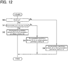
- the travel control process according to the present embodiment will be described below with reference to FIG. 12.
- FIG. 12 is a flowchart illustrating a procedure of setting the presentation prohibition distance Dv in the present embodiment.
- step S40 the overtaking assist function of the control device 19 is used for confirming whether or not the route to the destination is set in the navigation device 15.
- the process proceeds to step S41, in which the overtaking assist function of the control device 19 serves to confirm whether or not the setting of the route traveling assist function is enabled.
- the process proceeds to step S42, in which the overtaking assist function of the control device 19 serves to set the presentation prohibition distance Dv to a first presentation prohibition distance da.
- step S41 When the setting of the route traveling assist function is disabled in step S41, the process proceeds to step S43, in which the overtaking assist function of the control device 19 serves to set the presentation prohibition distance Dv to a second presentation prohibition distance db.
- step S44 the overtaking assist function of the control device 19 serves to set the presentation prohibition distance Dv to a third presentation prohibition distance dc.
- the lane change of the subject vehicle is performed using the route traveling assist function, and therefore the first presentation prohibition distance da is set to be the same as the presentation prohibition distance of the first embodiment thereby to allow the subject vehicle to reliably head to the traveling direction change point.
- the second presentation prohibition distance db is set to be significantly shorter than the first presentation prohibition distance da because the driver performs the steering in accordance with the route guidance provided using the navigation function of the navigation device 15 and therefore even when the overtaking information is presented at a position close to the traveling direction change point, the lane change can be performed with a short distance.
- the third presentation prohibition distance dc is set such that the presentation of the overtaking information is possible even at the traveling direction change point because the route is not set and the route traveling assist function is disabled; therefore, the driver performs the steering of the subject vehicle with his/her own intention and may not necessarily perform the lane change at the traveling direction change point.
- the presentation prohibition distance Dv is set in accordance with whether or not the route is set and/or whether the route traveling assist function is enabled/disabled, but the presentation prohibition distance Dv may be set in accordance with the number of lane changes required to move from the traveling lane of the subject vehicle to the lane including the traveling direction change point. Also in this case, the presentation prohibition distance Dv is preferably set to the above-described second presentation prohibition distance db or more so that the lane change can be safely performed toward the traveling direction change point.
- the travel control apparatus 1 and travel control method for a vehicle of the present embodiments in the case in which the driver is presented with overtaking information as to whether or not to accept execution of an overtaking assist function for the vehicle, which is traveling on a route to a preliminarily set destination, to overtake a preceding vehicle by changing lanes through autonomous travel control, when the distance from the vehicle to a traveling direction change point is shorter than a preliminarily set presentation prohibition distance, the presentation of the overtaking information is not performed; therefore, the presentation prohibition distance is appropriately set and the overtaking information can thereby be prohibited from being presented at the timing when the traveling along the route is hindered.
- the invention as claimed relates to the case in which a navigation function of presenting the route and guiding the driver to the destination and a route traveling assist function of controlling the vehicle to travel along the route by autonomous travel control are provided, when the route traveling assist function is executed, a first presentation prohibition distance is set as the presentation prohibition distance, and when the navigation function is executed, a second presentation prohibition distance shorter than the first presentation prohibition distance is set as the presentation prohibition distance; therefore, in the case in which the driver performs the steering of the vehicle based on the route guidance provided using the navigation function, even when the overtaking information is presented at a position close to the traveling direction change point, the driver's intention can be reflected as much as possible to execute the overtaking assist function.
- the traveling direction change point includes at least one of a branching point, a merging point, an exit from a road, or a tollgate; therefore, even when it is necessary to change lanes at various traveling direction change points in order to travel along the route, it is possible to prevent the occurrence of a situation in which the driver inadvertently accepts the presentation of the overtaking information and cannot head to the traveling direction change points.
Landscapes
- Engineering & Computer Science (AREA)
- Automation & Control Theory (AREA)
- Transportation (AREA)
- Mechanical Engineering (AREA)
- Physics & Mathematics (AREA)
- General Physics & Mathematics (AREA)
- Control Of Driving Devices And Active Controlling Of Vehicle (AREA)
- Traffic Control Systems (AREA)
Claims (4)
- Procédé de commande de déplacement pour un véhicule pour présenter le véhicule se déplaçant sur un itinéraire vers une destination préalablement définie avec des informations de dépassement indiquant s'il faut ou non accepter l'exécution d'une fonction d'assistance au dépassement pour dépasser un véhicule précédent en changeant de voie par le biais d'une commande de déplacement autonome, le procédé de commande de déplacement comprenant :détecter une position du véhicule sur l'itinéraire ; etdétecter s'il existe ou non un point de changement de direction de déplacement sur l'itinéraire devant la position du véhicule, le point de changement de direction de déplacement étant un point auquel le véhicule doit changer sa direction de déplacement,dans lequel, lorsqu'une distance du véhicule au point de changement de direction de déplacement est plus courte que la distance d'interdiction de présentation, la présentation des informations de dépassement n'est pas effectuée,le procédé de commande de déplacement étant caractérisé par :fournir une fonction de navigation permettant de présenter l'itinéraire et de guider le conducteur jusqu'à la destination et une fonction d'assistance au déplacement sur l'itinéraire permettant de commander le véhicule pour qu'il se déplace le long de l'itinéraire par une commande de déplacement autonome ;lorsque la fonction d'assistance au déplacement sur l'itinéraire est exécutée, définir une première distance d'interdiction de présentation comme étant la distance d'interdiction de présentation ; etlorsque la fonction de navigation est exécutée, définir une deuxième distance d'interdiction de présentation plus courte que la première distance d'interdiction de présentation comme étant la distance d'interdiction de présentation.
- Procédé de commande de déplacement pour un véhicule selon la revendication 1, adapté en outre, lorsque ni la fonction de navigation ni la fonction d'assistance au déplacement sur l'itinéraire ne sont exécutées, pour définir une troisième distance d'interdiction de présentation plus courte que la deuxième distance d'interdiction de présentation comme étant la distance d'interdiction de présentation.
- Procédé de commande de déplacement pour un véhicule selon l'une quelconque des revendications 1 et 2, dans lequel le point de changement de direction de déplacement comprend au moins l'un d'un point d'embranchement, d'un point de convergence, d'une sortie de route ou d'un péage.
- Appareil de commande de déplacement pour un véhicule, configuré pour présenter le véhicule se déplaçant sur un itinéraire vers une destination préalablement définie avec des informations de dépassement indiquant s'il faut ou non accepter l'exécution d'une fonction d'assistance au dépassement pour dépasser un véhicule précédent en changeant de voie par le biais d'une commande de déplacement autonome, l'appareil de commande de déplacement fonctionnant pour :détecter une position du véhicule sur l'itinéraire ; etdétecter s'il existe ou non un point de changement de direction de déplacement sur l'itinéraire devant la position du véhicule, le point de changement de direction de déplacement étant un point auquel le véhicule doit changer sa direction de déplacement,dans lequel, lorsqu'une distance du véhicule au point de changement de direction de déplacement est plus courte que la distance d'interdiction de présentation, la présentation des informations de dépassement n'est pas effectuée,l'appareil de commande de déplacement étant caractérisé en ce que l'appareil de commande de déplacement est adapté pour fournir une fonction de navigation permettant de présenter l'itinéraire et de guider le conducteur jusqu'à la destination et une fonction d'assistance au déplacement sur l'itinéraire permettant de commander le véhicule pour qu'il se déplace le long de l'itinéraire par une commande de déplacement autonome ; etlorsque la fonction d'assistance au déplacement sur l'itinéraire est exécutée, pour définir une première distance d'interdiction de présentation comme étant la distance d'interdiction de présentation ; etlorsque la fonction de navigation est exécutée, pour définir une deuxième distance d'interdiction de présentation plus courte que la première distance d'interdiction de présentation comme étant la distance d'interdiction de présentation.
Applications Claiming Priority (1)
| Application Number | Priority Date | Filing Date | Title |
|---|---|---|---|
| PCT/JP2019/019388 WO2020230303A1 (fr) | 2019-05-15 | 2019-05-15 | Procédé de commande de déplacement et dispositif de commande de déplacement pour véhicule |
Publications (3)
| Publication Number | Publication Date |
|---|---|
| EP3971861A1 EP3971861A1 (fr) | 2022-03-23 |
| EP3971861A4 EP3971861A4 (fr) | 2022-06-01 |
| EP3971861B1 true EP3971861B1 (fr) | 2022-12-14 |
Family
ID=73289550
Family Applications (1)
| Application Number | Title | Priority Date | Filing Date |
|---|---|---|---|
| EP19928314.4A Active EP3971861B1 (fr) | 2019-05-15 | 2019-05-15 | Procédé de commande de déplacement et dispositif de commande de déplacement pour véhicule |
Country Status (5)
| Country | Link |
|---|---|
| US (1) | US11447136B2 (fr) |
| EP (1) | EP3971861B1 (fr) |
| JP (1) | JP7143946B2 (fr) |
| CN (1) | CN113811932B (fr) |
| WO (1) | WO2020230303A1 (fr) |
Families Citing this family (9)
| Publication number | Priority date | Publication date | Assignee | Title |
|---|---|---|---|---|
| JP6913716B2 (ja) * | 2019-07-17 | 2021-08-04 | 本田技研工業株式会社 | 車両制御装置、車両制御方法、及びプログラム |
| DE102020204078A1 (de) * | 2019-11-27 | 2021-05-27 | Robert Bosch Gesellschaft mit beschränkter Haftung | Fahrerassistenzsystem für Kraftfahrzeuge |
| JP7347375B2 (ja) * | 2020-08-31 | 2023-09-20 | トヨタ自動車株式会社 | 走行車線計画装置及び走行車線計画用コンピュータプログラム |
| JP7359127B2 (ja) * | 2020-10-20 | 2023-10-11 | トヨタ自動車株式会社 | 自動運転システム |
| WO2023089837A1 (fr) * | 2021-11-22 | 2023-05-25 | 日産自動車株式会社 | Procédé d'aide au déplacement et dispositif d'aide au déplacement pour véhicule |
| CN114252086B (zh) * | 2021-12-22 | 2023-03-03 | 北京百度网讯科技有限公司 | 提示信息的输出方法、装置、设备、介质和车辆 |
| US20230278562A1 (en) * | 2022-03-01 | 2023-09-07 | GM Global Technology Operations LLC | Method to arbitrate multiple automatic lane change requests in proximity to route splits |
| JP7406583B2 (ja) | 2022-03-31 | 2023-12-27 | 本田技研工業株式会社 | 車両システム、制御方法、およびプログラム |
| CN116215534A (zh) * | 2022-12-08 | 2023-06-06 | 深圳曦华科技有限公司 | 超车事件的智能处理方法及相关装置和介质和程序 |
Family Cites Families (34)
| Publication number | Priority date | Publication date | Assignee | Title |
|---|---|---|---|---|
| JP2003063273A (ja) * | 2001-08-30 | 2003-03-05 | Hitachi Ltd | 車両走行制御装置 |
| US7899617B2 (en) * | 2005-02-17 | 2011-03-01 | Denso Corporation | Navigation system providing route guidance in multi-lane road according to vehicle lane position |
| JP4701416B2 (ja) | 2007-01-22 | 2011-06-15 | 独立行政法人土木研究所 | 交通流シミュレーション装置 |
| WO2014097368A1 (fr) * | 2012-12-17 | 2014-06-26 | 三菱電機株式会社 | Dispositif de navigation, dispositif serveur et procédé de guidage d'itinéraire |
| JP6241341B2 (ja) * | 2014-03-20 | 2017-12-06 | アイシン・エィ・ダブリュ株式会社 | 自動運転支援装置、自動運転支援方法及びプログラム |
| JP2015228092A (ja) * | 2014-05-30 | 2015-12-17 | 株式会社デンソー | 運転支援装置および運転支援プログラム |
| JP6103716B2 (ja) * | 2014-06-17 | 2017-03-29 | 富士重工業株式会社 | 車両の走行制御装置 |
| KR101925741B1 (ko) * | 2015-01-13 | 2018-12-05 | 닛산 지도우샤 가부시키가이샤 | 주행 제어 장치 |
| JP2016132421A (ja) * | 2015-01-22 | 2016-07-25 | トヨタ自動車株式会社 | 自動運転装置 |
| JP2016168985A (ja) | 2015-03-16 | 2016-09-23 | トヨタ自動車株式会社 | 走行制御装置 |
| JP6462494B2 (ja) * | 2015-05-29 | 2019-01-30 | 株式会社デンソー | 運転支援装置及び運転支援方法 |
| CA2993635C (fr) * | 2015-07-27 | 2019-08-13 | Nissan Motor Co., Ltd. | Dispositif de guidage routier et procede de guidage routier |
| US20190016338A1 (en) * | 2016-02-18 | 2019-01-17 | Honda Motor Co., Ltd. | Vehicle control device, vehicle control method, and vehicle control program |
| JP6535634B2 (ja) * | 2016-05-26 | 2019-06-26 | 本田技研工業株式会社 | 経路案内装置及び経路案内方法 |
| US9836977B1 (en) * | 2016-06-07 | 2017-12-05 | Delphi Technologies, Inc. | Automated vehicle steering control system with lane position bias |
| JP6460058B2 (ja) * | 2016-07-01 | 2019-01-30 | トヨタ自動車株式会社 | 車両の制御装置 |
| JP6572847B2 (ja) | 2016-08-10 | 2019-09-11 | トヨタ自動車株式会社 | 自動運転システム |
| JP6630267B2 (ja) * | 2016-12-21 | 2020-01-15 | 本田技研工業株式会社 | 車両制御装置 |
| US20210139044A1 (en) | 2017-01-13 | 2021-05-13 | Honda Motor Co., Ltd. | Vehicle control system, vehicle control method, and vehicle control program |
| WO2018138765A1 (fr) * | 2017-01-24 | 2018-08-02 | 本田技研工業株式会社 | Système, procédé et programme de commande de véhicule |
| US20180362084A1 (en) * | 2017-06-19 | 2018-12-20 | Delphi Technologies, Inc. | Automated vehicle lane-keeping system |
| JP6939376B2 (ja) * | 2017-10-10 | 2021-09-22 | トヨタ自動車株式会社 | 自動運転システム |
| WO2019098081A1 (fr) * | 2017-11-20 | 2019-05-23 | ソニー株式会社 | Dispositif de traitement d'informations, procédé de traitement d'informations, programme, et véhicule |
| JP6958385B2 (ja) * | 2018-01-24 | 2021-11-02 | トヨタ自動車株式会社 | 車両制御システム |
| JP7032170B2 (ja) * | 2018-02-23 | 2022-03-08 | 本田技研工業株式会社 | 車両制御装置 |
| US10890449B2 (en) * | 2018-02-26 | 2021-01-12 | Aptiv Technologies Limited | Navigation system |
| JP6916953B2 (ja) * | 2018-03-09 | 2021-08-11 | 本田技研工業株式会社 | 車両制御装置、車両制御方法、およびプログラム |
| JP7030573B2 (ja) * | 2018-03-15 | 2022-03-07 | 本田技研工業株式会社 | 車両制御装置、車両制御方法、およびプログラム |
| JP7117881B2 (ja) * | 2018-04-02 | 2022-08-15 | 本田技研工業株式会社 | 車両制御装置、車両制御方法、およびプログラム |
| JP7048398B2 (ja) * | 2018-04-13 | 2022-04-05 | 本田技研工業株式会社 | 車両制御装置、車両制御方法、およびプログラム |
| US11287814B2 (en) * | 2018-08-07 | 2022-03-29 | GM Global Technology Operations LLC | Lane change detection system and method for an autonomous vehicle |
| JP7004077B2 (ja) * | 2018-08-13 | 2022-01-21 | 日産自動車株式会社 | 車両の走行制御方法及び走行制御装置 |
| JP7147852B2 (ja) * | 2018-08-13 | 2022-10-05 | 日産自動車株式会社 | 車両の走行制御方法及び走行制御装置 |
| KR102592825B1 (ko) * | 2018-08-31 | 2023-10-23 | 현대자동차주식회사 | 충돌 회피 제어 장치 및 그 방법 |
-
2019
- 2019-05-15 JP JP2021519213A patent/JP7143946B2/ja active Active
- 2019-05-15 CN CN201980096220.XA patent/CN113811932B/zh active Active
- 2019-05-15 EP EP19928314.4A patent/EP3971861B1/fr active Active
- 2019-05-15 US US17/609,559 patent/US11447136B2/en active Active
- 2019-05-15 WO PCT/JP2019/019388 patent/WO2020230303A1/fr unknown
Also Published As
| Publication number | Publication date |
|---|---|
| JP7143946B2 (ja) | 2022-09-29 |
| US11447136B2 (en) | 2022-09-20 |
| JPWO2020230303A1 (fr) | 2020-11-19 |
| EP3971861A1 (fr) | 2022-03-23 |
| WO2020230303A1 (fr) | 2020-11-19 |
| EP3971861A4 (fr) | 2022-06-01 |
| CN113811932B (zh) | 2023-01-10 |
| US20220203992A1 (en) | 2022-06-30 |
| CN113811932A (zh) | 2021-12-17 |
Similar Documents
| Publication | Publication Date | Title |
|---|---|---|
| EP3971861B1 (fr) | Procédé de commande de déplacement et dispositif de commande de déplacement pour véhicule | |
| EP3971866B1 (fr) | Procédé et dispositif de commande de déplacement de véhicule | |
| EP3971862B1 (fr) | Procédé de commande de déplacement et dispositif de commande de déplacement pour véhicule | |
| US11505194B2 (en) | Vehicle travel control method and travel control device | |
| US11370433B1 (en) | Vehicle travel control method and vehicle travel control apparatus | |
| EP3971060B1 (fr) | Procédé et dispositif de commande de déplacement de véhicule | |
| US20230356741A1 (en) | Travel Control Method and Travel Control Apparatus for Vehicle | |
| RU2803428C2 (ru) | Способ и устройство управления движением транспортного средства | |
| RU2780639C1 (ru) | Способ управления движением и устройство управления движением для транспортного средства | |
| RU2780638C1 (ru) | Способ управления движением транспортного средства и устройство управления движением | |
| EP4309969A1 (fr) | Procédé de commande de déplacement et dispositif de commande de déplacement pour un véhicule | |
| WO2023089837A1 (fr) | Procédé d'aide au déplacement et dispositif d'aide au déplacement pour véhicule | |
| RU2773993C1 (ru) | Способ управления движением и устройство управления движением для транспортного средства | |
| WO2021106146A1 (fr) | Procédé de commande de déplacement et dispositif de commande de déplacement pour véhicule |
Legal Events
| Date | Code | Title | Description |
|---|---|---|---|
| STAA | Information on the status of an ep patent application or granted ep patent |
Free format text: STATUS: THE INTERNATIONAL PUBLICATION HAS BEEN MADE |
|
| PUAI | Public reference made under article 153(3) epc to a published international application that has entered the european phase |
Free format text: ORIGINAL CODE: 0009012 |
|
| STAA | Information on the status of an ep patent application or granted ep patent |
Free format text: STATUS: REQUEST FOR EXAMINATION WAS MADE |
|
| 17P | Request for examination filed |
Effective date: 20211108 |
|
| AK | Designated contracting states |
Kind code of ref document: A1 Designated state(s): AL AT BE BG CH CY CZ DE DK EE ES FI FR GB GR HR HU IE IS IT LI LT LU LV MC MK MT NL NO PL PT RO RS SE SI SK SM TR |
|
| A4 | Supplementary search report drawn up and despatched |
Effective date: 20220503 |
|
| RIC1 | Information provided on ipc code assigned before grant |
Ipc: G05D 1/00 20060101ALI20220426BHEP Ipc: B60W 50/14 20200101ALI20220426BHEP Ipc: B60W 30/18 20120101ALI20220426BHEP Ipc: G08G 1/0969 20060101ALI20220426BHEP Ipc: G08G 1/00 20060101ALI20220426BHEP Ipc: B60W 30/10 20060101ALI20220426BHEP Ipc: G08G 1/16 20060101AFI20220426BHEP |
|
| DAV | Request for validation of the european patent (deleted) | ||
| DAX | Request for extension of the european patent (deleted) | ||
| GRAP | Despatch of communication of intention to grant a patent |
Free format text: ORIGINAL CODE: EPIDOSNIGR1 |
|
| STAA | Information on the status of an ep patent application or granted ep patent |
Free format text: STATUS: GRANT OF PATENT IS INTENDED |
|
| RIC1 | Information provided on ipc code assigned before grant |
Ipc: G05D 1/00 20060101ALI20220901BHEP Ipc: B60W 50/14 20200101ALI20220901BHEP Ipc: B60W 30/18 20120101ALI20220901BHEP Ipc: G08G 1/0969 20060101ALI20220901BHEP Ipc: G08G 1/00 20060101ALI20220901BHEP Ipc: B60W 30/10 20060101ALI20220901BHEP Ipc: G08G 1/16 20060101AFI20220901BHEP |
|
| INTG | Intention to grant announced |
Effective date: 20220920 |
|
| GRAS | Grant fee paid |
Free format text: ORIGINAL CODE: EPIDOSNIGR3 |
|
| GRAA | (expected) grant |
Free format text: ORIGINAL CODE: 0009210 |
|
| STAA | Information on the status of an ep patent application or granted ep patent |
Free format text: STATUS: THE PATENT HAS BEEN GRANTED |
|
| AK | Designated contracting states |
Kind code of ref document: B1 Designated state(s): AL AT BE BG CH CY CZ DE DK EE ES FI FR GB GR HR HU IE IS IT LI LT LU LV MC MK MT NL NO PL PT RO RS SE SI SK SM TR |
|
| REG | Reference to a national code |
Ref country code: GB Ref legal event code: FG4D |
|
| REG | Reference to a national code |
Ref country code: CH Ref legal event code: EP |
|
| REG | Reference to a national code |
Ref country code: DE Ref legal event code: R096 Ref document number: 602019023280 Country of ref document: DE |
|
| REG | Reference to a national code |
Ref country code: IE Ref legal event code: FG4D |
|
| REG | Reference to a national code |
Ref country code: AT Ref legal event code: REF Ref document number: 1538154 Country of ref document: AT Kind code of ref document: T Effective date: 20230115 |
|
| REG | Reference to a national code |
Ref country code: LT Ref legal event code: MG9D |
|
| REG | Reference to a national code |
Ref country code: NL Ref legal event code: MP Effective date: 20221214 |
|
| PG25 | Lapsed in a contracting state [announced via postgrant information from national office to epo] |
Ref country code: SE Free format text: LAPSE BECAUSE OF FAILURE TO SUBMIT A TRANSLATION OF THE DESCRIPTION OR TO PAY THE FEE WITHIN THE PRESCRIBED TIME-LIMIT Effective date: 20221214 Ref country code: NO Free format text: LAPSE BECAUSE OF FAILURE TO SUBMIT A TRANSLATION OF THE DESCRIPTION OR TO PAY THE FEE WITHIN THE PRESCRIBED TIME-LIMIT Effective date: 20230314 Ref country code: LT Free format text: LAPSE BECAUSE OF FAILURE TO SUBMIT A TRANSLATION OF THE DESCRIPTION OR TO PAY THE FEE WITHIN THE PRESCRIBED TIME-LIMIT Effective date: 20221214 Ref country code: FI Free format text: LAPSE BECAUSE OF FAILURE TO SUBMIT A TRANSLATION OF THE DESCRIPTION OR TO PAY THE FEE WITHIN THE PRESCRIBED TIME-LIMIT Effective date: 20221214 |
|
| REG | Reference to a national code |
Ref country code: AT Ref legal event code: MK05 Ref document number: 1538154 Country of ref document: AT Kind code of ref document: T Effective date: 20221214 |
|
| PG25 | Lapsed in a contracting state [announced via postgrant information from national office to epo] |
Ref country code: RS Free format text: LAPSE BECAUSE OF FAILURE TO SUBMIT A TRANSLATION OF THE DESCRIPTION OR TO PAY THE FEE WITHIN THE PRESCRIBED TIME-LIMIT Effective date: 20221214 Ref country code: LV Free format text: LAPSE BECAUSE OF FAILURE TO SUBMIT A TRANSLATION OF THE DESCRIPTION OR TO PAY THE FEE WITHIN THE PRESCRIBED TIME-LIMIT Effective date: 20221214 Ref country code: HR Free format text: LAPSE BECAUSE OF FAILURE TO SUBMIT A TRANSLATION OF THE DESCRIPTION OR TO PAY THE FEE WITHIN THE PRESCRIBED TIME-LIMIT Effective date: 20221214 Ref country code: GR Free format text: LAPSE BECAUSE OF FAILURE TO SUBMIT A TRANSLATION OF THE DESCRIPTION OR TO PAY THE FEE WITHIN THE PRESCRIBED TIME-LIMIT Effective date: 20230315 |
|
| PG25 | Lapsed in a contracting state [announced via postgrant information from national office to epo] |
Ref country code: NL Free format text: LAPSE BECAUSE OF FAILURE TO SUBMIT A TRANSLATION OF THE DESCRIPTION OR TO PAY THE FEE WITHIN THE PRESCRIBED TIME-LIMIT Effective date: 20221214 |
|
| PG25 | Lapsed in a contracting state [announced via postgrant information from national office to epo] |
Ref country code: SM Free format text: LAPSE BECAUSE OF FAILURE TO SUBMIT A TRANSLATION OF THE DESCRIPTION OR TO PAY THE FEE WITHIN THE PRESCRIBED TIME-LIMIT Effective date: 20221214 Ref country code: RO Free format text: LAPSE BECAUSE OF FAILURE TO SUBMIT A TRANSLATION OF THE DESCRIPTION OR TO PAY THE FEE WITHIN THE PRESCRIBED TIME-LIMIT Effective date: 20221214 Ref country code: PT Free format text: LAPSE BECAUSE OF FAILURE TO SUBMIT A TRANSLATION OF THE DESCRIPTION OR TO PAY THE FEE WITHIN THE PRESCRIBED TIME-LIMIT Effective date: 20230414 Ref country code: ES Free format text: LAPSE BECAUSE OF FAILURE TO SUBMIT A TRANSLATION OF THE DESCRIPTION OR TO PAY THE FEE WITHIN THE PRESCRIBED TIME-LIMIT Effective date: 20221214 Ref country code: EE Free format text: LAPSE BECAUSE OF FAILURE TO SUBMIT A TRANSLATION OF THE DESCRIPTION OR TO PAY THE FEE WITHIN THE PRESCRIBED TIME-LIMIT Effective date: 20221214 Ref country code: CZ Free format text: LAPSE BECAUSE OF FAILURE TO SUBMIT A TRANSLATION OF THE DESCRIPTION OR TO PAY THE FEE WITHIN THE PRESCRIBED TIME-LIMIT Effective date: 20221214 Ref country code: AT Free format text: LAPSE BECAUSE OF FAILURE TO SUBMIT A TRANSLATION OF THE DESCRIPTION OR TO PAY THE FEE WITHIN THE PRESCRIBED TIME-LIMIT Effective date: 20221214 |
|
| PGFP | Annual fee paid to national office [announced via postgrant information from national office to epo] |
Ref country code: FR Payment date: 20230523 Year of fee payment: 5 Ref country code: DE Payment date: 20230526 Year of fee payment: 5 |
|
| PG25 | Lapsed in a contracting state [announced via postgrant information from national office to epo] |
Ref country code: SK Free format text: LAPSE BECAUSE OF FAILURE TO SUBMIT A TRANSLATION OF THE DESCRIPTION OR TO PAY THE FEE WITHIN THE PRESCRIBED TIME-LIMIT Effective date: 20221214 Ref country code: PL Free format text: LAPSE BECAUSE OF FAILURE TO SUBMIT A TRANSLATION OF THE DESCRIPTION OR TO PAY THE FEE WITHIN THE PRESCRIBED TIME-LIMIT Effective date: 20221214 Ref country code: IS Free format text: LAPSE BECAUSE OF FAILURE TO SUBMIT A TRANSLATION OF THE DESCRIPTION OR TO PAY THE FEE WITHIN THE PRESCRIBED TIME-LIMIT Effective date: 20230414 Ref country code: AL Free format text: LAPSE BECAUSE OF FAILURE TO SUBMIT A TRANSLATION OF THE DESCRIPTION OR TO PAY THE FEE WITHIN THE PRESCRIBED TIME-LIMIT Effective date: 20221214 |
|
| REG | Reference to a national code |
Ref country code: DE Ref legal event code: R097 Ref document number: 602019023280 Country of ref document: DE |
|
| PLBE | No opposition filed within time limit |
Free format text: ORIGINAL CODE: 0009261 |
|
| STAA | Information on the status of an ep patent application or granted ep patent |
Free format text: STATUS: NO OPPOSITION FILED WITHIN TIME LIMIT |
|
| PG25 | Lapsed in a contracting state [announced via postgrant information from national office to epo] |
Ref country code: DK Free format text: LAPSE BECAUSE OF FAILURE TO SUBMIT A TRANSLATION OF THE DESCRIPTION OR TO PAY THE FEE WITHIN THE PRESCRIBED TIME-LIMIT Effective date: 20221214 |
|
| PGFP | Annual fee paid to national office [announced via postgrant information from national office to epo] |
Ref country code: GB Payment date: 20230526 Year of fee payment: 5 |
|
| 26N | No opposition filed |
Effective date: 20230915 |
|
| PG25 | Lapsed in a contracting state [announced via postgrant information from national office to epo] |
Ref country code: SI Free format text: LAPSE BECAUSE OF FAILURE TO SUBMIT A TRANSLATION OF THE DESCRIPTION OR TO PAY THE FEE WITHIN THE PRESCRIBED TIME-LIMIT Effective date: 20221214 |
|
| REG | Reference to a national code |
Ref country code: CH Ref legal event code: PL |
|
| PG25 | Lapsed in a contracting state [announced via postgrant information from national office to epo] |
Ref country code: MC Free format text: LAPSE BECAUSE OF FAILURE TO SUBMIT A TRANSLATION OF THE DESCRIPTION OR TO PAY THE FEE WITHIN THE PRESCRIBED TIME-LIMIT Effective date: 20221214 |
|
| REG | Reference to a national code |
Ref country code: BE Ref legal event code: MM Effective date: 20230531 |
|
| PG25 | Lapsed in a contracting state [announced via postgrant information from national office to epo] |
Ref country code: MC Free format text: LAPSE BECAUSE OF FAILURE TO SUBMIT A TRANSLATION OF THE DESCRIPTION OR TO PAY THE FEE WITHIN THE PRESCRIBED TIME-LIMIT Effective date: 20221214 Ref country code: LU Free format text: LAPSE BECAUSE OF NON-PAYMENT OF DUE FEES Effective date: 20230515 Ref country code: LI Free format text: LAPSE BECAUSE OF NON-PAYMENT OF DUE FEES Effective date: 20230531 Ref country code: CH Free format text: LAPSE BECAUSE OF NON-PAYMENT OF DUE FEES Effective date: 20230531 |
|
| REG | Reference to a national code |
Ref country code: IE Ref legal event code: MM4A |
|
| PG25 | Lapsed in a contracting state [announced via postgrant information from national office to epo] |
Ref country code: IE Free format text: LAPSE BECAUSE OF NON-PAYMENT OF DUE FEES Effective date: 20230515 |
|
| PG25 | Lapsed in a contracting state [announced via postgrant information from national office to epo] |
Ref country code: IE Free format text: LAPSE BECAUSE OF NON-PAYMENT OF DUE FEES Effective date: 20230515 |