WO2019098081A1 - Dispositif de traitement d'informations, procédé de traitement d'informations, programme, et véhicule - Google Patents
Dispositif de traitement d'informations, procédé de traitement d'informations, programme, et véhicule Download PDFInfo
- Publication number
- WO2019098081A1 WO2019098081A1 PCT/JP2018/041094 JP2018041094W WO2019098081A1 WO 2019098081 A1 WO2019098081 A1 WO 2019098081A1 JP 2018041094 W JP2018041094 W JP 2018041094W WO 2019098081 A1 WO2019098081 A1 WO 2019098081A1
- Authority
- WO
- WIPO (PCT)
- Prior art keywords
- vehicle
- lane
- unit
- vehicles
- lane change
- Prior art date
Links
Images

Classifications
-
- B—PERFORMING OPERATIONS; TRANSPORTING
- B60—VEHICLES IN GENERAL
- B60W—CONJOINT CONTROL OF VEHICLE SUB-UNITS OF DIFFERENT TYPE OR DIFFERENT FUNCTION; CONTROL SYSTEMS SPECIALLY ADAPTED FOR HYBRID VEHICLES; ROAD VEHICLE DRIVE CONTROL SYSTEMS FOR PURPOSES NOT RELATED TO THE CONTROL OF A PARTICULAR SUB-UNIT
- B60W40/00—Estimation or calculation of non-directly measurable driving parameters for road vehicle drive control systems not related to the control of a particular sub unit, e.g. by using mathematical models
- B60W40/02—Estimation or calculation of non-directly measurable driving parameters for road vehicle drive control systems not related to the control of a particular sub unit, e.g. by using mathematical models related to ambient conditions
- B60W40/04—Traffic conditions
-
- B—PERFORMING OPERATIONS; TRANSPORTING
- B60—VEHICLES IN GENERAL
- B60W—CONJOINT CONTROL OF VEHICLE SUB-UNITS OF DIFFERENT TYPE OR DIFFERENT FUNCTION; CONTROL SYSTEMS SPECIALLY ADAPTED FOR HYBRID VEHICLES; ROAD VEHICLE DRIVE CONTROL SYSTEMS FOR PURPOSES NOT RELATED TO THE CONTROL OF A PARTICULAR SUB-UNIT
- B60W30/00—Purposes of road vehicle drive control systems not related to the control of a particular sub-unit, e.g. of systems using conjoint control of vehicle sub-units, or advanced driver assistance systems for ensuring comfort, stability and safety or drive control systems for propelling or retarding the vehicle
- B60W30/08—Active safety systems predicting or avoiding probable or impending collision or attempting to minimise its consequences
- B60W30/095—Predicting travel path or likelihood of collision
- B60W30/0956—Predicting travel path or likelihood of collision the prediction being responsive to traffic or environmental parameters
-
- G—PHYSICS
- G06—COMPUTING; CALCULATING OR COUNTING
- G06V—IMAGE OR VIDEO RECOGNITION OR UNDERSTANDING
- G06V20/00—Scenes; Scene-specific elements
- G06V20/50—Context or environment of the image
- G06V20/56—Context or environment of the image exterior to a vehicle by using sensors mounted on the vehicle
- G06V20/588—Recognition of the road, e.g. of lane markings; Recognition of the vehicle driving pattern in relation to the road
-
- G—PHYSICS
- G06—COMPUTING; CALCULATING OR COUNTING
- G06V—IMAGE OR VIDEO RECOGNITION OR UNDERSTANDING
- G06V20/00—Scenes; Scene-specific elements
- G06V20/50—Context or environment of the image
- G06V20/59—Context or environment of the image inside of a vehicle, e.g. relating to seat occupancy, driver state or inner lighting conditions
- G06V20/597—Recognising the driver's state or behaviour, e.g. attention or drowsiness
-
- G—PHYSICS
- G08—SIGNALLING
- G08G—TRAFFIC CONTROL SYSTEMS
- G08G1/00—Traffic control systems for road vehicles
- G08G1/01—Detecting movement of traffic to be counted or controlled
- G08G1/0104—Measuring and analyzing of parameters relative to traffic conditions
- G08G1/0108—Measuring and analyzing of parameters relative to traffic conditions based on the source of data
- G08G1/0112—Measuring and analyzing of parameters relative to traffic conditions based on the source of data from the vehicle, e.g. floating car data [FCD]
-
- G—PHYSICS
- G08—SIGNALLING
- G08G—TRAFFIC CONTROL SYSTEMS
- G08G1/00—Traffic control systems for road vehicles
- G08G1/01—Detecting movement of traffic to be counted or controlled
- G08G1/0104—Measuring and analyzing of parameters relative to traffic conditions
- G08G1/0137—Measuring and analyzing of parameters relative to traffic conditions for specific applications
- G08G1/0145—Measuring and analyzing of parameters relative to traffic conditions for specific applications for active traffic flow control
-
- G—PHYSICS
- G08—SIGNALLING
- G08G—TRAFFIC CONTROL SYSTEMS
- G08G1/00—Traffic control systems for road vehicles
- G08G1/16—Anti-collision systems
- G08G1/167—Driving aids for lane monitoring, lane changing, e.g. blind spot detection
-
- B—PERFORMING OPERATIONS; TRANSPORTING
- B60—VEHICLES IN GENERAL
- B60W—CONJOINT CONTROL OF VEHICLE SUB-UNITS OF DIFFERENT TYPE OR DIFFERENT FUNCTION; CONTROL SYSTEMS SPECIALLY ADAPTED FOR HYBRID VEHICLES; ROAD VEHICLE DRIVE CONTROL SYSTEMS FOR PURPOSES NOT RELATED TO THE CONTROL OF A PARTICULAR SUB-UNIT
- B60W30/00—Purposes of road vehicle drive control systems not related to the control of a particular sub-unit, e.g. of systems using conjoint control of vehicle sub-units, or advanced driver assistance systems for ensuring comfort, stability and safety or drive control systems for propelling or retarding the vehicle
- B60W30/08—Active safety systems predicting or avoiding probable or impending collision or attempting to minimise its consequences
- B60W30/095—Predicting travel path or likelihood of collision
- B60W30/0953—Predicting travel path or likelihood of collision the prediction being responsive to vehicle dynamic parameters
Definitions
- the present technology relates to an information processing apparatus, an information processing method, a program, and a vehicle, and more particularly to an information processing apparatus, an information processing method, a program, and a vehicle suitable for use in detecting the flow of a vehicle in an adjacent lane. .
- Patent Document 1 does not consider a method for determining which one of the road lane where the host vehicle is traveling and the adjacent road lane is congested.
- the present technology has been made in view of such a situation, and makes it possible to compare the flow of the vehicle in which the host vehicle is traveling and the flow of vehicles in the adjacent lane.
- the information processing apparatus is a vehicle recognition that is adjacent to a first lane in which the host vehicle is traveling, and performs recognition of a vehicle in a second lane having the same traveling direction as the first lane. And the number of vehicles in the second lane that the host vehicle has caught up on the basis of the recognition result of the vehicles in the second lane, and the number of vehicles in the second lane that the host vehicle has caught up, and Or a flow for detecting a second difference between the number of vehicles in the second lane from which the host vehicle has been overrun and the number of vehicles in the second lane from which the host vehicle has overtaken And a detection unit.
- the information processing apparatus is adjacent to a first lane in which the host vehicle is traveling, and is a vehicle of a second lane having the same traveling direction as the first lane. Based on the recognition result of the vehicle in the second lane, the number of vehicles in the second lane that the vehicle has caught up and the number of vehicles in the second lane that the vehicle caught up are recognized. Or a second difference between the number of vehicles in the second lane from which the host vehicle has been overtaken and the number of vehicles in the second lane from which the host vehicle has overtaken. .
- a program recognizes a vehicle in a second lane adjacent to a first lane in which the host vehicle is traveling and having the same traveling direction as the first lane, and the second A first difference between the number of vehicles in the second lane that the host vehicle has caught up and the number of vehicles in the second lane that the host vehicle has caught, based on the recognition result of the vehicles in the lanes;
- the control unit causes the computer to execute a process of detecting a second difference between the number of vehicles in the second lane from which the host vehicle is overtaken and the number of vehicles in the second lane from which the host vehicle overtakes.
- the vehicle according to the second aspect of the present technology is adjacent to a traveling first lane, and includes a vehicle recognition unit that recognizes a vehicle in a second lane having the same traveling direction as the first lane; A first difference between the number of vehicles in the second lane caught up and the number of vehicles in the second lane caught up based on the recognition result of the vehicles in the second lane, or the first number overtaken A flow detection unit that detects a second difference between the number of vehicles in the second lane and the number of vehicles in the second lane that has been overtaken, and changing the lane according to the first difference or the second difference And an operation control unit for performing control.
- recognition of a vehicle in a second lane adjacent to a first lane in which the host vehicle is traveling and in the same traveling direction as the first lane is performed.
- a second difference between the number of vehicles in the second lane in which the host vehicle has been overtaken and the number of vehicles in the second lane in which the host vehicle has passed is detected.
- recognition of a vehicle in a second lane adjacent to a traveling first lane and traveling in the same direction as the first lane is performed, and the second lane of the second lane is A first difference between the number of vehicles in the second lane caught up and the number of vehicles in the second lane caught up based on the recognition result of the vehicle, or the first one in which the host vehicle is overtaken
- a second difference between the number of vehicles in the second lane and the number of vehicles in the second lane that the host vehicle has overtaken is detected, and the lane change is made according to the first difference or the second difference. It is controlled to do.
- the first aspect or the second aspect of the present technology it is possible to compare the flow of the vehicle in which the host vehicle is traveling with the flow of the vehicle in the adjacent lane. As a result, it is possible to appropriately propose or implement a lane change to the next lane.
- FIG. 1 is a block diagram illustrating an embodiment of a lane change control system to which the present technology is applied. It is a flow chart for explaining lane change control processing. It is a flow chart for explaining lane change control processing. It is a flowchart for demonstrating the detail of a lane change control function automatic setting process. It is a figure for demonstrating the specific example of the count method of a flow comparison counter. It is a figure which shows the example of the judgment method of implementation of a lane change. It is a figure which shows the example of the judgment method of implementation of a lane change. It is a figure showing an example of composition of a computer.
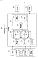
- FIG. 1 is a block diagram showing a configuration example of a schematic function of a vehicle control system 100 which is an example of a mobile control system to which the present technology can be applied.
- the vehicle control system 100 is a system that is provided in the vehicle 10 and performs various controls of the vehicle 10.
- the vehicle 10 is distinguished from other vehicles, it is referred to as the own vehicle or the own vehicle.
- the vehicle control system 100 includes an input unit 101, a data acquisition unit 102, a communication unit 103, an in-vehicle device 104, an output control unit 105, an output unit 106, a drive system control unit 107, a drive system 108, a body system control unit 109, and a body.
- the system system 110, the storage unit 111, and the automatic driving control unit 112 are provided.
- the input unit 101, the data acquisition unit 102, the communication unit 103, the output control unit 105, the drive system control unit 107, the body system control unit 109, the storage unit 111, and the automatic operation control unit 112 are connected via the communication network 121. Connected to each other.
- the communication network 121 may be, for example, an on-vehicle communication network or bus conforming to any standard such as CAN (Controller Area Network), LIN (Local Interconnect Network), LAN (Local Area Network), or FlexRay (registered trademark). Become. In addition, each part of the vehicle control system 100 may be directly connected without passing through the communication network 121.
- CAN Controller Area Network
- LIN Local Interconnect Network
- LAN Local Area Network
- FlexRay registered trademark
- each unit of the vehicle control system 100 performs communication via the communication network 121
- the description of the communication network 121 is omitted.
- the input unit 101 and the automatic driving control unit 112 communicate via the communication network 121, it is described that the input unit 101 and the automatic driving control unit 112 merely communicate.
- the input unit 101 includes an apparatus used by a passenger for inputting various data and instructions.
- the input unit 101 includes operation devices such as a touch panel, a button, a microphone, a switch, and a lever, and an operation device and the like that can be input by a method other than manual operation by voice or gesture.
- the input unit 101 may be a remote control device using infrared rays or other radio waves, or an external connection device such as a mobile device or wearable device corresponding to the operation of the vehicle control system 100.
- the input unit 101 generates an input signal based on data, an instruction, and the like input by the passenger, and supplies the input signal to each unit of the vehicle control system 100.
- the data acquisition unit 102 includes various sensors for acquiring data used for processing of the vehicle control system 100 and supplies the acquired data to each unit of the vehicle control system 100.
- the data acquisition unit 102 includes various sensors for detecting the state of the vehicle 10 and the like.
- the data acquisition unit 102 includes a gyro sensor, an acceleration sensor, an inertia measurement device (IMU), an operation amount of an accelerator pedal, an operation amount of a brake pedal, a steering angle of a steering wheel, and an engine speed.
- IMU inertia measurement device
- a sensor or the like for detecting a motor rotation speed or a rotation speed of a wheel is provided.
- the data acquisition unit 102 includes various sensors for detecting information outside the vehicle 10.
- the data acquisition unit 102 includes an imaging device such as a ToF (Time Of Flight) camera, a stereo camera, a monocular camera, an infrared camera, and other cameras.
- the data acquisition unit 102 includes an environment sensor for detecting weather, weather, etc., and an ambient information detection sensor for detecting an object around the vehicle 10.
- the environment sensor includes, for example, a raindrop sensor, a fog sensor, a sunshine sensor, a snow sensor, and the like.
- the ambient information detection sensor is made of, for example, an ultrasonic sensor, a radar, LiDAR (Light Detection and Ranging, Laser Imaging Detection and Ranging), sonar or the like.
- the data acquisition unit 102 includes various sensors for detecting the current position of the vehicle 10.
- the data acquisition unit 102 includes a GNSS receiver or the like which receives a GNSS signal from a Global Navigation Satellite System (GNSS) satellite.
- GNSS Global Navigation Satellite System
- the data acquisition unit 102 includes various sensors for detecting information in the vehicle.
- the data acquisition unit 102 includes an imaging device for imaging a driver, a biological sensor for detecting biological information of the driver, a microphone for collecting sound in a vehicle interior, and the like.
- the biological sensor is provided, for example, on a seat or a steering wheel, and detects biological information of an occupant sitting on a seat or a driver holding the steering wheel.
- the communication unit 103 communicates with the in-vehicle device 104 and various devices outside the vehicle, a server, a base station, etc., and transmits data supplied from each portion of the vehicle control system 100, and receives the received data. Supply to each part of 100.
- the communication protocol supported by the communication unit 103 is not particularly limited, and the communication unit 103 can also support a plurality of types of communication protocols.
- the communication unit 103 performs wireless communication with the in-vehicle device 104 by wireless LAN, Bluetooth (registered trademark), NFC (Near Field Communication), WUSB (Wireless USB), or the like. Also, for example, the communication unit 103 may use a Universal Serial Bus (USB), a High-Definition Multimedia Interface (HDMI (registered trademark)), or an MHL (Universal Serial Bus) via a connection terminal (and a cable, if necessary) not shown. Wired communication is performed with the in-vehicle device 104 by Mobile High-definition Link) or the like.
- USB Universal Serial Bus
- HDMI High-Definition Multimedia Interface
- MHL Universal Serial Bus
- the communication unit 103 may communicate with an apparatus (for example, an application server or control server) existing on an external network (for example, the Internet, a cloud network, or a network unique to an operator) via a base station or an access point. Communicate. Also, for example, the communication unit 103 may use a P2P (Peer To Peer) technology to connect with a terminal (for example, a pedestrian or a shop terminal, or a MTC (Machine Type Communication) terminal) existing in the vicinity of the vehicle 10. Communicate. Further, for example, the communication unit 103 may perform vehicle to vehicle communication, vehicle to infrastructure communication, communication between the vehicle 10 and a house, and communication between the vehicle 10 and the pedestrian. ) V2X communication such as communication is performed. Also, for example, the communication unit 103 includes a beacon receiving unit, receives radio waves or electromagnetic waves transmitted from radio stations installed on roads, and acquires information such as current position, traffic jam, traffic restriction, or required time. Do.
- an apparatus for example, an application server or control server
- the in-vehicle device 104 includes, for example, a mobile device or wearable device of a passenger, an information device carried in or attached to the vehicle 10, a navigation device for searching for a route to an arbitrary destination, and the like.
- the output control unit 105 controls the output of various information to the occupant of the vehicle 10 or the outside of the vehicle.
- the output control unit 105 generates an output signal including at least one of visual information (for example, image data) and auditory information (for example, audio data), and supplies the generated output signal to the output unit 106.
- the output control unit 105 combines image data captured by different imaging devices of the data acquisition unit 102 to generate an overhead image or a panoramic image, and an output signal including the generated image is generated.
- the output unit 106 is supplied.
- the output control unit 105 generates voice data including a warning sound or a warning message for danger such as collision, contact, entering a danger zone, and the like, and outputs an output signal including the generated voice data to the output unit 106.
- Supply for example, the output control unit 105 generates voice data including a warning sound or a warning message for danger such as collision, contact, entering a danger zone, and the like, and outputs an
- the output unit 106 includes a device capable of outputting visual information or auditory information to an occupant of the vehicle 10 or the outside of the vehicle.
- the output unit 106 includes a display device, an instrument panel, an audio speaker, headphones, wearable devices such as a glasses-type display worn by a passenger, a projector, a lamp, and the like.
- the display device included in the output unit 106 has visual information in the driver's field of vision, such as a head-up display, a transmissive display, and a device having an AR (Augmented Reality) display function, in addition to a device having a normal display. It may be an apparatus for displaying.
- the drive system control unit 107 controls the drive system 108 by generating various control signals and supplying them to the drive system 108. In addition, the drive system control unit 107 supplies a control signal to each unit other than the drive system 108 as necessary, and notifies a control state of the drive system 108, and the like.
- the driveline system 108 includes various devices related to the driveline of the vehicle 10.
- the drive system 108 includes a driving force generating device for generating a driving force of an internal combustion engine or a driving motor, a driving force transmission mechanism for transmitting the driving force to the wheels, and a steering mechanism for adjusting a steering angle.
- a braking system that generates a braking force an antilock brake system (ABS), an electronic stability control (ESC), an electric power steering apparatus, and the like are provided.
- the body control unit 109 controls the body system 110 by generating various control signals and supplying the control signals to the body system 110.
- the body system control unit 109 supplies a control signal to each unit other than the body system 110, as required, to notify the control state of the body system 110, and the like.
- the body system 110 includes various devices of the body system mounted on the vehicle body.
- the body system 110 includes a keyless entry system, a smart key system, a power window device, a power seat, a steering wheel, an air conditioner, and various lamps (for example, headlamps, back lamps, brake lamps, blinkers, fog lamps, etc.) Etc.
- the storage unit 111 includes, for example, a read only memory (ROM), a random access memory (RAM), a magnetic storage device such as a hard disk drive (HDD), a semiconductor storage device, an optical storage device, and a magneto-optical storage device. .
- the storage unit 111 stores various programs, data, and the like used by each unit of the vehicle control system 100.
- the storage unit 111 is map data such as a three-dimensional high-accuracy map such as a dynamic map, a global map that has a lower accuracy than a high-accuracy map and covers a wide area, and information around the vehicle 10 Remember.
- the autonomous driving control unit 112 performs control regarding autonomous driving such as autonomous traveling or driving assistance. Specifically, for example, the automatic driving control unit 112 can avoid collision or reduce the impact of the vehicle 10, follow-up traveling based on the inter-vehicle distance, vehicle speed maintenance traveling, collision warning of the vehicle 10, lane departure warning of the vehicle 10, etc. Coordinated control is carried out to realize the functions of the Advanced Driver Assistance System (ADAS), including: Further, for example, the automatic driving control unit 112 performs cooperative control for the purpose of automatic driving or the like that travels autonomously without depending on the driver's operation.
- the automatic driving control unit 112 includes a detection unit 131, a self position estimation unit 132, a situation analysis unit 133, a planning unit 134, and an operation control unit 135.
- the detection unit 131 detects various types of information necessary for control of automatic driving.
- the detection unit 131 includes an out-of-vehicle information detection unit 141, an in-vehicle information detection unit 142, and a vehicle state detection unit 143.
- the outside-of-vehicle information detection unit 141 performs detection processing of information outside the vehicle 10 based on data or signals from each unit of the vehicle control system 100. For example, the outside information detection unit 141 performs detection processing of an object around the vehicle 10, recognition processing, tracking processing, and detection processing of the distance to the object.
- the objects to be detected include, for example, vehicles, people, obstacles, structures, roads, traffic lights, traffic signs, road markings and the like. Further, for example, the outside-of-vehicle information detection unit 141 performs a process of detecting the environment around the vehicle 10.
- the surrounding environment to be detected includes, for example, weather, temperature, humidity, brightness, road surface condition and the like.
- the information outside the vehicle detection unit 141 indicates data indicating the result of the detection process as the self position estimation unit 132, the map analysis unit 151 of the situation analysis unit 133, the traffic rule recognition unit 152, the situation recognition unit 153, and the operation control unit 135. Supply to the emergency situation avoidance unit 171 and the like.
- the in-vehicle information detection unit 142 performs in-vehicle information detection processing based on data or signals from each unit of the vehicle control system 100.
- the in-vehicle information detection unit 142 performs a driver authentication process and recognition process, a driver state detection process, a passenger detection process, an in-vehicle environment detection process, and the like.
- the state of the driver to be detected includes, for example, physical condition, awakening degree, concentration degree, fatigue degree, gaze direction and the like.
- the in-vehicle environment to be detected includes, for example, temperature, humidity, brightness, smell and the like.
- the in-vehicle information detection unit 142 supplies data indicating the result of the detection process to the situation recognition unit 153 of the situation analysis unit 133, the emergency situation avoidance unit 171 of the operation control unit 135, and the like.
- the vehicle state detection unit 143 detects the state of the vehicle 10 based on data or signals from each unit of the vehicle control system 100.
- the state of the vehicle 10 to be detected includes, for example, speed, acceleration, steering angle, presence / absence of abnormality and contents, state of driving operation, position and inclination of power seat, state of door lock, and other on-vehicle devices. Status etc. are included.
- the vehicle state detection unit 143 supplies data indicating the result of the detection process to the situation recognition unit 153 of the situation analysis unit 133, the emergency situation avoidance unit 171 of the operation control unit 135, and the like.
- Self position estimation unit 132 estimates the position and orientation of vehicle 10 based on data or signals from each part of vehicle control system 100 such as external information detection unit 141 and situation recognition unit 153 of situation analysis unit 133. Do the processing. In addition, the self position estimation unit 132 generates a local map (hereinafter, referred to as a self position estimation map) used to estimate the self position, as necessary.
- the self-location estimation map is, for example, a high-accuracy map using a technique such as SLAM (Simultaneous Localization and Mapping).
- the self position estimation unit 132 supplies data indicating the result of the estimation process to the map analysis unit 151, the traffic rule recognition unit 152, the situation recognition unit 153, and the like of the situation analysis unit 133.
- the self position estimation unit 132 stores the self position estimation map in the storage unit 111.
- the situation analysis unit 133 analyzes the situation of the vehicle 10 and the surroundings.
- the situation analysis unit 133 includes a map analysis unit 151, a traffic rule recognition unit 152, a situation recognition unit 153, and a situation prediction unit 154.
- the map analysis unit 151 uses various data or signals stored in the storage unit 111 while using data or signals from each part of the vehicle control system 100 such as the self position estimation unit 132 and the external information detection unit 141 as necessary. Perform analysis processing and construct a map that contains information necessary for automatic driving processing.
- the map analysis unit 151 is configured of the traffic rule recognition unit 152, the situation recognition unit 153, the situation prediction unit 154, the route planning unit 161 of the planning unit 134, the action planning unit 162, the operation planning unit 163, and the like. Supply to
- the traffic rule recognition unit 152 uses traffic rules around the vehicle 10 based on data or signals from each unit of the vehicle control system 100 such as the self position estimation unit 132, the outside information detection unit 141, and the map analysis unit 151. Perform recognition processing. By this recognition process, for example, the position and state of signals around the vehicle 10, the contents of traffic restrictions around the vehicle 10, and the travelable lanes and the like are recognized.
- the traffic rule recognition unit 152 supplies data indicating the result of the recognition process to the situation prediction unit 154 and the like.
- the situation recognition unit 153 uses data or signals from each unit of the vehicle control system 100 such as the self position estimation unit 132, the outside information detection unit 141, the in-vehicle information detection unit 142, the vehicle state detection unit 143, and the map analysis unit 151. Based on the recognition processing of the situation regarding the vehicle 10 is performed. For example, the situation recognition unit 153 performs recognition processing of the situation of the vehicle 10, the situation around the vehicle 10, the situation of the driver of the vehicle 10, and the like. In addition, the situation recognition unit 153 generates a local map (hereinafter referred to as a situation recognition map) used to recognize the situation around the vehicle 10 as needed.
- the situation recognition map is, for example, an Occupancy Grid Map.
- the situation of the vehicle 10 to be recognized includes, for example, the position, attitude, movement (for example, speed, acceleration, moving direction, etc.) of the vehicle 10, and the presence or absence and contents of abnormality.
- the circumstances around the vehicle 10 to be recognized include, for example, the type and position of surrounding stationary objects, the type, position and movement of surrounding animals (eg, speed, acceleration, movement direction, etc.) Configuration and road surface conditions, as well as ambient weather, temperature, humidity, brightness, etc. are included.
- the state of the driver to be recognized includes, for example, physical condition, alertness level, concentration level, fatigue level, movement of eyes, driving operation and the like.
- the situation recognition unit 153 supplies data (including a situation recognition map, if necessary) indicating the result of the recognition process to the self position estimation unit 132, the situation prediction unit 154, and the like. In addition, the situation recognition unit 153 stores the situation recognition map in the storage unit 111.
- the situation prediction unit 154 performs a prediction process of the situation regarding the vehicle 10 based on data or signals from each part of the vehicle control system 100 such as the map analysis unit 151, the traffic rule recognition unit 152, and the situation recognition unit 153. For example, the situation prediction unit 154 performs prediction processing of the situation of the vehicle 10, the situation around the vehicle 10, the situation of the driver, and the like.
- the situation of the vehicle 10 to be predicted includes, for example, the behavior of the vehicle 10, the occurrence of an abnormality, the travelable distance, and the like.
- the situation around the vehicle 10 to be predicted includes, for example, the behavior of the moving object around the vehicle 10, the change of the signal state, and the change of the environment such as the weather.
- the driver's condition to be predicted includes, for example, the driver's behavior and physical condition.
- the situation prediction unit 154 together with data from the traffic rule recognition unit 152 and the situation recognition unit 153, indicates data indicating the result of the prediction process, the route planning unit 161 of the planning unit 134, the action planning unit 162, and the operation planning unit 163. Supply to etc.
- the route planning unit 161 plans a route to a destination based on data or signals from each unit of the vehicle control system 100 such as the map analysis unit 151 and the situation prediction unit 154. For example, the route planning unit 161 sets a route from the current position to the specified destination based on the global map. In addition, for example, the route planning unit 161 changes the route as appropriate based on traffic jams, accidents, traffic restrictions, conditions such as construction, the physical condition of the driver, and the like. The route planning unit 161 supplies data indicating the planned route to the action planning unit 162 and the like.
- the action planning part 162 Based on data or signals from each part of the vehicle control system 100 such as the map analyzing part 151 and the situation predicting part 154, the action planning part 162 safely makes the route planned by the route planning part 161 within the planned time. Plan the action of the vehicle 10 to travel.
- the action planning unit 162 performs planning of start, stop, traveling direction (for example, forward, backward, left turn, right turn, change of direction, etc.), traveling lane, traveling speed, overtaking, and the like.
- the action plan unit 162 supplies data indicating the planned action of the vehicle 10 to the operation plan unit 163 and the like.
- the operation planning unit 163 is an operation of the vehicle 10 for realizing the action planned by the action planning unit 162 based on data or signals from each unit of the vehicle control system 100 such as the map analysis unit 151 and the situation prediction unit 154. Plan.
- the operation plan unit 163 plans acceleration, deceleration, a traveling track, and the like.
- the operation planning unit 163 supplies data indicating the planned operation of the vehicle 10 to the acceleration / deceleration control unit 172, the direction control unit 173, and the like of the operation control unit 135.
- the operation control unit 135 controls the operation of the vehicle 10.
- the operation control unit 135 includes an emergency situation avoidance unit 171, an acceleration / deceleration control unit 172, and a direction control unit 173.
- the emergency situation avoidance unit 171 is based on the detection results of the external information detection unit 141, the in-vehicle information detection unit 142, and the vehicle state detection unit 143, collision, contact, entry into a danger zone, driver abnormality, vehicle 10 Perform detection processing of an emergency such as When the emergency situation avoidance unit 171 detects the occurrence of an emergency situation, it plans the operation of the vehicle 10 for avoiding an emergency situation such as a sudden stop or a sharp turn.
- the emergency situation avoidance unit 171 supplies data indicating the planned operation of the vehicle 10 to the acceleration / deceleration control unit 172, the direction control unit 173, and the like.
- the acceleration / deceleration control unit 172 performs acceleration / deceleration control for realizing the operation of the vehicle 10 planned by the operation planning unit 163 or the emergency situation avoidance unit 171.
- the acceleration / deceleration control unit 172 calculates a control target value of a driving force generator or a braking device for achieving planned acceleration, deceleration, or sudden stop, and drives a control command indicating the calculated control target value. It is supplied to the system control unit 107.
- the direction control unit 173 performs direction control for realizing the operation of the vehicle 10 planned by the operation planning unit 163 or the emergency situation avoidance unit 171. For example, the direction control unit 173 calculates the control target value of the steering mechanism for realizing the traveling track or the sharp turn planned by the operation plan unit 163 or the emergency situation avoidance unit 171, and performs control indicating the calculated control target value. The command is supplied to the drive system control unit 107.
- the data acquisition unit 102, the output control unit 105, the output unit 106, the self position estimation unit 132, the situation analysis unit 133, and the operation control unit 135 are mainly included in the vehicle control system 100 of FIG. It relates to the processing of the action plan unit 162 and the operation plan unit 163.
- FIG. 2 is a block diagram showing a configuration example of a lane change control system 200 according to an embodiment of the present technology.
- Lane change control system 200 is adjacent to a lane on which vehicle 10 on which lane change control system 200 is provided is traveling (hereinafter referred to as a traveling lane) and a traveling lane, and the traveling lane and traveling direction are This is a system that detects a difference in vehicle flow with the same lane (hereinafter referred to as an adjacent lane), and proposes lane control or controls based on the result.
- the lane change control system 200 includes an input unit 201, a data acquisition unit 202, an information processing unit 203, a presentation unit 204, and a storage unit 205.
- the input unit 201 includes, for example, operation devices such as a touch panel, a button, a microphone, a switch, and a lever, and an operation device or the like that can be input by a method other than a manual operation by voice or gesture.
- the input unit 201 generates an input signal based on data, an instruction, and the like input by a passenger of the vehicle 10, and supplies the input signal to the information processing unit 203.
- the data acquisition unit 202 includes an imaging unit 211, a sensor unit 212, and a GNSS receiver 213.
- the imaging unit 211 includes one or more cameras, and, for example, performs imaging of the surroundings such as the front, the side, and the rear of the vehicle 10.
- the imaging unit 211 supplies the image obtained as a result of imaging to the information processing unit 203.
- the sensor unit 212 includes various sensors for detecting the state of the vehicle 10 and the like.
- the sensor unit 212 may be a gyro sensor, an acceleration sensor, an inertia measurement device (IMU), an operation amount of an accelerator pedal, an operation amount of a brake pedal, a steering angle of a steering wheel, an engine rotation number, a motor rotation number, or A sensor or the like for detecting a rotational speed or the like of a wheel is provided.
- the sensor unit 212 also includes various sensors for detecting information outside the vehicle 10.
- the sensor unit 212 includes an ambient information detection sensor for detecting an object around the vehicle 10.
- the ambient information detection sensor is, for example, an ultrasonic sensor, a radar, a LiDAR, a sonar or the like.
- the sensor unit 212 supplies sensor data indicating the detection result of each sensor to the information processing unit 203.
- the GNSS receiver 213 receives a GNSS signal transmitted from a positioning satellite (not shown) of the GNSS, and supplies the received GNSS signal to the information processing unit 203.
- the information processing unit 203 includes a self position estimation unit 221, a vehicle state detection unit 222, a vehicle recognition unit 223, a situation analysis unit 224, a threshold setting unit 225, a flow detection unit 226, and a lane change processing unit 227.
- the self position estimation unit 221 performs self position estimation of the vehicle 10 based on the GNSS signal received by the GNSS receiver 213, and estimates the current position and attitude of the vehicle.
- the self position estimation unit 221 supplies data indicating the estimation result to the situation analysis unit 224 and the threshold setting unit 225.
- the vehicle state detection unit 222 detects the state of the vehicle 10 based on the sensor data from the sensor unit 212.
- the state of the vehicle 10 to be detected includes, for example, the speed, the acceleration, the steering angle, the presence or absence of abnormality, the content, the state of the driving operation, and the like.
- the vehicle state detection unit 222 supplies data indicating the detection result to the situation analysis unit 224, the flow detection unit 226, and the lane change determination unit 231 of the lane change processing unit 227.
- the vehicle recognition unit 223 performs recognition processing of a vehicle in an adjacent lane based on an image captured by the imaging unit 211, sensor data from the sensor unit 212, and the like.
- the vehicle recognition unit 223 supplies data indicating the recognition result to the flow detection unit 226.
- the vehicle recognition unit 223 generates and updates the adjacent vehicle information indicating the characteristic of the vehicle in the recognized adjacent lane, and stores the adjacent vehicle information in the storage unit 205.
- the adjacent vehicle information is used to distinguish vehicles in adjacent lanes traveling next to the vehicle 10, and includes, for example, vehicle type, color, shape, vehicle number, number of passengers, characteristics of passengers, and the like.
- the situation analysis unit 224 is an image around the vehicle 10, sensor data from the sensor unit 212, a GNSS signal, an estimation result of the vehicle's 10 own position, a state of the vehicle 10, and map data stored in the storage unit 205.
- the analysis processing of the situation around the vehicle 10 and the vehicle is performed based on the like.
- the situation analysis unit 224 analyzes the characteristics, changes, and speed limit of the road while traveling, the distance between vehicles, the situation of the traveling direction of the vehicle 10, the presence or absence of lane change, and the like.
- the situation analysis unit 224 supplies data indicating the analysis result to the threshold value setting unit 225, the flow detection unit 226, and the lane change determination unit 231 of the lane change processing unit 227.
- the threshold setting unit 225 sets a lane change threshold used to determine a lane change. For example, when automatic setting of the lane change threshold is enabled, the threshold setting unit 225 determines the lane change threshold based on the road on which the vehicle 10 is traveling and the lane change history stored in the storage unit 205. Set On the other hand, when the automatic setting of the lane change threshold is invalidated, the threshold setting unit 225 sets, for example, the lane change threshold to a prescribed value. The threshold setting unit 225 supplies data indicating the set lane change threshold to the lane change determination unit 231.
- the automatic setting of the lane change threshold is set, for example, to be valid or invalid by the operation of the passenger via the input unit 201.
- the lane change history is a record of a history of lane changes made by the driver's operation in the past.
- the lane change history includes, for example, the date and time of the lane change, the road on which the lane was changed, and the value of the flow comparison counter at the time of the lane change.
- the division of the road for specifying the road which performed the lane change can be set arbitrarily.
- the flow comparison counter is a counter that indicates the result of comparing the flow of the vehicle in the traveling lane and the vehicle in the adjacent lane.
- the flow comparison counter is represented by a difference value between the number of vehicles in the adjacent lane which the vehicle 10 has caught up and the number of vehicles in the adjacent lane which the vehicle 10 has caught up on the basis of a predetermined timing.
- the flow comparison counter is incremented by one when the vehicle 10 is overtaken by the vehicle in the adjacent lane, and is decremented by one when the vehicle 10 catches by the vehicle in the adjacent lane.
- the flow comparison counter has a positive value.
- the number of vehicles in the adjacent lane that the vehicle 10 has caught up is greater than the number of vehicles in the adjacent lane that the vehicle 10 has caught up, that is, if the flow of vehicles is better in the running lane than in the adjacent lane
- the comparison counter has a negative value.
- the predetermined timing is, for example, when the vehicle 10 enters or joins a new road, or changes lanes.
- the flow detection unit 226 detects the difference between the flow of vehicles in the traveling lane and the adjacent lane by updating the flow comparison counter based on the speed of the vehicle 10 and the recognition result of the vehicle in the adjacent lane.
- the flow detection unit 226 supplies data indicating the value of the flow comparison counter to the lane change determination unit 231.
- the lane change processing unit 227 performs lane change processing related to the lane change of the vehicle 10.
- the lane change processing unit 227 includes a lane change determination unit 231, a presentation control unit 232, and an operation control unit 233.
- the lane change determination unit 231 determines whether it is better to change the adjacent lane based on the situation in the traveling direction of the vehicle 10, the lane change threshold, and the flow comparison counter.
- the lane change determination unit 231 instructs the presentation control unit 232 to propose a lane change or instructs the operation control unit 233 to perform a lane change when it is determined that the lane change to the adjacent lane is preferable. .
- the lane change determination unit 231 generates and updates a lane change history.
- the lane change determination unit 231 is based on the distance between the vehicle to the previous vehicle, the speed limit of the running road, and the speed of the vehicle 10. Setting of the lane change control function.
- the automatic setting of the lane change control function is set to be valid or invalid, for example, by the operation of the passenger via the input unit 201.
- the presentation control unit 232 controls the presentation unit 204 to propose the driver to change lanes to an adjacent lane.
- the operation control unit 233 controls, for example, the drive system control unit 107 of the vehicle 10 in FIG. 1 to change the lane of the vehicle 10.
- the presentation unit 204 includes a device that presents information by an image such as a display, a speaker, a lighting device, and a vibrator, sound, light, vibration, and the like.
- the storage unit 205 stores map data, a lane change history, and the like.
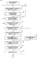
- lane change control processing executed by the lane change control system 200 will be described with reference to the flowcharts of FIGS. 3 and 4.
- This process is started, for example, when an operation for starting the vehicle 10 and starting driving is performed, for example, when an ignition switch, a power switch, or a start switch of the vehicle 10 is turned on. Ru. Further, this process ends, for example, when an operation for ending the driving is performed, for example, when an ignition switch, a power switch, a start switch or the like of the vehicle 10 is turned off.
- step S1 the lane change determination unit 231 determines whether or not the automatic setting of the lane change control function is enabled. When it is determined that the automatic setting of the lane change control function is enabled, the process proceeds to step S2.
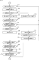
- step S2 the information processing unit 203 executes lane change control function automatic setting processing, and the processing proceeds to step S3.
- step S51 the situation analysis unit 224 detects an inter-vehicle distance. For example, based on at least one of the image in front of the vehicle 10 taken by the imaging unit 211 and the sensor data from the sensor unit 212, the situation analysis unit 224 selects one of the traveling lanes by a predetermined method. Perform detection processing of the last vehicle. Then, the situation analysis unit 224 detects the inter-vehicle distance between the detected vehicle and the vehicle 10. The situation analysis unit 224 supplies data indicating the detected inter-vehicle distance to the lane change determination unit 231.
- the method of detecting the vehicle ahead and the distance between vehicles is not particularly limited.
- step S52 the lane change determination unit 231 determines whether the inter-vehicle distance is sufficient. For example, when the inter-vehicle distance is less than the predetermined threshold value, the lane change determination unit 231 determines that the inter-vehicle distance is not sufficient, and the process proceeds to step S53.
- step S53 the situation analysis unit 224 acquires speed limit information. Specifically, the self-position estimation unit 221 estimates the current position of the vehicle 10 based on the GNSS signal received by the GNSS receiver 213. The self position estimation unit 221 supplies data indicating the current position of the vehicle 10 to the situation analysis unit 224. The situation analysis unit 224 acquires speed limit information of the road on which the vehicle 10 is traveling, based on the current position of the vehicle 10 and the map data stored in the storage unit 205. The situation analysis unit 224 supplies the acquired speed limit information to the lane change determination unit 231.
- step S54 the vehicle state detection unit 222 detects the vehicle speed based on the sensor data from the sensor unit 212.
- the vehicle state detection unit 222 supplies data indicating the detected vehicle speed to the lane change determination unit 231.
- step S55 the lane change determination unit 231 determines whether the vehicle is traveling at a low speed. For example, the lane change determination unit 231 determines that the vehicle 10 is traveling at a low speed when (speed limit-vehicle speed) ⁇ predetermined threshold value, that is, when the vehicle speed is considerably slower than the speed limit. The process proceeds to step S56.
- step S56 the lane change determination unit 231 determines whether the lane change control function is disabled. If it is determined that the lane change control function is disabled, the process proceeds to step S57.
- step S57 the lane change determination unit 231 enables the lane change control function.
- the lane change control function is automatically enabled. Then, updating of the flow comparison counter by the flow detection unit 226 described later, lane change processing by the lane change processing unit 227, and the like are started.
- step S56 when it is determined in step S56 that the lane change control function is enabled, the process of step S57 is skipped, and the lane change control function automatic setting process ends.
- step S55 the lane change determination unit 231 determines that the vehicle is traveling at or near the speed limit if (speed limit-vehicle speed) ⁇ predetermined threshold value, that is, if the vehicle 10 is traveling at or near the speed limit. It is determined that the vehicle 10 is not traveling at a low speed, and the process proceeds to step S58.
- step S52 when it is determined that the inter-vehicle distance is sufficient, the process proceeds to step S58.
- step S58 the lane change determination unit 231 determines whether the lane change control function is enabled. If it is determined that the lane change control function is enabled, the process proceeds to step S59.
- step S59 the lane change determination unit 231 invalidates the lane change control function.
- the lane change control function is automatically invalidated. Then, updating of the flow comparison counter by the flow detection unit 226 described later, lane change processing by the lane change processing unit 227, and the like are stopped.
- step S58 determines that the lane change control function has been invalidated. If it is determined in step S58 that the lane change control function has been invalidated, the process of step S59 is skipped, and the lane change control function automatic setting process ends.
- step S1 when it is determined in step S1 that the automatic setting of the lane change control function is invalidated, the process of step S2 is skipped, and the process proceeds to step S3.
- step S3 the lane change determination unit 231 determines whether the lane change control function is enabled. If it is determined that the lane change control function is disabled, the process returns to step S1.
- step S3 the processes of steps S1 to S3 are repeatedly executed until it is determined that the lane change control function is enabled.
- step S3 when it is determined in step S3 that the lane change control function is enabled, the process proceeds to step S4.
- step S4 This is, for example, when the lane change control function is activated in advance, when the lane change control function is automatically activated, or when the lane change control function is activated by the operation of the driver or the like. is there.
- step S4 the situation analysis unit 224 determines whether the number of lanes in the traveling direction of the host vehicle (vehicle 10) is plural.
- the self-position estimation unit 221 estimates the current position of the vehicle 10 based on the GNSS signal received by the GNSS receiver 213.
- the self position estimation unit 221 supplies data indicating the current position of the vehicle 10 to the situation analysis unit 224.
- the situation analysis unit 224 recognizes the road on which the vehicle 10 is traveling, based on the current position of the vehicle 10 and the map data stored in the storage unit 205. Then, when the situation analysis unit 224 determines that there is only one lane in the traveling direction of the vehicle 10 on the recognized road, the process returns to step S1.
- steps S1 to S4 are repeatedly performed until it is determined in step S4 that there are a plurality of lanes in the traveling direction of the vehicle 10.
- step S4 when it is determined in step S4 that there are a plurality of lanes in the traveling direction of the vehicle 10, the process proceeds to step S5.
- the determination method of whether the lane of the advancing direction of the vehicle 10 is multiple is not limited to the method mentioned above.
- the situation analysis unit 224 may perform the determination process based on the image captured by the imaging unit 211.
- step S5 the threshold setting unit 225 determines whether or not automatic setting of the lane change threshold is enabled. If it is determined that the automatic setting of the lane change threshold is enabled, the process proceeds to step S6.
- step S6 the threshold setting unit 225 determines whether the lane change history of the road on which the vehicle is traveling is recorded. Specifically, the situation analysis unit 224 supplies the threshold setting unit 225 with data indicating the recognition result of the road on which the vehicle 10 is traveling. When the lane change history stored in the storage unit 205 includes a history of the road in which the vehicle is traveling, the threshold setting unit 225 determines that the lane change history of the road in which the vehicle is traveling is recorded. The process proceeds to step S7.
- the threshold setting unit 225 sets a lane change threshold based on the lane change history. For example, the threshold setting unit 225 calculates the average value of the flow comparison counters at the time of the lane change in the past recorded in the lane change history of the road on which the vehicle is traveling, and sets the calculated value as the lane change threshold. That is, the average value of the flow comparison counters when the driver changes the lane on the road in the past by the driver's operation is set as the lane change threshold. The threshold setting unit 225 supplies data indicating the set lane change threshold to the lane change determination unit 231.
- lane change threshold another statistic value based on the flow comparison counter at the time of lane change in the past may be set as the lane change threshold.
- the minimum value or the maximum value of the flow comparison counter at the time of the lane change in the past may be set as the lane change threshold.
- step S5 if it is determined in step S5 that the automatic setting of the lane change threshold is invalidated, or if it is determined in step S6 that the lane change history of the road being traveled is not recorded, processing The process proceeds to step S8.
- step S8 the threshold setting unit 225 sets the lane change threshold to a preset specified value.
- the threshold setting unit 225 supplies data indicating the set lane change threshold to the lane change determination unit 231.
- the driver or the like may be able to change the specified value of the lane change threshold.
- step S9 the flow detection unit 226 sets the flow comparison counter to 0, and the vehicle recognition unit 223 resets the adjacent vehicle information.
- step S10 the vehicle recognition unit 223 determines whether or not there is a vehicle in the adjacent lane next to the host vehicle (vehicle 10). For example, the vehicle recognition unit 223 performs recognition processing of a vehicle in an adjacent lane based on an image obtained by photographing the direction of the adjacent lane by the imaging unit 211. Then, when the vehicle recognition unit 223 determines that the vehicle in the adjacent lane is present next to the host vehicle based on the result of the recognition process, the process proceeds to step S11.
- the vehicle recognition unit 223 records adjacent vehicle information. Specifically, the vehicle recognition unit 223 generates adjacent vehicle information indicating the feature of the vehicle in the adjacent lane existing next to the vehicle 10, and causes the storage unit 205 to store the adjacent vehicle information.
- step S10 when it is determined in step S10 that a vehicle in the adjacent lane does not exist next to the host vehicle, the process of step S11 is skipped, the adjacent vehicle information is not recorded, and the process proceeds to step S12.
- step S12 the vehicle recognition unit 223 determines whether or not the next vehicle has changed. For example, the vehicle recognition unit 223 performs recognition processing of a vehicle in an adjacent lane based on an image obtained by photographing the direction of the adjacent lane by the imaging unit 211. When the vehicle recognition unit 223 recognizes a vehicle in the adjacent lane next to the vehicle 10, the vehicle recognition unit 223 compares the feature of the vehicle with the feature of the vehicle indicated in the adjacent vehicle information stored in the storage unit 205. Then, when the features of the two do not match, the vehicle recognition unit 223 determines that the adjacent vehicle has changed, and the process proceeds to step S13.
- step S10 the vehicle recognition unit 223 recognizes a vehicle in the adjacent lane next to the vehicle 10.
- step S10 the vehicle recognition unit 223 is adjacent to the vehicle. Also when it is determined that there is no vehicle in the lane, and the vehicle in the adjacent lane is recognized next to the vehicle 10 for the first time, it is also determined that the adjacent vehicle has changed, and the process proceeds to step S13.
- step S13 the vehicle recognition unit 223 updates the adjacent vehicle information. That is, the vehicle recognition unit 223 updates the adjacent vehicle information to information indicating the feature of the vehicle next to the newly recognized vehicle 10.
- step S14 the flow detection unit 226 determines whether or not the own vehicle (vehicle 10) is faster.
- the vehicle recognition unit 223 detects the speed of the newly recognized vehicle on the basis of an image obtained by photographing the direction of the adjacent lane by the imaging unit 211, sensor data from the sensor unit 212, and the like.
- the vehicle recognition unit 223 supplies data indicating the speed of the adjacent vehicle to the flow detection unit 226.
- the method of detecting the speed of the next vehicle is not particularly limited.
- the vehicle state detection unit 222 detects the speed of the vehicle based on the sensor data from the sensor unit 212.
- the vehicle state detection unit 222 supplies data indicating the detected vehicle speed to the flow detection unit 226.
- the flow detection unit 226 compares the own vehicle speed with the speed of the next vehicle, and when it is determined that the own vehicle (vehicle 10) is faster, the process proceeds to step S15.
- step S15 the flow detection unit 226 decrements the flow comparison counter by one. That is, since the vehicle 10 is faster than the next vehicle, the flow detection unit 226 determines that the vehicle 10 has caught up with the next vehicle, and reduces the flow comparison counter by one.
- step S14 determines whether the vehicle 10 is later. If it is determined in step S14 that the vehicle 10 is later, the process proceeds to step S16.
- step S16 the flow detection unit 226 increments the flow comparison counter by one. That is, since the next vehicle is faster than the vehicle 10, the flow detection unit 226 determines that the vehicle 10 has been overtaken by the next vehicle, and increases the flow comparison counter by one.
- step S17 the flow detection unit 226 determines whether the flow comparison counter is greater than or equal to the lane change threshold. If it is determined that the flow comparison counter is greater than or equal to the lane change threshold, the process proceeds to step S18.
- the vehicles 301A to 301F at the left end of FIG. 6 indicate a train of adjacent lanes.
- the train is moving upward in the figure, and from the front, the vehicle 301A, the vehicle 301B, the vehicle 301C, the vehicle 301D, the vehicle 301E, and the vehicle 301F are arranged in this order.
- the relative position of the vehicle 10 with respect to the vehicle row is shown in time series.
- the horizontal axis indicates time, and the vertical axis indicates the relative position of the vehicle 10 to the vehicle row. Furthermore, at the upper end, the value of the flow comparison counter at each time is shown.
- the lane change threshold is set to 3.
- the flow comparison counter is set to 0.
- the vehicle next to the vehicle 10 is changed from the vehicle 301C to the vehicle 301B. That is, the vehicle 10 catches up with the vehicle 301B.
- the flow comparison counter decreases from 0 to -1. That is, after time t0 (based on time t0), the flow comparison counter indicates that the number of vehicles in the adjacent lane which vehicle 10 has caught up is one less than the number of vehicles in the adjacent lane which vehicle 10 has caught up. Is shown.
- the vehicle next to the vehicle 10 is changed from the vehicle 301B to the vehicle 301C. That is, the vehicle 10 is overtaken by the vehicle 301C.
- the flow comparison counter increases from -1 to 0. That is, the flow comparison counter indicates that after time t0, the number of vehicles in the adjacent lane that the vehicle 10 has caught up with is equal to the number of vehicles in the adjacent lane that the vehicle 10 has caught up with.
- the vehicle next to the vehicle 10 is changed from the vehicle 301C to the vehicle 301D. That is, the vehicle 10 is overtaken by the vehicle 301C and is overtaken by the vehicle 301D.
- the flow comparison counter increases from 0 to 1. That is, the flow comparison counter indicates that after time t0, the number of vehicles in the adjacent lane which the vehicle 10 has caught up is one more than the number of vehicles in the adjacent lane which the vehicle 10 has caught up.
- the vehicle next to the vehicle 10 is changed from the vehicle 301D to the vehicle 301E. That is, the vehicle 10 is overtaken by the vehicle 301D and is overtaken by the vehicle 301E.
- the flow comparison counter increases from 1 to 2. That is, the flow comparison counter indicates that the number of vehicles in the adjacent lane which the vehicle 10 has caught up after the time t0 is two more than the number of vehicles in the adjacent lane which the vehicle 10 has caught up.
- the vehicle next to the vehicle 10 is changed from the vehicle 301E to the vehicle 301D. That is, the vehicle 10 catches up with the vehicle 301D.
- the flow comparison counter decreases from 2 to 1. That is, the flow comparison counter indicates that after time t0, the number of vehicles in the adjacent lane which the vehicle 10 has caught up is one more than the number of vehicles in the adjacent lane which the vehicle 10 has caught up.
- the vehicle next to the vehicle 10 is changed from the vehicle 301D to the vehicle 301C. That is, the vehicle 10 overtakes the vehicle 301D and catches up with the vehicle 301C.
- the flow comparison counter decreases from 1 to 0. That is, the flow comparison counter indicates that after time t0, the number of vehicles in the adjacent lane that the vehicle 10 has caught up with is equal to the number of vehicles in the adjacent lane that the vehicle 10 has caught up with.
- the vehicle next to the vehicle 10 is changed from the vehicle 301C to the vehicle 301B. That is, the vehicle 10 overtakes the vehicle 301C and catches up with the vehicle 301B.
- the flow comparison counter decreases from 0 to -1. That is, the flow comparison counter indicates that after time t0, the number of vehicles in the adjacent lane which the vehicle 10 has caught up is one less than the number of vehicles in the adjacent lane which the vehicle 10 has caught up.
- the vehicle next to the vehicle 10 is changed from the vehicle 301B to the vehicle 301A. That is, the vehicle 10 overtakes the vehicle 301B and catches up with the vehicle 301A.
- the flow comparison counter decreases from -1 to -2. That is, the flow comparison counter indicates that after time t0, the number of vehicles in the adjacent lane which the vehicle 10 has caught up is smaller than the number of vehicles in the adjacent lane which the vehicle 10 has caught up.
- the vehicle next to the vehicle 10 is changed from the vehicle 301A to the vehicle 301B. That is, the vehicle 10 is overtaken by the vehicle 301B.
- the flow comparison counter increases from -2 to -1. That is, the flow comparison counter indicates that after time t0, the number of vehicles in the adjacent lane which the vehicle 10 has caught up is one less than the number of vehicles in the adjacent lane which the vehicle 10 has caught up.
- the vehicle next to the vehicle 10 is changed from the vehicle 301B to the vehicle 301C. That is, the vehicle 10 is overtaken by the vehicle 301B and is overtaken by the vehicle 301C.
- the flow comparison counter increases from -1 to 0. That is, the flow comparison counter indicates that after time t0, the number of vehicles in the adjacent lane that the vehicle 10 has caught up with is equal to the number of vehicles in the adjacent lane that the vehicle 10 has caught up with.
- the vehicle next to the vehicle 10 is changed from the vehicle 301C to the vehicle 301D. That is, the vehicle 10 is overtaken by the vehicle 301C and is overtaken by the vehicle 301D.
- the flow comparison counter increases from 0 to 1. That is, the flow comparison counter indicates that after time t0, the number of vehicles in the adjacent lane which the vehicle 10 has caught up is one more than the number of vehicles in the adjacent lane which the vehicle 10 has caught up.
- the vehicle next to the vehicle 10 is changed from the vehicle 301D to the vehicle 301E. That is, the vehicle 10 is overtaken by the vehicle 301D and is overtaken by the vehicle 301E.
- the flow comparison counter increases from 1 to 2. That is, the flow comparison counter indicates that the number of vehicles in the adjacent lane which the vehicle 10 has caught up after the time t0 is two more than the number of vehicles in the adjacent lane which the vehicle 10 has caught up.
- the vehicle next to the vehicle 10 is changed from the vehicle 301E to the vehicle 301F. That is, the vehicle 10 is overtaken by the vehicle 301E and is overtaken by the vehicle 301F.
- the flow comparison counter increases from 2 to 3. That is, the flow comparison counter indicates that after time t0, the number of vehicles in the adjacent lane which the vehicle 10 has caught up is three more than the number of vehicles in the adjacent lane which the vehicle 10 has caught up.
- step S17 the flow comparison counter is determined to be equal to or greater than the lane change threshold, and the process proceeds to step S18.
- step S18 the situation analysis unit 224 determines whether or not there is a factor in the adjacent lane that impedes the flow of the vehicle in the traveling direction of the vehicle (vehicle 10).
- the situation analysis unit 224 includes an image of the surroundings of the vehicle 10 taken by the imaging unit 211, sensor data from the sensor unit 212, the current position of the vehicle 10 recognized by the self position estimation unit 221, and Based on the map data etc. which are memorize
- the situation analysis unit 224 determines that there is no factor that impedes the flow of the vehicle in the traveling direction of the vehicle 10 in the adjacent lane, it notifies the lane change determination unit 231 of the determination result. Thereafter, the process proceeds to step S19.
- the recognition method of the condition of the advancing direction of the vehicle 10 is not specifically limited.
- step S19 the lane change determination unit 231 determines whether or not the automatic driving is in progress. If it is determined that automatic driving is in progress, the process proceeds to step S20.
- step S20 the vehicle 10 changes lanes.
- the lane change determination unit 231 instructs the operation control unit 233 to perform the lane change to the adjacent lane.
- the operation control unit 233 controls, for example, the drive system control unit 107 of the vehicle 10 in FIG. 1 to change the lane of the vehicle 10 from the traveling lane to the adjacent lane.
- step S19 if it is determined in step S19 that automatic driving is not in progress, the process proceeds to step S21.
- step S21 the lane change control system 200 proposes a lane change.
- the lane change determination unit 231 instructs the presentation control unit 232 to propose a lane change to the adjacent lane.
- the presentation unit 204 proposes a lane change.
- the proposal method of a lane change is not specifically limited.
- the presentation unit 204 displays an image proposing a lane change to an adjacent lane, or outputs an audio proposing a lane change to an adjacent lane. This prompts the driver to change lanes to an adjacent lane.
- step S22 the situation analysis unit 224 determines whether a lane change has been made. If it is determined that the lane change has been performed, the process proceeds to step S23.
- the determination method of whether lane change was performed is not specifically limited.
- the situation analysis unit 224 determines whether or not the lane change has been performed based on the current position of the vehicle 10 recognized by the self position estimation unit 221 and the map data stored in the storage unit 205.
- the situation analysis unit 224 may be at least one of an image of the surroundings of the vehicle 10 taken by a camera, sensor data from the sensor unit 212, and a state of the vehicle 10 detected by the vehicle state detection unit 222. Based on the above, it is determined whether a lane change has been made.
- the lane change determination unit 231 updates the lane change history. Specifically, the situation analysis unit 224 supplies the lane change determination unit 231 with data indicating that the lane change has been performed and the road on which the lane change has been performed.
- the lane change determination unit 231 includes, in the lane change history stored in the storage unit 205, a date and time when the lane change was performed this time, a road on which the lane change was performed, and a value of the flow comparison counter at the time of lane change. Add a new one.
- step S22 when it is determined in step S22 that no lane change has been performed, the process of step S23 is skipped, and the process proceeds to step S24.
- step S18 When it is determined in step S18 that the adjacent lane has a factor that impedes the flow of the vehicle in the traveling direction of the vehicle, the processing in steps S19 to S23 is skipped, and the process proceeds to step S24. That is, in this case, although the flow comparison counter is equal to or greater than the lane change threshold, implementation and suggestion of the lane change are not performed.
- a large facility 311 provided with a large number of parking spaces such as a large commercial facility and a service area is adjacent to the lane L1. Since many vehicles move in and out of the large facility 311, it is assumed that the flow of vehicles in the lane L1 becomes worse near the large facility 311. Therefore, for example, when the vehicle 10 travels in the lane L2 and the flow comparison counter becomes equal to or greater than the lane change threshold, when the distance D1 between the vehicle 10 and the large facility 311 is less than a predetermined threshold, the lane is an adjacent lane It is determined that there is a factor that impedes the flow of the vehicle in the traveling direction of the vehicle 10 in L1. On the other hand, when the distance D1 is equal to or more than the predetermined threshold, the large facility 311 is not considered to be a factor that impedes the flow of the vehicle.
- the flow comparison counter is also updated in a period during which the lane change is not implemented or proposed. Thereafter, when it is determined that the adjacent lane has no factor that impedes the flow of the vehicle in the traveling direction of the vehicle 10, lane change is performed or suggested if the flow comparison counter is equal to or greater than the lane change threshold.
- step S17 when it is determined in step S17 that the flow comparison counter is less than the lane change threshold, the processing in steps S18 to S23 is skipped, and the processing proceeds to step S24.
- step S12 the vehicle recognition unit 223 matches the feature of the recognized next vehicle with the feature of the vehicle indicated in the adjacent vehicle information stored in the storage unit 205, or in the vicinity of the vehicle 10. If there is no vehicle, it is determined that the adjacent vehicle has not changed, the processing of steps S13 to S23 is skipped, and the process proceeds to step S24.
- step S24 the situation analysis unit 224 determines whether the road or lane on which the vehicle is traveling has changed.
- the situation analysis unit 224 may be an image of the surroundings of the vehicle 10 taken by the imaging unit 211, sensor data from the sensor unit 212, a current position of the vehicle 10 recognized by the self position estimation unit 221, and the storage unit 205. It is determined based on the map data etc. which are memorize
- the situation analysis unit 224 is an image of the surroundings of the vehicle 10 photographed by the photographing unit 211, sensor data from the sensor unit 212, a current position of the vehicle 10 recognized by the self position estimation unit 221, a vehicle state detection unit 222 It is determined based on the state of the vehicle 10 detected by and the map data etc. which are memorize
- working have changed is not specifically limited.
- step S25 if it is determined that the road and lane in travel are not changed, the process proceeds to step S25.
- step S25 as in the process of step S1, it is determined whether automatic setting of the lane change control function is enabled. If it is determined that the automatic setting of the lane change control function is enabled, the process proceeds to step S26.
- step S26 a lane change control function automatic setting process is performed as in the process of step S2.
- step S25 determines whether the automatic setting of the lane change control function is invalidated. If it is determined in step S25 that the automatic setting of the lane change control function is invalidated, the process of step S26 is skipped, and the process proceeds to step S27.
- step S27 as in the process of step S3, it is determined whether the lane change control function is enabled. If it is determined that the lane change control function is enabled, the process returns to step S12, and the processes after step S12 are performed.
- step S27 when it is determined in step S27 that the lane change control function is invalidated, the process returns to step S1, and the processes after step S1 are executed. This is when the lane change control function is automatically disabled or when the driver or the like operates the lane change control function.
- step S24 When it is determined in step S24 that the road or lane in which the vehicle is traveling has changed, the process returns to step S1, and the processes in step S1 and subsequent steps are performed. That is, since the road or lane on which the vehicle 10 travels has changed, the process is repeated from the beginning.
- the lane change may be suggested to the driver before automatically performing the lane change to the adjacent lane during automatic driving.
- the presentation control unit 232 may cause the presentation unit 204 to present the flow status of the vehicle in the adjacent lane based on the flow comparison counter.
- the presentation control unit 232 may present the value of the flow comparison counter as it is, or may present information indicating the comparison result of the flow of the vehicle in the traveling lane and the adjacent lane.
- the adjacent lane is one lane
- the same processing is performed when the adjacent lane is two lanes, that is, the adjacent lanes are both adjacent to the running lane.
- the flow comparison counter is updated for each adjacent lane and the flow comparison counter of one adjacent lane becomes equal to or more than the threshold
- lane change to the adjacent lane is proposed or implemented.
- no lane change to the adjacent lane is suggested and implemented. It is possible.
- the number of lane change record records may be limited.
- the upper limit value of the number of lane change history may be set for each road.
- an average value or the like of the flow comparison counters at the time of lane change may be recorded for each road.
- the lane change history may be recorded also when the lane change is performed by the automatic driving.
- the lane change threshold may be set using the history of the flow comparison counter when the lane is changed by automatic driving, in addition to the history of the flow comparison counter when the lane is changed by manual driving.
- whether the specified value is used as the lane change threshold or an automatically set value may be presented to the presenting unit 204.
- the lane change control function may be automatically set based on only one of the inter-vehicle distance and the difference between the host vehicle speed and the speed limit. Furthermore, for example, the lane change control function may be automatically set based on only the vehicle speed without comparing with the speed limit.
- the lane change determination unit 231 performs the automatic setting of the lane change control function
- it may be performed by another functional block such as the flow detection unit 226.
- only a part of the lane change control function may be automatically set to be valid or invalid.
- only lane change processing may be automatically set as valid or invalid, and the flow comparison counter may be constantly updated.
- the flow comparison counter is represented by the difference value between the number of vehicles in the adjacent lane where the vehicle 10 has caught up and the number of vehicles in the adjacent lane where the vehicle 10 has caught up. It may be expressed as a difference value between the number of vehicles in the adjacent lane overtaken and the number of vehicles in the adjacent lane overtaken by the vehicle 10.
- the present technology can of course be applied to the case where the vehicle is traveling on the right side.
- the vehicle is passing on the right, for example, in the examples of FIGS. 7 and 8, the position of the large facility 311 and the lane in which the vehicle 10 travels are reversed in left and right.
- the vehicle 10 travels in the lane L1, and the large facility 311 is adjacent to the right of the lane L2.
- the present technology can be applied to other vehicles traveling on the road such as motorcycles and personal mobility.
- the series of processes described above can be performed by hardware or software.
- a program that configures the software is installed on a computer.
- the computer includes, for example, a general-purpose personal computer that can execute various functions by installing a computer incorporated in dedicated hardware and various programs.
- FIG. 9 is a block diagram showing an example of a hardware configuration of a computer that executes the series of processes described above according to a program.
- a central processing unit (CPU) 501 a read only memory (ROM) 502, and a random access memory (RAM) 503 are mutually connected by a bus 504.
- CPU central processing unit
- ROM read only memory
- RAM random access memory
- an input / output interface 505 is connected to the bus 504.
- An input unit 506, an output unit 507, a recording unit 508, a communication unit 509, and a drive 510 are connected to the input / output interface 505.
- the input unit 506 includes an input switch, a button, a microphone, an imaging device, and the like.
- the output unit 507 includes a display, a speaker, and the like.
- the recording unit 508 includes a hard disk, a non-volatile memory, and the like.
- the communication unit 509 is formed of a network interface or the like.
- the drive 510 drives a removable recording medium 511 such as a magnetic disk, an optical disk, a magneto-optical disk, or a semiconductor memory.
- the CPU 501 loads the program recorded in the recording unit 508, for example, to the RAM 503 via the input / output interface 505 and the bus 504, and executes the program. A series of processing is performed.
- the program executed by the computer 500 can be provided by being recorded on, for example, a removable recording medium 511 as a package medium or the like. Also, the program can be provided via a wired or wireless transmission medium such as a local area network, the Internet, or digital satellite broadcasting.
- the program can be installed in the recording unit 508 via the input / output interface 505 by attaching the removable recording medium 511 to the drive 510. Also, the program can be received by the communication unit 509 via a wired or wireless transmission medium and installed in the recording unit 508. In addition, the program can be installed in advance in the ROM 502 or the recording unit 508.
- the program executed by the computer may be a program that performs processing in chronological order according to the order described in this specification, in parallel, or when necessary, such as when a call is made. It may be a program to be processed.
- a system means a set of a plurality of components (devices, modules (parts), etc.), and it does not matter whether all the components are in the same case. Therefore, a plurality of devices housed in separate housings and connected via a network, and one device housing a plurality of modules in one housing are all systems. .
- the present technology can have a cloud computing configuration in which one function is shared and processed by a plurality of devices via a network.
- each step described in the above-described flowchart can be executed by one device or in a shared manner by a plurality of devices.
- the plurality of processes included in one step can be executed by being shared by a plurality of devices in addition to being executed by one device.
- the present technology can also be configured as follows.
- An information processing apparatus comprising: (2) The information processing apparatus according to (1), further including: a lane change processing unit that performs lane change processing related to lane change of the host vehicle based on a difference value indicating the first difference or the second difference. (3) The information processing apparatus according to (2), wherein the lane change processing unit performs the lane change process when the difference value is equal to or more than a predetermined threshold. (4) The system further includes a situation analysis unit that detects a factor that impedes the flow of the vehicle in the traveling direction of the host vehicle in the second lane. The information processing apparatus according to (3), wherein the lane change processing unit performs the lane change process when the difference value is equal to or more than a predetermined threshold and the factor is not detected.
- the information processing apparatus according to (4).
- the lane change processing unit is based on the difference value based on at least one of an inter-vehicle distance between a vehicle ahead of the host vehicle and the host vehicle in the first lane and a speed of the host vehicle.
- the information processing apparatus according to any one of (2) to (5), wherein the presence or absence of execution of the lane change processing is set.
- the lane change process includes at least one of a proposal of a lane change to the second lane and a control of a lane change of the host vehicle to the second lane.
- the information processing apparatus according to any one of the above.
- the flow detection unit compares the speed of the vehicle with the speed of the second vehicle when the vehicle in the second lane next to the vehicle changes from the first vehicle to the second vehicle. To determine whether the vehicle has been overtaken or overtaken the second vehicle, or overtake or overtake the second vehicle according to any one of (1) to (7).
- Information processing device is included in the vehicle.
- the display control unit according to any one of (1) to (8), further comprising: a presentation control unit configured to control presentation of a flow condition of the vehicle in the second lane based on the first difference or the second difference.
- Information processing equipment (10) The information processing apparatus Adjacent to the first lane in which the host vehicle is traveling, the vehicle in the second lane having the same traveling direction as the first lane is recognized.
- the first of the number of vehicles in the second lane that the host vehicle has caught up and the number of vehicles in the second lane that the host vehicle has caught up based on the recognition result of the vehicles in the second lane An information processing method for detecting a second difference between the number of vehicles in the second lane from which the host vehicle is overtaken and the number of vehicles in the second lane from which the host vehicle overtakes; (11) Adjacent to the first lane in which the host vehicle is traveling, the vehicle in the second lane having the same traveling direction as the first lane is recognized.
- a vehicle recognition unit adjacent to a traveling first lane and performing recognition of a vehicle in a second lane having the same traveling direction as the first lane; A first difference between the number of vehicles in the second lane that have been caught and the number of vehicles in the second lane that has been caught, or has been overrun, based on the recognition results of the vehicles in the second lane.
- a flow detection unit that detects a second difference between the number of vehicles in the second lane and the number of vehicles in the second lane that has been overtaken;
- a motion control unit configured to control lane change according to the first difference or the second difference.
- Reference Signs List 10 10 vehicle, 100 vehicle control system, 102 data acquisition unit, 105 output control unit, 106 output unit, 132 self position estimation unit, 133 situation analysis unit, 135 operation control unit, 141 external information detection unit, 162 action planning unit, 163 Motion planning unit, 200 lane change control system, 202 data acquisition unit, 203 information processing unit, 204 presentation unit, 211 imaging unit, 212 sensor unit, 213 GNSS receiver, 221 self position estimation unit, 222 vehicle condition detection unit, 223 Vehicle recognition unit, 224 situation analysis unit, 225 threshold setting unit, 226 flow detection unit, 231 lane change determination unit, 232 presentation control unit, 233 operation control unit
Abstract
La présente invention concerne un dispositif de traitement d'informations, un procédé de traitement d'informations, un programme et un véhicule, le flux de véhicules dans une voie dans laquelle un véhicule se déplace et une voie adjacente pouvant être comparé. Le dispositif de traitement d'informations comprend : une unité de reconnaissance de véhicule qui reconnaît des véhicules dans une seconde voie qui est adjacente à une première voie dans laquelle le véhicule se déplace et a la même direction de déplacement que la première voie; et une unité de détection de flux qui détecte une première différence ou une seconde différence sur la base des résultats de la reconnaissance des véhicules dans la seconde voie, ladite première différence représentant l'écart entre le nombre de véhicules dans la seconde voie qui ont rattrapé le véhicule et le nombre de véhicules dans la seconde voie que le véhicule a rattrapé, et ladite seconde différence représentant l'écart entre le nombre de véhicules dans la seconde voie qui ont dépassé le véhicule et le nombre de véhicules dans la seconde voie que le véhicule a dépassé. Cette technologie peut être appliquée, par exemple, à un système qui commande ou effectue des suggestions concernant des changements de voie.
Priority Applications (1)
| Application Number | Priority Date | Filing Date | Title |
|---|---|---|---|
| US16/763,213 US11377101B2 (en) | 2017-11-20 | 2018-11-06 | Information processing apparatus, information processing method, and vehicle |
Applications Claiming Priority (2)
| Application Number | Priority Date | Filing Date | Title |
|---|---|---|---|
| JP2017-222456 | 2017-11-20 | ||
| JP2017222456 | 2017-11-20 |
Publications (1)
| Publication Number | Publication Date |
|---|---|
| WO2019098081A1 true WO2019098081A1 (fr) | 2019-05-23 |
Family
ID=66538654
Family Applications (1)
| Application Number | Title | Priority Date | Filing Date |
|---|---|---|---|
| PCT/JP2018/041094 WO2019098081A1 (fr) | 2017-11-20 | 2018-11-06 | Dispositif de traitement d'informations, procédé de traitement d'informations, programme, et véhicule |
Country Status (2)
| Country | Link |
|---|---|
| US (1) | US11377101B2 (fr) |
| WO (1) | WO2019098081A1 (fr) |
Families Citing this family (6)
| Publication number | Priority date | Publication date | Assignee | Title |
|---|---|---|---|---|
| RU2748923C1 (ru) * | 2018-02-20 | 2021-06-01 | Ниссан Мотор Ко., Лтд. | Способ автоматизированного управления сменой полосы и устройство автоматизированного управления сменой полосы |
| JP6676697B2 (ja) * | 2018-05-24 | 2020-04-08 | 本田技研工業株式会社 | 車両制御装置、車両制御方法、及びプログラム |
| JP6710722B2 (ja) * | 2018-06-15 | 2020-06-17 | 本田技研工業株式会社 | 車両制御装置、車両制御方法、およびプログラム |
| JP7143946B2 (ja) * | 2019-05-15 | 2022-09-29 | 日産自動車株式会社 | 車両の走行制御方法及び走行制御装置 |
| US11880201B2 (en) * | 2019-12-30 | 2024-01-23 | Baidu Usa Llc | Fastest lane determination algorithm under traffic jam |
| US11151874B2 (en) * | 2020-01-23 | 2021-10-19 | Frogparking Limited | Vehicle flow monitoring system |
Citations (2)
| Publication number | Priority date | Publication date | Assignee | Title |
|---|---|---|---|---|
| JP2010211304A (ja) * | 2009-03-06 | 2010-09-24 | Nissan Motor Co Ltd | 運転支援装置および運転支援方法 |
| JP2017174345A (ja) * | 2016-03-25 | 2017-09-28 | パイオニア株式会社 | 混雑度算出装置、混雑度算出方法並びに混雑度算出用プログラム及び記録媒体 |
Family Cites Families (8)
| Publication number | Priority date | Publication date | Assignee | Title |
|---|---|---|---|---|
| JP2011162132A (ja) | 2010-02-12 | 2011-08-25 | Toyota Motor Corp | 自動運転装置 |
| DE102012214979A1 (de) * | 2012-08-23 | 2014-02-27 | Robert Bosch Gmbh | Spurwahlassistent zur Optimierung des Verkehrsflusses (Verkehrsflussassistent) |
| CN104118380B (zh) * | 2013-04-26 | 2017-11-24 | 富泰华工业(深圳)有限公司 | 行车侦测系统及方法 |
| JP6470039B2 (ja) * | 2014-12-26 | 2019-02-13 | 日立オートモティブシステムズ株式会社 | 車両制御システム |
| CN107848465B (zh) * | 2015-05-06 | 2021-06-01 | 麦格纳镜片美国有限公司 | 具有盲区显示和警示系统的车辆视觉系统 |
| DE102015014139A1 (de) * | 2015-10-31 | 2017-05-04 | Daimler Ag | Verfahren zum Betreiben einer Abstands- und Geschwindigkeitsregelfunktion eines Fahrzeugs und Fahrerassistenzsystem zur Durchführung des Verfahrens |
| WO2018235159A1 (fr) * | 2017-06-20 | 2018-12-27 | 三菱電機株式会社 | Dispositif et procédé d'estimation de trajet |
| JP6666883B2 (ja) * | 2017-09-01 | 2020-03-18 | 株式会社Subaru | 走行支援装置 |
-
2018
- 2018-11-06 US US16/763,213 patent/US11377101B2/en active Active
- 2018-11-06 WO PCT/JP2018/041094 patent/WO2019098081A1/fr active Application Filing
Patent Citations (2)
| Publication number | Priority date | Publication date | Assignee | Title |
|---|---|---|---|---|
| JP2010211304A (ja) * | 2009-03-06 | 2010-09-24 | Nissan Motor Co Ltd | 運転支援装置および運転支援方法 |
| JP2017174345A (ja) * | 2016-03-25 | 2017-09-28 | パイオニア株式会社 | 混雑度算出装置、混雑度算出方法並びに混雑度算出用プログラム及び記録媒体 |
Also Published As
| Publication number | Publication date |
|---|---|
| US20200298849A1 (en) | 2020-09-24 |
| US11377101B2 (en) | 2022-07-05 |
Similar Documents
| Publication | Publication Date | Title |
|---|---|---|
| WO2019111702A1 (fr) | Dispositif de traitement d'informations, procédé de traitement d'informations et programme | |
| WO2019098081A1 (fr) | Dispositif de traitement d'informations, procédé de traitement d'informations, programme, et véhicule | |
| JPWO2019035300A1 (ja) | 車両走行制御装置、および車両走行制御方法、並びにプログラム | |
| JP7314798B2 (ja) | 撮像装置、画像処理装置、及び、画像処理方法 | |
| US11501461B2 (en) | Controller, control method, and program | |
| US11014494B2 (en) | Information processing apparatus, information processing method, and mobile body | |
| US11200795B2 (en) | Information processing apparatus, information processing method, moving object, and vehicle | |
| US11257374B2 (en) | Information processing apparatus, information processing method, and moving object | |
| WO2019082670A1 (fr) | Dispositif de traitement d'informations, procédé de traitement d'informations, et corps mobile | |
| US11590985B2 (en) | Information processing device, moving body, information processing method, and program | |
| WO2020129687A1 (fr) | Dispositif de commande de véhicule, procédé de commande de véhicule, programme et véhicule | |
| WO2020129688A1 (fr) | Dispositif de commande de véhicule, procédé de commande de véhicule, véhicule, appareil de traitement d'informations, procédé de traitement d'informations et programme | |
| JP2019045364A (ja) | 情報処理装置、自己位置推定方法、及び、プログラム | |
| WO2019073795A1 (fr) | Dispositif de traitement d'informations, procédé d'estimation de position propre, programme et corps mobile | |
| JP7192771B2 (ja) | 情報処理装置、情報処理方法、プログラム、及び、車両 | |
| WO2019097884A1 (fr) | Dispositif de traitement d'informations, procédé et dispositif de gestion, et programme | |
| WO2019117104A1 (fr) | Dispositif et procédé de traitement d'informations | |
| JP2020101960A (ja) | 情報処理装置、情報処理方法及びプログラム | |
| US20240069564A1 (en) | Information processing device, information processing method, program, and mobile apparatus | |
| US20210284195A1 (en) | Obstacle prediction system for autonomous driving vehicles | |
| WO2020129689A1 (fr) | Dispositif de commande de corps mobile, procédé de commande de corps mobile, corps mobile, dispositif de traitement d'informations, procédé de traitement d'informations et programme | |
| WO2023171401A1 (fr) | Dispositif de traitement de signal, procédé de traitement de signal et support d'enregistrement | |
| WO2022024569A1 (fr) | Dispositif et procédé de traitement d'informations, et programme | |
| WO2020261703A1 (fr) | Dispositif de traitement d'informations, procédé de traitement d'informations et programme |
Legal Events
| Date | Code | Title | Description |
|---|---|---|---|
| 121 | Ep: the epo has been informed by wipo that ep was designated in this application |
Ref document number: 18877351 Country of ref document: EP Kind code of ref document: A1 |
|
| 122 | Ep: pct application non-entry in european phase |
Ref document number: 18877351 Country of ref document: EP Kind code of ref document: A1 |
|
| NENP | Non-entry into the national phase |
Ref country code: JP |