EP3965263B1 - Machine électrique et procédé d'assemblage pour machine électrique - Google Patents
Machine électrique et procédé d'assemblage pour machine électrique Download PDFInfo
- Publication number
- EP3965263B1 EP3965263B1 EP20814881.7A EP20814881A EP3965263B1 EP 3965263 B1 EP3965263 B1 EP 3965263B1 EP 20814881 A EP20814881 A EP 20814881A EP 3965263 B1 EP3965263 B1 EP 3965263B1
- Authority
- EP
- European Patent Office
- Prior art keywords
- shaft
- disposed
- revolving body
- rotor
- electric machine
- Prior art date
- Legal status (The legal status is an assumption and is not a legal conclusion. Google has not performed a legal analysis and makes no representation as to the accuracy of the status listed.)
- Active
Links
- 238000000034 method Methods 0.000 title claims description 20
- 230000005291 magnetic effect Effects 0.000 claims description 19
- 229910000831 Steel Inorganic materials 0.000 claims description 15
- 239000010959 steel Substances 0.000 claims description 15
- 239000000758 substrate Substances 0.000 claims description 12
- XEEYBQQBJWHFJM-UHFFFAOYSA-N Iron Chemical group [Fe] XEEYBQQBJWHFJM-UHFFFAOYSA-N 0.000 description 12
- 238000010586 diagram Methods 0.000 description 8
- 239000000463 material Substances 0.000 description 7
- 230000008569 process Effects 0.000 description 7
- 238000003466 welding Methods 0.000 description 5
- 238000004804 winding Methods 0.000 description 5
- 229910001209 Low-carbon steel Inorganic materials 0.000 description 4
- 238000005266 casting Methods 0.000 description 4
- 230000005284 excitation Effects 0.000 description 4
- 229910000976 Electrical steel Inorganic materials 0.000 description 3
- 230000009286 beneficial effect Effects 0.000 description 3
- 238000003754 machining Methods 0.000 description 3
- 238000010248 power generation Methods 0.000 description 3
- 229910001141 Ductile iron Inorganic materials 0.000 description 2
- 239000003302 ferromagnetic material Substances 0.000 description 2
- 229910052742 iron Inorganic materials 0.000 description 2
- 238000004026 adhesive bonding Methods 0.000 description 1
- 229910052782 aluminium Inorganic materials 0.000 description 1
- XAGFODPZIPBFFR-UHFFFAOYSA-N aluminium Chemical compound [Al] XAGFODPZIPBFFR-UHFFFAOYSA-N 0.000 description 1
- 239000002131 composite material Substances 0.000 description 1
- 230000009193 crawling Effects 0.000 description 1
- 238000013016 damping Methods 0.000 description 1
- 230000001419 dependent effect Effects 0.000 description 1
- 238000007598 dipping method Methods 0.000 description 1
- 229920006351 engineering plastic Polymers 0.000 description 1
- 230000004907 flux Effects 0.000 description 1
- 239000003292 glue Substances 0.000 description 1
- 238000002347 injection Methods 0.000 description 1
- 239000007924 injection Substances 0.000 description 1
- 239000000696 magnetic material Substances 0.000 description 1
- 229910052751 metal Inorganic materials 0.000 description 1
- 239000002184 metal Substances 0.000 description 1
- 150000002739 metals Chemical class 0.000 description 1
- 238000012986 modification Methods 0.000 description 1
- 230000004048 modification Effects 0.000 description 1
- 229910001172 neodymium magnet Inorganic materials 0.000 description 1
- 239000003973 paint Substances 0.000 description 1
- ISWSIDIOOBJBQZ-UHFFFAOYSA-N phenol group Chemical group C1(=CC=CC=C1)O ISWSIDIOOBJBQZ-UHFFFAOYSA-N 0.000 description 1
- 150000003376 silicon Chemical class 0.000 description 1
Images


Classifications
-
- H—ELECTRICITY
- H02—GENERATION; CONVERSION OR DISTRIBUTION OF ELECTRIC POWER
- H02K—DYNAMO-ELECTRIC MACHINES
- H02K1/00—Details of the magnetic circuit
- H02K1/06—Details of the magnetic circuit characterised by the shape, form or construction
- H02K1/22—Rotating parts of the magnetic circuit
- H02K1/28—Means for mounting or fastening rotating magnetic parts on to, or to, the rotor structures
-
- H—ELECTRICITY
- H02—GENERATION; CONVERSION OR DISTRIBUTION OF ELECTRIC POWER
- H02K—DYNAMO-ELECTRIC MACHINES
- H02K1/00—Details of the magnetic circuit
- H02K1/06—Details of the magnetic circuit characterised by the shape, form or construction
- H02K1/12—Stationary parts of the magnetic circuit
- H02K1/18—Means for mounting or fastening magnetic stationary parts on to, or to, the stator structures
- H02K1/187—Means for mounting or fastening magnetic stationary parts on to, or to, the stator structures to inner stators
-
- H—ELECTRICITY
- H02—GENERATION; CONVERSION OR DISTRIBUTION OF ELECTRIC POWER
- H02K—DYNAMO-ELECTRIC MACHINES
- H02K1/00—Details of the magnetic circuit
- H02K1/06—Details of the magnetic circuit characterised by the shape, form or construction
- H02K1/12—Stationary parts of the magnetic circuit
-
- H—ELECTRICITY
- H02—GENERATION; CONVERSION OR DISTRIBUTION OF ELECTRIC POWER
- H02K—DYNAMO-ELECTRIC MACHINES
- H02K1/00—Details of the magnetic circuit
- H02K1/06—Details of the magnetic circuit characterised by the shape, form or construction
- H02K1/12—Stationary parts of the magnetic circuit
- H02K1/14—Stator cores with salient poles
-
- H—ELECTRICITY
- H02—GENERATION; CONVERSION OR DISTRIBUTION OF ELECTRIC POWER
- H02K—DYNAMO-ELECTRIC MACHINES
- H02K1/00—Details of the magnetic circuit
- H02K1/06—Details of the magnetic circuit characterised by the shape, form or construction
- H02K1/22—Rotating parts of the magnetic circuit
-
- H—ELECTRICITY
- H02—GENERATION; CONVERSION OR DISTRIBUTION OF ELECTRIC POWER
- H02K—DYNAMO-ELECTRIC MACHINES
- H02K1/00—Details of the magnetic circuit
- H02K1/06—Details of the magnetic circuit characterised by the shape, form or construction
- H02K1/22—Rotating parts of the magnetic circuit
- H02K1/24—Rotor cores with salient poles ; Variable reluctance rotors
-
- H—ELECTRICITY
- H02—GENERATION; CONVERSION OR DISTRIBUTION OF ELECTRIC POWER
- H02K—DYNAMO-ELECTRIC MACHINES
- H02K1/00—Details of the magnetic circuit
- H02K1/06—Details of the magnetic circuit characterised by the shape, form or construction
- H02K1/22—Rotating parts of the magnetic circuit
- H02K1/27—Rotor cores with permanent magnets
- H02K1/2786—Outer rotors
-
- H—ELECTRICITY
- H02—GENERATION; CONVERSION OR DISTRIBUTION OF ELECTRIC POWER
- H02K—DYNAMO-ELECTRIC MACHINES
- H02K1/00—Details of the magnetic circuit
- H02K1/06—Details of the magnetic circuit characterised by the shape, form or construction
- H02K1/22—Rotating parts of the magnetic circuit
- H02K1/28—Means for mounting or fastening rotating magnetic parts on to, or to, the rotor structures
- H02K1/30—Means for mounting or fastening rotating magnetic parts on to, or to, the rotor structures using intermediate parts, e.g. spiders
-
- H—ELECTRICITY
- H02—GENERATION; CONVERSION OR DISTRIBUTION OF ELECTRIC POWER
- H02K—DYNAMO-ELECTRIC MACHINES
- H02K15/00—Methods or apparatus specially adapted for manufacturing, assembling, maintaining or repairing of dynamo-electric machines
-
- H—ELECTRICITY
- H02—GENERATION; CONVERSION OR DISTRIBUTION OF ELECTRIC POWER
- H02K—DYNAMO-ELECTRIC MACHINES
- H02K15/00—Methods or apparatus specially adapted for manufacturing, assembling, maintaining or repairing of dynamo-electric machines
- H02K15/16—Centering rotors within the stator; Balancing rotors
-
- H—ELECTRICITY
- H02—GENERATION; CONVERSION OR DISTRIBUTION OF ELECTRIC POWER
- H02K—DYNAMO-ELECTRIC MACHINES
- H02K7/00—Arrangements for handling mechanical energy structurally associated with dynamo-electric machines, e.g. structural association with mechanical driving motors or auxiliary dynamo-electric machines
- H02K7/003—Couplings; Details of shafts
-
- H—ELECTRICITY
- H02—GENERATION; CONVERSION OR DISTRIBUTION OF ELECTRIC POWER
- H02K—DYNAMO-ELECTRIC MACHINES
- H02K7/00—Arrangements for handling mechanical energy structurally associated with dynamo-electric machines, e.g. structural association with mechanical driving motors or auxiliary dynamo-electric machines
- H02K7/08—Structural association with bearings
- H02K7/085—Structural association with bearings radially supporting the rotary shaft at only one end of the rotor
-
- H—ELECTRICITY
- H02—GENERATION; CONVERSION OR DISTRIBUTION OF ELECTRIC POWER
- H02K—DYNAMO-ELECTRIC MACHINES
- H02K7/00—Arrangements for handling mechanical energy structurally associated with dynamo-electric machines, e.g. structural association with mechanical driving motors or auxiliary dynamo-electric machines
- H02K7/18—Structural association of electric generators with mechanical driving motors, e.g. with turbines
- H02K7/1807—Rotary generators
- H02K7/1823—Rotary generators structurally associated with turbines or similar engines
- H02K7/183—Rotary generators structurally associated with turbines or similar engines wherein the turbine is a wind turbine
- H02K7/1838—Generators mounted in a nacelle or similar structure of a horizontal axis wind turbine
-
- Y—GENERAL TAGGING OF NEW TECHNOLOGICAL DEVELOPMENTS; GENERAL TAGGING OF CROSS-SECTIONAL TECHNOLOGIES SPANNING OVER SEVERAL SECTIONS OF THE IPC; TECHNICAL SUBJECTS COVERED BY FORMER USPC CROSS-REFERENCE ART COLLECTIONS [XRACs] AND DIGESTS
- Y02—TECHNOLOGIES OR APPLICATIONS FOR MITIGATION OR ADAPTATION AGAINST CLIMATE CHANGE
- Y02E—REDUCTION OF GREENHOUSE GAS [GHG] EMISSIONS, RELATED TO ENERGY GENERATION, TRANSMISSION OR DISTRIBUTION
- Y02E10/00—Energy generation through renewable energy sources
- Y02E10/70—Wind energy
- Y02E10/72—Wind turbines with rotation axis in wind direction
Definitions
- the disclosure relates to a technical field of electric machine, and in particular to an electric machine and an assembling method for an electric machine.
- an assembling coaxiality of the stator, the rotor and a shaft assembly is usually achieved by means of processing equipment. Due to a large number of components of the electric machine, in order to facilitate assembling, the components are usually manufactured only at a processing site, and then the respective components are transported to a wind power generation site and then assembled; therefore, it is also necessary to transport the processing equipment to the site, and after the assembling of the electric machine by means of the processing equipment, the processing equipment will be disassembled and transported back to a designated site, which increases the transportation cost and the assembling complexity.
- ES2564053A1 provides an electric motor with vibration damping, including a rotor that is mounted on a pivot shaft and a stator that is mounted on a central tubular bushing of a structural housing of the motor in the application facilities, and including elastic elements between the stator and the tubular bushing, which establish a mounting support of the stator with a very close adjustment with respect to the surface of the tubular bushing, at a short distance from the axis of rotation of the rotor.
- US2009/309438A1 provides a motor structure which includes a housing having a shaft tube receiving a bearing.
- the shaft tube includes a positioning section on an outer periphery thereof.
- a rotor includes a shaft rotatably extending through the bearing.
- a stator is mounted around the shaft tube and includes an upper bobbin having an abutting portion and a lower bobbin having an engaging portion.
- the positioning section of the shaft tube provides the engaging portion of the lower bobbin with an axial supporting force along a longitudinal axis of the shaft tube to position the stator in a fixed axial position relative to the bearing along a longitudinal axis of the shaft tube.
- the abutting portion of the upper bobbin abuts the bearing to prevent the bearing from disengaging from the shaft tube.
- EP2063117A1 provides an arrangement for a direct drive generator for a wind turbine, which generator includes a stator with several stator segments each stator segment having at least one stator element for the power generation and which generator includes a rotor pivotable around a centre axis of the generator and relatively to the stator with several rotor segments each rotor segment having at least one rotor element for the power generation, wherein said arrangement includes at least one stator segment and at least one rotor segment and wherein the at least one stator segment and the at least one rotor segment are able to be at least temporarily supported against each other.
- the invention concerns further a direct drive generator including such an arrangement, a wind turbine including such a direct drive generator as well as a method for the assembly of the direct drive generator.
- An object of the disclosure is to provide an electric machine and an assembling method for an electric machine, which can simplify the assembling process and reduce transportation cost.
- the invention provides an electric machine according to claim 1.
- the machine includes: a shaft assembly including a first shaft, a second shaft coaxially disposed within an inner circumference of the first shaft, and a bearing disposed between the first shaft and the second shaft; a first revolving body coaxially connected to the first shaft, wherein the first revolving body includes an annular first adapter bracket, and a tubular structural portion extending in an axial direction is disposed at an inner circumference of the first adapter bracket; a second revolving body coaxially connected to the second shaft and disposed around and at an outer circumference of the first revolving body; and a guiding assembly disposed between the tubular structural portion and the first shaft to restrict a movement of the first revolving body relative to the first shaft in a circumferential direction and a radial direction.
- the guiding assembly includes a first inserting portion and a first socketing portion that are engaged with each other, one of the first inserting portion and the first socketing portion is disposed at an inner circumference of the tubular structural portion and extends in the axial direction, and the other of the first inserting portion and the first socketing portion is disposed at an outer circumference of the first shaft and extends in the axial direction.
- the first inserting portion includes a first guiding rib protruding in the radial direction from the inner circumference of the tubular structural portion, the first socket portion is a first guiding groove recessed in the radial direction from the outer circumference of the first shaft, and the first guiding groove has a width along the circumferential direction matched with a width of the first guiding rib along the circumferential direction.
- the first inserting portion further includes a second guiding rib protruding in the radial direction from the inner circumference of the tubular structural portion, the second guiding rib has an inner diameter larger than an inner diameter of the first guiding rib, the second guiding rib and the first guiding rib are alternately arranged in the circumferential direction on the inner circumference, and the outer circumference of the first shaft has an outer diameter matched with the inner diameter of the second guiding rib.
- the invention provides an assembling method according to claim 9 for any of the aforementioned electric machines, which includes: disposing the first shaft around and at the outer circumference of the second shaft; disposing the tubular structural portion of the first revolving body around and at the outer circumference of the first shaft through the guiding assembly; and connecting the second revolving body coaxially with the second shaft so that the second revolving body is disposed around and at the outer circumference of the first revolving body.
- the electric machine and the assembling method for the electric machine according to the invention provide the guiding assembly between the stator and the stationary shaft or between the rotor and the rotational shaft, which improves a coaxiality of the stator or rotor and the shaft assembly and then improves an assembling quality of the electric machine; and since the guiding assembly is adopted to replace the processing equipment in prior art, it simplifies the assembling process of the electric machine and also reduces the assembling cost of the electric machine.
- radial direction refers to a direction of a diameter of a revolving body of the electric machine
- axial direction refers to a direction of an axis of the revolving body of the electric machine
- circumferential direction refers to a direction of a circumference of the revolving body of the electric machine.
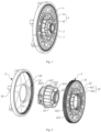
- the disclosure provides an electric machine including: a first revolving body 1, a second revolving body 2, a shaft assembly 3 and a guiding assembly 4.
- the shaft assembly 3 includes a first shaft 31, a second shaft 32 coaxially disposed within an inner circumference of the first shaft 31, and a bearing (not shown in the drawings) disposed between the first shaft 31 and the second shaft 32.
- An inner ring of the bearing is disposed at one of the first shaft 31 and the second shaft 32, and an outer ring of the bearing is disposed at the other of the first shaft 31 and the second shaft 32, such that the first shaft 31 can be rotated relative to the second shaft 32 about a central axis of the second shaft 32; and the bearing can be fixed in the shaft assembly 3 through, for example, a bearing retaining ring, such that the first shaft 31 and the second shaft 32 are unmovable with respect to each other in the axial direction.
- the first revolving body 1 is coaxially connected to the first shaft 31, and the first revolving body 1 includes an annular first adapter bracket 11, and a tubular structural portion 112 extending in an axial direction is disposed at an inner circumference of the first adapter bracket 11.
- the second revolving body 2 is coaxially connected to the second shaft 32, and the second revolving body 2 is disposed around and at an outer circumference of the first revolving body 1.
- the guiding assembly 4 is disposed between the tubular structural portion 112 and the first shaft 31 to restrict a movement of the first revolving body 1 relative to the first shaft 31 in a circumferential direction and a radial direction.
- the first revolving body 1 is a stator
- the first shaft 31 is a stationary shaft
- the second revolving body 2 is a rotor
- the second shaft 32 is a rotational shaft.
- the electric machine has a structure with an inner stator and an outer rotor.
- the first revolving body 1 is a rotor
- the first shaft 31 is a rotational shaft
- the second revolving body 2 is a stator
- the second shaft 32 is a stationary shaft.
- the electric machine has a structure with an inner rotor and an outer stator.
- the guiding assembly 4 can improve a coaxiality of the stator and the stationary shaft or a coaxiality of the rotor and the rotational shaft, which then ensures a uniform air gap between the stator and the rotor and improves an assembling quality of the electric machine.
- the electric machine according to the disclosure provides the guiding assembly 4 between the stator and the stationary shaft or between the rotor and the rotational shaft, which improves a coaxiality of the stator or rotor and the shaft assembly 3 and then improves an assembling quality of the electric machine; and since the guiding assembly 4 is adopted to replace the processing equipment in prior art, it simplifies the assembling process of the electric machine and also reduces the assembling cost of the electric machine.
- the first revolving body 1 is a stator, and the first shaft 31 is a stationary shaft.
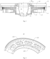
- the first revolving body 1 also includes a first module 12 disposed around and at an outer circumference of the first adapter bracket 11; the first module 12 is a stator module of the electric machine; and the stator module includes a stator module bracket 121, an iron core 122 disposed at an outer circumference of the stator module bracket 121, and a stator winding (not shown in the drawings) mounted on the iron core 122.
- the first adapter bracket 11 and the stator module bracket 121 are usually made of steel materials such as Q235 steel, which is shaped in a welding, casting or other process and then machined.
- the stator module bracket 121 has an internally hollow structure to improve its stiffness and also reduce its weight.
- a first double flange 123 is disposed at an inner circumference of the stator module bracket 121, and a group of bolt holes are formed at the first double flange 123; a second double flange 113 is disposed at the outer circumference of the first adapter bracket 11, and a group of bolt holes are formed at the second double flange 113; and the stator module bracket 121 and the first adapter bracket 11 may be connected together through a cooperation of the first double flange 123 and the second double flange 113.
- the iron core 122 is usually made of laminated silicon steel sheets, and winding coils are installed in slots of the iron core 122; and the iron core 122 is mounted to dovetail slots (not shown in the drawings) on the outer circumference of the stator module bracket 121 and thus fixed to the stator module bracket 121.
- the guiding assembly 4 includes a first inserting portion 41 and a first socketing portion 42 that are engaged with each other, the first inserting portion 41 is disposed at an inner circumference of the tubular structural portion 112 and extends in the axial direction, and the first socketing portion 42 is disposed at an outer circumference of the first shaft 31 and extends in the axial direction. There may be multiple first inserting portions 41 and multiple first socketing portions 42.
- the first inserting portion 41 includes a first guiding rib 411 protruding in the radial direction from the inner circumference of the tubular structural portion 112; and the first inserting portion 42 is a first guiding groove recessed in the radial direction from the outer circumference of the first shaft 31, and the first guiding groove has a width along the circumferential direction matched with a width of the first guiding rib 411 along the circumferential direction, so that a movement of the tubular structural portion 112 of the stator in the circumferential direction relative to the stationary shaft is restricted, which prevents a case in which a first inner flange 111 and a first outer flange 313 cannot be assembled with their centers being aligned due to insufficient coaxiality and accuracy after the stator and rotor have been assembled with one being surrounded by another.
- the first inserting portion 41 includes a second guiding rib 412 protruding in the radial direction from the inner circumference of the tubular structural portion 112, the second guiding rib 412 has an inner diameter larger than an inner diameter of the first guiding rib 411, and the second guiding rib 412 and the first guiding rib 411 are alternately arranged in the circumferential direction on the inner circumference, and the outer circumference of the first shaft 31 has an outer diameter matched with the inner diameter of the second guiding rib 412.
- the first shaft 31 and the inner circumference of the second guide 412 form a shaft-hole fit, and its tolerance fit here is preferably a clearance fit to restrict the movement of the tubular structural portion 112 of the stator in the radial direction relative to the stationary shaft.
- first guiding rib 411 and the second guiding rib 412 can be connected to an inner wall of the tubular structural portion 112 through countersunk screws or in other ways.
- the first guiding rib 411 and the second guiding rib 412 can be made of engineering plastics, metals such as aluminum, or composite materials such as phenolic laminated sheet.
- it would be beneficial that the materials of the first guiding rib 411 and the second guiding rib 412 are different from the material of the first shaft 31 to avoid crawling phenomenon which occurs when the first shaft 31 slides relative to the first guiding rib 411 and the second guiding rib 412.
- a first inner flange 111 is further disposed at an axial end of the tubular structural portion 112 of the first revolving body 1 near the first adapter bracket 11.
- the first inner flange 111 is a single flange, a group of bolt holes are formed at the single flange for connecting with the first shaft 31.
- the first shaft 31 is a stationary shaft, the first shaft 31 is usually made of steel materials such as low carbon steel, ductile iron, etc. which is shaped in a welding, casting or other process and then machined.
- the first shaft 31 includes a first end surface 311 and a second end surface 312 opposite to each other in its axial direction, a first outer flange 313 is disposed at the outer circumference of the first shaft 31 at a predetermined distance from the first end surface 311, and the tubular structural portion 112 and the first shaft 31 are connected together through a cooperation of the first inner flange 111 and the first outer flange 313.
- the cooperation of the first inner flange 111 and the first outer flange 313 may, for example, be a connection with a bolt and a stop.
- the guiding assembly 4 also includes a second inserting portion 43 and a second socketing portion 44 that are engaged with each other, the second inserting portion 43 is disposed at the outer circumference of the first shaft 31 near the first outer flange 313, the second socketing portion 44 is disposed at the inner circumference of the tubular structural portion 112 near the first inner flange 111, and the second socketing portion 44 has an inner diameter D2 larger than an inner diameter D1 of the first inserting portion 41.
- the second socketing portion 44 is formed by protruding in the radial direction from the inner circumference of the tubular structural portion 112
- the second inserting portion 43 is formed by protruding in the radial direction from the outer circumference of the first shaft 31
- an outer circumference of the second inserting portion 43 is matched with an inner circumference of the second socketing portion 44
- a fitting precision of the second inserting portion 43 and the second socketing portion 44 is higher than a fitting precision of the first inserting portion 41 and the first socketing portion 42.
- the shaft-hole fitting precision of the first inserting portion 41 and the first socketing portion 42 is H9/g9
- the shaft-hole fitting precision of the second inserting portion 43 and the second socketing portion 44 is H7/f7.
- the second inserting portion 43 is obtained by machining such as turning at the outer circumference of the first shaft 31, and the inner circumference of the second socketing portion 44 and the second inserting portion 43 form a shaft-hole fit, and its tolerance fit here is preferably a clearance fit.
- the clearance between the first inserting portion 41 and the first socketing portion 42 needs to be chosen to be large.
- the second inserting portion 43 can be pulled into the second socketing portion 44 when the bolts are connected at the first inner flange 111, which ensures that the coaxiality of the final assembly of the stator and the shaft assembly is at a high precision level.
- the second revolving body 2 includes an annular second adapter bracket 21 and a second module 22 disposed at an outer circumference of the second adapter bracket 21, a second inner flange 211 is disposed at an inner circumference of the second adapter bracket 21, a second outer flange 321 is disposed at the outer circumference of the second shaft 32, and the second revolving body 2 and the second shaft 32 are connected together through a cooperation of the second inner flange 211 and the second outer flange 321.
- the second revolving body 2 is a rotor
- the second shaft 32 is a rotational shaft
- the second shaft 32 is usually made of steel materials such as low carbon steel, ductile iron, etc., which is shaped in a welding, casting or other process and then machined.
- the second inner flange 211 of the second adapter bracket 21 and the second outer flange 321 are connected with bolts and stops so that the rotor and the rotational shaft are connected together.
- the second adapter bracket 21 is usually made of steel materials such as Q235 steel, which is shaped in a welding, casting or other process and then machined.
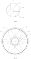
- the second adapter bracket 21 is a rotor bracket, and the second module 22 includes a plurality of magnetic pole modules 6; and the rotor bracket includes an adapter portion 51, two or more connecting arms 52 distributed radially on an outer circumference of the adapter portion 51, and a rotor ring 53 arranged coaxially with the two or more connecting arms 52; and the magnetic pole modules 6 are disposed at a mounting surface 53a of the rotor ring 53.
- the adapter portion 51, the connecting arms 52 and the rotor ring 53 can be fixed together by means of flange bolt connection, etc.
- each of the rotor ring 53 and the connecting arms 52 are provided as a hollow internal structural member, which improves the stiffness of the rotor bracket.
- the internally hollow connecting arm 52 can theoretically prevent a problem of magnetic pole attraction at the air gap between the rotor and the stator when the rotor is being mounted around the outer circumference of the stator.
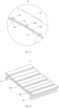
- the magnetic pole module 6 includes a substrate 6a and at least one magnet steel 6b disposed at the substrate 6a, and mounting portions 6c for matching with the mounting slots 53b are disposed at a side of the substrate 6a away from the magnet steel 6b.
- the magnetic pole module 6 is an excitation source of the electric machine, in which direct current coil excitation or permanent magnet excitation is commonly used; and permanent magnet excitation is used as an example in embodiments of the disclosure.
- the magnetic pole module 6 can be prefabricated at the factory.
- the magnet steel 6b is made of hard magnetic material such as NdFeB permanent magnet material, and several small-sized magnet steels 6b are assembled in the axial direction to form the magnetic pole module 6.
- the magnet steels 6b are fixed to the substrate 6a by gluing, mechanical connection such as screw connection, etc.
- the surface of the magnet steel 6 is protected by glue injection, magnetic pole boxes, etc., to isolate it from the outside air and reduce the risk of failure.
- the substrate 6a is made of ferromagnetic materials such as low carbon steel, electric iron, silicon steel, etc. by machining, which provides a magnetic flux path between adjacent magnetic pole modules 6.
- the mounting portion 6c of the substrate 6a is made of ferromagnetic materials such as low carbon steel, electric iron, silicon steel, etc. by machining, and can be fixed to the substrate 6a by bolting, welding, etc.; or the mounting portion 6c may be a part of the substrate 6a; and the mounting portion 6c has a shape matching with that of the mounting slot 53b of the rotor ring 53 to form a sliding rail structure that can move in the axial direction, so that the magnetic pole module 6 can be conveniently mounted to the mounting surface 53a of the rotor ring 53 and thus arranged opposite to the iron core 122 and the stator winding of the stator to form a uniform air gap.
- the above structure of the guiding assembly 4 can also applied to an electric machine having a structure with an inner rotor and an outer stator, and then the guiding assembly 4 is disposed between the rotor and the rotational shaft; in other words, the first revolving body 1 is a rotor, the first shaft 31 is a rotational shaft, the second revolving body 2 is a stator, and the second shaft 32 is a stationary shaft.
- FIG. 13 a structural schematic diagram of a rotor of an electric machine having a structure with an inner rotor and an outer stator is shown.
- the rotor includes an annular first adapter bracket 11 and a plurality of magnetic pole modules 6 disposed at an outer circumference of the first adapter bracket 11, a first inner flange 111 and a tubular structural portion 112 extending in the axial direction from the first inner flange 111 are disposed at an inner circumference of the first adapter bracket 11.
- the first shaft 31 in Fig. 8 is a rotational shaft
- the guiding assembly 4 is disposed between the tubular structural portion 112 of the rotor and the rotational shaft to restrict a movement of the rotor relative to the rotational shaft in the circumferential direction and the radial direction.
- a first outer flange 313 is disposed at an outer circumference of the rotational shaft, and the tubular structural portion 112 and the rotational shaft are connected together through a cooperation of the first inner flange 111 and the first outer flange 313.
- the guiding assembly 4 includes a first inserting portion 41 and a first socketing portion 42 that are engaged with each other, the first inserting portion 41 is disposed at an inner circumference of the tubular structural portion 112 and extends in the axial direction, and the first socketing portion 42 is disposed at an outer circumference of the first shaft 31 and extends in the axial direction. There may be multiple first inserting portions 41 and multiple first socketing portions 42.
- the guiding assembly 4 also includes a second inserting portion 43 and a second socketing portion 44 that are engaged with each other, the second inserting portion 43 is disposed at the outer circumference of the first shaft 31 near the first outer flange 313, the second socketing portion 44 is disposed at the inner circumference of the tubular structural portion 112 near the first inner flange 111, and the second socketing portion 44 has an inner diameter D2 larger than an inner diameter D1 of the first inserting portion 41.
- the rotor bracket includes an adapter portion 51, two or more connecting arms 52 distributed radially on an outer circumference of the adapter portion 51, and a rotor ring 53 arranged coaxially with the two or more connecting arms 52; magnetic pole modules 6 are disposed at a mounting surface 53a of the rotor ring 53; and with respect to the electric machines having a structure with an inner rotor and an outer stator, the mounting surface 53a is an outer circumference of the rotor ring 53.
- stator structure is similar to the stator structure in Figs. 4 and 5 , with the difference that there is no tubular structural portion 112 at the inner circumference of the first adapter bracket 11, the iron core 122 is disposed at the inner circumference of the stator module bracket 121, and the stator winding is mounted on the iron core 122 so as to be disposed opposite to the magnetic pole module 6 at the outer circumference of the rotor bracket to form a uniform air gap.
- each of the rotor ring 53 and the connecting arms 52 are provided as a hollow internal structural member, which improves the stiffness of the rotor bracket.
- the internally hollow connecting arm 52 can theoretically prevent a problem of magnetic pole attraction at the air gap between the rotor and the stator when the stator is being mounted around the outer circumference of the rotor.
- a maximum diameter of its stator or rotor exceeds a road transportation limit of 5m, it is necessary to prefabricate the stator and the rotor in a factory, and divide the stator into several stator sections and divide the rotor into several rotor sections before transportation.
- a maximum chord length of each stator section is smaller than an inner diameter of a paint dipping tank in the factory in order to ensure processing requirements of the stator winding.
- maximum widths of the stator section and the rotor section are smaller than the road transportation limit.
- embodiments of the disclosure also provide an assembling method for any of the electric machines as described above, wherein the assembling method includes:
- the first revolving body 1 is a stator
- the first shaft 31 is a stationary shaft
- the second revolving body 2 is a rotor
- the second shaft 32 is a rotational shaft
- the first revolving body 1 is a rotor
- the first shaft 31 is a rotational shaft
- the second revolving body 2 is a stator
- the second shaft 32 is a stationary shaft.
- the electric machine and the assembling method for the electric machine according to exemplary embodiments described above may be applied to various devices where an electric machine is required, such as but not limited to, wind turbines.
- the term "comprise” does not exclude other devices or steps; the article is intended to include one or more articles when not modified by a quantifier, and may be used interchangeably with “one or more articles”; the terms “first”, “second” or the like are used to designate names and are not intended to indicate any particular order. Any reference sign in the claims should not be construed as limiting the scope of protection. The functions of multiple parts in the claims may be implemented by a single hardware or software module. The presence of certain technical features in different dependent claims does not mean that these technical features cannot be combined for beneficial effect.
Claims (9)
- Machine électrique, comprenantun ensemble d'arbres (3) comprenant un premier arbre (31), un deuxième arbre (32) disposé coaxialement à l'intérieur d'une circonférence intérieure du premier arbre (31), et un palier disposé entre le premier arbre (31) et le deuxième arbre (32) ;un premier corps tournant (1) relié coaxialement au premier arbre (31), dans lequel le premier corps tournant (1) comprend un premier support adaptateur annulaire (11), et une partie structurelle tubulaire (112) s'étendant dans une direction axiale est disposée sur une circonférence intérieure du premier support adaptateur (11) ;un deuxième corps tournant (2) relié coaxialement au deuxième arbre (32) et disposé autour le premier corps tournant (1) et à une circonférence extérieure du celui-ci; etun ensemble de guidage (4) disposé entre la partie structurelle tubulaire (112) et le premier arbre (31) pour limiter le mouvement du premier corps tournant (1) par rapport au premier arbre (31) dans une direction circonférentielle et une direction radiale,caractérisé en ce que l'ensemble de guidage (4) comprend une première partie d'insertion (41) et une première partie d'emboîtement (42) qui sont engagées l'une dans l'autre, la première partie d'insertion (41) est disposée sur une circonférence intérieure de la partie structurelle tubulaire (112) et s'étend dans la direction axiale, et la première partie d'emboîtement (42) est disposée sur une circonférence extérieure du premier arbre (31) et s'étend dans la direction axiale,la première partie d'insertion (41) comprend une première nervure de guidage (411) faisant saillie dans la direction radiale à partir de la circonférence intérieure de la partie structurelle tubulaire (112), la première partie d'emboîtement (42) est une première rainure de guidage évidée dans la direction radiale à partir de la circonférence extérieure du premier arbre (31), et la première rainure de guidage a une largeur le long de la direction circonférentielle mise en correspondance avec une largeur de la première nervure de guidage (411) le long de la direction circonférentielle, etla première partie d'insertion (41) comprend en outre une deuxième nervure de guidage (412) faisant saillie dans la direction radiale à partir de la circonférence intérieure de la partie structurelle tubulaire (112), la deuxième nervure de guidage (412) a un diamètre intérieur supérieur à un diamètre intérieur de la première nervure de guidage (411), la deuxième nervure de guidage (412) et la première nervure de guidage (411) sont disposées alternativement dans la direction circonférentielle sur la circonférence intérieure, et la circonférence extérieure du premier arbre (31) a un diamètre extérieur mis en correspondance avec le diamètre intérieur de la deuxième nervure de guidage (412).
- Machine électrique selon la revendication 1, dans laquelle le premier corps tournant (1) est un stator, le premier arbre (31) est un arbre fixe, le deuxième corps tournant (2) est un rotor, et le deuxième arbre (32) est un arbre de rotation ; ou le premier corps tournant (1) est un rotor, le premier arbre (31) est un arbre de rotation, le deuxième corps tournant (2) est un stator, et le deuxième arbre (32) est un arbre fixe.
- Machine électrique selon la revendication 1, dans laquelle une première bride intérieure (111) est en outre disposée à une extrémité axiale de la partie structurelle tubulaire (112) à proximité du premier support adaptateur (11) ;le premier arbre (31) comprend une première surface d'extrémité (311) et une deuxième surface d'extrémité (312) opposées l'une à l'autre dans sa direction axiale, une première bride extérieure (313) est disposée sur la circonférence extérieure du premier arbre (31) à une distance prédéterminée de la première surface d'extrémité ; etla partie structurelle tubulaire (112) et le premier arbre (31) sont reliés par la coopération de la première bride intérieure (111) et de la première bride extérieure (313).
- Machine électrique selon la revendication 3, dans laquelle l'ensemble de guidage (4) comprend en outre une deuxième partie d'insertion (43) et une deuxième partie d'emboîtement (44) qui sont en prise l'une avec l'autre, la deuxième partie d'insertion (43) est disposée sur la circonférence extérieure du premier arbre (31) près de la première bride extérieure, la deuxième partie d'emboîtement (44) est disposée sur la circonférence intérieure de la partie structurelle tubulaire (112) près de la première bride intérieure, et la deuxième partie d'emboîtement (44) a un diamètre intérieur plus grand qu'un diamètre intérieur de la première partie d'insertion (41).
- Machine électrique selon la revendication 4, dans laquelle la deuxième partie d'emboîtement (44) est formée en faisant saillie dans la direction radiale à partir de la circonférence intérieure de la partie structurelle tubulaire (112), la deuxième partie d'insertion (43) est formée en faisant saillie dans la direction radiale à partir de la circonférence extérieure du premier arbre (31), une circonférence extérieure de la deuxième partie d'insertion (43) est mise en correspondance avec une circonférence intérieure de la deuxième partie d'emboîtement (44), et un jeu radial entre la deuxième partie d'insertion (43) et la deuxième partie d'emboîtement (44) est plus petit qu'un jeu radial entre la première partie d'insertion (41) et la première partie d'emboîtement (42).
- Machine électrique selon la revendication 1, dans laquelle le deuxième corps tournant (2) comprend un deuxième support adaptateur annulaire (21), une deuxième bride intérieure (211) est disposée sur une circonférence intérieure du deuxième support adaptateur (21), une deuxième bride extérieure (321) est disposée sur la circonférence extérieure du deuxième arbre (32), et le deuxième corps tournant (2) et le deuxième arbre (32) sont reliés ensemble par une coopération de la deuxième bride intérieure (211) et de la deuxième bride extérieure (321).
- Machine électrique selon la revendication 6, dans laquelle le premier support adaptateur (11) ou le deuxième support adaptateur (21) est un support de rotor ; le rotor comprend en outre une pluralité de modules de pôles magnétiques (6) disposés sur une circonférence extérieure du support de rotor ; le support de rotor comprend une partie adaptateur (51), deux ou plusieurs bras de connexion (52) répartis radialement sur une circonférence extérieure de la partie adaptateur (51), et une bague de rotor (53) disposée coaxialement avec les deux ou plusieurs bras de connexion (52) ; les modules de pôles magnétiques (6) sont disposés sur une surface de montage (53a) de la bague de rotor (53) ; la bague de rotor (53) et chacun des bras de connexion (52) sont constitués d'un élément structurel interne creux.
- Machine électrique selon la revendication 7, dans laquelle une pluralité de fentes de montage (53b) s'étendant dans la direction axiale est disposée à intervalles sur la surface de montage (53a) de la bague de rotor (53), le module de pôle magnétique (6) comprend un substrat (6a) et au moins un acier magnétique (6b) disposé sur le substrat (6), et des parties de montage (6c) destinées à correspondre aux fentes de montage (53b) sont disposées sur un côté du substrat (6a) à l'écart de l'acier magnétique (6b).
- Procédé d'assemblage d'une machine électrique selon l'une quelconque des revendications 1 à 8, comprenant :disposer le premier arbre (31) autour le deuxième arbre (32) et à la circonférence extérieure de celui-ci ;disposer la partie structurelle tubulaire (112) du premier corps tournant (1) autour premier arbre (31) et à la circonférence extérieure du de celui-ci à travers l'ensemble de guidage (4) ; etconnecter le deuxième corps tournant (2) coaxialement avec le deuxième arbre (32) de sorte que le deuxième corps tournant (2) soit disposé autour le premier corps tournant (1) et à la circonférence extérieure de celui-ci.
Applications Claiming Priority (2)
| Application Number | Priority Date | Filing Date | Title |
|---|---|---|---|
| CN201910440569.2A CN111987817B (zh) | 2019-05-24 | 2019-05-24 | 电机及电机的装配方法 |
| PCT/CN2020/072975 WO2020238265A1 (fr) | 2019-05-24 | 2020-01-19 | Moteur électrique et procédé d'assemblage pour moteur électrique |
Publications (4)
| Publication Number | Publication Date |
|---|---|
| EP3965263A1 EP3965263A1 (fr) | 2022-03-09 |
| EP3965263A4 EP3965263A4 (fr) | 2022-06-22 |
| EP3965263B1 true EP3965263B1 (fr) | 2023-07-26 |
| EP3965263C0 EP3965263C0 (fr) | 2023-07-26 |
Family
ID=73437499
Family Applications (1)
| Application Number | Title | Priority Date | Filing Date |
|---|---|---|---|
| EP20814881.7A Active EP3965263B1 (fr) | 2019-05-24 | 2020-01-19 | Machine électrique et procédé d'assemblage pour machine électrique |
Country Status (6)
| Country | Link |
|---|---|
| US (1) | US20220231557A1 (fr) |
| EP (1) | EP3965263B1 (fr) |
| CN (1) | CN111987817B (fr) |
| AU (1) | AU2020281866B2 (fr) |
| ES (1) | ES2954239T3 (fr) |
| WO (1) | WO2020238265A1 (fr) |
Families Citing this family (4)
| Publication number | Priority date | Publication date | Assignee | Title |
|---|---|---|---|---|
| CN113020828B (zh) * | 2021-02-03 | 2022-07-08 | 武汉船用机械有限责任公司 | 前导管的制造方法 |
| EP4184767A1 (fr) * | 2021-11-23 | 2023-05-24 | Abb Schweiz Ag | Ensemble de machine électrique et procédé de verrouillage de rotor sur un stator |
| CN114257297B (zh) * | 2021-12-30 | 2022-06-14 | 北京航天驭星科技有限公司 | 用于卫星测控的转台及卫星测控移动站 |
| NO347367B1 (en) * | 2022-06-01 | 2023-10-02 | Kongsberg Maritime As | Split electric machine |
Family Cites Families (37)
| Publication number | Priority date | Publication date | Assignee | Title |
|---|---|---|---|---|
| US5061868A (en) * | 1989-09-25 | 1991-10-29 | Nippon Densan Corporation | Spindle motor |
| US6304018B1 (en) * | 1995-11-21 | 2001-10-16 | Valeo Electrical Systems, Inc. | Externally-wound stator with improved magnetic transition |
| JP3723428B2 (ja) * | 2000-08-07 | 2005-12-07 | 日本電産サンキョー株式会社 | 動圧軸受モータ |
| CA2389483C (fr) * | 2002-06-06 | 2010-04-13 | General Electric Canada Inc. | Accouplement rotatif et a arbre double pour machine |
| JP3860096B2 (ja) * | 2002-08-09 | 2006-12-20 | アスモ株式会社 | ブラシレスモータ |
| WO2005108779A2 (fr) * | 2004-05-03 | 2005-11-17 | Wind Energy Group, Inc. | Éolienne génératrice d'électricité |
| JP2006136094A (ja) * | 2004-11-04 | 2006-05-25 | Funai Electric Co Ltd | 回転体駆動モータ装置とその環状マグネット組込方法 |
| CN101212151A (zh) * | 2006-12-29 | 2008-07-02 | 富准精密工业(深圳)有限公司 | 具有定子固定结构的马达 |
| US7679249B2 (en) * | 2007-03-02 | 2010-03-16 | Kari Appa | Contra rotating generator |
| EP2063117B1 (fr) * | 2007-11-26 | 2016-09-14 | Siemens Aktiengesellschaft | Agencement pour un générateur à entraînement direct, générateur à entraînement direct, éolienne et procédé pour le montage d'un générateur |
| CN201153225Y (zh) * | 2008-01-23 | 2008-11-19 | 上海荟懿环保科技有限公司 | 风力发电机 |
| US20090309438A1 (en) * | 2008-06-12 | 2009-12-17 | Alex Horng | Motor Structure |
| CN101615823B (zh) * | 2008-06-24 | 2012-07-04 | 建准电机工业股份有限公司 | 马达 |
| EP2157314B2 (fr) * | 2008-08-20 | 2018-12-19 | Siemens Aktiengesellschaft | Éolienne |
| CN101902090B (zh) * | 2009-05-26 | 2012-12-05 | 建准电机工业股份有限公司 | 马达、风扇及其定子装置 |
| US8179005B2 (en) * | 2010-01-25 | 2012-05-15 | Sunonwealth Electric Machine Industry Co., Ltd. | Motor |
| CN201956823U (zh) * | 2011-03-28 | 2011-08-31 | 国电联合动力技术有限公司 | 一种将大型永磁电机转子装入定子内的工装 |
| JP2013021810A (ja) * | 2011-07-11 | 2013-01-31 | Jtekt Corp | 回転電機 |
| JP2014003807A (ja) * | 2012-06-19 | 2014-01-09 | Toyota Industries Corp | 回転電機 |
| JP2014137088A (ja) * | 2013-01-16 | 2014-07-28 | Nippon Densan Corp | 軸受装置、モータおよび送風ファン |
| JP5840151B2 (ja) * | 2013-01-17 | 2016-01-06 | 三菱電機株式会社 | 回転電機 |
| CN203104151U (zh) * | 2013-03-01 | 2013-07-31 | 常州亚通杰威电机有限公司 | 一种电机总成用转子组件 |
| KR101462766B1 (ko) * | 2013-03-13 | 2014-11-20 | 삼성전기주식회사 | 스핀들 모터 |
| JP6326938B2 (ja) * | 2014-04-24 | 2018-05-23 | スズキ株式会社 | 電動回転機 |
| CN104052204B (zh) * | 2014-07-02 | 2016-09-14 | 杭州务实科技有限公司 | 发电机装配定位装置 |
| JP6002721B2 (ja) * | 2014-07-17 | 2016-10-05 | シナノケンシ株式会社 | 軸受装置及びモータ |
| ES2564053B1 (es) * | 2014-09-17 | 2016-12-22 | Soler & Palau Research, S.L. | Motor eléctrico con amortiguación de vibraciones |
| CN204465189U (zh) * | 2015-04-07 | 2015-07-08 | 珠海格力节能环保制冷技术研究中心有限公司 | 分段式电机转子和电机 |
| CN106487155A (zh) * | 2015-08-31 | 2017-03-08 | 德昌电机(深圳)有限公司 | 液泵、电机及其轴套单元 |
| CN107040072A (zh) * | 2016-02-03 | 2017-08-11 | 德昌电机(深圳)有限公司 | 电机及其支撑座 |
| EP3219984B1 (fr) * | 2016-03-14 | 2019-01-02 | Siemens Aktiengesellschaft | Agencement de palier coulissant pour turbine éolienne |
| JP2017184560A (ja) * | 2016-03-31 | 2017-10-05 | 日本電産株式会社 | モータ及びモータの製造方法 |
| CN105827033B (zh) * | 2016-05-23 | 2018-10-16 | 珠海格力节能环保制冷技术研究中心有限公司 | 一种电机支架及采用其的电机 |
| CN108233586A (zh) * | 2016-12-22 | 2018-06-29 | 日本电产(东莞)有限公司 | 马达 |
| CN207977795U (zh) * | 2017-12-28 | 2018-10-16 | 杭州奇虎节能技术有限公司 | 一种具有高精度动平衡的永磁转子 |
| CN207753507U (zh) * | 2017-12-29 | 2018-08-21 | 深圳市正德智控股份有限公司 | 定子支架及外转子电机 |
| CN109245351A (zh) * | 2018-10-12 | 2019-01-18 | 台州市金宇机电有限公司 | 一种电动车用轮毂电机 |
-
2019
- 2019-05-24 CN CN201910440569.2A patent/CN111987817B/zh active Active
-
2020
- 2020-01-19 AU AU2020281866A patent/AU2020281866B2/en active Active
- 2020-01-19 EP EP20814881.7A patent/EP3965263B1/fr active Active
- 2020-01-19 WO PCT/CN2020/072975 patent/WO2020238265A1/fr unknown
- 2020-01-19 ES ES20814881T patent/ES2954239T3/es active Active
-
2021
- 2021-01-19 US US17/615,370 patent/US20220231557A1/en active Pending
Also Published As
| Publication number | Publication date |
|---|---|
| WO2020238265A1 (fr) | 2020-12-03 |
| AU2020281866A1 (en) | 2022-01-06 |
| AU2020281866B2 (en) | 2023-09-21 |
| ES2954239T3 (es) | 2023-11-21 |
| CN111987817B (zh) | 2023-11-24 |
| CN111987817A (zh) | 2020-11-24 |
| US20220231557A1 (en) | 2022-07-21 |
| EP3965263C0 (fr) | 2023-07-26 |
| EP3965263A1 (fr) | 2022-03-09 |
| EP3965263A4 (fr) | 2022-06-22 |
Similar Documents
| Publication | Publication Date | Title |
|---|---|---|
| EP3965263B1 (fr) | Machine électrique et procédé d'assemblage pour machine électrique | |
| CN101459354B (zh) | 直接驱动发电机和风力涡轮机 | |
| US9154024B2 (en) | Systems and methods for improved direct drive generators | |
| CN101521414B (zh) | 用于直接驱动发电机的配置、直接驱动发电机、风力涡轮机以及发电机的组装方法 | |
| US9030071B2 (en) | Electrical machines | |
| US20170117763A1 (en) | Axial flux machine | |
| KR20180011189A (ko) | 영구 자석 발전기의 구성 방법 | |
| KR20190031241A (ko) | 2축 일체형 모터 | |
| JP4775760B2 (ja) | シリンダ形リニアモータおよびそのガイド装置 | |
| US20220403875A1 (en) | Magnetic suspension bearing device, compressor and method of adjusting gap of catcher bearing | |
| US10714990B2 (en) | Rotating electrical machine and robot device | |
| JP5728704B2 (ja) | レゾルバの取付構造 | |
| KR102527294B1 (ko) | 축방향 자속 회전기기 | |
| AU2020374439B2 (en) | Clamping assembly and assembly method for permanent magnet motor | |
| EP2485373B1 (fr) | Machine sans roulement | |
| US11070116B2 (en) | Rotor for a rotating electrical machine | |
| JP2006109655A (ja) | ダイレクトドライブモータ | |
| JP2005312124A (ja) | 回転電機の構造 | |
| CN112448504B (zh) | 电机的转子、电机及电机的装配方法 | |
| CN114552922B (zh) | 一种双转子轴向磁通电机装配工艺 | |
| CN112737228B (zh) | 永磁电机的装配方法及拆卸方法 | |
| JP2012249519A (ja) | ダイレクトドライブモータ、搬送装置および半導体製造装置 | |
| JP7135786B2 (ja) | 固定子、磁気軸受、回転機械 | |
| US10720804B2 (en) | Permanent magnet machine with segmented sleeve for magnets | |
| KR102535350B1 (ko) | 발전기의 인코더용 진동저감장치 |
Legal Events
| Date | Code | Title | Description |
|---|---|---|---|
| STAA | Information on the status of an ep patent application or granted ep patent |
Free format text: STATUS: THE INTERNATIONAL PUBLICATION HAS BEEN MADE |
|
| PUAI | Public reference made under article 153(3) epc to a published international application that has entered the european phase |
Free format text: ORIGINAL CODE: 0009012 |
|
| STAA | Information on the status of an ep patent application or granted ep patent |
Free format text: STATUS: REQUEST FOR EXAMINATION WAS MADE |
|
| 17P | Request for examination filed |
Effective date: 20211129 |
|
| AK | Designated contracting states |
Kind code of ref document: A1 Designated state(s): AL AT BE BG CH CY CZ DE DK EE ES FI FR GB GR HR HU IE IS IT LI LT LU LV MC MK MT NL NO PL PT RO RS SE SI SK SM TR |
|
| A4 | Supplementary search report drawn up and despatched |
Effective date: 20220524 |
|
| RIC1 | Information provided on ipc code assigned before grant |
Ipc: H02K 7/18 20060101ALN20220518BHEP Ipc: H02K 15/16 20060101ALI20220518BHEP Ipc: H02K 7/00 20060101ALI20220518BHEP Ipc: H02K 1/2786 20220101ALI20220518BHEP Ipc: H02K 1/30 20060101ALI20220518BHEP Ipc: H02K 1/18 20060101AFI20220518BHEP |
|
| DAV | Request for validation of the european patent (deleted) | ||
| DAX | Request for extension of the european patent (deleted) | ||
| REG | Reference to a national code |
Ref country code: DE Ref legal event code: R079 Ref document number: 602020014622 Country of ref document: DE Free format text: PREVIOUS MAIN CLASS: H02K0001120000 Ipc: H02K0001180000 Ref country code: DE Ref legal event code: R079 |
|
| GRAP | Despatch of communication of intention to grant a patent |
Free format text: ORIGINAL CODE: EPIDOSNIGR1 |
|
| STAA | Information on the status of an ep patent application or granted ep patent |
Free format text: STATUS: GRANT OF PATENT IS INTENDED |
|
| RIC1 | Information provided on ipc code assigned before grant |
Ipc: H02K 7/18 20060101ALN20230223BHEP Ipc: H02K 15/16 20060101ALI20230223BHEP Ipc: H02K 7/00 20060101ALI20230223BHEP Ipc: H02K 1/2786 20220101ALI20230223BHEP Ipc: H02K 1/30 20060101ALI20230223BHEP Ipc: H02K 1/18 20060101AFI20230223BHEP |
|
| INTG | Intention to grant announced |
Effective date: 20230322 |
|
| GRAS | Grant fee paid |
Free format text: ORIGINAL CODE: EPIDOSNIGR3 |
|
| GRAA | (expected) grant |
Free format text: ORIGINAL CODE: 0009210 |
|
| STAA | Information on the status of an ep patent application or granted ep patent |
Free format text: STATUS: THE PATENT HAS BEEN GRANTED |
|
| AK | Designated contracting states |
Kind code of ref document: B1 Designated state(s): AL AT BE BG CH CY CZ DE DK EE ES FI FR GB GR HR HU IE IS IT LI LT LU LV MC MK MT NL NO PL PT RO RS SE SI SK SM TR |
|
| REG | Reference to a national code |
Ref country code: CH Ref legal event code: EP Ref country code: RO Ref legal event code: EPE |
|
| REG | Reference to a national code |
Ref country code: IE Ref legal event code: FG4D |
|
| REG | Reference to a national code |
Ref country code: DE Ref legal event code: R096 Ref document number: 602020014622 Country of ref document: DE |
|
| U01 | Request for unitary effect filed |
Effective date: 20230824 |
|
| U07 | Unitary effect registered |
Designated state(s): AT BE BG DE DK EE FI FR IT LT LU LV MT NL PT SE SI Effective date: 20230831 |
|
| REG | Reference to a national code |
Ref country code: LT Ref legal event code: MG9D |
|
| REG | Reference to a national code |
Ref country code: ES Ref legal event code: FG2A Ref document number: 2954239 Country of ref document: ES Kind code of ref document: T3 Effective date: 20231121 |
|
| PG25 | Lapsed in a contracting state [announced via postgrant information from national office to epo] |
Ref country code: GR Free format text: LAPSE BECAUSE OF FAILURE TO SUBMIT A TRANSLATION OF THE DESCRIPTION OR TO PAY THE FEE WITHIN THE PRESCRIBED TIME-LIMIT Effective date: 20231027 |
|
| PG25 | Lapsed in a contracting state [announced via postgrant information from national office to epo] |
Ref country code: IS Free format text: LAPSE BECAUSE OF FAILURE TO SUBMIT A TRANSLATION OF THE DESCRIPTION OR TO PAY THE FEE WITHIN THE PRESCRIBED TIME-LIMIT Effective date: 20231126 |
|
| U20 | Renewal fee paid [unitary effect] |
Year of fee payment: 5 Effective date: 20231219 |
|
| PG25 | Lapsed in a contracting state [announced via postgrant information from national office to epo] |
Ref country code: RS Free format text: LAPSE BECAUSE OF FAILURE TO SUBMIT A TRANSLATION OF THE DESCRIPTION OR TO PAY THE FEE WITHIN THE PRESCRIBED TIME-LIMIT Effective date: 20230726 Ref country code: NO Free format text: LAPSE BECAUSE OF FAILURE TO SUBMIT A TRANSLATION OF THE DESCRIPTION OR TO PAY THE FEE WITHIN THE PRESCRIBED TIME-LIMIT Effective date: 20231026 Ref country code: IS Free format text: LAPSE BECAUSE OF FAILURE TO SUBMIT A TRANSLATION OF THE DESCRIPTION OR TO PAY THE FEE WITHIN THE PRESCRIBED TIME-LIMIT Effective date: 20231126 Ref country code: HR Free format text: LAPSE BECAUSE OF FAILURE TO SUBMIT A TRANSLATION OF THE DESCRIPTION OR TO PAY THE FEE WITHIN THE PRESCRIBED TIME-LIMIT Effective date: 20230726 Ref country code: GR Free format text: LAPSE BECAUSE OF FAILURE TO SUBMIT A TRANSLATION OF THE DESCRIPTION OR TO PAY THE FEE WITHIN THE PRESCRIBED TIME-LIMIT Effective date: 20231027 |
|
| PGFP | Annual fee paid to national office [announced via postgrant information from national office to epo] |
Ref country code: RO Payment date: 20231220 Year of fee payment: 5 |
|
| PG25 | Lapsed in a contracting state [announced via postgrant information from national office to epo] |
Ref country code: PL Free format text: LAPSE BECAUSE OF FAILURE TO SUBMIT A TRANSLATION OF THE DESCRIPTION OR TO PAY THE FEE WITHIN THE PRESCRIBED TIME-LIMIT Effective date: 20230726 |
|
| PGFP | Annual fee paid to national office [announced via postgrant information from national office to epo] |
Ref country code: ES Payment date: 20240207 Year of fee payment: 5 |