EP3957529B1 - Control method for hybrid vehicle and control device for hybrid vehicle - Google Patents
Control method for hybrid vehicle and control device for hybrid vehicle Download PDFInfo
- Publication number
- EP3957529B1 EP3957529B1 EP19924649.7A EP19924649A EP3957529B1 EP 3957529 B1 EP3957529 B1 EP 3957529B1 EP 19924649 A EP19924649 A EP 19924649A EP 3957529 B1 EP3957529 B1 EP 3957529B1
- Authority
- EP
- European Patent Office
- Prior art keywords
- air density
- vehicle speed
- engine
- correction
- target
- Prior art date
- Legal status (The legal status is an assumption and is not a legal conclusion. Google has not performed a legal analysis and makes no representation as to the accuracy of the status listed.)
- Active
Links
Images


Classifications
-
- F—MECHANICAL ENGINEERING; LIGHTING; HEATING; WEAPONS; BLASTING
- F02—COMBUSTION ENGINES; HOT-GAS OR COMBUSTION-PRODUCT ENGINE PLANTS
- F02D—CONTROLLING COMBUSTION ENGINES
- F02D29/00—Controlling engines, such controlling being peculiar to the devices driven thereby, the devices being other than parts or accessories essential to engine operation, e.g. controlling of engines by signals external thereto
- F02D29/06—Controlling engines, such controlling being peculiar to the devices driven thereby, the devices being other than parts or accessories essential to engine operation, e.g. controlling of engines by signals external thereto peculiar to engines driving electric generators
-
- B—PERFORMING OPERATIONS; TRANSPORTING
- B60—VEHICLES IN GENERAL
- B60K—ARRANGEMENT OR MOUNTING OF PROPULSION UNITS OR OF TRANSMISSIONS IN VEHICLES; ARRANGEMENT OR MOUNTING OF PLURAL DIVERSE PRIME-MOVERS IN VEHICLES; AUXILIARY DRIVES FOR VEHICLES; INSTRUMENTATION OR DASHBOARDS FOR VEHICLES; ARRANGEMENTS IN CONNECTION WITH COOLING, AIR INTAKE, GAS EXHAUST OR FUEL SUPPLY OF PROPULSION UNITS IN VEHICLES
- B60K6/00—Arrangement or mounting of plural diverse prime-movers for mutual or common propulsion, e.g. hybrid propulsion systems comprising electric motors and internal combustion engines
- B60K6/20—Arrangement or mounting of plural diverse prime-movers for mutual or common propulsion, e.g. hybrid propulsion systems comprising electric motors and internal combustion engines the prime-movers consisting of electric motors and internal combustion engines, e.g. HEVs
- B60K6/42—Arrangement or mounting of plural diverse prime-movers for mutual or common propulsion, e.g. hybrid propulsion systems comprising electric motors and internal combustion engines the prime-movers consisting of electric motors and internal combustion engines, e.g. HEVs characterised by the architecture of the hybrid electric vehicle
- B60K6/46—Series type
-
- B—PERFORMING OPERATIONS; TRANSPORTING
- B60—VEHICLES IN GENERAL
- B60W—CONJOINT CONTROL OF VEHICLE SUB-UNITS OF DIFFERENT TYPE OR DIFFERENT FUNCTION; CONTROL SYSTEMS SPECIALLY ADAPTED FOR HYBRID VEHICLES; ROAD VEHICLE DRIVE CONTROL SYSTEMS FOR PURPOSES NOT RELATED TO THE CONTROL OF A PARTICULAR SUB-UNIT
- B60W10/00—Conjoint control of vehicle sub-units of different type or different function
- B60W10/04—Conjoint control of vehicle sub-units of different type or different function including control of propulsion units
- B60W10/06—Conjoint control of vehicle sub-units of different type or different function including control of propulsion units including control of combustion engines
-
- B—PERFORMING OPERATIONS; TRANSPORTING
- B60—VEHICLES IN GENERAL
- B60W—CONJOINT CONTROL OF VEHICLE SUB-UNITS OF DIFFERENT TYPE OR DIFFERENT FUNCTION; CONTROL SYSTEMS SPECIALLY ADAPTED FOR HYBRID VEHICLES; ROAD VEHICLE DRIVE CONTROL SYSTEMS FOR PURPOSES NOT RELATED TO THE CONTROL OF A PARTICULAR SUB-UNIT
- B60W10/00—Conjoint control of vehicle sub-units of different type or different function
- B60W10/04—Conjoint control of vehicle sub-units of different type or different function including control of propulsion units
- B60W10/08—Conjoint control of vehicle sub-units of different type or different function including control of propulsion units including control of electric propulsion units, e.g. motors or generators
-
- B—PERFORMING OPERATIONS; TRANSPORTING
- B60—VEHICLES IN GENERAL
- B60W—CONJOINT CONTROL OF VEHICLE SUB-UNITS OF DIFFERENT TYPE OR DIFFERENT FUNCTION; CONTROL SYSTEMS SPECIALLY ADAPTED FOR HYBRID VEHICLES; ROAD VEHICLE DRIVE CONTROL SYSTEMS FOR PURPOSES NOT RELATED TO THE CONTROL OF A PARTICULAR SUB-UNIT
- B60W10/00—Conjoint control of vehicle sub-units of different type or different function
- B60W10/24—Conjoint control of vehicle sub-units of different type or different function including control of energy storage means
- B60W10/26—Conjoint control of vehicle sub-units of different type or different function including control of energy storage means for electrical energy, e.g. batteries or capacitors
-
- B—PERFORMING OPERATIONS; TRANSPORTING
- B60—VEHICLES IN GENERAL
- B60W—CONJOINT CONTROL OF VEHICLE SUB-UNITS OF DIFFERENT TYPE OR DIFFERENT FUNCTION; CONTROL SYSTEMS SPECIALLY ADAPTED FOR HYBRID VEHICLES; ROAD VEHICLE DRIVE CONTROL SYSTEMS FOR PURPOSES NOT RELATED TO THE CONTROL OF A PARTICULAR SUB-UNIT
- B60W20/00—Control systems specially adapted for hybrid vehicles
- B60W20/10—Controlling the power contribution of each of the prime movers to meet required power demand
- B60W20/15—Control strategies specially adapted for achieving a particular effect
-
- F—MECHANICAL ENGINEERING; LIGHTING; HEATING; WEAPONS; BLASTING
- F02—COMBUSTION ENGINES; HOT-GAS OR COMBUSTION-PRODUCT ENGINE PLANTS
- F02D—CONTROLLING COMBUSTION ENGINES
- F02D11/00—Arrangements for, or adaptations to, non-automatic engine control initiation means, e.g. operator initiated
- F02D11/06—Arrangements for, or adaptations to, non-automatic engine control initiation means, e.g. operator initiated characterised by non-mechanical control linkages, e.g. fluid control linkages or by control linkages with power drive or assistance
- F02D11/10—Arrangements for, or adaptations to, non-automatic engine control initiation means, e.g. operator initiated characterised by non-mechanical control linkages, e.g. fluid control linkages or by control linkages with power drive or assistance of the electric type
- F02D11/105—Arrangements for, or adaptations to, non-automatic engine control initiation means, e.g. operator initiated characterised by non-mechanical control linkages, e.g. fluid control linkages or by control linkages with power drive or assistance of the electric type characterised by the function converting demand to actuation, e.g. a map indicating relations between an accelerator pedal position and throttle valve opening or target engine torque
-
- F—MECHANICAL ENGINEERING; LIGHTING; HEATING; WEAPONS; BLASTING
- F02—COMBUSTION ENGINES; HOT-GAS OR COMBUSTION-PRODUCT ENGINE PLANTS
- F02D—CONTROLLING COMBUSTION ENGINES
- F02D35/00—Controlling engines, dependent on conditions exterior or interior to engines, not otherwise provided for
-
- B—PERFORMING OPERATIONS; TRANSPORTING
- B60—VEHICLES IN GENERAL
- B60K—ARRANGEMENT OR MOUNTING OF PROPULSION UNITS OR OF TRANSMISSIONS IN VEHICLES; ARRANGEMENT OR MOUNTING OF PLURAL DIVERSE PRIME-MOVERS IN VEHICLES; AUXILIARY DRIVES FOR VEHICLES; INSTRUMENTATION OR DASHBOARDS FOR VEHICLES; ARRANGEMENTS IN CONNECTION WITH COOLING, AIR INTAKE, GAS EXHAUST OR FUEL SUPPLY OF PROPULSION UNITS IN VEHICLES
- B60K6/00—Arrangement or mounting of plural diverse prime-movers for mutual or common propulsion, e.g. hybrid propulsion systems comprising electric motors and internal combustion engines
- B60K6/20—Arrangement or mounting of plural diverse prime-movers for mutual or common propulsion, e.g. hybrid propulsion systems comprising electric motors and internal combustion engines the prime-movers consisting of electric motors and internal combustion engines, e.g. HEVs
- B60K6/22—Arrangement or mounting of plural diverse prime-movers for mutual or common propulsion, e.g. hybrid propulsion systems comprising electric motors and internal combustion engines the prime-movers consisting of electric motors and internal combustion engines, e.g. HEVs characterised by apparatus, components or means specially adapted for HEVs
- B60K6/40—Arrangement or mounting of plural diverse prime-movers for mutual or common propulsion, e.g. hybrid propulsion systems comprising electric motors and internal combustion engines the prime-movers consisting of electric motors and internal combustion engines, e.g. HEVs characterised by apparatus, components or means specially adapted for HEVs characterised by the assembly or relative disposition of components
-
- B—PERFORMING OPERATIONS; TRANSPORTING
- B60—VEHICLES IN GENERAL
- B60W—CONJOINT CONTROL OF VEHICLE SUB-UNITS OF DIFFERENT TYPE OR DIFFERENT FUNCTION; CONTROL SYSTEMS SPECIALLY ADAPTED FOR HYBRID VEHICLES; ROAD VEHICLE DRIVE CONTROL SYSTEMS FOR PURPOSES NOT RELATED TO THE CONTROL OF A PARTICULAR SUB-UNIT
- B60W2510/00—Input parameters relating to a particular sub-units
- B60W2510/06—Combustion engines, Gas turbines
- B60W2510/0638—Engine speed
-
- B—PERFORMING OPERATIONS; TRANSPORTING
- B60—VEHICLES IN GENERAL
- B60W—CONJOINT CONTROL OF VEHICLE SUB-UNITS OF DIFFERENT TYPE OR DIFFERENT FUNCTION; CONTROL SYSTEMS SPECIALLY ADAPTED FOR HYBRID VEHICLES; ROAD VEHICLE DRIVE CONTROL SYSTEMS FOR PURPOSES NOT RELATED TO THE CONTROL OF A PARTICULAR SUB-UNIT
- B60W2510/00—Input parameters relating to a particular sub-units
- B60W2510/06—Combustion engines, Gas turbines
- B60W2510/0657—Engine torque
-
- B—PERFORMING OPERATIONS; TRANSPORTING
- B60—VEHICLES IN GENERAL
- B60W—CONJOINT CONTROL OF VEHICLE SUB-UNITS OF DIFFERENT TYPE OR DIFFERENT FUNCTION; CONTROL SYSTEMS SPECIALLY ADAPTED FOR HYBRID VEHICLES; ROAD VEHICLE DRIVE CONTROL SYSTEMS FOR PURPOSES NOT RELATED TO THE CONTROL OF A PARTICULAR SUB-UNIT
- B60W2510/00—Input parameters relating to a particular sub-units
- B60W2510/08—Electric propulsion units
- B60W2510/081—Speed
-
- B—PERFORMING OPERATIONS; TRANSPORTING
- B60—VEHICLES IN GENERAL
- B60W—CONJOINT CONTROL OF VEHICLE SUB-UNITS OF DIFFERENT TYPE OR DIFFERENT FUNCTION; CONTROL SYSTEMS SPECIALLY ADAPTED FOR HYBRID VEHICLES; ROAD VEHICLE DRIVE CONTROL SYSTEMS FOR PURPOSES NOT RELATED TO THE CONTROL OF A PARTICULAR SUB-UNIT
- B60W2510/00—Input parameters relating to a particular sub-units
- B60W2510/24—Energy storage means
- B60W2510/242—Energy storage means for electrical energy
- B60W2510/244—Charge state
-
- B—PERFORMING OPERATIONS; TRANSPORTING
- B60—VEHICLES IN GENERAL
- B60W—CONJOINT CONTROL OF VEHICLE SUB-UNITS OF DIFFERENT TYPE OR DIFFERENT FUNCTION; CONTROL SYSTEMS SPECIALLY ADAPTED FOR HYBRID VEHICLES; ROAD VEHICLE DRIVE CONTROL SYSTEMS FOR PURPOSES NOT RELATED TO THE CONTROL OF A PARTICULAR SUB-UNIT
- B60W2520/00—Input parameters relating to overall vehicle dynamics
- B60W2520/10—Longitudinal speed
-
- B—PERFORMING OPERATIONS; TRANSPORTING
- B60—VEHICLES IN GENERAL
- B60W—CONJOINT CONTROL OF VEHICLE SUB-UNITS OF DIFFERENT TYPE OR DIFFERENT FUNCTION; CONTROL SYSTEMS SPECIALLY ADAPTED FOR HYBRID VEHICLES; ROAD VEHICLE DRIVE CONTROL SYSTEMS FOR PURPOSES NOT RELATED TO THE CONTROL OF A PARTICULAR SUB-UNIT
- B60W2540/00—Input parameters relating to occupants
- B60W2540/10—Accelerator pedal position
-
- B—PERFORMING OPERATIONS; TRANSPORTING
- B60—VEHICLES IN GENERAL
- B60W—CONJOINT CONTROL OF VEHICLE SUB-UNITS OF DIFFERENT TYPE OR DIFFERENT FUNCTION; CONTROL SYSTEMS SPECIALLY ADAPTED FOR HYBRID VEHICLES; ROAD VEHICLE DRIVE CONTROL SYSTEMS FOR PURPOSES NOT RELATED TO THE CONTROL OF A PARTICULAR SUB-UNIT
- B60W2552/00—Input parameters relating to infrastructure
- B60W2552/25—Road altitude
-
- B—PERFORMING OPERATIONS; TRANSPORTING
- B60—VEHICLES IN GENERAL
- B60W—CONJOINT CONTROL OF VEHICLE SUB-UNITS OF DIFFERENT TYPE OR DIFFERENT FUNCTION; CONTROL SYSTEMS SPECIALLY ADAPTED FOR HYBRID VEHICLES; ROAD VEHICLE DRIVE CONTROL SYSTEMS FOR PURPOSES NOT RELATED TO THE CONTROL OF A PARTICULAR SUB-UNIT
- B60W2555/00—Input parameters relating to exterior conditions, not covered by groups B60W2552/00, B60W2554/00
- B60W2555/20—Ambient conditions, e.g. wind or rain
-
- B—PERFORMING OPERATIONS; TRANSPORTING
- B60—VEHICLES IN GENERAL
- B60W—CONJOINT CONTROL OF VEHICLE SUB-UNITS OF DIFFERENT TYPE OR DIFFERENT FUNCTION; CONTROL SYSTEMS SPECIALLY ADAPTED FOR HYBRID VEHICLES; ROAD VEHICLE DRIVE CONTROL SYSTEMS FOR PURPOSES NOT RELATED TO THE CONTROL OF A PARTICULAR SUB-UNIT
- B60W2555/00—Input parameters relating to exterior conditions, not covered by groups B60W2552/00, B60W2554/00
- B60W2555/40—Altitude
-
- B—PERFORMING OPERATIONS; TRANSPORTING
- B60—VEHICLES IN GENERAL
- B60W—CONJOINT CONTROL OF VEHICLE SUB-UNITS OF DIFFERENT TYPE OR DIFFERENT FUNCTION; CONTROL SYSTEMS SPECIALLY ADAPTED FOR HYBRID VEHICLES; ROAD VEHICLE DRIVE CONTROL SYSTEMS FOR PURPOSES NOT RELATED TO THE CONTROL OF A PARTICULAR SUB-UNIT
- B60W2710/00—Output or target parameters relating to a particular sub-units
- B60W2710/06—Combustion engines, Gas turbines
- B60W2710/0644—Engine speed
-
- B—PERFORMING OPERATIONS; TRANSPORTING
- B60—VEHICLES IN GENERAL
- B60W—CONJOINT CONTROL OF VEHICLE SUB-UNITS OF DIFFERENT TYPE OR DIFFERENT FUNCTION; CONTROL SYSTEMS SPECIALLY ADAPTED FOR HYBRID VEHICLES; ROAD VEHICLE DRIVE CONTROL SYSTEMS FOR PURPOSES NOT RELATED TO THE CONTROL OF A PARTICULAR SUB-UNIT
- B60W2710/00—Output or target parameters relating to a particular sub-units
- B60W2710/06—Combustion engines, Gas turbines
- B60W2710/0666—Engine torque
-
- B—PERFORMING OPERATIONS; TRANSPORTING
- B60—VEHICLES IN GENERAL
- B60W—CONJOINT CONTROL OF VEHICLE SUB-UNITS OF DIFFERENT TYPE OR DIFFERENT FUNCTION; CONTROL SYSTEMS SPECIALLY ADAPTED FOR HYBRID VEHICLES; ROAD VEHICLE DRIVE CONTROL SYSTEMS FOR PURPOSES NOT RELATED TO THE CONTROL OF A PARTICULAR SUB-UNIT
- B60W2710/00—Output or target parameters relating to a particular sub-units
- B60W2710/08—Electric propulsion units
- B60W2710/086—Power
-
- B—PERFORMING OPERATIONS; TRANSPORTING
- B60—VEHICLES IN GENERAL
- B60W—CONJOINT CONTROL OF VEHICLE SUB-UNITS OF DIFFERENT TYPE OR DIFFERENT FUNCTION; CONTROL SYSTEMS SPECIALLY ADAPTED FOR HYBRID VEHICLES; ROAD VEHICLE DRIVE CONTROL SYSTEMS FOR PURPOSES NOT RELATED TO THE CONTROL OF A PARTICULAR SUB-UNIT
- B60W2720/00—Output or target parameters relating to overall vehicle dynamics
- B60W2720/10—Longitudinal speed
-
- B—PERFORMING OPERATIONS; TRANSPORTING
- B60—VEHICLES IN GENERAL
- B60Y—INDEXING SCHEME RELATING TO ASPECTS CROSS-CUTTING VEHICLE TECHNOLOGY
- B60Y2200/00—Type of vehicle
- B60Y2200/90—Vehicles comprising electric prime movers
- B60Y2200/92—Hybrid vehicles
-
- B—PERFORMING OPERATIONS; TRANSPORTING
- B60—VEHICLES IN GENERAL
- B60Y—INDEXING SCHEME RELATING TO ASPECTS CROSS-CUTTING VEHICLE TECHNOLOGY
- B60Y2300/00—Purposes or special features of road vehicle drive control systems
- B60Y2300/91—Battery charging
-
- F—MECHANICAL ENGINEERING; LIGHTING; HEATING; WEAPONS; BLASTING
- F02—COMBUSTION ENGINES; HOT-GAS OR COMBUSTION-PRODUCT ENGINE PLANTS
- F02D—CONTROLLING COMBUSTION ENGINES
- F02D2200/00—Input parameters for engine control
- F02D2200/02—Input parameters for engine control the parameters being related to the engine
- F02D2200/04—Engine intake system parameters
- F02D2200/0414—Air temperature
-
- F—MECHANICAL ENGINEERING; LIGHTING; HEATING; WEAPONS; BLASTING
- F02—COMBUSTION ENGINES; HOT-GAS OR COMBUSTION-PRODUCT ENGINE PLANTS
- F02D—CONTROLLING COMBUSTION ENGINES
- F02D2200/00—Input parameters for engine control
- F02D2200/50—Input parameters for engine control said parameters being related to the vehicle or its components
- F02D2200/501—Vehicle speed
-
- F—MECHANICAL ENGINEERING; LIGHTING; HEATING; WEAPONS; BLASTING
- F02—COMBUSTION ENGINES; HOT-GAS OR COMBUSTION-PRODUCT ENGINE PLANTS
- F02D—CONTROLLING COMBUSTION ENGINES
- F02D2200/00—Input parameters for engine control
- F02D2200/70—Input parameters for engine control said parameters being related to the vehicle exterior
-
- F—MECHANICAL ENGINEERING; LIGHTING; HEATING; WEAPONS; BLASTING
- F02—COMBUSTION ENGINES; HOT-GAS OR COMBUSTION-PRODUCT ENGINE PLANTS
- F02D—CONTROLLING COMBUSTION ENGINES
- F02D2250/00—Engine control related to specific problems or objectives
- F02D2250/18—Control of the engine output torque
-
- Y—GENERAL TAGGING OF NEW TECHNOLOGICAL DEVELOPMENTS; GENERAL TAGGING OF CROSS-SECTIONAL TECHNOLOGIES SPANNING OVER SEVERAL SECTIONS OF THE IPC; TECHNICAL SUBJECTS COVERED BY FORMER USPC CROSS-REFERENCE ART COLLECTIONS [XRACs] AND DIGESTS
- Y02—TECHNOLOGIES OR APPLICATIONS FOR MITIGATION OR ADAPTATION AGAINST CLIMATE CHANGE
- Y02T—CLIMATE CHANGE MITIGATION TECHNOLOGIES RELATED TO TRANSPORTATION
- Y02T10/00—Road transport of goods or passengers
- Y02T10/60—Other road transportation technologies with climate change mitigation effect
- Y02T10/62—Hybrid vehicles
Definitions
- the present invention relates to a control method and control device for a hybrid vehicle that includes a generator driven by an internal combustion engine.
- Hybrid vehicles having an internal combustion engine and a generator configured to be driven by the internal combustion engine in a drive system are known.
- JP2007-216841A discloses taking into consideration intake air density when setting the target output of an internal combustion engine.
- correction coefficients are set in accordance with the temperature and pressure of the intake air, and the required internal combustion engine output is multiplied by these correction coefficients, thereby setting the target output.
- the correction coefficients When the intake air temperature is high or the intake air pressure is low, the correction coefficients apparently increase the target output, and the desired generated power can be generated by the generator even under the condition of low air density (paragraph 0031).
- JP2015-098217A which shows the features of the preamble of claim 1.
- the throttle opening of the internal combustion engine can be increased in order to take in a larger volume of air into the cylinders.
- this entails the problem that the increased throttle opening may result in poor fuel economy.
- the pressure in the intake pipe rises (in other words, the intake negative pressure decreases), so that the EGR rate decreases, which leads to an increase in pumping loss resulting in poor fuel efficiency.
- An object of the present invention is to provide a control method and control device for a hybrid vehicle that take into consideration the problems described above.
- a method of controlling a hybrid vehicle as a reference example in which the drive system includes an internal combustion engine, a generator is configured to be driven by the internal combustion engine, and a battery is configured to be charged by the generated power of the generator.
- the target generated power of the generator is set, and the target engine output, which is the target output of the internal combustion engine corresponding to the target generated power, is calculated.
- the air density in the environment in which the vehicle travels is detected for a decrease in air density
- the target engine output is corrected based on the detected air density
- the generated power of the generator is made to follow the target generated power (air density correction of target engine output).
- the implementation of the air density correction is then permitted or stopped in accordance with the operating state of the driving system.
- a hybrid vehicle control device is provided.
- Figure 1 shows the configuration of the overall drive system S of the hybrid vehicle according to one embodiment of the invention.
- the drive system (hereinafter, simply referred to as “drive system”) S is mounted on a hybrid vehicle and forms a propulsion apparatus for the vehicle.
- the drive system S includes an internal combustion engine 1, an electric motor for power generation (hereinafter “power generating motor”) 2, and an electric motor for running (hereinafter called a “travel motor”) 3.
- power generating motor an electric motor for power generation
- travel motor an electric motor for running
- hybrid vehicle means a vehicle equipped with an electric motor as a power source besides the internal combustion engine 1 related to the drive means of the vehicle, and in the present embodiment, the power generated by driving the power generating motor 2 with the internal combustion engine 1 is supplied to the travel motor 3 directly or via the battery 4.
- the output shaft or crankshaft 11 of the internal combustion engine (hereinafter simply referred to as "engine") 1 is connected to the rotary shaft 21 of the power generating motor 2 via the gear train Ga.
- the torque of the engine 1 is transmitted to the power generating motor 2 at a prescribed gear ratio through the gear train Ga, and the power generating motor 2 operates.
- the power generating motor 2 which is connected to the battery 4 and electrically connected to the travel motor 3, supplies the power that is generated by receiving power from the engine 1 to the travel motor 3 or the battery 4.
- the electric power supplied from the power generating motor 2 to the travel motor 3 and from the battery 4 to the travel motor 3 are controlled by a motor controller 301 according to the driving state of the vehicle and the state of charge of the battery 4.
- the electrical connections among the power generating motor 2, the travel motor 3, and the battery 4 are schematically indicated by a double-dot dashed line.
- a rotary shaft 31 of the travel motor 3 is connected to a ring gear of a differential 5 via a gear train Gb.
- the torque of the travel motor 3 is transmitted to the differential 5 at a prescribed gear ratio through the gear train Gb, and further distributed to left and right drive shafts 6, 6 via the differential 5 to rotate drive wheel 7 to propel the vehicle.
- the travel motor 3 is composed of a motor/generator that can operate not only as an electric motor but also as a generator, and is capable of receiving power from the drive wheel 7 via the gear train Gb and generating electric power.
- the electric power generated by the travel motor 3 can be supplied to the battery 4 and used to charge the battery 4.
- the operation of the engine 1, the power generating motor 2, and the travel motor 3 is integrally controlled by a vehicle controller 101.
- the vehicle controller 101 and an engine controller 201 which will be described further below, are constituted by a microcomputer equipped with a central processing unit (CPU), various storage units such as ROM and RAM, an input/output interface, etc., as an electronic control unit.
- Information regarding various parameters indicating the driving state of the vehicle is input to the vehicle controller 101.
- a signal indicating the degree of depression of the accelerator pedal by the driver hereinafter referred to as "accelerator opening" APO
- a signal indicating the vehicle travel speed hereinafter referred to as "vehicle speed” VSP
- a signal indicating the rotational speed Neng of engine 1 a signal indicating the rotational speed Nmg1 of the power generating motor 2
- a signal indicating the rotational speed Nmg2 of the travel motor 3 are input to vehicle controller 101.
- a signal indicating the air temperature Tatm outside the vehicle is input as information on the environmental conditions in which the vehicle travels.
- sensors for the detection of various parameters are provided: an accelerator opening sensor 111 that detects the accelerator opening APO, a vehicle speed sensor 112 that detects the vehicle speed VSP, an engine rotational speed sensor 113 that detects the rotational speed Neng of the engine 1 as the number of revolutions per unit time (hereinafter called "engine rotational speed"), a power generation motor rotational speed sensor 114 that detects the rotational speed Nmg1 of the power generating motor 2, a travel motor rotational speed sensor 115 that detects the rotational speed Nmg2 of the travel motor 3, and an air temperature sensor 116 that detects the air temperature Tatm.
- the vehicle controller 101 performs a prescribed operation based on various input signals and outputs a command signal to the engine controller 201 and the motor controller 301.
- the engine controller 201 controls the operation of the engine 1 via an engine control device such as a throttle valve and a fuel injection valve based on a command signal from the vehicle controller 101.
- the motor controller 301 controls the power supplied from the power generating motor 2 and the battery 4 to the travel motor 3 based on a command signal from the vehicle controller 101, and controls the operation of the travel motor 3.
- a controller is provided for controlling the operation of the power generating motor 2 and the battery 4.
- the vehicle controller 101 sets the target generated power of the power generating motor 2 with respect to the control of the engine 1, and also calculates the target engine output, which is the target output of the engine 1 according to the target generated power.
- the vehicle controller 101 then instructs the engine controller 201 to operate at the target engine output. More specifically, the vehicle controller 101 calculates the engine rotational speed and engine torque that define the operating point for the engine 1 with the lowest fuel consumption rate [g/kWh] (hereinafter may be referred to as "best fuel consumption rotational speed” and “best fuel consumption torque,” respectively) as the engine rotational speed and engine torque that can realize the target engine output; that is, the vehicle controller instructs the operation at the best fuel consumption point (hereinafter referred to as "best fuel consumption point") in accordance with the target engine output.
- the engine controller 201 sets the target engine rotational speed and the target engine torque to the best fuel consumption rotational speed and the best fuel consumption torque, respectively, to control the actual torque and rotational speed of engine 1 for realizing the target engine torque and target engine rotational speed.
- fuel consumption refers to the fuel consumption rate [g/kWh].
- the engine controller 201 introduces a correction based on air density (hereinafter called "air density correction”) to control the engine torque.
- the air density correction is generally realized as a correction for increasing the target engine output such that the actual generated power of the power generating motor 2 can follow the target generated power regardless of air density in response to decreases in air density in the environment in which the vehicle travels. During travel decreased air density occurs not only at high altitudes, but also in high-temperature areas or even when the temperature increases in the same area.
- the throttle opening of the engine 1 can be increased in order to bring a greater amount of air into the cylinders of engine 1 in order to realize a target engine output that is increased with respect to a decreased air density. Consequently, in the present embodiment, since the pressure in the intake pipe is increased and the intake negative pressure is decreased, the EGR rate decreases, which results in increased pumping loss and poor fuel efficiency.
- Figure 2 shows the effect of the air density correction on fuel consumption from the standpoint point of variations in fuel consumption with respect to an increase in air temperature Tair.
- the target engine torque tTRQ which is the value indicated by A
- the throttle opening TVO is increased by the engine control based on the corrected target engine torque tTRQ
- the ratio of the recirculated exhaust gas to the total intake gas that is, the EGR rate Regr
- the fuel consumption rate of the engine 1 increases (the value after the increase is indicated by B), and the operating efficiency of the engine 1 deteriorates.
- an operation for suppressing the deterioration in operating efficiency is introduced, wherein the execution of the air density correction is stopped while permitting a decrease in actual engine torque TRQ to the extent possible.
- Figure 3 conceptually shows an operation according to this embodiment (hereinafter may be referred to as "correction cancellation") for stopping the execution of the air density correction.
- the upper portion of Figure 3 shows the case in which the basic setting is performed
- the middle portion shows the case in which the air density correction is performed
- the lower portion shows the case in which the air density correction is stopped by a correction cancellation.
- the vehicle controller 101 calculates a target engine torque tTRQ (VCM-designated torque) according to the target generated power of the power generation motor 2, and outputs the calculated target engine torque to the engine controller 201.
- the engine controller 201 then adds a torque equivalent to the friction to the target engine torque, and the post-addition target engine torque (ECM target torque) is set as the final target engine torque.
- the engine controller 201 outputs a command signal based on the final target engine torque to an engine control device such as a fuel injection valve.
- the engine 1 basically outputs a torque equivalent to the target engine torque (VCM-designated torque) tTRQ instructed by the vehicle controller 101.
- the torque equivalent to the friction and the torque for the air density correction are added to the target engine torque tTRQ instructed by the vehicle controller 101, and the post-addition target engine torque is set as the final target engine torque.
- the torque of the air density correction compensates for the shortfall due to a decrease in air density.
- the "air density correction” is realized by adding the torque of the air density correction to the target engine torque. Due to the instruction based on the final target engine torque, engine 1 outputs a torque equivalent to the target engine torque tTRQ indicated by the vehicle controller 101.
- the vehicle controller 101 carries out an operation in which the torque for the correction cancellation corresponding to the air density correction amount is subtracted from the target engine torque tTRQ according to the target generated power of the power generating motor 2, and the target engine torque (VCM-designated torque) after subtraction is output to the engine controller 201.
- the engine controller 201 adds the torque equivalent to friction and the torque for the air density correction to the target engine torque, and the post-addition target engine torque is set as the final target engine torque. Therefore, in the case in which the execution of the air density correction is stopped, the final target engine torque is reduced by the torque of the correction cancellation as compared to the case in which the air density correction is performed.
- the torque output by the engine 1 is also lower than the target engine torque tTRQ according to the target generated power due to the fact that the final target engine torque is lowered by the torque of the correction cancellation.
- the air density correction operation is stopped by previously subtracting the correction cancellation torque from the target engine torque tTRQ according to the target generated power, but the operation of stopping the implementation of the air density correction is not limited thereto. For example, it is possible to stop the operation of adding the torque for the air density correction itself, or to add the torque for the air density correction but subtract the torque for the correction cancellation from the target engine torque after the addition.
- Figure 4 shows the region in which the correction cancellation is performed (hereinafter may be referred to as the "cancellation region").
- the correction cancellation is performed while permitting the actual engine torque to decrease to the extent possible, in other words, to the extent that the engine torque does not substantially affect the management of the state of charge of the battery 4, even if the engine torque is insufficient for the target engine torque tTRQ.
- the cancellation region makes the area clear, and in Figure 4 , the cancellation region is indicated by the shaded area.
- the cancellation region is determined based on the relationship between the vehicle speed VSP and the state of charge SOC of the battery 4.
- the air density correction is basically applied to a decrease in air density Dair
- a cancellation region is set for stopping the execution of the air density correction. This is because the lower the air density Dair, the greater the air density correction that must be applied and the larger the throttle opening that is required to secure the output, which causes the fuel consumption rate to deteriorate.
- a cancellation region is set. If the air density Dair is less than a second prescribed density Dthrl, which is lower than the first prescribed density Dthrh, a cancellation region is set over the entire area of the vehicle speed VSP, whereas the cancellation region is set for the case in which the vehicle speed VSP is in the high vehicle speed range from the second prescribed density Dthrl to the first prescribed density Dthrh.
- the determination is made when the vehicle has returned from the high vehicle speed range to the low vehicle speed range (hereinafter referred to as "cancellation of high vehicle speed determination"), a difference, that is, a hysteresis is applied to the determination threshold (Vthr).
- Vthr the determination threshold
- the relatively high first prescribed vehicle speed Vthrh is used as the threshold
- the second prescribed vehicle speed Vthrl which is lower than the first prescribed vehicle speed Vthrh, is used as the threshold.
- the range for setting the cancellation region is limited to the case in which the state of charge SOC of the battery 4 is greater than or equal to a prescribed SOC1.
- a threshold value (SOC1) is also set for determining the state of charge SOC of the battery 4, and hysteresis is applied thereto. Specifically, when the charged state SOC rises (during charging), it is determined that the charged state is a high charged state when the first prescribed charge state SOC1a or higher, which is relatively high, is determined.
- Figure 5 shows the effects of air density correction and correction cancellation on fuel consumption for two different operating points A and B.
- Operating point A is the operating point (engine rotational speed Nengl) set for the low vehicle speed range
- operating point B is the operating point (engine rotational speed Nengh) set for the high vehicle speed range.
- both operating points A and B are the best fuel economy points of the engine 1.
- Figure 6 shows the operation schedule according to the vehicle speed VSP of the engine 1 at the time of flat road driving.
- the solid line Lstr indicates the start line of the engine 1 for the different states of charge SOCs of the battery 4
- the double-dotted line Lstp indicates the stop line of the engine 1 for each state of charge for SOC in association with the start line.
- the start lines Lstrh, Lstrm, and Lstrl correspond to cases in which the state of charge SOC is high in that order
- the operation stop lines Lstph, Lstpm, and Lstpl also correspond to cases in which the state of charge SOC is similarly high in that order.
- the dotted line indicates the output at the best fuel consumption point of the engine 1 (the generated power of the power generating motor 2, hereinafter referred to as "fixed point output") Pout.
- the output Pout1 on the low output side corresponds to operating point A shown in Figure 5
- the output Pout2 on the high output side corresponds to the operating point B.
- hysteresis is applied between operating point B and the case in which the output returns from operating point B to operating point A.
- the operation schedule of the engine 1 is determined according to the required output for the drive system S, the vehicle speed VSP, and the state of charge SOC of the battery 4.
- the engine 1 starts at the time point when the required output is increased and the corresponding start line Lstr is reached under the actual state of charge SOC.
- the power generating motor 2 starts power generation and the battery 4 is charged, so that the operation stop line Lstp is sequentially switched to those on the high charging state side.
- the engine 1 stops when the operation stop line Lstp corresponding to the state of charge SOC is reached.
- the engine 1 is started when the required output reaches the starting line Lstrm at a prescribed vehicle speed Vthr (e.g., the first prescribed vehicle speed Vthrh). Thereafter, if the high charge state is maintained, since the operation stop line Lstph is lower than the required output, the engine 1 is not stopped and combustion is continued (continuous combustion region).
- Vthr e.g., the first prescribed vehicle speed Vthrh
- the engine 1 is not stopped and combustion is continued (continuous combustion region).
- Pout2 the energy consumption of the battery 4 exceeds the power supplied by the engine 1, so the state of charge SOC is kept low
- the operation stop line Lstp is switched to the low state of charge side (e.g., Lstpm), and combustion is continued.
- the engine 1 starts and stops repeatedly (intermittent combustion region) due to the repeated passing of the stop line Lstp due in turn to the rise of the state of charge SOC after the required output reaches the start line Lstr (e.g., start line Lstrl or the lower charging side start line).
- the mode changes intermittently between the series hybrid driving mode, in which the power generating motor 2 is driven by the engine 1 and the battery 4 is charged, and EV driving mode, in which the engine 1 is stopped and the vehicle is driven by the travel motor 3.
- the state of charge SOC of the battery 4 increases or decreases, and the starting and stopping of engine 1 is repeated.
- the frequency of stopping the engine 1 is decreased.
- the cancellation region can be determined not only by the vehicle speed VSP, but also by the combustion state of the engine 1. For example, it is possible to determine whether the combustion state is continuous or intermittent from the relationship between the fixed point output Pout and the required output, and it is also possible to define the range in which the required output exceeds the fixed point output Pout (indicated by reference numeral A in Figure 6 ) as the continuous combustion region, and the remaining range (indicated by reference numeral B) as the intermittent combustion region.
- the vehicle speed Vthra at which the required output matches the fixed point output Pout becomes the "prescribed vehicle speed.”
- the vehicle speed Vthrh ( ⁇ Vthra) is set as the boundary between the continuous combustion region and the intermittent combustion region
- the extent to which the continuous combustion region can be expanded to the low vehicle speed side from the range A that is, the extent to which the boundary between the continuous fuel region A and the intermittent combustion region B can be pushed down from the state shown in the figure to the low vehicle speed side is determined by the charge management of the battery 4.
- Figures 7 to 9 show the operation of the vehicle controller 101
- Figure 10 shows the operation of the engine controller 201.
- the vehicle controller 101 and the engine controller 201 are programmed to perform the controls shown in Figures 7 to 9 and 10 at prescribed intervals.
- Figure 7 is a flowchart of the target engine torque calculation routine.
- the target generated power of the power generating motor 2 is calculated based on the operating state of the vehicle.
- the target engine output which is the target output of the engine 1, is calculated based on the target generated power.
- the target engine rotational speed is calculated based on the target engine output.
- the calculation of the target engine rotational speed is based on a search for the optimal fuel consumption point corresponding to the target engine output.
- an optimal fuel consumption line (hereinafter referred to as " ⁇ line") for the engine 1 that connects the optimal fuel consumption points on the equal output line for each output is predetermined and is converted into data and stored in the vehicle controller 101.
- the vehicle controller 101 specifies the optimal fuel consumption point corresponding to the target engine output on the ⁇ -line, and calculates the rotational speed at the optimal fuel consumption point as the target engine rotation speed.
- the target engine torque is calculated. Specifically, the torque at the optimal fuel consumption point is calculated as the target engine torque.
- S106 it is determined whether a correction is in the area where a cancellation correction should be performed. This determination is made with reference to the map data shown in Figure 4 and will be explained in detail with reference to Figure 8 . If it is in the cancellation region, the process proceeds to S107, and if it is not in the cancellation region, the control by the routine is ended.
- FIG 8 is a flowchart of the correction cancellation determination routine (hereinafter referred to as the "cancellation determination routine").
- the cancellation determination routine is executed as a process called in S106 of the flowchart shown in Figure 7 .
- the driving state of the vehicle is read. Specifically, the vehicle speed VSP and the air density Dair are read.
- the air density Dair is calculated based on the air temperature Tatm by a separately set air density calculation routine.
- the battery 4 state of charge SOC is read.
- the state of charge SOC can be calculated based on the open circuit voltage and charge/discharge current of the battery 4 using a separately set state of charge calculation routine.
- the open circuit voltage of the battery 4 can be detected by the voltage sensor 117, and the charge/discharge current can be detected by the current sensor 118.
- S203 it is determined whether the state of charge SOC is greater than or equal to the prescribed state of charge SOC1, that is, whether the battery 4 is in the highly charged state. As previously described, hysteresis is applied in the prescribed state of charge SOC1 at the time of charging and discharging the battery 4. If it is in a high state of charge, the process proceeds to S204. On the other hand, if it is not in a high state of charge but in a low state of charge, it is not in the area (cancellation region) where a correction cancellation should be performed, and the process returns to the flowchart shown in Figure 7 . In this case, the determination of S106 is denied, and air density correction is permitted.
- the high vehicle speed determination flag Fvsp is set to 0 (that is, the initial value set at the start of the system S is 0), and when the vehicle speed VSP reaches the first prescribed vehicle speed Vthrh from the low vehicle speed range and the vehicle experiences a vehicle speed greater than or equal to the first prescribed vehicle speed Vthrh, this flag is switched to 1. Then, when the vehicle speed VSP is lowered to the second prescribed vehicle speed Vthrl and deviates from the high vehicle speed range, this flag is reset to 0.
- whether the high vehicle speed determination flag Fvsp is 0 or 1 determines whether the boundary between when the low vehicle speed range and the high vehicle speed range (Vthrh, Vthrl) is switched.
- the process proceeds to S205, and if it is 1, the process proceeds to step S301 shown in Figure 9 .
- S205 it is determined whether the vehicle speed VSP is less than the first prescribed vehicle speed Vthrh. If the vehicle speed is less than the first prescribed vehicle speed Vthrh, the process proceeds to S206, and if the vehicle speed is greater than or equal to the first prescribed vehicle speed Vthrh, the process proceeds to S208.
- S206 it is determined whether the air density Dair is less than the second prescribed density Dthrl. If the density is less than the second prescribed density Dthrl, the process proceeds to S207. On the other hand, if the density is greater than or equal to the second prescribed density Dthrl, it is assumed that the density is not in the cancellation region, and the process returns to the flowchart shown in the Figure 7 . In this case, the determination of S106 is denied, and air density correction is permitted.
- S208 it is determined whether the air density Dair is less than the first prescribed density Dthrh. If the air density is less than the first prescribed density Dthrh, the process proceeds to S209. On the other hand, if the air density is greater than or equal to the first prescribed density Dthrh, it is assumed that the air density is not in the cancellation region, and the process returns to the flowchart shown in Figure 7 . In this case, the determination of S106 is denied, and air density correction is permitted.
- Figure 9 shows a flowchart of the process performed in section A of the cancellation determination routine shown in Figure 8 .
- S301 it is determined whether the vehicle speed VSP is greater than or equal to the second prescribed vehicle speed Vthrl. If the speed is greater than or equal to the second prescribed vehicle speed Vthrh, the process proceeds to S302. If the speed is less than the second prescribed vehicle speed Vthrl, the process proceeds to S304.
- S302 it is determined whether the air density Dair is less than the first prescribed density Dthrh. If the air density is less than the first prescribed density Dthrh, the process proceeds to S303. On the other hand, if the air density is greater than or equal to the first prescribed density Dthrh, it is assumed that the air density is not in the cancellation region, and the process returns to the flowchart shown in Figure 7 . In this case, the determination of S106 is denied, and air density correction is permitted.
- S304 it is determined whether the air density Dair is less than the second prescribed density Dthrl. If the air density is less than the second prescribed density Dthrl, the process proceeds to S305. On the other hand, if the density is greater than or equal to the second prescribed density Dthrl, it is assumed that the density is not in the cancellation region and the process returns to the flowchart shown in Figure 7 . In this case, the determination of S106 is denied, and the air density correction is permitted.
- Figure 10 is a flowchart of the engine control routine.
- the target engine torque is corrected by the air density correction to compensate for the decrease in air density Dair. Specifically, the torque equivalent to the air density decrease is added to the target engine torque.
- the post-addition torque is set as the final target engine torque.
- the vehicle controller 101 and the engine controller 201 constitute the "engine controller.”
- the function of the "target engine output calculation section” is realized by the processing steps of S103 to S105
- the function of the "air density detection section” is realized by the processing step of S201
- the function of the "target engine output correction section” is realized by the processing step of S402
- the function of the "correction execution switching section” is realized by the processing steps of S106, S107, S203 to S209, and S301 to S305, respectively.
- the function to be provided by the "engine controller” can be not only shared between the vehicle controller 101 and the engine controller 201, but also provided by a single controller.
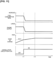
- FIG 11 shows an example in which the battery 4 state of charge SOC is restored. If the battery 4 is in a low charge state, the air density correction is performed by determining that the air density is not in the cancellation region even though the air density Dair is low (cancellation execution flag off). When the state of charge SOC rises and reaches the prescribed state of charge SOC1 (time t11), there is a switch to the determination that the air density is in the cancellation region (cancellation execution flag on), and the correction cancellation is performed. As a result, the execution of air density correction is stopped, and the efficiency of operation is promoted by reducing the fuel consumption while reducing engine torque.
- the change in fuel economy (fuel consumption rate) and engine output have a gradient, which is due to a control for the purpose of preventing sudden changes.
- Figure 12 shows an example in which the state of charge SOC of the battery 4 has deteriorated. If the battery 4 is in a high charge state, it is assumed that the air density Dair is in a low environment and the execution of the air density correction is stopped by the determination that the air density is in the cancellation region (cancellation execution flag on). When the state of charge SOC decreases and reaches the prescribed state of charge SOC1 (time t21), there is a switch to the determination that the air density is not in the correction cancellation region (cancellation execution flag off), and the execution of the correction cancellation is stopped. As a result, the air density correction is performed, and the engine torque increases.
- Figures 13 and 14 show an example in which the vehicle speed VSP increases or decreases and the state of charge SOC is constant.
- Figure 13 shows the case in which there is no variation in air density Dair
- Figure 14 shows the case in which there is variation in air density Dair.
- the air density Dair continues to be less than the first prescribed density Dthrh and the correction cancellation is continued.
- the vehicle speed VSP reaches the second prescribed vehicle speed Vthrl (time t33)
- the execution of correction cancellation is stopped.
- the air density Dair decreases during a period from the low vehicle speed range until the vehicle speed VSP reaches the first prescribed vehicle speed Vthrh on the high vehicle speed side.
- the density falls below the second prescribed density Dthrl (time t41)
- it is determined that the density is in the cancellation region and the correction cancellation is performed.
- the vehicle speed VSP reaches the first prescribed vehicle speed Vthrh (time t42)
- the determination that the vehicle is in the cancellation region is maintained due to continuance of the state in which the air density Dair is below the first prescribed density Dthrh.
- the drive system S of the hybrid vehicle according to the present embodiment is configured as described above, and the effects obtained by this embodiment are described below.
- the shortage of the actual output of the engine 1 can be solved to bring the generated power of the power generating motor 2 closer to the target generated power. Then, if the correction cancellation operation is introduced and the execution of this air density correction is permitted or stopped according to the operating state of the drive system S, the air density can be corrected for, and it is thus possible to avoid the deterioration in fuel efficiency that would have occurred and to construct a drive system S with improved overall efficiency.
- whether the correction should be canceled is determined by the state of charge SOC of the battery 4.
- the state of charge SOC of the battery 4 When the battery 4 is in a low charge state, it is possible to secure a suitable engine output regardless of actual air density and to promote the charging of the battery 4 by performing the air density correction.
- the correction is not performed and the execution of the air density correction is stopped; it is thus possible to avoid a deterioration in the fuel efficiency due to the air density correction while securing the engine output necessary for maintaining the charge state.
- the possibility of correction cancellation is determined by the vehicle speed VSP, and during driving in a vehicle speed range lower than the prescribed vehicle speed Vthr, since the contribution of the engine 1 to the output formation of the drive system S is relatively low, it is possible to secure the required engine output while allowing a deterioration in fuel efficiency to the extent possible.
- the possibility of correction cancellation is determined by the vehicle speed VSP, and during driving in a vehicle speed range lower than the prescribed vehicle speed Vthr, since the contribution of the engine 1 to the output formation of the drive system S is relatively low, it is possible to secure the required engine output while allowing a deterioration in fuel efficiency to the extent possible.
- the engine contribution is relatively high
- by stopping the execution of air density correction it is possible to promote efficiency by reducing the fuel economy of the engine 1 while fulfilling the requirements for output formation.
- the combustion state of the engine 1 is used to perform the air density correction during the intermittent combustion operation to stop the air density correction during the continuous combustion operation to ensure sufficient engine output; during intermittent combustion, the charging of battery 4 is prompted, and the frequency of stopping the engine 1 in drive mode (EV driving mode) is secured, while improving efficiency by reducing the fuel consumption of engine 1 during continuous combustion operation.
- the engine 1 is operated at its best fuel consumption point, and the target engine torque and the target engine speed corresponding to the target engine output are selected from the prescribed best fuel consumption points for the engine 1.
- the setting of the target engine torque is not limited in this way, and this setting can be made in consideration of the power performance requirement for the drive system S, or requirements for sound and vibration control.
- power performance requirement when there is a power requirement (hereinafter referred to as "power performance requirement") besides a requirement related to the charge state SOC of the battery 4 with respect to the engine torque and the engine speed, then priority is given to the formation of an output that satisfies the power performance requirement for the engine 1.
- a power performance requirement there is the case in which power is supplied from the power generation motor 2 in addition to the battery 4 in order to achieve the required acceleration with respect to the depression of the accelerator pedal by the driver. In this case, it is preferable that sufficient engine output be formed by performing the air density correction without executing the correction cancellation.
- the upper limit for sound and vibration control is set for the engine torque and engine speed, and the target engine torque, etc., is limited to this upper limit or less. For example, if the target engine rotational speed according to the target generated power exceeds the upper limit speed, the target engine rotational speed is updated according to the upper limit rotational speed.
- correction cancellation can be realized by reducing not only the target engine torque but also the target engine output itself or lowering the target engine rotational speed.
- the outside air temperature, barometric pressure, and altitude of the travel region are parameters that can replace air density.
Landscapes
- Engineering & Computer Science (AREA)
- Chemical & Material Sciences (AREA)
- Combustion & Propulsion (AREA)
- Mechanical Engineering (AREA)
- Transportation (AREA)
- General Engineering & Computer Science (AREA)
- Automation & Control Theory (AREA)
- Hybrid Electric Vehicles (AREA)
- Electric Propulsion And Braking For Vehicles (AREA)
- Control Of Vehicle Engines Or Engines For Specific Uses (AREA)
- Electrical Control Of Air Or Fuel Supplied To Internal-Combustion Engine (AREA)
Applications Claiming Priority (1)
| Application Number | Priority Date | Filing Date | Title |
|---|---|---|---|
| PCT/JP2019/016314 WO2020213056A1 (ja) | 2019-04-16 | 2019-04-16 | ハイブリッド車両の制御方法およびハイブリッド車両の制御装置 |
Publications (3)
| Publication Number | Publication Date |
|---|---|
| EP3957529A1 EP3957529A1 (en) | 2022-02-23 |
| EP3957529A4 EP3957529A4 (en) | 2022-05-18 |
| EP3957529B1 true EP3957529B1 (en) | 2023-04-05 |
Family
ID=72838141
Family Applications (1)
| Application Number | Title | Priority Date | Filing Date |
|---|---|---|---|
| EP19924649.7A Active EP3957529B1 (en) | 2019-04-16 | 2019-04-16 | Control method for hybrid vehicle and control device for hybrid vehicle |
Country Status (6)
| Country | Link |
|---|---|
| US (1) | US11654887B2 (https=) |
| EP (1) | EP3957529B1 (https=) |
| JP (1) | JP7192971B2 (https=) |
| CN (1) | CN113727894B (https=) |
| MX (1) | MX2021012565A (https=) |
| WO (1) | WO2020213056A1 (https=) |
Families Citing this family (4)
| Publication number | Priority date | Publication date | Assignee | Title |
|---|---|---|---|---|
| JP7191920B2 (ja) * | 2020-11-13 | 2022-12-19 | 本田技研工業株式会社 | 車両の制御装置 |
| JP7841342B2 (ja) * | 2022-05-13 | 2026-04-07 | マツダ株式会社 | 車両の駆動力制御装置 |
| CN117901840B (zh) * | 2024-03-19 | 2024-06-04 | 北京理工大学长三角研究院(嘉兴) | 一种以综合效率最优为目标的混合动力系统能量管理策略 |
| CN119911259B (zh) * | 2025-02-25 | 2025-12-05 | 中国重汽集团济南动力有限公司 | 一种高海拔地区混合动力汽车的控制方法及控制装置 |
Family Cites Families (40)
| Publication number | Priority date | Publication date | Assignee | Title |
|---|---|---|---|---|
| JP3692796B2 (ja) * | 1998-09-28 | 2005-09-07 | 株式会社日立製作所 | ハイブリッド車両 |
| JP3817980B2 (ja) * | 1999-08-05 | 2006-09-06 | トヨタ自動車株式会社 | 無段変速機を備えた車両の制御装置 |
| DE60128905T2 (de) * | 2000-04-27 | 2008-02-07 | Mitsubishi Fuso Truck And Bus Corp. | Regelung der motorfunktion eines hybridfahrzeugs |
| JP3832237B2 (ja) * | 2000-09-22 | 2006-10-11 | 日産自動車株式会社 | ハイブリッド車の制御装置 |
| JP3580260B2 (ja) * | 2001-03-01 | 2004-10-20 | 日産自動車株式会社 | 車両の制御装置 |
| JP3714405B2 (ja) * | 2001-03-15 | 2005-11-09 | 日産自動車株式会社 | 車両の制御装置 |
| JP3614134B2 (ja) * | 2001-12-28 | 2005-01-26 | 日産自動車株式会社 | ハイブリッド車両の制御装置 |
| EP1661746B1 (en) * | 2003-08-12 | 2009-07-22 | Nissan Diesel Motor Co., Ltd. | Hybrid vehicle and method of controlling the vehicle |
| JP2005253126A (ja) * | 2004-03-01 | 2005-09-15 | Nissan Motor Co Ltd | ハイブリッド車両の制動力制御装置および該制御装置を搭載した車両 |
| JP4217192B2 (ja) * | 2004-06-01 | 2009-01-28 | 富士重工業株式会社 | ハイブリッド車両の制御装置 |
| JP4258467B2 (ja) * | 2004-12-27 | 2009-04-30 | 日産自動車株式会社 | ハイブリッド車両の駆動力制御装置 |
| JP2007071190A (ja) * | 2005-09-09 | 2007-03-22 | Yanmar Co Ltd | 発電機用エンジンの出力制御装置 |
| JP4297913B2 (ja) * | 2006-02-16 | 2009-07-15 | トヨタ自動車株式会社 | 動力出力装置およびその制御方法並びに車両 |
| JP2007216900A (ja) * | 2006-02-20 | 2007-08-30 | Toyota Motor Corp | 動力出力装置およびその制御方法並びに車両 |
| JP2007223403A (ja) * | 2006-02-22 | 2007-09-06 | Toyota Motor Corp | 動力出力装置およびその制御方法並びに車両 |
| JP4127707B2 (ja) * | 2006-04-19 | 2008-07-30 | 三菱電機株式会社 | 内燃機関制御装置 |
| KR100878969B1 (ko) * | 2006-12-15 | 2009-01-19 | 현대자동차주식회사 | 하이브리드 전기 차량의 아이들 충전시 발전 제어 방법 |
| JP2008157078A (ja) * | 2006-12-22 | 2008-07-10 | Nissan Motor Co Ltd | エンジン制御装置 |
| JP4992810B2 (ja) * | 2008-04-17 | 2012-08-08 | トヨタ自動車株式会社 | ハイブリッド車およびその制御方法 |
| JP2009280094A (ja) * | 2008-05-22 | 2009-12-03 | Toyota Motor Corp | 動力出力装置およびその制御方法並びに車両 |
| US8509980B2 (en) * | 2010-03-16 | 2013-08-13 | Nissan Motor Co., Ltd. | Hybrid vehicle |
| KR101209731B1 (ko) * | 2010-09-17 | 2012-12-07 | 현대자동차주식회사 | 하이브리드 차량의 제어장치 및 방법 |
| JP5518672B2 (ja) * | 2010-10-27 | 2014-06-11 | 日立オートモティブシステムズ株式会社 | ハイブリッド車両の制御装置 |
| JPWO2012104904A1 (ja) * | 2011-01-31 | 2014-07-03 | スズキ株式会社 | ハイブリッド車両の駆動制御装置、制御方法、およびハイブリッド車両 |
| JPWO2012104922A1 (ja) * | 2011-02-03 | 2014-07-03 | スズキ株式会社 | ハイブリッド車両の駆動制御装置及びハイブリッド車両 |
| GB2500195B (en) * | 2012-03-12 | 2015-04-08 | Jaguar Land Rover Ltd | Altitude compensation for internal combustion engine |
| CN104541042B (zh) * | 2012-08-16 | 2016-04-20 | 日产自动车株式会社 | 车辆的控制装置及车辆的控制方法 |
| JP6004003B2 (ja) * | 2012-11-27 | 2016-10-05 | 日産自動車株式会社 | 車両制御装置及びその制御方法 |
| JP6274386B2 (ja) * | 2013-01-09 | 2018-02-07 | 三菱自動車工業株式会社 | ハイブリッド車のエンジン運転制御装置 |
| US9145133B2 (en) * | 2013-11-08 | 2015-09-29 | Ford Global Technologies, Llc | Method and system for selecting an engine operating point for a hybrid vehicle |
| JP2015098217A (ja) | 2013-11-18 | 2015-05-28 | トヨタ自動車株式会社 | ハイブリッド自動車の制御装置 |
| JP5928493B2 (ja) * | 2014-01-17 | 2016-06-01 | トヨタ自動車株式会社 | 車両 |
| JP2017141790A (ja) * | 2016-02-12 | 2017-08-17 | トヨタ自動車株式会社 | 車両用制御装置 |
| US10029673B2 (en) * | 2016-04-20 | 2018-07-24 | Ford Global Technologies, Llc | Speed limiting of altitude compensation for target engine speed in hybrid electric vehicles |
| KR101836698B1 (ko) * | 2016-09-21 | 2018-03-09 | 현대자동차주식회사 | 엔진 토크 보정 시스템 및 방법 |
| KR102441058B1 (ko) * | 2016-12-02 | 2022-09-06 | 현대자동차주식회사 | 하이브리드 차량의 엔진 최대 출력 토크 산출 장치 및 그 방법 |
| US10859027B2 (en) * | 2017-10-03 | 2020-12-08 | Polaris Industries Inc. | Method and system for controlling an engine |
| JP6881210B2 (ja) * | 2017-10-11 | 2021-06-02 | トヨタ自動車株式会社 | ハイブリッド車両の制御装置 |
| US11480117B2 (en) * | 2018-12-17 | 2022-10-25 | Ford Global Technologies, Llc | Method and system for vehicle stop/start control |
| JP7255290B2 (ja) * | 2019-03-29 | 2023-04-11 | トヨタ自動車株式会社 | ハイブリッド車両 |
-
2019
- 2019-04-16 JP JP2021514686A patent/JP7192971B2/ja active Active
- 2019-04-16 EP EP19924649.7A patent/EP3957529B1/en active Active
- 2019-04-16 MX MX2021012565A patent/MX2021012565A/es unknown
- 2019-04-16 US US17/603,611 patent/US11654887B2/en active Active
- 2019-04-16 CN CN201980095488.1A patent/CN113727894B/zh active Active
- 2019-04-16 WO PCT/JP2019/016314 patent/WO2020213056A1/ja not_active Ceased
Also Published As
| Publication number | Publication date |
|---|---|
| CN113727894B (zh) | 2022-04-29 |
| US11654887B2 (en) | 2023-05-23 |
| BR112021020794A2 (pt) | 2021-12-14 |
| EP3957529A4 (en) | 2022-05-18 |
| CN113727894A (zh) | 2021-11-30 |
| EP3957529A1 (en) | 2022-02-23 |
| US20220212654A1 (en) | 2022-07-07 |
| JPWO2020213056A1 (https=) | 2020-10-22 |
| WO2020213056A1 (ja) | 2020-10-22 |
| MX2021012565A (es) | 2021-11-12 |
| JP7192971B2 (ja) | 2022-12-20 |
Similar Documents
| Publication | Publication Date | Title |
|---|---|---|
| EP3957529B1 (en) | Control method for hybrid vehicle and control device for hybrid vehicle | |
| KR100289291B1 (ko) | 하이브리드 차량의 제어장치 | |
| US8939134B2 (en) | Apparatus for controlling internal combustion engine | |
| US7976581B2 (en) | Electric power generation control method during idle charge in hybrid electric vehicle | |
| US8570000B2 (en) | Vehicle power-generation control apparatus | |
| US8280570B2 (en) | Power controller for hybrid vehicle | |
| US9567933B2 (en) | Controller and control method for engines | |
| US6127813A (en) | Control system for hybrid vehicle | |
| US20190283730A1 (en) | Control system for hybrid vehicle | |
| CN104704737A (zh) | 发电控制装置 | |
| US6522959B1 (en) | Control apparatus for hybrid vehicle | |
| KR101558359B1 (ko) | 하이브리드 차량의 토크 모니터링 방법 | |
| US12485874B2 (en) | Charging control device for hybrid electric vehicle | |
| CN112046464B (zh) | 混合动力车辆及混合动力车辆的控制方法 | |
| JP2013241129A (ja) | ハイブリッド自動車の発電制御装置 | |
| JP5212749B2 (ja) | ハイブリッド車両の制御装置及び制御方法 | |
| JP2006275019A (ja) | ハイブリッド車の制御装置 | |
| US12365327B2 (en) | Charge control device for hybrid electric vehicle | |
| JP4099160B2 (ja) | ハイブリッド車両のモータトルク制御方法 | |
| CN112776790A (zh) | 动力总成系统 | |
| JP2001057707A (ja) | ハイブリッド車両の発電制御装置 | |
| JP2001268710A (ja) | ハイブリッド車両の制御装置 | |
| BR112021020794B1 (pt) | Método de controle para veículo híbrido e dispositivo de controle para veículo híbrido | |
| JP7683435B2 (ja) | 電動車両の制御装置 | |
| KR101315707B1 (ko) | 하이브리드 차량의 보조동력기관 목표토크 설정 장치 및방법 |
Legal Events
| Date | Code | Title | Description |
|---|---|---|---|
| STAA | Information on the status of an ep patent application or granted ep patent |
Free format text: STATUS: THE INTERNATIONAL PUBLICATION HAS BEEN MADE |
|
| PUAI | Public reference made under article 153(3) epc to a published international application that has entered the european phase |
Free format text: ORIGINAL CODE: 0009012 |
|
| STAA | Information on the status of an ep patent application or granted ep patent |
Free format text: STATUS: REQUEST FOR EXAMINATION WAS MADE |
|
| 17P | Request for examination filed |
Effective date: 20211112 |
|
| AK | Designated contracting states |
Kind code of ref document: A1 Designated state(s): AL AT BE BG CH CY CZ DE DK EE ES FI FR GB GR HR HU IE IS IT LI LT LU LV MC MK MT NL NO PL PT RO RS SE SI SK SM TR |
|
| A4 | Supplementary search report drawn up and despatched |
Effective date: 20220420 |
|
| RIC1 | Information provided on ipc code assigned before grant |
Ipc: B60W 10/08 20060101ALI20220412BHEP Ipc: F02D 45/00 20060101ALI20220412BHEP Ipc: F02D 41/02 20060101ALI20220412BHEP Ipc: F02D 29/06 20060101ALI20220412BHEP Ipc: B60W 20/15 20160101ALI20220412BHEP Ipc: B60K 6/46 20071001ALI20220412BHEP Ipc: B60W 10/06 20060101AFI20220412BHEP |
|
| DAV | Request for validation of the european patent (deleted) | ||
| DAX | Request for extension of the european patent (deleted) | ||
| GRAP | Despatch of communication of intention to grant a patent |
Free format text: ORIGINAL CODE: EPIDOSNIGR1 |
|
| STAA | Information on the status of an ep patent application or granted ep patent |
Free format text: STATUS: GRANT OF PATENT IS INTENDED |
|
| INTG | Intention to grant announced |
Effective date: 20230116 |
|
| GRAS | Grant fee paid |
Free format text: ORIGINAL CODE: EPIDOSNIGR3 |
|
| GRAA | (expected) grant |
Free format text: ORIGINAL CODE: 0009210 |
|
| STAA | Information on the status of an ep patent application or granted ep patent |
Free format text: STATUS: THE PATENT HAS BEEN GRANTED |
|
| AK | Designated contracting states |
Kind code of ref document: B1 Designated state(s): AL AT BE BG CH CY CZ DE DK EE ES FI FR GB GR HR HU IE IS IT LI LT LU LV MC MK MT NL NO PL PT RO RS SE SI SK SM TR |
|
| REG | Reference to a national code |
Ref country code: GB Ref legal event code: FG4D |
|
| REG | Reference to a national code |
Ref country code: DE Ref legal event code: R096 Ref document number: 602019027352 Country of ref document: DE |
|
| REG | Reference to a national code |
Ref country code: CH Ref legal event code: EP |
|
| REG | Reference to a national code |
Ref country code: AT Ref legal event code: REF Ref document number: 1558022 Country of ref document: AT Kind code of ref document: T Effective date: 20230415 |
|
| REG | Reference to a national code |
Ref country code: IE Ref legal event code: FG4D |
|
| REG | Reference to a national code |
Ref country code: LT Ref legal event code: MG9D |
|
| REG | Reference to a national code |
Ref country code: NL Ref legal event code: MP Effective date: 20230405 |
|
| REG | Reference to a national code |
Ref country code: AT Ref legal event code: MK05 Ref document number: 1558022 Country of ref document: AT Kind code of ref document: T Effective date: 20230405 |
|
| PG25 | Lapsed in a contracting state [announced via postgrant information from national office to epo] |
Ref country code: NL Free format text: LAPSE BECAUSE OF FAILURE TO SUBMIT A TRANSLATION OF THE DESCRIPTION OR TO PAY THE FEE WITHIN THE PRESCRIBED TIME-LIMIT Effective date: 20230405 |
|
| PG25 | Lapsed in a contracting state [announced via postgrant information from national office to epo] |
Ref country code: SE Free format text: LAPSE BECAUSE OF FAILURE TO SUBMIT A TRANSLATION OF THE DESCRIPTION OR TO PAY THE FEE WITHIN THE PRESCRIBED TIME-LIMIT Effective date: 20230405 Ref country code: PT Free format text: LAPSE BECAUSE OF FAILURE TO SUBMIT A TRANSLATION OF THE DESCRIPTION OR TO PAY THE FEE WITHIN THE PRESCRIBED TIME-LIMIT Effective date: 20230807 Ref country code: NO Free format text: LAPSE BECAUSE OF FAILURE TO SUBMIT A TRANSLATION OF THE DESCRIPTION OR TO PAY THE FEE WITHIN THE PRESCRIBED TIME-LIMIT Effective date: 20230705 Ref country code: ES Free format text: LAPSE BECAUSE OF FAILURE TO SUBMIT A TRANSLATION OF THE DESCRIPTION OR TO PAY THE FEE WITHIN THE PRESCRIBED TIME-LIMIT Effective date: 20230405 Ref country code: AT Free format text: LAPSE BECAUSE OF FAILURE TO SUBMIT A TRANSLATION OF THE DESCRIPTION OR TO PAY THE FEE WITHIN THE PRESCRIBED TIME-LIMIT Effective date: 20230405 |
|
| PG25 | Lapsed in a contracting state [announced via postgrant information from national office to epo] |
Ref country code: RS Free format text: LAPSE BECAUSE OF FAILURE TO SUBMIT A TRANSLATION OF THE DESCRIPTION OR TO PAY THE FEE WITHIN THE PRESCRIBED TIME-LIMIT Effective date: 20230405 Ref country code: PL Free format text: LAPSE BECAUSE OF FAILURE TO SUBMIT A TRANSLATION OF THE DESCRIPTION OR TO PAY THE FEE WITHIN THE PRESCRIBED TIME-LIMIT Effective date: 20230405 Ref country code: LV Free format text: LAPSE BECAUSE OF FAILURE TO SUBMIT A TRANSLATION OF THE DESCRIPTION OR TO PAY THE FEE WITHIN THE PRESCRIBED TIME-LIMIT Effective date: 20230405 Ref country code: LT Free format text: LAPSE BECAUSE OF FAILURE TO SUBMIT A TRANSLATION OF THE DESCRIPTION OR TO PAY THE FEE WITHIN THE PRESCRIBED TIME-LIMIT Effective date: 20230405 Ref country code: IS Free format text: LAPSE BECAUSE OF FAILURE TO SUBMIT A TRANSLATION OF THE DESCRIPTION OR TO PAY THE FEE WITHIN THE PRESCRIBED TIME-LIMIT Effective date: 20230805 Ref country code: HR Free format text: LAPSE BECAUSE OF FAILURE TO SUBMIT A TRANSLATION OF THE DESCRIPTION OR TO PAY THE FEE WITHIN THE PRESCRIBED TIME-LIMIT Effective date: 20230405 Ref country code: GR Free format text: LAPSE BECAUSE OF FAILURE TO SUBMIT A TRANSLATION OF THE DESCRIPTION OR TO PAY THE FEE WITHIN THE PRESCRIBED TIME-LIMIT Effective date: 20230706 Ref country code: AL Free format text: LAPSE BECAUSE OF FAILURE TO SUBMIT A TRANSLATION OF THE DESCRIPTION OR TO PAY THE FEE WITHIN THE PRESCRIBED TIME-LIMIT Effective date: 20230405 |
|
| REG | Reference to a national code |
Ref country code: CH Ref legal event code: PL |
|
| PG25 | Lapsed in a contracting state [announced via postgrant information from national office to epo] |
Ref country code: LU Free format text: LAPSE BECAUSE OF NON-PAYMENT OF DUE FEES Effective date: 20230416 Ref country code: FI Free format text: LAPSE BECAUSE OF FAILURE TO SUBMIT A TRANSLATION OF THE DESCRIPTION OR TO PAY THE FEE WITHIN THE PRESCRIBED TIME-LIMIT Effective date: 20230405 |
|
| REG | Reference to a national code |
Ref country code: DE Ref legal event code: R097 Ref document number: 602019027352 Country of ref document: DE |
|
| REG | Reference to a national code |
Ref country code: BE Ref legal event code: MM Effective date: 20230430 |
|
| PG25 | Lapsed in a contracting state [announced via postgrant information from national office to epo] |
Ref country code: SK Free format text: LAPSE BECAUSE OF FAILURE TO SUBMIT A TRANSLATION OF THE DESCRIPTION OR TO PAY THE FEE WITHIN THE PRESCRIBED TIME-LIMIT Effective date: 20230405 |
|
| PG25 | Lapsed in a contracting state [announced via postgrant information from national office to epo] |
Ref country code: MC Free format text: LAPSE BECAUSE OF FAILURE TO SUBMIT A TRANSLATION OF THE DESCRIPTION OR TO PAY THE FEE WITHIN THE PRESCRIBED TIME-LIMIT Effective date: 20230405 |
|
| PG25 | Lapsed in a contracting state [announced via postgrant information from national office to epo] |
Ref country code: SM Free format text: LAPSE BECAUSE OF FAILURE TO SUBMIT A TRANSLATION OF THE DESCRIPTION OR TO PAY THE FEE WITHIN THE PRESCRIBED TIME-LIMIT Effective date: 20230405 Ref country code: SK Free format text: LAPSE BECAUSE OF FAILURE TO SUBMIT A TRANSLATION OF THE DESCRIPTION OR TO PAY THE FEE WITHIN THE PRESCRIBED TIME-LIMIT Effective date: 20230405 Ref country code: RO Free format text: LAPSE BECAUSE OF FAILURE TO SUBMIT A TRANSLATION OF THE DESCRIPTION OR TO PAY THE FEE WITHIN THE PRESCRIBED TIME-LIMIT Effective date: 20230405 Ref country code: MC Free format text: LAPSE BECAUSE OF FAILURE TO SUBMIT A TRANSLATION OF THE DESCRIPTION OR TO PAY THE FEE WITHIN THE PRESCRIBED TIME-LIMIT Effective date: 20230405 Ref country code: LI Free format text: LAPSE BECAUSE OF NON-PAYMENT OF DUE FEES Effective date: 20230430 Ref country code: EE Free format text: LAPSE BECAUSE OF FAILURE TO SUBMIT A TRANSLATION OF THE DESCRIPTION OR TO PAY THE FEE WITHIN THE PRESCRIBED TIME-LIMIT Effective date: 20230405 Ref country code: DK Free format text: LAPSE BECAUSE OF FAILURE TO SUBMIT A TRANSLATION OF THE DESCRIPTION OR TO PAY THE FEE WITHIN THE PRESCRIBED TIME-LIMIT Effective date: 20230405 Ref country code: CZ Free format text: LAPSE BECAUSE OF FAILURE TO SUBMIT A TRANSLATION OF THE DESCRIPTION OR TO PAY THE FEE WITHIN THE PRESCRIBED TIME-LIMIT Effective date: 20230405 Ref country code: CH Free format text: LAPSE BECAUSE OF NON-PAYMENT OF DUE FEES Effective date: 20230430 |
|
| PLBE | No opposition filed within time limit |
Free format text: ORIGINAL CODE: 0009261 |
|
| STAA | Information on the status of an ep patent application or granted ep patent |
Free format text: STATUS: NO OPPOSITION FILED WITHIN TIME LIMIT |
|
| REG | Reference to a national code |
Ref country code: IE Ref legal event code: MM4A |
|
| PG25 | Lapsed in a contracting state [announced via postgrant information from national office to epo] |
Ref country code: BE Free format text: LAPSE BECAUSE OF NON-PAYMENT OF DUE FEES Effective date: 20230430 |
|
| 26N | No opposition filed |
Effective date: 20240108 |
|
| PG25 | Lapsed in a contracting state [announced via postgrant information from national office to epo] |
Ref country code: IE Free format text: LAPSE BECAUSE OF NON-PAYMENT OF DUE FEES Effective date: 20230416 |
|
| PG25 | Lapsed in a contracting state [announced via postgrant information from national office to epo] |
Ref country code: IE Free format text: LAPSE BECAUSE OF NON-PAYMENT OF DUE FEES Effective date: 20230416 |
|
| PG25 | Lapsed in a contracting state [announced via postgrant information from national office to epo] |
Ref country code: SI Free format text: LAPSE BECAUSE OF FAILURE TO SUBMIT A TRANSLATION OF THE DESCRIPTION OR TO PAY THE FEE WITHIN THE PRESCRIBED TIME-LIMIT Effective date: 20230405 |
|
| PG25 | Lapsed in a contracting state [announced via postgrant information from national office to epo] |
Ref country code: SI Free format text: LAPSE BECAUSE OF FAILURE TO SUBMIT A TRANSLATION OF THE DESCRIPTION OR TO PAY THE FEE WITHIN THE PRESCRIBED TIME-LIMIT Effective date: 20230405 Ref country code: IT Free format text: LAPSE BECAUSE OF FAILURE TO SUBMIT A TRANSLATION OF THE DESCRIPTION OR TO PAY THE FEE WITHIN THE PRESCRIBED TIME-LIMIT Effective date: 20230405 |
|
| PG25 | Lapsed in a contracting state [announced via postgrant information from national office to epo] |
Ref country code: BG Free format text: LAPSE BECAUSE OF FAILURE TO SUBMIT A TRANSLATION OF THE DESCRIPTION OR TO PAY THE FEE WITHIN THE PRESCRIBED TIME-LIMIT Effective date: 20230405 |
|
| PG25 | Lapsed in a contracting state [announced via postgrant information from national office to epo] |
Ref country code: BG Free format text: LAPSE BECAUSE OF FAILURE TO SUBMIT A TRANSLATION OF THE DESCRIPTION OR TO PAY THE FEE WITHIN THE PRESCRIBED TIME-LIMIT Effective date: 20230405 |
|
| PGFP | Annual fee paid to national office [announced via postgrant information from national office to epo] |
Ref country code: DE Payment date: 20250319 Year of fee payment: 7 |
|
| PG25 | Lapsed in a contracting state [announced via postgrant information from national office to epo] |
Ref country code: CY Free format text: LAPSE BECAUSE OF FAILURE TO SUBMIT A TRANSLATION OF THE DESCRIPTION OR TO PAY THE FEE WITHIN THE PRESCRIBED TIME-LIMIT; INVALID AB INITIO Effective date: 20190416 |
|
| PG25 | Lapsed in a contracting state [announced via postgrant information from national office to epo] |
Ref country code: HU Free format text: LAPSE BECAUSE OF FAILURE TO SUBMIT A TRANSLATION OF THE DESCRIPTION OR TO PAY THE FEE WITHIN THE PRESCRIBED TIME-LIMIT; INVALID AB INITIO Effective date: 20190416 |
|
| PG25 | Lapsed in a contracting state [announced via postgrant information from national office to epo] |
Ref country code: TR Free format text: LAPSE BECAUSE OF FAILURE TO SUBMIT A TRANSLATION OF THE DESCRIPTION OR TO PAY THE FEE WITHIN THE PRESCRIBED TIME-LIMIT Effective date: 20230405 |
|
| PGFP | Annual fee paid to national office [announced via postgrant information from national office to epo] |
Ref country code: GB Payment date: 20260319 Year of fee payment: 8 |
|
| PGFP | Annual fee paid to national office [announced via postgrant information from national office to epo] |
Ref country code: FR Payment date: 20260320 Year of fee payment: 8 |