EP3957402B1 - High-pressure fluid discharge device - Google Patents
High-pressure fluid discharge device Download PDFInfo
- Publication number
- EP3957402B1 EP3957402B1 EP20791581.0A EP20791581A EP3957402B1 EP 3957402 B1 EP3957402 B1 EP 3957402B1 EP 20791581 A EP20791581 A EP 20791581A EP 3957402 B1 EP3957402 B1 EP 3957402B1
- Authority
- EP
- European Patent Office
- Prior art keywords
- valve
- chamber
- pressure fluid
- air
- pressure
- Prior art date
- Legal status (The legal status is an assumption and is not a legal conclusion. Google has not performed a legal analysis and makes no representation as to the accuracy of the status listed.)
- Active
Links
Images




Classifications
-
- F—MECHANICAL ENGINEERING; LIGHTING; HEATING; WEAPONS; BLASTING
- F15—FLUID-PRESSURE ACTUATORS; HYDRAULICS OR PNEUMATICS IN GENERAL
- F15B—SYSTEMS ACTING BY MEANS OF FLUIDS IN GENERAL; FLUID-PRESSURE ACTUATORS, e.g. SERVOMOTORS; DETAILS OF FLUID-PRESSURE SYSTEMS, NOT OTHERWISE PROVIDED FOR
- F15B21/00—Common features of fluid actuator systems; Fluid-pressure actuator systems or details thereof, not covered by any other group of this subclass
- F15B21/12—Fluid oscillators or pulse generators
-
- B—PERFORMING OPERATIONS; TRANSPORTING
- B05—SPRAYING OR ATOMISING IN GENERAL; APPLYING FLUENT MATERIALS TO SURFACES, IN GENERAL
- B05B—SPRAYING APPARATUS; ATOMISING APPARATUS; NOZZLES
- B05B1/00—Nozzles, spray heads or other outlets, with or without auxiliary devices such as valves, heating means
- B05B1/005—Nozzles or other outlets specially adapted for discharging one or more gases
-
- B—PERFORMING OPERATIONS; TRANSPORTING
- B05—SPRAYING OR ATOMISING IN GENERAL; APPLYING FLUENT MATERIALS TO SURFACES, IN GENERAL
- B05B—SPRAYING APPARATUS; ATOMISING APPARATUS; NOZZLES
- B05B1/00—Nozzles, spray heads or other outlets, with or without auxiliary devices such as valves, heating means
- B05B1/30—Nozzles, spray heads or other outlets, with or without auxiliary devices such as valves, heating means designed to control volume of flow, e.g. with adjustable passages
- B05B1/32—Nozzles, spray heads or other outlets, with or without auxiliary devices such as valves, heating means designed to control volume of flow, e.g. with adjustable passages in which a valve member forms part of the outlet opening
-
- B—PERFORMING OPERATIONS; TRANSPORTING
- B05—SPRAYING OR ATOMISING IN GENERAL; APPLYING FLUENT MATERIALS TO SURFACES, IN GENERAL
- B05B—SPRAYING APPARATUS; ATOMISING APPARATUS; NOZZLES
- B05B12/00—Arrangements for controlling delivery; Arrangements for controlling the spray area
- B05B12/02—Arrangements for controlling delivery; Arrangements for controlling the spray area for controlling time, or sequence, of delivery
- B05B12/06—Arrangements for controlling delivery; Arrangements for controlling the spray area for controlling time, or sequence, of delivery for effecting pulsating flow
-
- B—PERFORMING OPERATIONS; TRANSPORTING
- B05—SPRAYING OR ATOMISING IN GENERAL; APPLYING FLUENT MATERIALS TO SURFACES, IN GENERAL
- B05B—SPRAYING APPARATUS; ATOMISING APPARATUS; NOZZLES
- B05B9/00—Spraying apparatus for discharge of liquids or other fluent material, without essentially mixing with gas or vapour
- B05B9/03—Spraying apparatus for discharge of liquids or other fluent material, without essentially mixing with gas or vapour characterised by means for supplying liquid or other fluent material
-
- F—MECHANICAL ENGINEERING; LIGHTING; HEATING; WEAPONS; BLASTING
- F15—FLUID-PRESSURE ACTUATORS; HYDRAULICS OR PNEUMATICS IN GENERAL
- F15B—SYSTEMS ACTING BY MEANS OF FLUIDS IN GENERAL; FLUID-PRESSURE ACTUATORS, e.g. SERVOMOTORS; DETAILS OF FLUID-PRESSURE SYSTEMS, NOT OTHERWISE PROVIDED FOR
- F15B21/00—Common features of fluid actuator systems; Fluid-pressure actuator systems or details thereof, not covered by any other group of this subclass
-
- F—MECHANICAL ENGINEERING; LIGHTING; HEATING; WEAPONS; BLASTING
- F16—ENGINEERING ELEMENTS AND UNITS; GENERAL MEASURES FOR PRODUCING AND MAINTAINING EFFECTIVE FUNCTIONING OF MACHINES OR INSTALLATIONS; THERMAL INSULATION IN GENERAL
- F16K—VALVES; TAPS; COCKS; ACTUATING-FLOATS; DEVICES FOR VENTING OR AERATING
- F16K31/00—Actuating devices; Operating means; Releasing devices
- F16K31/12—Actuating devices; Operating means; Releasing devices actuated by fluid
- F16K31/126—Actuating devices; Operating means; Releasing devices actuated by fluid the fluid acting on a diaphragm, bellows, or the like
-
- F—MECHANICAL ENGINEERING; LIGHTING; HEATING; WEAPONS; BLASTING
- F16—ENGINEERING ELEMENTS AND UNITS; GENERAL MEASURES FOR PRODUCING AND MAINTAINING EFFECTIVE FUNCTIONING OF MACHINES OR INSTALLATIONS; THERMAL INSULATION IN GENERAL
- F16K—VALVES; TAPS; COCKS; ACTUATING-FLOATS; DEVICES FOR VENTING OR AERATING
- F16K31/00—Actuating devices; Operating means; Releasing devices
- F16K31/12—Actuating devices; Operating means; Releasing devices actuated by fluid
- F16K31/36—Actuating devices; Operating means; Releasing devices actuated by fluid in which fluid from the circuit is constantly supplied to the fluid motor
- F16K31/38—Actuating devices; Operating means; Releasing devices actuated by fluid in which fluid from the circuit is constantly supplied to the fluid motor in which the fluid works directly on both sides of the fluid motor, one side being connected by means of a restricted passage and the motor being actuated by operating a discharge from that side
- F16K31/385—Actuating devices; Operating means; Releasing devices actuated by fluid in which fluid from the circuit is constantly supplied to the fluid motor in which the fluid works directly on both sides of the fluid motor, one side being connected by means of a restricted passage and the motor being actuated by operating a discharge from that side the fluid acting on a diaphragm
-
- F—MECHANICAL ENGINEERING; LIGHTING; HEATING; WEAPONS; BLASTING
- F16—ENGINEERING ELEMENTS AND UNITS; GENERAL MEASURES FOR PRODUCING AND MAINTAINING EFFECTIVE FUNCTIONING OF MACHINES OR INSTALLATIONS; THERMAL INSULATION IN GENERAL
- F16K—VALVES; TAPS; COCKS; ACTUATING-FLOATS; DEVICES FOR VENTING OR AERATING
- F16K7/00—Diaphragm valves or cut-off apparatus, e.g. with a member deformed, but not moved bodily, to close the passage ; Pinch valves
- F16K7/12—Diaphragm valves or cut-off apparatus, e.g. with a member deformed, but not moved bodily, to close the passage ; Pinch valves with flat, dished, or bowl-shaped diaphragm
- F16K7/14—Diaphragm valves or cut-off apparatus, e.g. with a member deformed, but not moved bodily, to close the passage ; Pinch valves with flat, dished, or bowl-shaped diaphragm arranged to be deformed against a flat seat
- F16K7/17—Diaphragm valves or cut-off apparatus, e.g. with a member deformed, but not moved bodily, to close the passage ; Pinch valves with flat, dished, or bowl-shaped diaphragm arranged to be deformed against a flat seat the diaphragm being actuated by fluid pressure
-
- B—PERFORMING OPERATIONS; TRANSPORTING
- B08—CLEANING
- B08B—CLEANING IN GENERAL; PREVENTION OF FOULING IN GENERAL
- B08B5/00—Cleaning by methods involving the use of air flow or gas flow
- B08B5/02—Cleaning by the force of jets, e.g. blowing-out cavities
Definitions
- the present invention relates to a high-pressure fluid discharge device that discharges high-pressure fluid.
- a device that blows high-pressure fluid such as high-pressure air against the surface is used.
- JP 2014-083518 A discloses an intermittent air blow gun used for such applications.
- this intermittent air blow gun when the operator grips the switch lever, the on-off valve of the air discharge channel is opened, and air from the compressed air source is discharged from the nozzle. At the same time, a portion of the air flowing through the air discharge channel is supplied to the pilot valve, and when the pilot valve opens, a portion of the air from the compressed air source is sent to the secondary side of the on-off valve through the bypass channel, and the on-off valve closes.
- JP 2003-034429 A discloses an air pulsar that generates pulse air intermittently from continuously supplied compressed air .
- the body of this air pulsar is separated into an air supply chamber and an air discharge chamber by a diaphragm including a small hole.
- An air injection cylinder opened/closed by the diaphragm is provided inside the air supply chamber.
- the air discharge chamber is separated into a first chamber and a second chamber by a magnetic valve plate including a valve hole.
- a valve plug into which a permanent magnet is embedded is provided inside the second chamber.
- the compressed air flows from the air supply chamber through the small hole of the diaphragm into the first chamber of the air discharge chamber, so that the valve plug is retracted and the valve hole is opened.
- the compressed air is discharged to the outside from the air outlet.
- the pressure inside the air discharge chamber decreases and the diaphragm deforms to expand toward the discharge chamber, so that the compressed air inside the air supply chamber is injected to the outside from the air injection cylinder.
- the valve plug progresses to block the valve hole by adhesion between the permanent magnet and the valve plate. Then, the pressure inside the first chamber increases to that the diaphragm blocks the air injection cylinder again and the injection of compressed air is interrupted.
- GB 2091451 A discloses a filter backwash means which is suitable for removing debris restrained at a meshed filter and make the filter usable again.
- the filter backwash means includes a diaphragm valve arranged between an inlet conduit and an outlet conduit, and a dump control pilot valve configured to control communication/interruption between a diaphragm space defined by the diaphragm valve and the outlet conduit.
- the diaphragm space communicates with the inlet conduit via a hole passing through the center of the diaphragm valve.
- the pilot valve is actuated by the pressure difference between an inlet pressure one and an outlet pressure zone.
- the pressure at the inlet pressure zone is the same as the pressure at an inlet pipe of the filter and the pressure at the outlet pressure zone is the same as the pressure at an outlet pipe of the filter. Therefore, if debris are restrained at the filter, the pilot valve is actuated.
- JP 2004-293695 A1 discloses a flow rate control valve including a main valve for opening and closing a flow path, a diaphragm connected to the main valve, a pilot valve for controlling the fluid applying pressure to the diaphragm and the like.
- EP 0811795 A2 discloses a servo valve including a valve plug for opening and closing a valve seat arranged between an inlet and an outlet, a control chamber connected to the inlet through an orifice and a pilot valve for releasing pressure caused by the orifice.
- WO 98/37348 A1 discloses a filling stop valve of automatic cut off of flow of liquid when the liquid reaches a desired level in a container.
- the present invention has been made in consideration the above situation, and an object of the present invention is to provide a high-pressure fluid discharge device which is capable of intermittently discharging a high-pressure fluid without the need of an operator directly and manually operating the device.
- a high-pressure fluid discharge device includes an inlet port to which a high-pressure fluid is supplied, a tank chamber that stores the high-pressure fluid, and a discharge port that discharges the high-pressure fluid.
- the high-pressure fluid discharge device further includes a diaphragm valve that separates a pilot chamber and a valve chamber communicating with the tank chamber.
- the pilot chamber communicates with the valve chamber through a pilot passage.
- An opening and closing control valve is provided in a release flow path that opens the pilot chamber to the discharge passage. The opening and closing control valve is operated to open and close by a pressure of the fluid supplied from the tank chamber.
- fluid having a high peak pressure can be periodically discharged from the discharge port merely by supplying a high-pressure fluid from the inlet port.
- the high-pressure fluid discharge device includes a diaphragm valve that separates a pilot chamber and a valve chamber communicating with the tank chamber.
- An opening and closing control valve that opens the pilot chamber to the discharge passage is operated to open and close by a pressure of the fluid supplied from the tank chamber. Therefore, a fluid having a high peak pressure can be periodically discharged merely by supplying the high-pressure fluid from the inlet port.
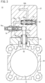
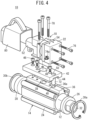
- the high-pressure fluid discharge device 10 includes a tank housing 14 having a tank chamber 12 therein, a diaphragm housing 18 having a diaphragm valve 16 therein, and a control housing 22 having an opening and closing control valve 20 therein.
- the high-pressure fluid discharge device 10 is used for removing cutting chips or the like.
- the tank housing 14 includes a quadrangular tubular cylinder tube 24, a cylindrical inlet cover 26, and a disk-shaped end cover 28.
- the inlet cover 26 is attached to one end side of the cylinder tube 24 via a C-ring 30a, and includes an inlet port 32 penetrating in the axial direction.
- the end cover 28 is attached to the other end side of the cylinder tube 24 via a C-ring 30b, and closes the other end side of the cylinder tube 24.
- the tank chamber 12 that stores high-pressure air (high-pressure fluid) supplied from the inlet port 32 is formed inside the cylinder tube 24.
- a seal member 34a for sealing between the inlet cover 26 and the cylinder tube 24 is attached to the outer peripheral surface of the inlet cover 26.
- a seal member 34b for sealing between the end cover 28 and the cylinder tube 24 is attached to the outer peripheral surface of the end cover 28.
- the upper side wall of the cylinder tube 24 is provided with a pedestal portion 36 projecting upward.
- the pedestal portion 36 extends parallel to the axis of the cylinder tube 24.
- a discharge air supply port 38 penetrates through the upper side wall of the cylinder tube 24, and opens at the top of the pedestal portion 36.
- an operating air supply port 40 for supplying air toward the opening and closing control valve 20 described later penetrates through the upper side wall of the cylinder tube 24.
- the operating air supply port 40 opens in a circular recess 36a formed in the top of the pedestal portion 36.
- a connecting plate 42 for mounting the diaphragm housing 18 and the control housing 22 is arranged on an upper portion of the cylinder tube 24.
- the lower surface of the connecting plate 42 is provided with a recessed groove 44 matching the cross-sectional shape of the pedestal portion 36 of the cylinder tube 24.
- the connecting plate 42 is fixed to the pedestal portion 36 by a plurality of first bolts 46.
- the connecting plate 42 has a first hole 48 penetrating in the vertical direction at a position corresponding to the discharge air supply port 38 of the tank housing 14.
- the first hole 48 includes a lower passage forming portion 48a having a diameter equal to that of the discharge air supply port 38 and an upper fitting portion 48b having a diameter larger than that of the passage forming portion 48a.
- the connecting plate 42 has a second hole 50 penetrating in the vertical direction at a position corresponding to the operating air supply port 40.
- the diaphragm housing 18 is formed by combining a first body 52 and a second body 54.
- the first body 52 and the second body 54 are butted against each other by fitting an annular convex portion 52a provided on the outer peripheral side of the right side surface of the first body 52 into an annular concave portion 54a provided on the outer peripheral side of the left side surface of the second body 54.
- the diaphragm valve 16 has a thick main body portion 16a having a cylindrical shape and a flange 16b that is thinner than the main body portion 16a and is flexible. An outer peripheral edge portion of the flange 16b is sandwiched between the first body 52 and the second body 54.
- the first body 52 has an annular valve chamber 56 defined by the diaphragm valve 16.
- the second body 54 has a pilot chamber 58 defined by the diaphragm valve 16.
- the interior of the main body portion 16a of the diaphragm valve 16 is provided with a pilot passage 16c for allowing the pilot chamber 58 to communicate with the valve chamber 56.
- One end of the pilot passage 16c opens at a side surface of the main body portion 16a that faces the valve chamber 56.
- the other end of the pilot passage 16c opens at an end surface of the main body portion 16a facing the pilot chamber 58.
- the bottom surface of the first body 52 is provided with an annular projecting portion 52b projecting downward at a position corresponding to the discharge air supply port 38 of the tank housing 14.
- the bottom portion of the first body 52 including the projecting portion 52b has a connection passage 59 for connecting the discharge air supply port 38 to the valve chamber 56.
- the projecting portion 52b of the first body 52 is fitted into the fitting portion 48b of the first hole 48 of the connecting plate 42.
- the discharge air supply port 38 communicates with the valve chamber 56 via the passage forming portion 48a of the first hole 48 of the connecting plate 42 and the connection passage 59 of the first body 52.
- Reference numeral 34c denotes a seal member for sealing between the projecting portion 52b and the fitting portion 48b.
- the first body 52 has a discharge port 60 opened on a side surface opposite to a side surface butted against the second body 54, and a discharge passage 62 communicating with the discharge port 60 and extending to the vicinity of the diaphragm valve 16.
- the first body 52 includes therein a tubular wall portion 52c that separates the valve chamber 56 and the discharge passage 62.
- the distal end of the tubular wall portion 52c constitutes a valve seat 52d.
- the control housing 22 has a first release flow path 64a and a second release flow path 64b.
- the first release flow path 64a and the second release flow path 64b form a part of a flow path for releasing the air in the pilot chamber 58 toward the discharge passage 62.
- One end of the first release flow path 64a opens at a side surface of the control housing 22 that faces the diaphragm housing 18, and the one end is connected to an extension passage 58a extending from the pilot chamber 58.
- the other end of the first release flow path 64a is connected to the opening and closing control valve 20.
- Reference numeral 34d denotes a seal member for sealing a connection portion between the first release flow path 64a and the extension passage 58a from the outside.
- the diaphragm housing 18 has a third release flow path 64c and a fourth release flow path 64d.
- the third release flow path 64c and the fourth release flow path 64d constitute the remaining portions of the flow path for releasing the air in the pilot chamber 58 toward the discharge passage 62.
- the third release flow path 64c is formed in the second body 54, and the fourth release flow path 64d is formed in the first body 52.
- One end of the fourth release flow path 64d is connected to the third release flow path 64c, and the other end of the fourth release flow path 64d is connected to the discharge passage 62.
- One end of the second release flow path 64b formed in the control housing 22 is connected to the opening and closing control valve 20.
- the other end of the second release flow path 64b opens at the side surface of the control housing 22 facing the diaphragm housing 18 and is connected to the third release flow path 64c formed in the second body 54.
- the opening and closing control valve 20 includes a spool 66 slidable between a position where the second release flow path 64b is connected to the first release flow path 64a and a position where the second release flow path 64b is blocked from the first release flow path 64a.
- the spool 66 receives the urging force of a spring 68 in one direction and receives the urging force of the air pressure of a second operating air flow path 70b described later in the opposite direction.
- the first release flow path 64a is always connected to a recess 66a formed in the outer peripheral surface of the spool 66.
- the spool 66 moves to the position where the second release flow path 64b is blocked from the first release flow path 64a, by the biasing force of the spring 68 (see FIG. 3 ). At this time, the air in the pilot chamber 58 is confined.
- the spool 66 moves, against the urging force of the spring 68, to the position where the second release flow path 64b is connected to the first release flow path 64a (see FIG. 6 ). At this time, the air in the pilot chamber 58 is released toward the discharge passage 62.
- the control housing 22 has an operating air flow path with a speed controller 74 being installed in the path.
- the operating air flow path includes a first operating air flow path 70a located upstream of the speed controller 74 and the second operating air flow path 70b located downstream of the speed controller 74.
- the first operating air flow path 70a opens in a circular recess 22a formed in the bottom of the control housing 22.
- the second operating air flow path 70b is connected to the opening and closing control valve 20.
- a cylindrical sleeve 72 is inserted into the second hole 50 of the connecting plate 42.
- the sleeve 72 is supported between the circular recess 22a formed in the control housing 22 and the circular recess 36a formed in the pedestal portion 36 of the cylinder tube 24.
- the operating air supply port 40 of the cylinder tube 24 communicates with the first operating air flow path 70a via a passage formed inside the sleeve 72.
- a seal member 34e abutting against the wall surface of the circular recess 22a of the control housing 22 and a seal member 34f abutting against the wall surface of the circular recess 36a of the pedestal portion 36 of the cylinder tube 24 are mounted.
- the speed controller 74 is a variable flow rate control valve capable of adjusting the flow rate of air flowing through the operating air flow path.
- the flow rate of air passing through the speed controller 74 can be adjusted by operating a knob 74a of the speed controller 74 to thereby set a needle 74b provided inside the speed controller 74, to a desired position.
- the flow rate of the air passing through the speed controller 74 determines the rising speed of the pressure of the air in the second operating air flow path 70b acting on the spool 66 of the opening and closing control valve 20 when the air pressure in the tank chamber 12 rises.
- the first body 52, the second body 54, and the control housing 22 are connected in series by a plurality of second bolts 76.
- the first body 52 is connected to the connecting plate 42 by a plurality of third bolts 78.
- the diaphragm housing 18 constituted by the first body 52 and the second body 54 and the control housing 22 are integrally connected to the connecting plate 42.
- Reference numeral 80 denotes a cover body that covers the diaphragm housing 18.
- the high-pressure fluid discharge device 10 is basically configured as described above. Hereinafter, the operation will be described with reference to FIGS. 2 to 7 .
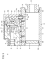
- a state in which the main body portion 16a of the diaphragm valve 16 abuts against the valve seat 52d and the spool 66 of the opening and closing control valve 20 is at a position at which the second release flow path 64b is blocked from the first release flow path 64a is referred to as an initial state. That is, a state in which both the diaphragm valve 16 and the opening and closing control valve 20 are closed is defined as an initial state.
- the high-pressure air is not sufficiently stored in the tank chamber 12, the pressure of the air in the valve chamber 56 and the pilot chamber 58 communicating with each other via the pilot passage 16c is higher than the pressure of the air in the discharge passage 62.
- the pressure of the air in the tank chamber 12 increases. Part of the air enters the valve chamber 56 through the discharge air supply port 38, the passage forming portion 48a of the first hole 48 of the connecting plate 42, and the connection passage 59 of the first body 52, and then enters the pilot chamber 58 through the pilot passage 16c. Therefore, the pressure of the air in the valve chamber 56 and the pilot chamber 58 continues to be higher than the pressure of the air in the discharge passage 62, and the diaphragm valve 16 is kept closed.
- Another part of the air in the tank chamber 12 flows toward the speed controller 74 through the operating air supply port 40, the inside of the sleeve 72, and the first operating air flow path 70a.
- the flow rate of the air passing through the speed controller 74 that is, the flow rate of the air flowing into the second operating air flow path 70b is limited to a flow rate corresponding to the position of the needle 74b of the speed controller 74. Therefore, the pressure of the air in the second operating air flow path 70b acting on the opening and closing control valve 20 increases at a speed corresponding to the limited flow rate.
- the spool 66 of the opening and closing control valve 20 moves against the urging force of the spring 68, and the second release flow path 64b is connected to the first release flow path 64a. That is, the opening and closing control valve 20 is opened (see FIG. 6 ).
- the air in the pilot chamber 58 sequentially flows through the first release flow path 64a to the fourth release flow path 64d and reaches the discharge passage 62.
- the air in the pilot chamber 58 When the air in the pilot chamber 58 is released, the pressure of the air in the pilot chamber 58 decreases, and the main body portion 16a of the diaphragm valve 16 separates from the valve seat 52d. That is, the diaphragm valve 16 opens (see FIG. 5 ). Then, the air supplied to and stored in the tank chamber 12 through the inlet port 32 enters the valve chamber 56 through the discharge air supply port 38, the passage forming portion 48a of the first hole 48 of the connecting plate 42, and the connection passage 59 of the first body 52. Thereafter, the air flows into the discharge passage 62 at once and is discharged from the discharge port 60 to the outside.
- the pressure of the air in the tank chamber 12 decreases, and the pressure of the air in the second operating air flow path 70b acting on the spool 66 of the opening and closing control valve 20 also decreases.
- the pressure of the air in the second operating air flow path 70b becomes lower than the predetermined value.
- the spool 66 is moved by the urging force of the spring 68, and the second release flow path 64b is blocked from the first release flow path 64a. That is, the opening and closing control valve 20 is closed.
- the opening and closing control valve 20 When the opening and closing control valve 20 is closed, the releasing of the air in the pilot chamber 58 is stopped. Further, since the air from the valve chamber 56 flows into the pilot chamber 58 via the pilot passage 16c, the pressure of the air in the pilot chamber 58 increases. On the other hand, since the air in the valve chamber 56 and the discharge passage 62 that communicate with each other is discharged from the discharge port 60 to the outside, the pressure of the air in the pilot chamber 58 becomes higher than the pressure of the air in the valve chamber 56 and the discharge passage 62. As a result, the main body portion 16a of the diaphragm valve 16 comes into contact with the valve seat 52d, and the diaphragm valve 16 is closed. Therefore, the discharge of air from the discharge port 60 is stopped, and the state returns to the initial state.
- FIG. 7 shows how the air pressure in the tank chamber 12 and the air pressure in the discharge port 60 change when the above-described series of operations are periodically repeated.
- the pressure of the air in the tank chamber 12 is indicated by a one dot chain line, and the pressure of the air in the discharge port 60 is indicated by a solid line.
- the discharge pressure in the continuous air blow is indicated by a dotted line.
- the period in this case depends on the air flow rate set by the speed controller 74. Specifically, when the position of the needle 74b is changed by operating the knob 74a of the speed controller 74 and the flow path area around the needle 74b is reduced, the period becomes longer.
- the peak pressure P2 at the discharge port 60 depends on the strength of the spring 68 of the opening and closing control valve 20. The stronger the spring 68 (the greater the spring constant), the greater the peak pressure P2.
- air having a high peak pressure P2 can be periodically discharged from the discharge port 60 merely by continuously supplying high-pressure fluid through the inlet port 32.
- high-pressure air is used as the high-pressure fluid.
- the fluid to be used is not limited to air and may be another fluid as long as it is a compressible fluid.
- the speed controller is provided in the present embodiment, the speed controller need not necessarily be provided when it is not necessary to adjust the period.
- a high-pressure fluid discharge device 90 according to a second embodiment of the present invention will be described with reference to FIGS. 8 and 9 .
- the same or equivalent components as those of the high-pressure fluid discharge device 10 described above are denoted by the same reference numerals, and detailed description thereof will be omitted.
- the high-pressure fluid discharge device 90 is attached to a spindle 82 of a machining center, and is used to remove chips adhering to the surface of the workpiece.
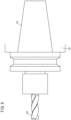
- FIG. 9 shows a state in which an end mill (tool) 84 is mounted on the spindle 82 of the machining center via a tool holder 94.
- the high-pressure fluid discharge device 90 includes a hollow conical tool holder 94 in which a tank chamber 92 is formed, the diaphragm housing 18 incorporating the diaphragm valve 16, and the control housing 22 incorporating the opening and closing control valve 20.
- the tool holder 94 is one of a plurality of tool holders which are attached to the spindle 82 of the machining center.
- the high-pressure fluid discharge device 90 includes, as a part of the configuration, an empty tool holder from among a plurality of tool holders used for mounting a tool such as an end mill in a machining center, and uses the internal space thereof as the tank chamber 92.
- the tool holder 94 includes an inlet port 94a on one end side in the axial direction thereof.
- a plate-shaped cover plate 96 that forms a wall surface of the tank chamber 92 together with an inner wall surface of the tool holder 94 is attached to the other end side of the tool holder 94 in the axial direction.
- a seal member 34g for sealing the tank chamber 92 from the outside is attached to an end surface of the tool holder 94 that contacts the cover plate 96.
- the cover plate 96 has a discharge air supply port 96a and an operating air supply port 96b, which penetrate through a wall surface thereof.
- the diaphragm housing 18 and the control housing 22 are mounted on a surface of the cover plate 96 opposite to a surface against which the tool holder 94 abuts.
- an annular projecting portion 52b projecting rightward is provided at a position corresponding to the discharge air supply port 96a of the cover plate 96.
- the projecting portion 52b is fitted to the cover plate 96.
- the discharge air supply port 96a communicates with the valve chamber 56 via a connection passage 59 provided in the right side surface portion of the first body 52 including the projecting portion 52b.
- a sleeve 72 is disposed between the control housing 22 and the cover plate 96 at a position corresponding to the operating air supply port 96b of the cover plate 96.
- the operating air supply port 96b of the cover plate 96 communicates with the first operating air flow path 70a of the control housing 22 via a passage inside the sleeve 72.
- the first body 52 has a discharge port 60 opened on the left side surface of the first body 52 and a discharge passage 62 communicating with the discharge port 60 and extending to the vicinity of the diaphragm valve 16.
- the discharge port 60 and the discharge passage 62 extend parallel to the axial direction of the tool holder 94.
- the control housing 22 includes a first release flow path 64a and a second release flow path 64b as flow paths for releasing the air in the pilot chamber 58 toward the discharge passage 62.
- the diaphragm housing 18 includes a third release flow path 64c and a fourth release flow path 64d.
- the third release flow path 64c and the fourth release flow path 64d are arranged in one straight line and extend in a direction perpendicular to the discharge passage 62.
- the high-pressure fluid discharge device 90 of the present embodiment includes, as a part of the configuration, the tool holder 94 attached to the spindle 82 of the machining center, and uses the internal space thereof as the tank chamber 92, and thus attachment to the machining center is easy and the configuration is simplified as much as possible.
- the tool holder is a standardized member, and accordingly the high-pressure fluid discharge device 90 of the same specification can be applied to various machining centers.
Landscapes
- Engineering & Computer Science (AREA)
- General Engineering & Computer Science (AREA)
- Mechanical Engineering (AREA)
- Physics & Mathematics (AREA)
- Fluid Mechanics (AREA)
- Chemical & Material Sciences (AREA)
- Analytical Chemistry (AREA)
- Fluid-Driven Valves (AREA)
- Nozzles (AREA)
- Reciprocating Pumps (AREA)
Applications Claiming Priority (3)
| Application Number | Priority Date | Filing Date | Title |
|---|---|---|---|
| JP2019079011 | 2019-04-18 | ||
| JP2019198077 | 2019-10-31 | ||
| PCT/JP2020/005987 WO2020213248A1 (ja) | 2019-04-18 | 2020-02-17 | 高圧流体吐出装置 |
Publications (3)
| Publication Number | Publication Date |
|---|---|
| EP3957402A1 EP3957402A1 (en) | 2022-02-23 |
| EP3957402A4 EP3957402A4 (en) | 2023-01-18 |
| EP3957402B1 true EP3957402B1 (en) | 2025-01-22 |
Family
ID=72838189
Family Applications (1)
| Application Number | Title | Priority Date | Filing Date |
|---|---|---|---|
| EP20791581.0A Active EP3957402B1 (en) | 2019-04-18 | 2020-02-17 | High-pressure fluid discharge device |
Country Status (7)
| Country | Link |
|---|---|
| US (1) | US12305674B2 (https=) |
| EP (1) | EP3957402B1 (https=) |
| JP (1) | JP7537428B2 (https=) |
| KR (1) | KR102729053B1 (https=) |
| CN (1) | CN113710369B (https=) |
| TW (1) | TWI743737B (https=) |
| WO (1) | WO2020213248A1 (https=) |
Families Citing this family (1)
| Publication number | Priority date | Publication date | Assignee | Title |
|---|---|---|---|---|
| CN113984485A (zh) * | 2021-09-30 | 2022-01-28 | 深圳中科飞测科技股份有限公司 | 清洁方法及相关装置 |
Family Cites Families (26)
| Publication number | Priority date | Publication date | Assignee | Title |
|---|---|---|---|---|
| US4284260A (en) * | 1977-09-15 | 1981-08-18 | Nicolas Baranoff | Automatic discharge valve for liquids |
| GB2091451B (en) * | 1981-01-07 | 1985-04-17 | Reed Irrigation Systems | Filter backwash means |
| JPS60186875U (ja) * | 1984-05-22 | 1985-12-11 | 富士化工株式会社 | 電刷子 |
| JPH03624Y2 (https=) * | 1985-05-13 | 1991-01-10 | ||
| JP2554561B2 (ja) * | 1991-04-25 | 1996-11-13 | 株式会社ヨシタケ | パイロット型電磁弁 |
| US5169117A (en) * | 1992-02-27 | 1992-12-08 | Huang Chi King | Low power type, motor-controlled magnetic valve |
| JPH08128389A (ja) * | 1994-11-01 | 1996-05-21 | Hitachi Ltd | バルブ駆動制御方法およびバルブ駆動制御装置ならびに流動体供給制御装置 |
| DE29705703U1 (de) * | 1996-06-03 | 1997-05-22 | Geberit Technik Ag, Jona | Servogesteuertes Wasserventil |
| JPH10165844A (ja) * | 1996-12-12 | 1998-06-23 | Ckd Corp | エア噴射システム |
| AUPO524997A0 (en) * | 1997-02-21 | 1997-03-20 | Yoothapina Pty Ltd | Filling stop valve |
| JP3329720B2 (ja) * | 1998-01-19 | 2002-09-30 | 東京エレクトロン株式会社 | 塗布装置 |
| JP3549501B2 (ja) * | 2001-07-23 | 2004-08-04 | カネキタ株式会社 | エアパルサおよびそのエアパルサを利用する装置 |
| US6780170B2 (en) * | 2002-05-15 | 2004-08-24 | Liebel-Flarsheim Company | Hydraulic remote for a medical fluid injector |
| JP3875959B2 (ja) * | 2003-03-27 | 2007-01-31 | 泰彦 渡辺 | 流量制御弁 |
| US7080817B2 (en) * | 2004-02-17 | 2006-07-25 | Y. Stern Engineering (1989) Ltd. | Electromagnetic valve |
| JP2005291493A (ja) | 2004-03-11 | 2005-10-20 | Kanekita Kk | エアパルサ |
| JP2008513200A (ja) * | 2004-09-15 | 2008-05-01 | アクリオン テクノロジーズ インク | 音波エネルギ源を動かす装置及び方法、及びそれを用いた基板の処理 |
| US7647941B2 (en) * | 2006-04-03 | 2010-01-19 | Masao Onoe | Air pulser |
| BRPI0807862B8 (pt) * | 2007-01-24 | 2023-01-31 | I2O Water Ltd | Controlador e sistema de controle para uma válvula redutora de pressão |
| JP2009275747A (ja) * | 2008-05-13 | 2009-11-26 | Nippon Spindle Mfg Co Ltd | ダイヤフラムバルブ及び集塵機 |
| JP5728288B2 (ja) | 2011-04-28 | 2015-06-03 | Ckd株式会社 | 給排気調整装置、給排気調整システム |
| JP5551224B2 (ja) | 2012-10-26 | 2014-07-16 | 本田技研工業株式会社 | 間欠エアブローガン |
| JP6047796B2 (ja) * | 2015-03-03 | 2016-12-21 | 有限会社浜インターナショナル | スピードコントローラ |
| JP6230517B2 (ja) | 2014-10-08 | 2017-11-15 | クロダニューマティクス株式会社 | 間歇エア発生装置 |
| KR200480920Y1 (ko) * | 2014-12-19 | 2016-07-22 | 김성곤 | 분사밸브, 분사밸브 배출 장비 및 분사 장비 유닛 |
| JP6591686B2 (ja) * | 2016-08-29 | 2019-10-16 | 株式会社コガネイ | 切換弁および間欠エアブローガン |
-
2020
- 2020-02-17 US US17/603,375 patent/US12305674B2/en active Active
- 2020-02-17 WO PCT/JP2020/005987 patent/WO2020213248A1/ja not_active Ceased
- 2020-02-17 JP JP2021514808A patent/JP7537428B2/ja active Active
- 2020-02-17 EP EP20791581.0A patent/EP3957402B1/en active Active
- 2020-02-17 CN CN202080029559.0A patent/CN113710369B/zh active Active
- 2020-02-17 KR KR1020217036901A patent/KR102729053B1/ko active Active
- 2020-04-09 TW TW109111987A patent/TWI743737B/zh active
Also Published As
| Publication number | Publication date |
|---|---|
| JPWO2020213248A1 (https=) | 2020-10-22 |
| KR102729053B1 (ko) | 2024-11-13 |
| CN113710369B (zh) | 2022-11-25 |
| EP3957402A1 (en) | 2022-02-23 |
| US20220205467A1 (en) | 2022-06-30 |
| KR20210149174A (ko) | 2021-12-08 |
| TW202042912A (zh) | 2020-12-01 |
| US12305674B2 (en) | 2025-05-20 |
| TWI743737B (zh) | 2021-10-21 |
| JP7537428B2 (ja) | 2024-08-21 |
| EP3957402A4 (en) | 2023-01-18 |
| WO2020213248A1 (ja) | 2020-10-22 |
| CN113710369A (zh) | 2021-11-26 |
Similar Documents
| Publication | Publication Date | Title |
|---|---|---|
| EP1384513B1 (en) | Droplets forming method and device for discharging constant-volume droplets | |
| KR102363630B1 (ko) | 압축유체 토출 제어장치 | |
| WO2011162270A2 (en) | Pressure reducing apparatus | |
| US20050118032A1 (en) | Vaccum-generating unit | |
| EP3957402B1 (en) | High-pressure fluid discharge device | |
| JP2009036096A (ja) | 真空発生ユニット | |
| EP4040023B1 (en) | High-pressure fluid discharge device | |
| KR102508110B1 (ko) | 압축유체 토출 제어장치 | |
| KR20190088014A (ko) | 역지 밸브 | |
| WO2000066321A1 (fr) | Dispositif d'alimentation en fluide de refroidissement d'une machine-outil | |
| JP4377990B2 (ja) | 高圧クーラントバルブ | |
| KR20190056441A (ko) | 간헐적 에어 발생장치 | |
| JP2605802Y2 (ja) | スピードコントローラ | |
| CN115234684A (zh) | 脉冲空气发生装置 | |
| JP4204513B2 (ja) | 加工装置 | |
| JP4162627B2 (ja) | セミドライ加工装置 | |
| JP2005329487A (ja) | 加工装置 | |
| JPS63185545A (ja) | 磁気チヤツクにおける流体噴出部の塵埃除去方法 | |
| JP2011189256A (ja) | 塗料充填装置 |
Legal Events
| Date | Code | Title | Description |
|---|---|---|---|
| STAA | Information on the status of an ep patent application or granted ep patent |
Free format text: STATUS: THE INTERNATIONAL PUBLICATION HAS BEEN MADE |
|
| PUAI | Public reference made under article 153(3) epc to a published international application that has entered the european phase |
Free format text: ORIGINAL CODE: 0009012 |
|
| STAA | Information on the status of an ep patent application or granted ep patent |
Free format text: STATUS: REQUEST FOR EXAMINATION WAS MADE |
|
| 17P | Request for examination filed |
Effective date: 20211020 |
|
| AK | Designated contracting states |
Kind code of ref document: A1 Designated state(s): AL AT BE BG CH CY CZ DE DK EE ES FI FR GB GR HR HU IE IS IT LI LT LU LV MC MK MT NL NO PL PT RO RS SE SI SK SM TR |
|
| DAV | Request for validation of the european patent (deleted) | ||
| DAX | Request for extension of the european patent (deleted) | ||
| RIN1 | Information on inventor provided before grant (corrected) |
Inventor name: SASAKI, HIROAKI Inventor name: OSHIMA, MASAYUKI Inventor name: DOI, YOSHITADA |
|
| A4 | Supplementary search report drawn up and despatched |
Effective date: 20221219 |
|
| RIC1 | Information provided on ipc code assigned before grant |
Ipc: F15B 21/12 20060101ALI20221213BHEP Ipc: B05B 12/06 20060101ALI20221213BHEP Ipc: B05B 1/00 20060101ALI20221213BHEP Ipc: F16K 31/385 20060101AFI20221213BHEP |
|
| REG | Reference to a national code |
Ref country code: DE Free format text: PREVIOUS MAIN CLASS: B05B0009030000 Ref legal event code: R079 Ref document number: 602020045221 Country of ref document: DE Ipc: F16K0031385000 |
|
| GRAP | Despatch of communication of intention to grant a patent |
Free format text: ORIGINAL CODE: EPIDOSNIGR1 |
|
| STAA | Information on the status of an ep patent application or granted ep patent |
Free format text: STATUS: GRANT OF PATENT IS INTENDED |
|
| RIC1 | Information provided on ipc code assigned before grant |
Ipc: F15B 21/12 20060101ALI20240710BHEP Ipc: F16K 7/17 20060101ALI20240710BHEP Ipc: B05B 12/06 20060101ALI20240710BHEP Ipc: B08B 5/02 20060101ALI20240710BHEP Ipc: B05B 1/00 20060101ALI20240710BHEP Ipc: F16K 31/385 20060101AFI20240710BHEP |
|
| INTG | Intention to grant announced |
Effective date: 20240812 |
|
| GRAS | Grant fee paid |
Free format text: ORIGINAL CODE: EPIDOSNIGR3 |
|
| GRAA | (expected) grant |
Free format text: ORIGINAL CODE: 0009210 |
|
| STAA | Information on the status of an ep patent application or granted ep patent |
Free format text: STATUS: THE PATENT HAS BEEN GRANTED |
|
| AK | Designated contracting states |
Kind code of ref document: B1 Designated state(s): AL AT BE BG CH CY CZ DE DK EE ES FI FR GB GR HR HU IE IS IT LI LT LU LV MC MK MT NL NO PL PT RO RS SE SI SK SM TR |
|
| REG | Reference to a national code |
Ref country code: GB Ref legal event code: FG4D |
|
| REG | Reference to a national code |
Ref country code: CH Ref legal event code: EP |
|
| REG | Reference to a national code |
Ref country code: IE Ref legal event code: FG4D |
|
| REG | Reference to a national code |
Ref country code: DE Ref legal event code: R096 Ref document number: 602020045221 Country of ref document: DE |
|
| REG | Reference to a national code |
Ref country code: NL Ref legal event code: MP Effective date: 20250122 |
|
| RAP4 | Party data changed (patent owner data changed or rights of a patent transferred) |
Owner name: SMC CORPORATION |
|
| PG25 | Lapsed in a contracting state [announced via postgrant information from national office to epo] |
Ref country code: NL Free format text: LAPSE BECAUSE OF FAILURE TO SUBMIT A TRANSLATION OF THE DESCRIPTION OR TO PAY THE FEE WITHIN THE PRESCRIBED TIME-LIMIT Effective date: 20250122 |
|
| PG25 | Lapsed in a contracting state [announced via postgrant information from national office to epo] |
Ref country code: RS Free format text: LAPSE BECAUSE OF FAILURE TO SUBMIT A TRANSLATION OF THE DESCRIPTION OR TO PAY THE FEE WITHIN THE PRESCRIBED TIME-LIMIT Effective date: 20250422 |
|
| PG25 | Lapsed in a contracting state [announced via postgrant information from national office to epo] |
Ref country code: FI Free format text: LAPSE BECAUSE OF FAILURE TO SUBMIT A TRANSLATION OF THE DESCRIPTION OR TO PAY THE FEE WITHIN THE PRESCRIBED TIME-LIMIT Effective date: 20250122 |
|
| PG25 | Lapsed in a contracting state [announced via postgrant information from national office to epo] |
Ref country code: PL Free format text: LAPSE BECAUSE OF FAILURE TO SUBMIT A TRANSLATION OF THE DESCRIPTION OR TO PAY THE FEE WITHIN THE PRESCRIBED TIME-LIMIT Effective date: 20250122 |
|
| PG25 | Lapsed in a contracting state [announced via postgrant information from national office to epo] |
Ref country code: ES Free format text: LAPSE BECAUSE OF FAILURE TO SUBMIT A TRANSLATION OF THE DESCRIPTION OR TO PAY THE FEE WITHIN THE PRESCRIBED TIME-LIMIT Effective date: 20250122 |
|
| REG | Reference to a national code |
Ref country code: LT Ref legal event code: MG9D |
|
| PG25 | Lapsed in a contracting state [announced via postgrant information from national office to epo] |
Ref country code: NO Free format text: LAPSE BECAUSE OF FAILURE TO SUBMIT A TRANSLATION OF THE DESCRIPTION OR TO PAY THE FEE WITHIN THE PRESCRIBED TIME-LIMIT Effective date: 20250422 Ref country code: IS Free format text: LAPSE BECAUSE OF FAILURE TO SUBMIT A TRANSLATION OF THE DESCRIPTION OR TO PAY THE FEE WITHIN THE PRESCRIBED TIME-LIMIT Effective date: 20250522 |
|
| REG | Reference to a national code |
Ref country code: AT Ref legal event code: MK05 Ref document number: 1761690 Country of ref document: AT Kind code of ref document: T Effective date: 20250122 |
|
| PG25 | Lapsed in a contracting state [announced via postgrant information from national office to epo] |
Ref country code: HR Free format text: LAPSE BECAUSE OF FAILURE TO SUBMIT A TRANSLATION OF THE DESCRIPTION OR TO PAY THE FEE WITHIN THE PRESCRIBED TIME-LIMIT Effective date: 20250122 |
|
| PG25 | Lapsed in a contracting state [announced via postgrant information from national office to epo] |
Ref country code: PT Free format text: LAPSE BECAUSE OF FAILURE TO SUBMIT A TRANSLATION OF THE DESCRIPTION OR TO PAY THE FEE WITHIN THE PRESCRIBED TIME-LIMIT Effective date: 20250522 Ref country code: LV Free format text: LAPSE BECAUSE OF FAILURE TO SUBMIT A TRANSLATION OF THE DESCRIPTION OR TO PAY THE FEE WITHIN THE PRESCRIBED TIME-LIMIT Effective date: 20250122 |
|
| PG25 | Lapsed in a contracting state [announced via postgrant information from national office to epo] |
Ref country code: GR Free format text: LAPSE BECAUSE OF FAILURE TO SUBMIT A TRANSLATION OF THE DESCRIPTION OR TO PAY THE FEE WITHIN THE PRESCRIBED TIME-LIMIT Effective date: 20250423 Ref country code: BG Free format text: LAPSE BECAUSE OF FAILURE TO SUBMIT A TRANSLATION OF THE DESCRIPTION OR TO PAY THE FEE WITHIN THE PRESCRIBED TIME-LIMIT Effective date: 20250122 |
|
| PG25 | Lapsed in a contracting state [announced via postgrant information from national office to epo] |
Ref country code: AT Free format text: LAPSE BECAUSE OF FAILURE TO SUBMIT A TRANSLATION OF THE DESCRIPTION OR TO PAY THE FEE WITHIN THE PRESCRIBED TIME-LIMIT Effective date: 20250122 |
|
| PG25 | Lapsed in a contracting state [announced via postgrant information from national office to epo] |
Ref country code: SE Free format text: LAPSE BECAUSE OF FAILURE TO SUBMIT A TRANSLATION OF THE DESCRIPTION OR TO PAY THE FEE WITHIN THE PRESCRIBED TIME-LIMIT Effective date: 20250122 |
|
| REG | Reference to a national code |
Ref country code: CH Ref legal event code: PL |
|
| PG25 | Lapsed in a contracting state [announced via postgrant information from national office to epo] |
Ref country code: SM Free format text: LAPSE BECAUSE OF FAILURE TO SUBMIT A TRANSLATION OF THE DESCRIPTION OR TO PAY THE FEE WITHIN THE PRESCRIBED TIME-LIMIT Effective date: 20250122 |
|
| PG25 | Lapsed in a contracting state [announced via postgrant information from national office to epo] |
Ref country code: DK Free format text: LAPSE BECAUSE OF FAILURE TO SUBMIT A TRANSLATION OF THE DESCRIPTION OR TO PAY THE FEE WITHIN THE PRESCRIBED TIME-LIMIT Effective date: 20250122 |
|
| PG25 | Lapsed in a contracting state [announced via postgrant information from national office to epo] |
Ref country code: MC Free format text: LAPSE BECAUSE OF FAILURE TO SUBMIT A TRANSLATION OF THE DESCRIPTION OR TO PAY THE FEE WITHIN THE PRESCRIBED TIME-LIMIT Effective date: 20250122 |
|
| PG25 | Lapsed in a contracting state [announced via postgrant information from national office to epo] |
Ref country code: IT Free format text: LAPSE BECAUSE OF FAILURE TO SUBMIT A TRANSLATION OF THE DESCRIPTION OR TO PAY THE FEE WITHIN THE PRESCRIBED TIME-LIMIT Effective date: 20250122 Ref country code: LU Free format text: LAPSE BECAUSE OF NON-PAYMENT OF DUE FEES Effective date: 20250217 |
|
| PG25 | Lapsed in a contracting state [announced via postgrant information from national office to epo] |
Ref country code: CH Free format text: LAPSE BECAUSE OF NON-PAYMENT OF DUE FEES Effective date: 20250228 |
|
| PG25 | Lapsed in a contracting state [announced via postgrant information from national office to epo] |
Ref country code: EE Free format text: LAPSE BECAUSE OF FAILURE TO SUBMIT A TRANSLATION OF THE DESCRIPTION OR TO PAY THE FEE WITHIN THE PRESCRIBED TIME-LIMIT Effective date: 20250122 Ref country code: CZ Free format text: LAPSE BECAUSE OF FAILURE TO SUBMIT A TRANSLATION OF THE DESCRIPTION OR TO PAY THE FEE WITHIN THE PRESCRIBED TIME-LIMIT Effective date: 20250122 |
|
| REG | Reference to a national code |
Ref country code: DE Ref legal event code: R097 Ref document number: 602020045221 Country of ref document: DE |
|
| PG25 | Lapsed in a contracting state [announced via postgrant information from national office to epo] |
Ref country code: RO Free format text: LAPSE BECAUSE OF FAILURE TO SUBMIT A TRANSLATION OF THE DESCRIPTION OR TO PAY THE FEE WITHIN THE PRESCRIBED TIME-LIMIT Effective date: 20250122 |
|
| PG25 | Lapsed in a contracting state [announced via postgrant information from national office to epo] |
Ref country code: SK Free format text: LAPSE BECAUSE OF FAILURE TO SUBMIT A TRANSLATION OF THE DESCRIPTION OR TO PAY THE FEE WITHIN THE PRESCRIBED TIME-LIMIT Effective date: 20250122 |
|
| PLBE | No opposition filed within time limit |
Free format text: ORIGINAL CODE: 0009261 |
|
| STAA | Information on the status of an ep patent application or granted ep patent |
Free format text: STATUS: NO OPPOSITION FILED WITHIN TIME LIMIT |
|
| REG | Reference to a national code |
Ref country code: BE Ref legal event code: MM Effective date: 20250228 |
|
| GBPC | Gb: european patent ceased through non-payment of renewal fee |
Effective date: 20250422 |
|
| 26N | No opposition filed |
Effective date: 20251023 |
|
| PG25 | Lapsed in a contracting state [announced via postgrant information from national office to epo] |
Ref country code: GB Free format text: LAPSE BECAUSE OF NON-PAYMENT OF DUE FEES Effective date: 20250422 |
|
| PG25 | Lapsed in a contracting state [announced via postgrant information from national office to epo] |
Ref country code: FR Free format text: LAPSE BECAUSE OF NON-PAYMENT OF DUE FEES Effective date: 20250322 |
|
| PG25 | Lapsed in a contracting state [announced via postgrant information from national office to epo] |
Ref country code: BE Free format text: LAPSE BECAUSE OF NON-PAYMENT OF DUE FEES Effective date: 20250228 |
|
| PG25 | Lapsed in a contracting state [announced via postgrant information from national office to epo] |
Ref country code: IE Free format text: LAPSE BECAUSE OF NON-PAYMENT OF DUE FEES Effective date: 20250217 |
|
| PGFP | Annual fee paid to national office [announced via postgrant information from national office to epo] |
Ref country code: DE Payment date: 20260319 Year of fee payment: 7 |