EP3954921B1 - Dispositif de frein à disque - Google Patents
Dispositif de frein à disque Download PDFInfo
- Publication number
- EP3954921B1 EP3954921B1 EP21189868.9A EP21189868A EP3954921B1 EP 3954921 B1 EP3954921 B1 EP 3954921B1 EP 21189868 A EP21189868 A EP 21189868A EP 3954921 B1 EP3954921 B1 EP 3954921B1
- Authority
- EP
- European Patent Office
- Prior art keywords
- pad
- circumferential
- brake device
- clip
- disc brake
- Prior art date
- Legal status (The legal status is an assumption and is not a legal conclusion. Google has not performed a legal analysis and makes no representation as to the accuracy of the status listed.)
- Active
Links
- 238000003825 pressing Methods 0.000 claims description 111
- 238000003780 insertion Methods 0.000 claims description 68
- 230000037431 insertion Effects 0.000 claims description 68
- 239000000758 substrate Substances 0.000 claims description 36
- 230000002093 peripheral effect Effects 0.000 claims description 19
- 229910052751 metal Inorganic materials 0.000 claims description 8
- 239000002184 metal Substances 0.000 claims description 8
- 230000007423 decrease Effects 0.000 claims description 4
- 230000005540 biological transmission Effects 0.000 description 46
- 230000008878 coupling Effects 0.000 description 28
- 238000010168 coupling process Methods 0.000 description 28
- 238000005859 coupling reaction Methods 0.000 description 28
- 230000002159 abnormal effect Effects 0.000 description 4
- 230000000694 effects Effects 0.000 description 4
- 239000012530 fluid Substances 0.000 description 4
- 230000000149 penetrating effect Effects 0.000 description 3
- XEEYBQQBJWHFJM-UHFFFAOYSA-N Iron Chemical compound [Fe] XEEYBQQBJWHFJM-UHFFFAOYSA-N 0.000 description 2
- 210000000078 claw Anatomy 0.000 description 2
- 238000004519 manufacturing process Methods 0.000 description 2
- 230000007935 neutral effect Effects 0.000 description 2
- 229910000838 Al alloy Inorganic materials 0.000 description 1
- 229910045601 alloy Inorganic materials 0.000 description 1
- 239000000956 alloy Substances 0.000 description 1
- 238000005266 casting Methods 0.000 description 1
- 238000006243 chemical reaction Methods 0.000 description 1
- 238000005260 corrosion Methods 0.000 description 1
- 230000007797 corrosion Effects 0.000 description 1
- 230000001419 dependent effect Effects 0.000 description 1
- 239000002783 friction material Substances 0.000 description 1
- 229910052742 iron Inorganic materials 0.000 description 1
- 229910001234 light alloy Inorganic materials 0.000 description 1
- 239000000463 material Substances 0.000 description 1
- 238000000034 method Methods 0.000 description 1
- 230000004048 modification Effects 0.000 description 1
- 238000012986 modification Methods 0.000 description 1
- 230000015541 sensory perception of touch Effects 0.000 description 1
- 239000010935 stainless steel Substances 0.000 description 1
- 229910001220 stainless steel Inorganic materials 0.000 description 1
- 239000000725 suspension Substances 0.000 description 1
Images


Classifications
-
- F—MECHANICAL ENGINEERING; LIGHTING; HEATING; WEAPONS; BLASTING
- F16—ENGINEERING ELEMENTS AND UNITS; GENERAL MEASURES FOR PRODUCING AND MAINTAINING EFFECTIVE FUNCTIONING OF MACHINES OR INSTALLATIONS; THERMAL INSULATION IN GENERAL
- F16D—COUPLINGS FOR TRANSMITTING ROTATION; CLUTCHES; BRAKES
- F16D65/00—Parts or details
- F16D65/02—Braking members; Mounting thereof
- F16D65/04—Bands, shoes or pads; Pivots or supporting members therefor
- F16D65/092—Bands, shoes or pads; Pivots or supporting members therefor for axially-engaging brakes, e.g. disc brakes
- F16D65/095—Pivots or supporting members therefor
- F16D65/097—Resilient means interposed between pads and supporting members or other brake parts
- F16D65/0973—Resilient means interposed between pads and supporting members or other brake parts not subjected to brake forces
- F16D65/0974—Resilient means interposed between pads and supporting members or other brake parts not subjected to brake forces acting on or in the vicinity of the pad rim in a direction substantially transverse to the brake disc axis
- F16D65/0977—Springs made from sheet metal
-
- F—MECHANICAL ENGINEERING; LIGHTING; HEATING; WEAPONS; BLASTING
- F16—ENGINEERING ELEMENTS AND UNITS; GENERAL MEASURES FOR PRODUCING AND MAINTAINING EFFECTIVE FUNCTIONING OF MACHINES OR INSTALLATIONS; THERMAL INSULATION IN GENERAL
- F16D—COUPLINGS FOR TRANSMITTING ROTATION; CLUTCHES; BRAKES
- F16D65/00—Parts or details
- F16D65/0006—Noise or vibration control
-
- F—MECHANICAL ENGINEERING; LIGHTING; HEATING; WEAPONS; BLASTING
- F16—ENGINEERING ELEMENTS AND UNITS; GENERAL MEASURES FOR PRODUCING AND MAINTAINING EFFECTIVE FUNCTIONING OF MACHINES OR INSTALLATIONS; THERMAL INSULATION IN GENERAL
- F16D—COUPLINGS FOR TRANSMITTING ROTATION; CLUTCHES; BRAKES
- F16D65/00—Parts or details
- F16D65/02—Braking members; Mounting thereof
- F16D65/04—Bands, shoes or pads; Pivots or supporting members therefor
- F16D65/092—Bands, shoes or pads; Pivots or supporting members therefor for axially-engaging brakes, e.g. disc brakes
-
- B—PERFORMING OPERATIONS; TRANSPORTING
- B60—VEHICLES IN GENERAL
- B60T—VEHICLE BRAKE CONTROL SYSTEMS OR PARTS THEREOF; BRAKE CONTROL SYSTEMS OR PARTS THEREOF, IN GENERAL; ARRANGEMENT OF BRAKING ELEMENTS ON VEHICLES IN GENERAL; PORTABLE DEVICES FOR PREVENTING UNWANTED MOVEMENT OF VEHICLES; VEHICLE MODIFICATIONS TO FACILITATE COOLING OF BRAKES
- B60T1/00—Arrangements of braking elements, i.e. of those parts where braking effect occurs specially for vehicles
- B60T1/02—Arrangements of braking elements, i.e. of those parts where braking effect occurs specially for vehicles acting by retarding wheels
- B60T1/06—Arrangements of braking elements, i.e. of those parts where braking effect occurs specially for vehicles acting by retarding wheels acting otherwise than on tread, e.g. employing rim, drum, disc, or transmission or on double wheels
- B60T1/065—Arrangements of braking elements, i.e. of those parts where braking effect occurs specially for vehicles acting by retarding wheels acting otherwise than on tread, e.g. employing rim, drum, disc, or transmission or on double wheels employing disc
-
- F—MECHANICAL ENGINEERING; LIGHTING; HEATING; WEAPONS; BLASTING
- F16—ENGINEERING ELEMENTS AND UNITS; GENERAL MEASURES FOR PRODUCING AND MAINTAINING EFFECTIVE FUNCTIONING OF MACHINES OR INSTALLATIONS; THERMAL INSULATION IN GENERAL
- F16D—COUPLINGS FOR TRANSMITTING ROTATION; CLUTCHES; BRAKES
- F16D55/00—Brakes with substantially-radial braking surfaces pressed together in axial direction, e.g. disc brakes
- F16D55/02—Brakes with substantially-radial braking surfaces pressed together in axial direction, e.g. disc brakes with axially-movable discs or pads pressed against axially-located rotating members
- F16D55/22—Brakes with substantially-radial braking surfaces pressed together in axial direction, e.g. disc brakes with axially-movable discs or pads pressed against axially-located rotating members by clamping an axially-located rotating disc between movable braking members, e.g. movable brake discs or brake pads
- F16D55/224—Brakes with substantially-radial braking surfaces pressed together in axial direction, e.g. disc brakes with axially-movable discs or pads pressed against axially-located rotating members by clamping an axially-located rotating disc between movable braking members, e.g. movable brake discs or brake pads with a common actuating member for the braking members
- F16D55/225—Brakes with substantially-radial braking surfaces pressed together in axial direction, e.g. disc brakes with axially-movable discs or pads pressed against axially-located rotating members by clamping an axially-located rotating disc between movable braking members, e.g. movable brake discs or brake pads with a common actuating member for the braking members the braking members being brake pads
- F16D55/226—Brakes with substantially-radial braking surfaces pressed together in axial direction, e.g. disc brakes with axially-movable discs or pads pressed against axially-located rotating members by clamping an axially-located rotating disc between movable braking members, e.g. movable brake discs or brake pads with a common actuating member for the braking members the braking members being brake pads in which the common actuating member is moved axially, e.g. floating caliper disc brakes
- F16D55/2265—Brakes with substantially-radial braking surfaces pressed together in axial direction, e.g. disc brakes with axially-movable discs or pads pressed against axially-located rotating members by clamping an axially-located rotating disc between movable braking members, e.g. movable brake discs or brake pads with a common actuating member for the braking members the braking members being brake pads in which the common actuating member is moved axially, e.g. floating caliper disc brakes the axial movement being guided by one or more pins engaging bores in the brake support or the brake housing
- F16D55/227—Brakes with substantially-radial braking surfaces pressed together in axial direction, e.g. disc brakes with axially-movable discs or pads pressed against axially-located rotating members by clamping an axially-located rotating disc between movable braking members, e.g. movable brake discs or brake pads with a common actuating member for the braking members the braking members being brake pads in which the common actuating member is moved axially, e.g. floating caliper disc brakes the axial movement being guided by one or more pins engaging bores in the brake support or the brake housing by two or more pins
-
- F—MECHANICAL ENGINEERING; LIGHTING; HEATING; WEAPONS; BLASTING
- F16—ENGINEERING ELEMENTS AND UNITS; GENERAL MEASURES FOR PRODUCING AND MAINTAINING EFFECTIVE FUNCTIONING OF MACHINES OR INSTALLATIONS; THERMAL INSULATION IN GENERAL
- F16D—COUPLINGS FOR TRANSMITTING ROTATION; CLUTCHES; BRAKES
- F16D65/00—Parts or details
- F16D65/02—Braking members; Mounting thereof
- F16D65/04—Bands, shoes or pads; Pivots or supporting members therefor
- F16D65/092—Bands, shoes or pads; Pivots or supporting members therefor for axially-engaging brakes, e.g. disc brakes
- F16D65/095—Pivots or supporting members therefor
-
- F—MECHANICAL ENGINEERING; LIGHTING; HEATING; WEAPONS; BLASTING
- F16—ENGINEERING ELEMENTS AND UNITS; GENERAL MEASURES FOR PRODUCING AND MAINTAINING EFFECTIVE FUNCTIONING OF MACHINES OR INSTALLATIONS; THERMAL INSULATION IN GENERAL
- F16D—COUPLINGS FOR TRANSMITTING ROTATION; CLUTCHES; BRAKES
- F16D55/00—Brakes with substantially-radial braking surfaces pressed together in axial direction, e.g. disc brakes
- F16D2055/0004—Parts or details of disc brakes
- F16D2055/007—Pins holding the braking members
-
- F—MECHANICAL ENGINEERING; LIGHTING; HEATING; WEAPONS; BLASTING
- F16—ENGINEERING ELEMENTS AND UNITS; GENERAL MEASURES FOR PRODUCING AND MAINTAINING EFFECTIVE FUNCTIONING OF MACHINES OR INSTALLATIONS; THERMAL INSULATION IN GENERAL
- F16D—COUPLINGS FOR TRANSMITTING ROTATION; CLUTCHES; BRAKES
- F16D55/00—Brakes with substantially-radial braking surfaces pressed together in axial direction, e.g. disc brakes
- F16D55/02—Brakes with substantially-radial braking surfaces pressed together in axial direction, e.g. disc brakes with axially-movable discs or pads pressed against axially-located rotating members
- F16D55/22—Brakes with substantially-radial braking surfaces pressed together in axial direction, e.g. disc brakes with axially-movable discs or pads pressed against axially-located rotating members by clamping an axially-located rotating disc between movable braking members, e.g. movable brake discs or brake pads
- F16D55/228—Brakes with substantially-radial braking surfaces pressed together in axial direction, e.g. disc brakes with axially-movable discs or pads pressed against axially-located rotating members by clamping an axially-located rotating disc between movable braking members, e.g. movable brake discs or brake pads with a separate actuating member for each side
-
- F—MECHANICAL ENGINEERING; LIGHTING; HEATING; WEAPONS; BLASTING
- F16—ENGINEERING ELEMENTS AND UNITS; GENERAL MEASURES FOR PRODUCING AND MAINTAINING EFFECTIVE FUNCTIONING OF MACHINES OR INSTALLATIONS; THERMAL INSULATION IN GENERAL
- F16D—COUPLINGS FOR TRANSMITTING ROTATION; CLUTCHES; BRAKES
- F16D65/00—Parts or details
- F16D65/005—Components of axially engaging brakes not otherwise provided for
- F16D65/0087—Brake housing guide members, e.g. caliper pins; Accessories therefor, e.g. dust boots
Definitions
- the present invention relates to a disc brake device.
- a disc brake device obtains a braking force by pressing a pad, which is supported by a pad support member so as to be movable in an axial direction, against a side surface of a rotor in the axial direction.
- various structures have been proposed in related-art as a pad support structure for supporting the pad so as to be movable in the axial direction with respect to the pad support member.
- Figs. 19 and 20 show a disc brake device 1 having a related-art structure including a pad support structure using a pin, which is disclosed in Patent Literature 1.
- the disc brake device 1 is an opposed piston type disc brake device, and includes a caliper 2 serving as a pad support member, an inner pad 3 and an outer pad 4.
- the caliper 2 supports the inner pad 3 and the outer pad 4 so as to be movable in an axial direction (an upper-lower direction in Fig. 19 , a front-back direction in Fig. 20 ).
- the caliper 2 includes an inner body 6 and an outer body 7 that are disposed on both sides of a rotor 5 in the axial direction, a first coupling portion 8, a second coupling portion 9 and a third coupling portion 10 that each couple the inner body 6 and the outer body 7 in the axial direction, and a pair of pins 11a, 11b that are bridged between the inner body 6 and the outer body 7.
- the axial direction, a circumferential direction and a radial direction refer to an axial direction, a circumferential direction and a radial direction of the rotor 5 unless otherwise specified.
- Each of the inner body 6 and the outer body 7 has overhanging wall portions 12a, 12b overhanging toward the rotor 5 in the axial direction at both side portions in the circumferential direction.
- the overhanging wall portions 12a, 12b respectively include flat surface-shaped torque receiving surfaces 13a, 13b on side surfaces in the circumferential direction, the side surfaces facing each other in the circumferential direction.
- the first coupling portion 8 and the second coupling portion 9 each couple end portions of the inner body 6 and the outer body 7 in the circumferential direction to each other in the axial direction
- the third coupling portion 10 couples intermediate portions of the inner body 6 and the outer body 7 in the circumferential direction to each other in the axial direction.
- the first coupling portion 8 and the second coupling portion 9 respectively include flat surface shaped moment bearing surfaces 14a, 14b on side surfaces in the circumferential direction, the side surfaces facing the third coupling portion 10 in the circumferential direction.
- Each of the inner body 6 and the outer body 7 includes cylinders, and pistons are respectively fitted in the cylinders so as to be movable in the axial direction.
- Each of the pair of pins 11a, 11b has a cylindrical shape and is disposed parallel to a central axis of the rotor 5. End portions of the pair of pins 11a, 11b in the axial direction are each supported by radially outer side portions of the inner body 6 and the outer body 7. Therefore, the pair of pins 11a, 11b are bridged between the inner body 6 and the outer body 7.
- Each of the inner pad 3 and the outer pad 4 includes a lining 15 and a back plate 16 supporting a back surface of the lining 15.
- the back plate 16 includes pin insertion portions 17a, 17b at two positions separated from each other in the circumferential direction at a radially outer side portion.
- Each of the pin insertion portions 17a, 17b is a through hole penetrating in the axial direction.
- each of the pin insertion portions 17a, 17b has an elliptical shape.
- a radial width dimension and a circumferential width dimension of each of the pin insertion portions 17a, 17b are larger than an outer diameter of each of the pins 11a, 11b.
- the back plate 16 has torque transmission surfaces 18a, 18b and moment transmission surfaces 19a, 19b respectively on both side surfaces in the circumferential direction.
- the torque transmission surfaces 18a, 18b are respectively provided on radially inner side portions of the side surfaces of the back plate 16 in the circumferential direction.
- the moment transmission surfaces 19a, 19b are respectively provided on radially outer side portions of the side surfaces of the back plate 16 in the circumferential direction.
- one pin 11a disposed on one side in the circumferential direction is inserted in the axial direction into one pin insertion portion 17a disposed on the one side in the circumferential direction (a rotation-in side when moving forward), and the other pin 11b disposed on the other side in the circumferential direction is inserted in the axial direction into the other pin insertion portion 17b disposed on the other side in the circumferential direction (a rotation-out side when moving forward).
- the inner pad 3 and the outer pad 4 are supported by the caliper 2 so as to be movable in the axial direction by using the pair of pins 11a, 11b.
- the disc brake device 1 further includes a pad clip 20 in order to prevent rattling of the inner pad 3 and the outer pad 4 during non-braking.
- the pad clip 20 is made of a metal plate and includes a substrate portion 21, a pair of first pad pressing portions 22a, 22b, a pair of second pad pressing portions 23a, 23b, a first pin pressing portion 24, and a second pin pressing portion 25.
- the substrate portion 21 is disposed at an intermediate portion of the pad clip 20 in the circumferential direction.
- the pair of first pad pressing portions 22a, 22b are disposed on one side portion of the pad clip 20 in the circumferential direction so as to be separated from each other in the axial direction, and extend in the circumferential direction from an end portion of the substrate portion 21 on the one side in the circumferential direction.
- the pair of second pad pressing portions 23a, 23b are disposed on the other side portion of the pad clip 20 in the circumferential direction so as to be separated from each other in the axial direction, and extend in the circumferential direction from an end portion of the substrate portion 21 on the other side in the circumferential direction.
- the first pin pressing portion 24 is disposed between the first pad pressing portions 22a, 22b, and extends in the circumferential direction from the end portion of the substrate portion 21 on the one side in the circumferential direction.
- the second pin pressing portion 25 is disposed between the second pad pressing portions 23a, 23b, and extends in the circumferential direction from the end portion of the substrate portion 21 on the other side in the circumferential direction.
- the substrate portion 21 is disposed on a radially inner side of the third coupling portion 10.
- the first pin pressing portion 24 pushes up the pin 11a on the one side in the circumferential direction toward a radially outer side, and the pair of first pad pressing portions 22a, 22b press one side portion of an outer peripheral edge portion of each of the inner pad 3 and the outer pad 4 in the circumferential direction toward a radially inner side.
- the second pin pressing portion 25 pushes up the pin 11b on the other side in the circumferential direction toward the radially outer side, and the pair of second pad pressing portions 23a, 23b press the other side portion of the outer peripheral edge portion of each of the inner pad 3 and the outer pad 4 in the circumferential direction toward the radially inner side.
- a posture of each of the inner pad 3 and the outer pad 4 is stabilized, and occurrence of a rattling noise (an abnormal noise) due to rattling of the inner pad 3 and the outer pad 4 during non-braking is prevented.
- radially outer side portions of inner peripheral surfaces of the pin insertion portions 17a, 17b are respectively pressed against radially outer side end portions of the pins 11a, 11b by pressing forces of the pad clip 20. Therefore, a gap is formed between a radially inner side portion of the inner peripheral surface of each of the pin insertion portions 17a, 17b and a radially inner side end portion of each of the pins 11a, 11b.
- the pad clip 20 presses the pin 11b on the other side in the circumferential direction toward the one side in the circumferential direction by a third pin pressing portion 26 provided at a tip end portion of the second pin pressing portion 25.
- a third pin pressing portion 27 provided at tip end portions of the first pad pressing portions 22a, 22b.
- the torque transmission surface 18b provided on a side surface of each of the inner pad 3 and the outer pad 4 on the other side in the circumferential direction is brought into contact with the torque receiving surface 13b provided on each of the inner body 6 and the outer body 7.
- Patent document US 10 316 912 B2 discloses a brake device according to the preamble of claim 1, the brake device comprising a pad, a pin and a pad clip, which is configured to press the pad radially outward.
- Patent Literature 1 JP-A-2011-163444
- the posture of each of the inner pad 3 and the outer pad 4 is unstable during so-called light braking in which brake fluid has a low hydraulic pressure and a pressing force of the lining 15 against the rotor 5 is reduced, for example, at the time of switching between forward and reverse movement in a parking lot or during deceleration traveling, and thus a brake noise may occur.
- a brake tangential force F1 directed to the other side in the circumferential direction acts on a point A at a friction surface center of the lining 15 constituting the inner pad 3 (the outer pad 4).
- the brake tangential force F1 is supported by an abutting portion between the torque transmission surface 18b and the torque receiving surface 13b that are disposed radially inward than a line of action of the brake tangential force F1. Therefore, during forward braking, a moment M1 that attempts to rotate the inner pad 3 (the outer pad 4) counterclockwise acts on the inner pad 3 (the outer pad 4).
- the moment M1 is supported by rotating the inner pad 3 (the outer pad 4) counterclockwise and bringing the moment transmission surface 19b disposed on the other side in the circumferential direction into abutting the moment bearing surface 14b.
- the moment M1 acting on the inner pad 3 (the outer pad 4) is small during light braking, it is difficult to bring the moment transmission surface 19b into abutting the moment bearing surface 14b against an elastic force of the pad clip 20.
- the first pad pressing portion 22a (22b) overcomes a force of pressing the outer peripheral edge portion of the inner pad 3 (the outer pad 4) toward the radially inner side, and it is difficult to rotate the inner pad 3 (the outer pad 4) counterclockwise. Therefore, the moment transmission surface 19b and the moment bearing surface 14b are separated from each other, and the posture of the inner pad 3 (the outer pad 4) is unstable. As a result, the brake noise is likely to occur. Such a problem of the brake noise occurs not only during forward braking but also during reverse braking.
- the present invention has been made to solve the above problems, and an object thereof is to provide a disc brake device capable of preventing occurrence of a brake noise even during light braking.
- a disc brake device in which a moment acts on a pad in a direction in which a rotation-in side portion is pushed up toward a radially outer side during braking, according to the present invention includes the pad, a pad support member and a pad clip.
- the pad includes a pin insertion portion and a clip insertion portion.
- the pad support member includes a pin inserted into the pin insertion portion in an axial direction and supports the pad so that the pad movable in the axial direction.
- the pad clip includes a pad pressing portion inserted into the clip insertion portion in the axial direction and presses the pad radially outward.
- the pad clip is configured to apply a pressing force to the pad so that a radially inner side portion of an inner peripheral surface of the pin insertion portion is pressed against a radially inner side portion of the pin.
- the moment can act on the pad in the direction in which the rotation-in side portion is pushed up toward the radially outer side and the rotation-out side portion is pushed down toward the radially inner side.
- the moment can act on the pad in the direction in which the rotation-in side portion (a rotation-in side portion when moving forward and a rotation-in side portion when moving reversely) is pushed up toward the radially outer side and the rotation-out side portion (a rotation-out side portion when moving forward and a rotation-out side portion when moving reversely) is pushed down toward the radially inner side.
- the pad clip is elastically deformed between the pad and the pin to apply a pressing force radially outward to the pad.
- the pad clip may be elastically deformed between the pad and a portion of the pad support member other than the pin or another member to apply the pressing force radially outward to the pad.
- the pad clip may be disposed between the pad and an inner body, an outer body or a coupling portion constituting a caliper serving as the pad support member while being elastically deformed.
- the pad clip may be disposed between the pad and a support serving as the pad support member while being elastically deformed.
- the present invention may be applied to an opposed piston type disc brake device, and the pad support member may be a caliper having an inner body and an outer body disposed with a rotor sandwiched therebetween.
- the pad support member may have a torque receiving surface at a radially inner side portion of a rotation-out-side portion and a moment bearing surface at a radially outer side portion thereof, supports a tangential force acting on the pad during braking by the torque receiving surface, and supports the moment acting in the direction in which the rotation-in-side portion of the pad is pushed up toward the radially outer side on the pad during braking by the moment bearing surface.
- the present invention may be applied to a floating type disc brake device, and the pad support member may be a support.
- the pad support member may have, on each of circumferential side surfaces facing each other in the circumferential direction, an engagement recess capable of being engaged with an ear portion provided in the pad so as to be movable in the axial direction, and may have a torque receiving surface at a portion on a radially inner side of the engagement recess in the circumferential side surface on the rotation-out side, and a moment bearing surface on a side surface on a radially outer side in an inner surface of the engagement recess on the rotation-in side.
- a pair of the pads may be provided.
- the pair of pads may be the same components.
- the pair of pads may be separate components having shapes different from each other (for example, at positions where the clip insertion portions are formed).
- the pad may include the clip insertion portion at a central portion of a radially outer side portion in a circumferential direction.
- the pad may have a pair of the pin insertion portions on both sides of the radially outer side portion in the circumferential direction so as to sandwich the clip insertion portion, and the pad support member may include a pair of the pins inserted into the pair of pin insertion portions, respectively.
- the pad may have the pin insertion portion only on the rotation-in side or the rotation-out side of the clip insertion portion, and the pad support member may have only one pin.
- the pad clip may be made of a metal plate and may include a substrate portion having the pad pressing portion at an end portion in the axial direction and a pair of circumferential arm portions extending from the substrate portion in directions away from each other in the circumferential direction, and each of the pair of circumferential arm portions may include a pin pressing portion (an anchor portion) disposed on a radially outer side of the pin and configured to press the pin radially inner side.
- the pad clip may be made of a metal wire.
- each of the pair of circumferential arm portions may be a pin pulling portion disposed on a radially inner side of the pin and configured to pull the pin radially inward.
- the pad clip may further press the pair of pins in directions opposite to each other in the circumferential direction.
- the circumferential arm portion may have a corrugated shape undulating in a radial direction.
- the circumferential arm portion may include, between the substrate portion and the pin pressing portion, a first curved portion curved so as to be convex on a radially inner side, a second curved portion curved so as to be convex on a radially outer side, and a third curved portion curved so as to be convex on a radially inner side, in this order from the substrate portion.
- a circumferential interval between side surfaces of the pair of third curved portions on sides far from each other in the circumferential direction may be larger than a circumferential interval between end portions of the pair of pins on sides close to each other in the circumferential direction.
- the circumferential arm portion may further include a tapered portion whose axial width decreases as being away from the substrate portion in the circumferential direction.
- the pair of pads may be provided, the pad clip may have a substantially cross shape as viewed in the radial direction, and the substrate portion may include a pair of the pad pressing portions disposed at the end portions on both sides in the axial direction and respectively inserted into the clip insertion portions provided in the pair of pads.
- the pad clip may include an axial member having the substrate portion and extending in the axial direction, and a circumferential member formed separately from the axial member, having the pair of circumferential arm portions and extending in the circumferential direction.
- the axial member and the circumferential member can be fixed by caulking or riveting.
- the pad pressing portion may have, on a radially outer side end surface thereof, a flat surface-shaped pressing surface configured to be in surface contact with a radially outer side portion of an inner peripheral surface of the clip insertion portion.
- the pad pressing portion may have, on the radially outer side end surface thereof, a convex curved surface-shaped pressing surface configured to be in line contact with the radially outer side portion of the inner peripheral surface of the clip insertion portion.
- the pad pressing portion may be inclined in a direction radially inward as being away from the rotor in the axial direction, and presses the pad radially outward and in a direction away from the rotor in the axial direction.
- the pad pressing portion may be disposed parallel to a central axis of the rotor.
- the disc brake device may further include a circumferential clip configured to be elastically deformed between the pad and the pad support member and presses the pad and the pad support member in directions opposite to each other in the circumferential direction.
- a pair of the circumferential clips may be provided, and one circumferential clip may press the pad toward one side in the circumferential direction, and the other circumferential clip may press the pad toward the other side in the circumferential direction.
- a radially inner side portion of the pad may be pressed by the circumferential clip.
- the circumferential clip may be fixed to the pad.
- the circumferential clip may press portions of the pad and the pad support member, the portions having radial positions being the same as that of a radially inner end edge of a lining included in the pad, or portions of the pad and the pad support member, the portions being located radially inward than the radially inner end edge of the lining.
- the pin insertion portion may be a through hole that opens only on both sides of the pad in the axial direction, or may be a notch that opens on both sides of the pad in the axial direction and other portions.
- the clip insertion portion may be a through hole that opens only on both sides of the pad in the axial direction, or may be a notch that opens on both sides of the pad in the axial direction and other portions. Further, the clip insertion portion may be a bottomed hole that opens only on one side (a rotor side) in the axial direction of the pad.
- a disc brake device capable of preventing occurrence of a brake noise even during light braking can be realized.
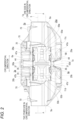
- a disc brake device 1a is an opposed piston type disc brake device used for braking an automobile, and includes a caliper 2a corresponding to a pad support member, an inner pad 3a and an outer pad 4a corresponding to pads, and a pad clip 20a.
- an axial direction, a circumferential direction and a radial direction refer to an axial direction, a circumferential direction and a radial direction of a disc-shaped rotor 5 that rotates together with wheels unless otherwise specified (see Fig. 2 ).
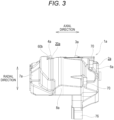
- a front-back direction in Figs. 1 , 5 to 10 , 12A , 12B , 13 and 16A, 16B, 16C , an upper-lower direction in Figs. 2 and 14 , and a left-right direction in Figs. 3 , 11 and 15 correspond to the axial direction.
- a side close to the rotor 5 in the axial direction is referred as an axially inner side, and a side far from the rotor 5 in the axial direction is referred as an axially outer side.
- a left-right direction in Figs. 1 , 2 , 5 to 10 , 12A , 12B , 13 , 14 and 16A, 16B, 16C , and a front-back direction in Figs. 3 , 11 and 15 correspond to the circumferential direction.
- the one side in the circumferential direction is a rotation-in side when a vehicle is moving forward and a rotation-out side when the vehicle is moving reversely
- the other side in the circumferential direction is a rotation-out side when the vehicle is moving forward and a rotation-in side when the vehicle is moving reversely.
- Figs. 1 , 3 , 5 to 13 , 15 and 16A, 16B, 16C , and a front-back direction in Figs. 2 and 14 correspond to the radial direction.
- An upper side in Figs. 1 , 3 , 5 to 13 , 15 and 16A, 16B, 16C , and a front side in Figs. 2 and 14 are a radially outer side, and a lower side in Figs. 1 , 3 , 5 to 13 , 15 and 16A, 16B, 16C , and a back side in Figs. 2 and 14 are a radially inner side.
- the rotation-in side refers to a side where the rotor 5 enters the caliper 2a
- the rotation-out side refers to a side where the rotor 5 exits from the caliper 2a.
- the caliper 2a has a substantially bow shape as viewed in the axial direction.
- the caliper 2a is fixed to a vehicle body and supports the inner pad 3a and the outer pad 4a so as to be movable in the axial direction.
- the caliper 2a is disposed so as to cover a part of the rotor 5 in the circumferential direction from the radially outer side, and is supported and fixed to a knuckle constituting a suspension device.
- the caliper 2a is molded by casting a material made of light alloy such as aluminum alloy, or iron-based alloy.
- the caliper 2a has a split type structure in which an inner side member and an outer side member are coupled by a plurality of bolts 70.
- the caliper 2a includes an inner body 6a, an outer body 7a, a first coupling portion 8a, a second coupling portion 9a and a pair of pins 11c, 11d.
- the inner body 6a and the outer body 7a are disposed on both sides of the rotor 5 in the axial direction so as to sandwich the rotor 5.
- the inner body 6a is disposed on an inner side (a center side) in a width direction of the vehicle with respect to the rotor 5, and includes a first inner cylinder 28a on the one side in the circumferential direction (the right side in Fig. 2 , the rotation-in side when moving forward and the rotation-out side when moving reversely), and a second inner cylinder 28b on the other side in the circumferential direction (the left side in Fig. 2 , the rotation-out side when moving forward and the rotation-in side when moving reversely).
- the inner body 6a includes a pair of attachment portions 76 for fixing the inner body 6 to the vehicle body, at a radially inner side portion.
- the outer body 7a is disposed on an outer side in the width direction of the vehicle with respect to the rotor 5, and includes a first outer cylinder 29a on the one side in the circumferential direction and a second outer cylinder 29b on the other side in the circumferential direction.
- the first inner cylinder 28a and the first outer cylinder 29a are coaxially disposed so as to face each other in the axial direction
- the second inner cylinder 28b and the second outer cylinder 29b are coaxially disposed so as to face each other in the axial direction.
- the first inner cylinder 28a and the second inner cylinder 28b communicate with each other through an oil passage (not shown) provided inside the inner body 6a.
- the first outer cylinder 29a and the second outer cylinder 29b communicate with each other through an oil passage (not shown) provided inside the outer body 7a.
- a piston (not shown) is fitted to each of the four cylinders 28a, 28b, 29a, 29b so as to be displaceable in the axial direction.
- a pair of overhanging wall portions 12c, 12d overhanging in the axial direction so as to approach the rotor 5 are respectively provided on both side portions of an axially inner side surface of the inner body 6a in the circumferential direction and on both side portions of an axially inner side surface of the outer body 7 in the circumferential direction.
- a first torque receiving surface 30 having a flat surface shape is provided on a side surface of the overhanging wall portion 12c disposed on the one side in the circumferential direction, at a radially inner side portion on the other side in the circumferential direction .
- a second torque receiving surface 32 having a flat surface shape is provided on a side surface of the overhanging wall portion 12d disposed on the other side in the circumferential direction, at a radially inner side portion on the one side in the circumferential direction.
- Each of the first coupling portion 8a and the second coupling portion 9a is disposed on the radially outer side of the rotor 5, and couples end portions of the inner body 6a and the outer body 7 in the circumferential direction to each other in the axial direction.
- the first coupling portion 8a couples the end portions of the inner body 6a and the outer body 7a on the one side in the circumferential direction to each other in the axial direction
- the second coupling portion 9a connects the end portions of the inner body 6a and the outer body 7a on the other side in the circumferential direction to each other in the axial direction.
- the first coupling portion 8a and the second coupling portion 9a are each curved in an arc shape along an outer peripheral edge of the rotor 5, and cover the rotor 5 from outside in the radial direction via a predetermined gap.
- a first moment bearing surface 31 having a flat surface shape is provided on a side surface of the first coupling portion 8a on the other side in the circumferential direction, the side surface of the first coupling portion 8a being located radially outward than the first torque receiving surface 30.
- a second moment bearing surface 33 having a flat surface shape is provided on a side surface of the second coupling portion 9a on the one side in the circumferential direction, the side surface of the second coupling portion 9a being located radially outward than the second torque receiving surface 32.
- Each of the pair of pins 11c, 11d has a cylindrical shape.
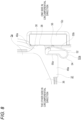
- Each of the pair of pins 11c, 11d is disposed parallel to a central axis of the rotor 5 on the radially outer side of the rotor 5. End portions of each of the pair of pins 11c, 11d in the axial direction are supported by radially outer side portions of the inner body 6a and the outer body 7a. Specifically, the end portions of each of the pair of pins 11c, 11d in the axial direction are respectively inserted into pin support holes 34 formed in the inner body 6a and the outer body 7a (see Fig. 1 ). Thereby, the pair of pins 11c, 11d are bridged between the inner body 6a and the outer body 7a.
- a stopper fitting 35 is locked to a portion of an intermediate portion of each of the pins 11c, 11d in the axial direction, the portion being located between the inner pad 3a and the inner body 6a. Thereby, the end portions of the pins 11c, 1 1d in the axial direction are prevented from coming out of the pin support holes 34 in the axial direction.
- An outer diameter of each of the pair of pins 11c, 11d is slightly smaller than an inner diameter of the pin support hole 34.
- the inner pad 3a and the outer pad 4a are disposed on both sides of the rotor 5 in the axial direction. Specifically, the inner pad 3a is disposed between the rotor 5 and the inner body 6a, and the outer pad 4a is disposed between the rotor 5 and the outer body 7a.
- Each of the inner pad 3a and the outer pad 4a includes a lining (a friction material) 36 and a metal back plate (a pressure plate) 37 supporting a back surface of the lining 36.
- the inner pad 3a and the outer pad 4a are the same components having the same shape and the same size. Therefore, the following description of details of each part will be focused only on the inner pad 3a.
- each of the lining 36 and the back plate 37 constituting the inner pad 3a has a line-symmetric shape with respect to a symmetry axis ⁇ passing through a central portion in the circumferential direction. Therefore, each of the lining 36 and the back plate 37 has the same shape at one side portion in the circumferential direction and the other side portion in the circumferential direction.
- a first torque transmission surface 38 having a flat surface shape is provided on a radially inner side portion, and a first moment transmission surface 39 having a flat surface shape is provided on a radially outer side portion.
- the first torque transmission surface 38 is provided on a tip end surface of a radially inner side protruding portion 40a.
- the radially inner side protruding portion 40a is located at a radially inner side portion of the one side portion of the back plate 37 in the circumferential direction, and protrudes to the one side in the circumferential direction from the lining 36.
- the first moment transmission surface 39 is provided on a tip end surface of a radially outer side protruding portion 41a.
- the radially outer side protruding portion 41a is located at a radially outer side end portion of the one side portion of the back plate 37 in the circumferential direction, and protrudes to the one side in the circumferential direction from the lining 36.
- a second torque transmission surface 42 having a flat surface shape is provided on a radially inner side portion, and a second moment transmission surface 43 having a flat surface shape is provided on a radially outer side portion.
- the second torque transmission surface 42 is provided on a tip end surface of a radially inner side protruding portion 40b.
- the radially inner side protruding portion 40b is located at a radially inner side portion of the other side portion of the back plate 37 in the circumferential direction, and protrudes to the other side in the circumferential direction from the lining 36.
- the second moment transmission surface 43 is provided on a tip end surface of a radially outer side protruding portion 41b.
- the radially outer side protruding portion 41b is located at a radially outer side end portion of the other side portion of the back plate 37 in the circumferential direction, and protrudes to the other side in the circumferential direction from the lining 36.
- the back plate 37 includes, at central portion of a radially outer side portion in the circumferential direction, a central protrusion 44 protruding radially outward from portions adjacent to both sides in the circumferential direction.
- the central protrusion 44 has a substantially rectangular shape.
- a clip insertion portion 45 penetrating in the axial direction is provided at a substantially central portion of the central protrusion 44 located at the central portion of the radially outer side portion of the back plate 37 in the circumferential direction.
- the clip insertion portion 45 is a through hole that opens only on both sides of the central protrusion 44 in the axial direction, and has a substantially rectangular shape.
- the clip insertion portion 45 has a circumferential width dimension larger than a radial width dimension.
- a pressed surface 46 having a flat surface shape is provided on a radially outer side portion of an inner peripheral surface of the clip insertion portion 45.
- a locking recess 73 for locking a claw piece 72 of a shim plate 71 disposed on a back side of the back plate 37 (see Fig. 6 ) is provided in a radially inner side portion of the inner peripheral surface of the clip insertion portion 45.
- the back plate 37 includes a pair of shoulder portions 47a, 47b protruding radially outward on both side portions of the radially outer side portion in the circumferential direction.
- the shoulder portion 47a on the one side in the circumferential direction is connected to the radially outer side protruding portion 41a on the one side in the circumferential direction
- the shoulder portion 47b on the other side in the circumferential direction is connected to the radially outer side protruding portion 41b on the other side in the circumferential direction.
- each of the pair of pin insertion portions 48a, 48b is a through hole that opens only on both sides of each of the shoulder portions 47a, 47b in the axial direction, and has a substantially rectangular shape.
- Each of the pair of pin insertion portions 48a, 48b has a circumferential width dimension larger than a radial width dimension. The radial width dimension and the circumferential width dimension of each of the pair of pin insertion portions 48a, 48b are larger than the outer diameter of each of the pins 11c, 11d.
- the back plate 37 includes a pair of leg portions 49a, 49b protruding radially inward on both side portions of a radially inner side portion in the circumferential direction.
- the leg portion 49a on the one side in the circumferential direction is connected to the radially inner side protruding portion 40a on the one side in the circumferential direction
- the leg portion 49b on the other side in the circumferential direction is connected to the radially inner side protruding portion 40b on the other side in the circumferential direction.
- a side surface, of the leg portion 49a on the one side in the circumferential direction, on the one side in the circumferential direction has a flat surface shape, and is located on the other side in the circumferential direction with respect to the first torque transmission surface 38 provided on the tip end surface of the radially inner side protruding portion 40a.
- a side surface, of the leg portion 49b on the other side in the circumferential direction, on the other side in the circumferential direction has a flat surface shape, and is located on the one side in the circumferential direction with respect to the second torque transmission surface 42 provided on the tip end surface of the radially inner side protruding portion 40b.
- a positioning recess 74 having a substantially rectangular shape recessed in the axial direction is provided on a back surface of each of the pair of leg portions 49a, 49b.
- a convex portion (a dowel) 50 protruding in the axial direction is provided at a substantially central portion of the positioning recess 74.
- Each of the inner pad 3a and the outer pad 4a further includes a pair of circumferential clips 5 1a, 51b.
- the pair of circumferential clips 51a, 51b are fixed to both side portions of the back plate 37 in the circumferential direction.
- the circumferential clips 51a, 51b are fixed to the leg portions 49a, 49b, respectively.
- Each of the circumferential clips 51a, 51b is made of a metal plate and includes a main body portion 52 bent in a substantially U shape and an attachment plate portion 53 having a substantially flat plate shape.
- the main body portion 52 includes a bent portion 54 having a partially cylindrical shape and a pair of pressing arm portions 55a, 55b connected to the bent portion 54.
- one pressing arm portion 55a is formed in a flat plate shape, whereas the other pressing arm portion 55b has a contact portion 56 bulging in a partially spherical shape at a portion close to a tip end.
- the attachment plate portion 53 extends in a substantially right angle direction from a tip end portion of the one pressing arm portion 55a.
- the circumferential clip 51a is fixed to the leg portion 49a in a state where the main body portion 52 is disposed in a space located on the one side in the circumferential direction of the leg portion 49a on the one side in the circumferential direction and on the radially inner side of the radially inner side protruding portion 40a.
- the attachment plate portion 53 is fixed to the back surface of the leg portion 49a by disposing the attachment plate portion 53 in the positioning recess 74 provided on the back surface of the leg portion 49a, inserting the convex portion 50 into a through hole 57 provided in the attachment plate portion 53, and caulking and deforming a tip end portion of the convex portion 50.
- the circumferential clip 51b is fixed to the leg portion 49b in a state where the main body portion 52 is disposed in a space located on the other side in the circumferential direction of the leg portion 49b on the other side in the circumferential direction and on the radially inner side of the radially inner side protruding portion 40b.
- the attachment plate portion 53 is fixed to the back surface of the leg portion 49b by disposing the attachment plate portion 53 in the positioning recess 74 provided on the back surface of the leg portion 49b, inserting the convex portion 50 into the through hole 57 provided in the attachment plate portion 53, and caulking and deforming the tip end portion of the convex portion 50.
- the respective bent portions 54 are located radially inward than a radially inner end edge of the back plate 37, and the respective contact portions 56 are located slightly radially inward than a radially inner end edge of the lining 36.
- the inner pad 3a and the outer pad 4a are supported by the caliper 2a so as to be movable in the axial direction by using the pair of pins 11c, 11d. Therefore, in the pair of pin insertion portions 48a, 48b provided in the back plate 37, the pin 11c disposed on the one side in the circumferential direction is inserted in the axial direction into the pin insertion portion 48a disposed on the one side in the circumferential direction, and the pin 11d disposed on the other side in the circumferential direction is inserted in the axial direction into the pin insertion portion 48b disposed on the other side in the circumferential direction.
- the first torque transmission surface 38 and the first moment transmission surface 39 provided on the side surface of the back plate 37 on the one side in the circumferential direction respectively face, in the circumferential direction, the first torque receiving surface 30 provided on the overhanging wall portion 12c on the one side in the circumferential direction and the first moment bearing surface 31 provided on the first coupling portion 8a.
- the second torque transmission surface 42 and the second moment transmission surface 43 provided on the side surface of the back plate 37 on the other side in the circumferential direction respectively face, in the circumferential direction, the second torque receiving surface 32 provided on the overhanging wall portion 12d on the other side in the circumferential direction and the second moment bearing surface 33 provided on the second coupling portion 9a.
- each of the pair of circumferential clips 51a, 51b is elastically deformed between each of the inner pad 3a and the outer pad 4a and the caliper 2a.
- the circumferential clip 51a on the one side in the circumferential direction is elastically deformed between the side surface, of the leg portion 49a provided in the back plate 37, on the one side in the circumferential direction, and the side surface (the first torque receiving surface 30), of the overhanging wall portion 12c provided in the caliper 2a, on the other side in the circumferential direction.
- the circumferential clip 51a presses each of the inner pad 3a and the outer pad 4a and the caliper 2a in directions opposite to each other in the circumferential direction.
- the circumferential clip 51a presses radially inner side portions of the side surface of the leg portion 49a in the circumferential direction and the side surface of the overhanging wall portion 12c on the other side in the circumferential direction, the portions being slightly radially inward than the radially inner end edge of the lining 36, where the contact portion 56 is located.
- the circumferential clip 51b on the other side in the circumferential direction is elastically deformed between the side surface, of the leg portion 49b provided in the back plate 37, on the other side in the circumferential direction, and the side surface (the second torque receiving surface 32), of the overhanging wall portion 12d provided in the caliper 2a, on the one side in the circumferential direction. Then, each of the inner pad 3a and the outer pad 4a and the caliper 2a are pressed in directions opposite to each other in the circumferential direction.
- the circumferential clip 5 1b presses radially inner side portions of the side surface of the leg portion 49b in the circumferential direction and the side surface of the overhanging wall portion 12d on the one side in the circumferential direction, the portions being slightly radially inward than the radially inner end edge of the lining 36, where the contact portion 56 is located.
- the circumferential clip 51a disposed on the one side in the circumferential direction presses a radially inner side portion of each of the inner pad 3a and the outer pad 4a toward the other side in the circumferential direction.
- the circumferential clip 51b disposed on the other side in the circumferential direction presses the radially inner side portion of each of the inner pad 3a and the outer pad 4a toward the one side in the circumferential direction. Since pressing forces of the pair of circumferential clips 51a, 51b are equal to each other, each of the inner pad 3a and the outer pad 4a is elastically held (centered) at a neutral position in the circumferential direction.
- the pad clip 20a is a component for preventing occurrence of a brake noise during light braking in which brake fluid has a low hydraulic pressure.
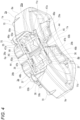
- the pad clip 20a is made of a metal plate having elasticity and corrosion resistance such as a stainless steel plate, and has a substantially cross shape as viewed in the radial direction (in a plan view) (see Figs. 2 and 14 ).
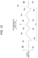
- the pad clip 20a is integrally formed as a whole, and includes a substrate portion 58 extending in the axial direction, and a pair of circumferential arm portions 59a, 59b extending in directions away from each other in the circumferential direction from an intermediate portion of the substrate portion 58 in the axial direction.
- the substrate portion 58 in a mounted state of the pad clip 20a, is disposed between the pair of pins 11c, 11d in the circumferential direction and on the radially outer side of the rotor 5.
- the substrate portion 58 has a chevron-shaped cross section that is convex on a radially outer side.
- the cross-sectional shape of the substrate portion 58 is constant in the axial direction.
- the substrate portion 58 includes a pad pressing portion 60a that is inserted into the clip insertion portion 45 of the inner pad 3a in the axial direction at an end portion on one side in the axial direction, and includes a pad pressing portion 60b that is inserted into the clip insertion portion 45 of the outer pad 4a in the axial direction at an end portion on the other side in the axial direction. That is, the substrate portion 58 includes the pair of pad pressing portions 60a, 60b disposed at both end portions in the axial direction. As shown in Fig.
- each of the pair of pad pressing portions 60a, 60b has a pressing surface 61 having a flat surface shape, which is in surface contact with the pressed surface 46 constituting the inner peripheral surface of the clip insertion portion 45, on a radially outer side end surface.
- each of the pair of circumferential arm portions 59a, 59b is disposed between the inner pad 3a and the outer pad 4a and on the radially outer side of the rotor 5.
- each of the pair of circumferential arm portions 59a, 59b has a corrugated shape undulating in the radial direction (a plate thickness direction).
- the pair of circumferential arm portions 59a, 59b respectively include first curved portions 62a, 62b, second curved portions 63a, 63b, third curved portions 64a, 64b, pin pressing portions 65a, 65b, and tip end plate portions 66a, 66b in this order from the substrate portion 58.
- Each of the first curved portions 62a, 62b is located at a base end portion of each of the circumferential arm portions 59a, 59b, and is connected to an intermediate portion of the substrate portion 58 in the axial direction.
- the first curved portions 62a, 62b are curved so as to be convex on a radially inner side.
- Each of the first curved portions 62a, 62b is a tapered portion whose axial width decreases toward a tip end side in the circumferential direction.
- Each of the second curved portions 63a, 63b is located at an intermediate portion of each of the circumferential arm portions 59a, 59b.
- the second curved portions 63a, 63b are curved so as to be convex on the radially outer side.
- a radially outer side end portion of each of the second curved portions 63a, 63b is located radially outward than the pressing surface 61 of each of the pad pressing portions 60a, 60b.
- Each of the third curved portions 64a, 64b is located at the intermediate portion of each of the circumferential arm portions 59a, 59b.
- the third curved portions 64a, 64b are curved so as to be convex on the radially inner side.
- a radially inner side end portion of each of the third curved portions 64a, 64b is located on the radially innermost side of the pad clip 20a.
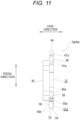
- a circumferential interval H64 between side surfaces of the pair of third curved portions 64a, 64b on sides far from each other in the circumferential direction is slightly larger than a circumferential interval H11 between end portions of the pair of pins 11c, 11d on sides close to each other in the circumferential direction (see Fig. 7 ) (H64 > H11).
- Each of the pin pressing portions 65a, 65b is located at a portion near a tip end portion of each of the circumferential arm portions 59a, 59b.
- Each of the pin pressing portions 65a, 65b has a semi-cylindrical shape that is curved so as to be convex on the radially outer side.
- Each of the pin pressing portions 65a, 65b has a radius of curvature slightly larger than half the outer diameter of each of the pins 11c, 11d.
- a radially outer side end portion of each of the pin pressing portions 65a, 65b is located in the radial direction between a radially inner side end portion of each of the first curved portions 62a, 62b and a radially outer side end portion of each of the second curved portions 63a, 63b.
- the tip end plate portions 66a, 66b are located at the tip end portions of the circumferential arm portions 59a, 59b, respectively. Each of the tip end plate portions 66a, 66b is formed in a flat plate shape.
- the pad clip 20a is elastically deformed between the inner pad 3a and the outer pad 4a, and the pair of pins 11c, 11d.
- the pair of pad pressing portions 60a, 60b provided at end portions of the substrate portion 58 on both sides in the axial direction are respectively inserted in the axial direction into the clip insertion portions 45 provided in the inner pad 3a and the outer pad 4a, and the pair of pin pressing portions 65a, 65b are respectively locked to the pair of pins 11c, 11d from the radially outer side.
- the pair of circumferential arm portions 59a, 59b are bent and deformed in the radial direction.
- the pad clip 20a presses the inner pad 3a and the outer pad 4a radially outward by the pair of pad pressing portions 60a, 60b, and presses the pair of pins 11c, 11d radially inward by the pair of pin pressing portions 65a, 65b. That is, the pad clip 20a applies pressing forces radially outward to the inner pad 3a and the outer pad 4a by using the pair of pins 11c, 11d as anchors (supporting reaction forces by the pins 11c, 11d). Thereby, as shown in Fig.
- a radially inner side portion of an inner peripheral surface of each of the pair of pin insertion portions 48a, 48b is pressed against a radially inner side end portion of each of the pair of pins 11c, 11d.
- the radially inner side portion of the inner peripheral surface of each of the pair of the pin insertion portions 48a, 48b is a portion of the inner peripheral surface of each of the pair of the pin insertion portions 48a, 48b in the radially inner side of the rotor 5.
- the radially inner side end portion of each of the pair of the pins 11c, 11d is an end portion of each of the pair of the pins 11c, 11d in the radially inner side the rotor 5. Therefore, a gap is formed between a radially outer side portion of the inner peripheral surface of each of the pair of pin insertion portions 48a, 48b and a radially outer side end portion of each of the pair of pins 11c, 11d.
- the pressing surface 61 provided in each of the pair of pad pressing portions 60a, 60b is in surface contact with the pressed surface 46 of the clip insertion portion 45 provided in each of the inner pad 3a and the outer pad 4a.
- the pair of pin pressing portions 65a, 65b further press the pair of pins 11c, 11d in directions opposite to each other in the circumferential direction. That is, the pin pressing portion 65a on the one side in the circumferential direction presses the pin 11c on the one side in the circumferential direction toward the one side in the circumferential direction, and the pin pressing portion 65b on the other side in the circumferential direction presses the pin 11d on the other side in the circumferential direction toward the other side in the circumferential direction.
- the pin 11c on the one side in the circumferential direction is pressed against one side portion in the circumferential direction of an inner circumferential surface of the pin support hole 34 on the one side in the circumferential direction
- the pin 11d on the other side in the circumferential direction is pressed against the other side portion in the circumferential direction of the inner circumferential surface of the pin support hole 34 on the other side in the circumferential direction.
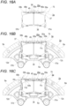
- the pair of pad pressing portions 60a, 60b provided in the pad clip 20a are respectively inserted into the clip insertion portions 45 of the inner pad 3a and the outer pad 4a to obtain a pad assembly 75 including the pad clip 20a, the inner pad 3a and the outer pad 4a.
- the pad assembly 75 is assembled from the radially outer side into a portion between the inner body 6a and the outer body 7a constituting the caliper 2a. Then, as shown in Fig. 16B , the inner pad 3a and the outer pad 4a are suspended from the caliper 2a by one pin 11c (11d) of the pair of pins 11c, 11d. That is, the one pin 11c (11d) is inserted in the axial direction into one pin support hole 34 provided in each of the inner body 6a and the outer body 7a and one pin insertion portion 48a (48b) provided in each of the inner pad 3a and the outer pad 4a. Then, one pin pressing portion 65a (65b) provided in the pad clip 20a is locked to the one pin 11c (11d) from the radially outer side.
- the other circumferential arm portion 59b (59a) provided with the other pin pressing portion 65b (65a) is pulled up (bent and deformed) radially outward while gripping the tip end plate portion 66b (66a).
- the other pin 11d (11c) is inserted in the axial direction into the other pin support hole 34 provided in each of the inner body 6a and the outer body 7a and the other pin insertion portion 48b (48a) provided in each of the inner pad 3a and the outer pad 4a.
- the circumferential interval H64 between the side surfaces of the pair of third curved portions 64a, 64b on the sides far from each other in the circumferential direction is set to be slightly larger than the circumferential interval H11 between the end portions of the pair of pins 11c, 11d on the sides close to each other in the circumferential direction. Therefore, as shown in Fig.
- a radially inner side portion of the third curved portion 64b (64a) provided on the other circumferential arm portion 59b (59a) comes into abutting (rides on) a radially outer side portion of the other pin 11d (11c). Therefore, by further pushing the other circumferential arm portion 59b (59a) radially inward, in the other circumferential arm portion 59a (59b), the other pin pressing portion 65b (65a) is locked to the other pin 11d (11c) from the radially outer side while mainly elastically deforming the third curved portion 64b (64a) in the circumferential direction.
- the brake fluid is fed from a master cylinder to the first inner cylinder 28a and the second inner cylinder 28b provided in the inner body 6a and the first outer cylinder 29a and the second outer cylinder 29b provided in the outer body 7a.
- the piston (not shown) provided in each of the inner body 6a and the outer body 7a is pushed out in the axial direction, and the inner pad 3a and the outer pad 4a are pressed against both side surfaces of the rotor 5 in the axial direction.
- the rotor 5 is strongly sandwiched by the inner pad 3a and the outer pad 4a from both sides in the axial direction, and the vehicle is braked.
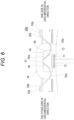
- the disc brake device 1a according to the present embodiment generates the following moment in each of the inner pad 3a and the outer pad 4a at during braking.
- a brake tangential force F1 directed to the other side in the circumferential direction acts on a point A at a friction surface center of the lining 36 of the inner pad 3a (the outer pad 4a).
- the second torque transmission surface 42 disposed on the other side in the circumferential direction comes into abutting the second torque receiving surface 32 to support the brake tangential force F1.
- an abutting portion between the second torque transmission surface 42 and the second torque receiving surface 32 is located radially inward than the point A at the friction surface center on which the brake tangential force F1 acts.
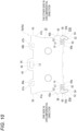
- a moment M1 acts on the inner pad 3a and the outer pad 4a in a direction in which one side portion in the circumferential direction, which is a rotation-in side portion when moving forward, is pushed up toward the radially outer side, and the other side portion in the circumferential direction, which is a rotation-out side portion when moving forward, is pushed down toward the radially inner side.
- the moment M1 is supported by rotating the inner pad 3a (the outer pad 4a) counterclockwise and bringing the second moment transmission surface 43 disposed on the other side in the circumferential direction into abutting the second moment bearing surface 33. That is, during forward braking, a posture of each of the inner pad 3a and the outer pad 4a is restrained at two portions by the abutting portion between the second torque transmission surface 42 and the second torque receiving surface 32 and an abutting portion between the second moment transmission surface 43 and the second moment bearing surface 33.
- the point A at the friction surface center is a centroid of a friction surface, and is determined by a diameter, arrangement and the like of the piston.
- a brake tangential force F2 directed to the one side in the circumferential direction acts on the point A at the friction surface center of the lining 36 of the inner pad 3a (the outer pad 4a).
- the first torque transmission surface 38 disposed on the one side in the circumferential direction comes into abutting the first torque receiving surface 30 to support the brake tangential force F2.
- an abutting portion between the first torque transmission surface 38 and the first torque receiving surface 30 is located radially inward than the point A at the friction surface center on which the brake tangential force F2 acts.
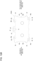
- a moment M2 acts on the inner pad 3a and the outer pad 4a in a direction in which the other side portion in the circumferential direction, which is a rotation-in side portion when moving reversely, is pushed up toward the radially outer side, and one side portion in the circumferential direction, which is a rotation-out side portion when moving reversely, is pushed down toward the radially inner side.
- the moment M2 is supported by rotating the inner pad 3a (the outer pad 4a) clockwise and bringing the first moment transmission surface 39 disposed on the one side in the circumferential direction into contact with the first moment bearing surface 31. That is, during reverse braking, the posture of each of the inner pad 3a and the outer pad 4a is restrained at two portions by the abutting portion between the first torque transmission surface 38 and the first torque receiving surface 30 and an abutting portion between the first moment transmission surface 39 and the first moment bearing surface 31.
- the occurrence of the brake noise can be prevented even during light braking in which the brake fluid has the low hydraulic pressure.
- the pair of pad pressing portions 60a, 60b included in the pad clip 20a apply the pressing forces radially outward to the inner pad 3a and the outer pad 4a, and press the radially inner side portions of the inner peripheral surfaces of the pair of pin insertion portions 48a, 48b respectively against the radially inner side end portions of the pair of pins 11c, 11d.
- each of the inner pad 3a and the outer pad 4a can be rotated counterclockwise by the small moment M1 acting on each of the inner pad 3a and the outer pad 4a, and the second moment transmission surface 43 can be easily brought into abutting the second moment bearing surface 33.
- the posture of each of the inner pad 3a and the outer pad 4a can be stabilized, and the occurrence of the brake noise can be prevented.
- each of the inner pad 3a and the outer pad 4a can be rotated clockwise by the small moment M2 acting on each of the inner pad 3a and the outer pad 4a, and the first moment transmission surface 39 can be easily brought into abutting the first moment bearing surface 31.
- the posture of each of the inner pad 3a and the outer pad 4a can be stabilized, and the occurrence of the brake noise can be prevented.
- the pad clip 20a applies the pressing forces in the directions opposite to each other in the circumferential direction to the pair of pins 11c, 11d, whereby the pair of pins 11c, 11d are pressed against inner surfaces of the pin support holes 34 respectively provided in the inner body 6a and the outer body 7a. Therefore, when each of the inner pad 3a and the outer pad 4a is rotated counterclockwise during forward braking, the pin 11c on the one side in the circumferential direction can be moved radially outward along the inner surface of the pin support hole 34 disposed on the one side in the circumferential direction.
- the pressing surface 61 provided in the pad pressing portions 60a, 60b is a flat surface and the pressed surface 46 provided in the clip insertion portion 45 is a flat surface, a surface pressure of an abutting portion between the pressing surface 61 and the pressed surface 46 can be suppressed. Therefore, wear of the pressing surface 61 and the pressed surface 46 can be suppressed. During braking, the pressed surface 46 can be smoothly displaced in the axial direction with respect to the pressing surface 61.
- the pair of circumferential arm portions 59a, 59b each have the corrugated shape including the first curved portions 62a, 62b, the second curved portions 63a, 63b, and the third curved portions 64a, 64b, the pressing forces (spring loads) by the pair of pad pressing portions 60a, 60b can be increased in comparison with a case where the pair of circumferential arm portions 59a, 59b both have a flat plate shape in a limited volume. Since each of the first curved portions 62a, 62b is the tapered portion whose axial width decreases as being away from the substrate portion 58, the pressing forces by the pair of pad pressing portions 60a, 60b can be increased also from this surface.
- each of the inner pad 3a and the outer pad 4a is pressed in the directions opposite to each other in the circumferential direction by the circumferential clips 51a, 51b provided on both side portions of each of the inner pad 3a and the outer pad 4a in the circumferential direction.
- the circumferential clips 51a, 51b press each of the inner pad 3a and the outer pad 4a toward a central side in the circumferential direction.
- each of the inner pad 3a and the outer pad 4a can be elastically held at the neutral position in the circumferential direction, and a size of a circumferential gap between the first torque transmission surface 38 and the first torque receiving surface 30 and a size of a circumferential gap between the second torque transmission surface 42 and the second torque receiving surface 32 can be prevented from becoming unnecessarily large (can be made substantially equal to each other). Therefore, during forward braking, the second torque transmission surface 42 and the second torque receiving surface 32 can be prevented from vigorously colliding with each other to cause an abnormal noise (a click sound), and during reverse braking, the first torque transmission surface 38 and the first torque receiving surface 30 can be prevented from vigorously colliding with each other to cause an abnormal noise.
- the circumferential clips 51a, 51b press portions of the side surfaces of the leg portions 49a, 49b in the circumferential direction and the side surfaces of the overhanging wall portions 12c, 12d in the circumferential direction, respectively, the portions being located slightly radially inward than the radially inner end edge of the lining 36. Therefore, when the braking force is released, an inclination angle of each of the inner pad 3a and the outer pad 4a can be sufficiently reduced. Therefore, dragging of the inner pad 3a and the outer pad 4a can be reduced.
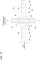
- a second embodiment will be described with reference to Fig. 17 .
- the same components as those of the first embodiment are denoted by the same reference numerals as those of the first embodiment, and detailed description thereof will be omitted.
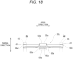
- a pad clip 20b has a cross shape as viewed in the radial direction, similarly to a structure according to the first embodiment, but the entire pad clip 20b is not formed as an integrated structure and includes a long plate-shaped axial member 67 and a long plate-shaped circumferential member 68 separate from the axial member 67.
- the axial member 67 is formed of the substrate portion 58, and has the pair of pad pressing portions 60a, 60b at both end portions in the axial direction.
- the circumferential member 68 includes the pair of circumferential arm portions 59a, 59b and a connection base portion 69 that connects base end portions of the circumferential arm portions 59a, 59b to each other in the circumferential direction.
- the connection base portion 69 is disposed on the radially inner side of an intermediate portion of the axial member 67 (the substrate portion 58) in the axial direction, and is caulking-fixed to the axial member 67 by one or a plurality of caulking portions (not shown).
- the pad clips 20b is configured by fixing the long plate-shaped axial member 67 and the long plate-shaped circumferential member 68, and thus a plate removal property of a metal plate can be improved as compared with the structure according to the first embodiment. Therefore, a manufacturing cost of the pad clip 20b can be reduced.
- a configuration in which the long plate-shaped axial member and the long plate-shaped circumferential member separate from the axial member are fixed by riveting instead of caulking may be adopted.
- an effect of reducing the manufacturing cost of the pad clip can be obtained as in a case of adopting caulking fixation.
- a third embodiment will be described with reference to Fig. 18 .
- the same components as those of the first embodiment are denoted by the same reference numerals as those of the first embodiment, and detailed description thereof will be omitted.
- shapes of a pair of pad pressing portions 60c, 60d constituting a pad clip 20c are different from those in the structure according to the first embodiment.
- Each of the pair of pad pressing portions 60c, 60d is inclined in a direction radially inward toward a side away from the rotor 5 in the axial direction (both left and right sides in Fig. 18 ). Thereby, each of the inner pad 3a and the outer pad 4a is pressed radially outward by the pair of pad pressing portions 60c, 60d, and is pressed in a direction away from the rotor 5 in the axial direction.
- each of the inner pad 3a and the outer pad 4a can be separated from the rotor 5 in the axial direction by the pad pressing portions 60c, 60d. Therefore, dragging of the inner pad 3a and the outer pad 4a can be reduced.
- Other configurations and operational effects are the same as those of the first embodiment.
- the caliper serving as the pad support member is not limited to the split type structure as described in the embodiment, and an integrated type structure (a monocoque structure) can be adopted.
- the disc brake device according to the present invention is not limited to the opposed piston type disc brake device as described in each embodiment, and can also be applied to a floating caliper type disc brake device.
Landscapes
- Engineering & Computer Science (AREA)
- General Engineering & Computer Science (AREA)
- Mechanical Engineering (AREA)
- Transportation (AREA)
- Braking Arrangements (AREA)
Claims (22)
- Dispositif de frein à disque (1a) dans lequel un moment (M1, M2) agit sur une plaquette (3a, 4a) dans une direction dans laquelle une partie latérale en rotation est poussée en direction d'un flanc radialement externe pendant un freinage, le dispositif de frein à disque (1a) comprenant :la plaquette (3a, 4a) incluant un organe d'insertion de broche (12c, 12d) et un organe d'insertion d'attache (45),un élément de support de plaquette incluant une broche (11c, 11d) insérée dans l'organe d'insertion de broche (12c, 12d) dans la direction axiale et supportant la plaquette (3a, 4a) de sorte à ce que la plaquette (3a, 4a) puisse se déplacer dans la direction axiale, etune attache de plaquette (20a, 20b, 20c) incluant un organe de pressage de plaquette (60a, 60b, 60c, 60d) inséré dans l'organe d'insertion d'attache (45) dans la direction axiale et configurée pour presser la plaquette (3a, 4a) radialement vers l'extérieur,dans lequel l'attache de plaquette (20a, 20b, 20c) est configurée pour appliquer une force de pressage sur la plaquette (3a, 4a) de sorte à ce qu'un flanc radialement interne de la surface périphérique interne de l'organe d'insertion de broche (12c, 12d) soit pressé contre un flanc radialement interne de la broche (11c, 11d),caractérisé en ce que :
l'attache de plaquette (20a, 20b, 20c) est déformée élastiquement entre la plaquette (3a, 4a) et la broche (11c, 11d) et applique sur la plaquette (3a, 4a) la force de pressage radialement vers l'extérieur. - Dispositif de frein à disque (1a) selon la revendication 1,
dans lequel l'élément de support de plaquette est un étrier (2) incluant un corps interne (6a) et un corps externe (7a) disposés avec un rotor (5) intercalé entre le corps interne (6a) et le corps externe (7a). - Dispositif de frein à disque (1a) selon la revendication 2,
dans lequel l'élément de support de plaquette inclut une surface de réception de couple (30, 32) au niveau d'un flanc radialement interne d'une partie latérale hors rotation et une surface de support de moment (31, 33) au niveau d'un flanc radialement externe de la partie latérale hors rotation, la surface de réception de couple (30, 32) supportant une force tangentielle (F1, F2) agissant sur la plaquette (3a, 4a) pendant le freinage, et la surface de support de moment (31, 33) supportant le moment (M1, M2) agissant sur la plaquette (3a, 4a) dans la direction dans laquelle la partie latérale en rotation de la plaquette (3a, 4a) est poussé en direction du flanc radialement externe pendant le freinage. - Dispositif de frein à disque (1a) selon l'une quelconque des revendications 1 à 3, comprenant :une paire de plaquettes (3a, 4a), etdans lequel les deux plaquettes (3a, 4a) sont un même composant.
- Dispositif de frein à disque (1a) selon l'une quelconque des revendications 1 à 4,
dans lequel la plaquette (3a, 4a) inclut l'organe d'insertion d'attache 45) au niveau de la partie centrale d'un flanc radialement externe dans la direction circonférentielle. - Dispositif de frein à disque (1a) selon l'une quelconque des revendications 1 à 5,dans lequel la plaquette (3a, 4a) inclut une paire des organes d'insertion de broche (12c, 12d) sur les deux côtés du flanc radialement externe dans la direction circonférentielle de sorte à ce que les deux côtés enserrent l'organe d'insertion d'attache (45), etdans lequel l'élément de support de plaquette inclut une paire de broches (11c, 11d) insérées respectivement dans la paire d'organes d'insertion de broche (12c, 12d).
- Dispositif de frein à disque (1a) selon la revendication 6,dans lequel l'attache de plaquette (20a, 20b, 20c) est constituée d'une plaque de métal et inclut un substrat (58) incluant l'organe de pressage de plaquette (60a, 60b, 60c, 60d) au niveau d'une extrémité dans la direction axiale et une paire de bras circonférentiels (59a, 59b) s'étendant depuis le substrat (58) dans des directions les écartant l'un de l'autre dans la direction circonférentielle, etdans lequel chaque bras de la paire de bras circonférentiels (59a, 59b) inclut un organe de pressage de broche (65a, 65b) placé sur un flanc radialement externe de la broche (11c, 11d) et configuré pour presser la broche (11c, 11d) radialement vers l'intérieur.
- Dispositif de frein à disque (1a) selon la revendication 7,
dans lequel l'attache de plaquette (20a, 20b, 20c) presse en outre la paire de broches (11c, 11d) dans des sens opposés l'un à l'autre dans la direction circonférentielle. - Dispositif de frein à disque (1a) selon la revendication 7 ou la revendication 8,
dans lequel le bras circonférentiel (59a, 59b) une forme cannelée ondulant dans une direction radiale. - Dispositif de frein à disque (1a) selon la revendication 9,
dans lequel le bras circonférentiel (59a, 59b) inclut, entre le substrat (58) et l'organe de pressage de broche (65a, 65b), une première partie incurvée (62a, 62b) incurvée de sorte à être convexe sur un flanc radialement interne, une deuxième partie incurvée (63a, 63b) incurvée de sorte à être convexe sur un flanc radialement externe et une troisième partie incurvée (64a, 64b) incurvée de sorte à être convexe sur un flanc radialement interne, dans l'ordre du plus proche du substrat (58). - Dispositif de frein à disque (1a) selon la revendication 10,
dans lequel, lorsque l'attache de plaquette (20a, 20b, 20c) est libre, l'intervalle circonférentiel entre des surfaces latérales de la paire de troisièmes parties incurvées (64a, 64b) sur des côtés éloignés l'un de l'autre dans la direction circonférentielle est plus large que l'intervalle circonférentiel entre les extrémités de la paire de broches (11c, 11d) sur les côtés proches l'un de l'autre dans la direction circonférentielle. - Dispositif de frein à disque (1a) selon l'une quelconque des revendications 7 à 11,
dans lequel le bras circonférentiel (59a, 59b) inclut en outre une partie tronconique dont la largeur axiale diminue à mesure qu'il est à distance du substrat (58) dans la direction circonférentielle. - Dispositif de frein à disque (1a) selon l'une quelconque des revendications 7 à 12, comprenant :la paire de plaquettes (3a, 4a),dans lequel l'attache de plaquette (20a, 20b, 20c) présente une forme en coupe telle que visualisée dans la direction radiale, etdans lequel le substrat (58) inclut une paire d'organes de pressage de plaquette (60a, 60b, 60c, 60d) placés aux extrémités sur les deux côtés dans la direction axiale et insérés respectivement dans les organes d'insertion d'attache (45) disposés dans la paire de plaquettes (3a, 4a) .
- Dispositif de frein à disque (1a) selon la revendication 13,
dans lequel l'attache de plaquette (20b) inclut un élément axial (67) comprenant le substrat (58) et s'étendant dans la direction axiale, ainsi qu'un élément circonférentiel (68) formé séparément de l'élément axial (67), incluant la paire de bras circonférentiels (59a, 59b) et s'étendant dans la direction circonférentielle. - Dispositif de frein à disque (1a) selon la revendication 14,
dans lequel l'élément axial (67) élément circonférentiel (68) sont fixés par matage ou rivetage. - Dispositif de frein à disque (1a) selon l'une quelconque des revendications 1 à 15,
dans lequel l'organe de pressage de plaquette (60a, 60b, 60c, 60d) inclut, sur une surface d'extrémité latérale externe, une surface de pressage en forme de surface plane configurée pour se trouver en contact de surface avec une partie de flanc radialement externe dans une surface périphérique interne de l'organe d'insertion d'attache (45). - Dispositif de frein à disque (1a) selon l'une quelconque des revendications 1 à 16,
dans lequel l'organe de pressage de plaquette (60c, 60d) est incliné dans une direction radialement vers l'intérieur à mesure qu'il est à distance du rotor (5) dans la direction axiale, et il presse la plaquette (3a, 4a) radialement vers l'extérieur et dans une direction à distance du rotor (5) dans la direction axiale. - Dispositif de frein à disque (1a) selon l'une quelconque des revendications 1 à 17, comprenant en outre :
une attache circonférentielle (51a, 51b) configurée pour être déformée élastique non entre la plaquette (3a, 4a) et l'élément de support de plaquette et pour presser la plaquette (3a, 4a) et l'élément de support de plaquette dans des sens opposés l'un à l'autre dans la direction circonférentielle. - Dispositif de frein à disque (1a) selon la revendication 18, comprenant :une paire d'attaches circonférentielles (51a, 51b),dans lequel une attache circonférentielle (51a) presse la plaquette (3a, 4a) en direction d'un côté dans la direction circonférentielle, et l'autre attache circonférentielle (51b) presse la plaquette (3a, 4a) vers l'autre côté dans la direction circonférentielle.
- Dispositif de frein à disque (1a) selon la revendication 18 ou la revendication 19,
dans lequel l'attache circonférentielle (51a, 51b) presse une partie latérale radialement interne de la plaquette (3a, 4a). - Dispositif de frein à disque (1a) selon l'une quelconque des revendications 18 à 20,
dans lequel l'attache circonférentielle (51a, 51b) est fixée à la plaquette (3a, 4a). - Dispositif de frein à disque (1a) selon l'une quelconque des revendications 18 à 21,
dans lequel l'attache circonférentielle (51a, 51b) presse des parties de la plaquette (3a, 4a) et de l'élément de support de plaquette, les parties présentant des positions radiales identiques à celles d'un bord d'extrémité radialement interne d'une doublure (36) incluse dans la plaquette (3a, 4a) ou bien des parties situées radialement plus vers l'intérieur que le bord d'extrémité radialement interne de la doublure (36).
Applications Claiming Priority (1)
| Application Number | Priority Date | Filing Date | Title |
|---|---|---|---|
| JP2020134920A JP7456885B2 (ja) | 2020-08-07 | 2020-08-07 | ディスクブレーキ装置 |
Publications (2)
| Publication Number | Publication Date |
|---|---|
| EP3954921A1 EP3954921A1 (fr) | 2022-02-16 |
| EP3954921B1 true EP3954921B1 (fr) | 2024-01-17 |
Family
ID=77226695
Family Applications (1)
| Application Number | Title | Priority Date | Filing Date |
|---|---|---|---|
| EP21189868.9A Active EP3954921B1 (fr) | 2020-08-07 | 2021-08-05 | Dispositif de frein à disque |
Country Status (4)
| Country | Link |
|---|---|
| US (1) | US11946519B2 (fr) |
| EP (1) | EP3954921B1 (fr) |
| JP (1) | JP7456885B2 (fr) |
| CN (1) | CN114060437B (fr) |
Families Citing this family (1)
| Publication number | Priority date | Publication date | Assignee | Title |
|---|---|---|---|---|
| KR20210105612A (ko) * | 2020-02-19 | 2021-08-27 | 현대모비스 주식회사 | 차량용 브레이크 장치 |
Family Cites Families (34)
| Publication number | Priority date | Publication date | Assignee | Title |
|---|---|---|---|---|
| DE1182087B (de) * | 1962-12-05 | 1964-11-19 | Teves Kg Alfred | Teilbelagscheibenbremse, insbesondere fuer Kraftfahrzeuge |
| GB1223989A (en) * | 1968-07-11 | 1971-03-03 | Teves Gmbh Alfred | Floating caliper disc brake |
| US3783980A (en) * | 1971-10-13 | 1974-01-08 | Itt | Brake lining holding arrangement for spot-type disc brakes |
| FR2199828A5 (fr) * | 1972-05-12 | 1974-04-12 | Bendix Gmbh | |
| DE2301595C3 (de) * | 1973-01-13 | 1975-09-11 | Daimler-Benz Ag, 7000 Stuttgart | Bremsbackenhalte- und -abstützeinrichtung für die Bremsbacken einer Teilbelagscheibenbremse, insbesondere für Kraftfahrzeuge |
| FR2425579A1 (fr) * | 1978-05-11 | 1979-12-07 | Dba | Frein a disque et ressort anti-bruit pour un tel frein |
| US4290508A (en) * | 1978-09-14 | 1981-09-22 | Lucas Industries Limited | Disc brake pad assemblies |
| JPS6110018Y2 (fr) * | 1979-10-16 | 1986-04-01 | ||
| AU6759981A (en) * | 1980-03-01 | 1981-09-10 | Lucas Industries Limited | Disc brakes and friction pad assemblies therefor |
| DE3910154C2 (de) * | 1989-03-29 | 1998-07-02 | Perrot Bremse Gmbh Deutsche | Blattfederanordnung zum Niederhalten der Bremsbelagträger in einer Scheibenbremse |
| JP3211662B2 (ja) | 1995-06-05 | 2001-09-25 | 住友電気工業株式会社 | ディスクブレーキ |
| JPH09329164A (ja) * | 1996-04-08 | 1997-12-22 | Aisin Seiki Co Ltd | ディスクブレーキ |
| ATE359453T1 (de) * | 2000-04-18 | 2007-05-15 | Freni Brembo Spa | Eine scheibenbremseinheit |
| JP2001336554A (ja) | 2000-05-30 | 2001-12-07 | Tokico Ltd | ディスクブレーキ |
| US20040262099A1 (en) * | 2001-10-31 | 2004-12-30 | Cristian Crippa | Flat spring for preloading disc brake pads |
| ATE437313T1 (de) * | 2006-02-17 | 2009-08-15 | Freni Brembo Spa | Federn zum halten von backen in einem scheibenbremssattel |
| US20070278049A1 (en) * | 2006-06-05 | 2007-12-06 | Akebono Brake Industry Co., Ltd. | Opposed piston type disc brake |
| JP4732256B2 (ja) * | 2006-06-26 | 2011-07-27 | 曙ブレーキ工業株式会社 | ディスクブレーキ用パッドクリップ |
| JP2008267469A (ja) | 2007-04-19 | 2008-11-06 | Akebono Brake Ind Co Ltd | ディスクブレーキ |
| CN101581344B (zh) | 2008-05-16 | 2011-04-06 | 天合汽车研发(上海)有限公司 | 盘式制动钳 |
| US20110180354A1 (en) | 2008-05-16 | 2011-07-28 | Lothar Wagner | Disc Brake |
| JP2011163444A (ja) | 2010-02-09 | 2011-08-25 | Nissin Kogyo Co Ltd | 車両用ディスクブレーキ |
| JP2011220402A (ja) | 2010-04-07 | 2011-11-04 | Akebono Brake Ind Co Ltd | 対向ピストン型ディスクブレーキ |
| JP5510144B2 (ja) * | 2010-07-16 | 2014-06-04 | 株式会社アドヴィックス | ディスクブレーキ |
| JP5184693B2 (ja) * | 2011-11-21 | 2013-04-17 | 日立オートモティブシステムズ株式会社 | ディスクブレーキ |
| JP2013204742A (ja) * | 2012-03-29 | 2013-10-07 | Honda Motor Co Ltd | ディスクブレーキ装置 |
| DE102013008160A1 (de) * | 2013-05-13 | 2014-11-13 | Wabco Europe Bvba | Sattelscheibenbremse eines Fahrzeugs, insbesondere eines Nutzfahrzeugs, und Niederhaltefeder einer solchen Bremse |
| JP6082943B2 (ja) * | 2013-05-17 | 2017-02-22 | 株式会社アドヴィックス | ピストン対向型ディスクブレーキ |
| US20150041259A1 (en) * | 2013-08-09 | 2015-02-12 | Akebono Brake Industry Co., Ltd. | Pin hole shape in a pressure plate |
| JP6261289B2 (ja) * | 2013-11-07 | 2018-01-17 | 曙ブレーキ工業株式会社 | ディスクブレーキ用パッドスプリング |
| EP3129672B2 (fr) | 2014-04-08 | 2024-09-18 | Brembo S.p.A. | Plaquette de frein à disque, ressort pour étrier de frein à disque et assemblage d'étrier de frein à disque |
| CN106852165B (zh) * | 2014-08-01 | 2019-04-23 | 福乐尼·乐姆宝公开有限公司 | 采用弹簧影响作用在盘式制动器的盘上的衬垫的盘式制动器卡钳 |
| JP6686852B2 (ja) * | 2016-11-18 | 2020-04-22 | 株式会社アドヴィックス | ピストン対向型のディスクブレーキ |
| JP7361453B2 (ja) * | 2018-02-26 | 2023-10-16 | 日立Astemo株式会社 | ディスクブレーキ |
-
2020
- 2020-08-07 JP JP2020134920A patent/JP7456885B2/ja active Active
-
2021
- 2021-08-05 EP EP21189868.9A patent/EP3954921B1/fr active Active
- 2021-08-06 US US17/395,525 patent/US11946519B2/en active Active
- 2021-08-09 CN CN202110910075.3A patent/CN114060437B/zh active Active
Also Published As
| Publication number | Publication date |
|---|---|
| JP7456885B2 (ja) | 2024-03-27 |
| JP2022030724A (ja) | 2022-02-18 |
| CN114060437B (zh) | 2024-06-11 |
| US20220042563A1 (en) | 2022-02-10 |
| US11946519B2 (en) | 2024-04-02 |
| EP3954921A1 (fr) | 2022-02-16 |
| CN114060437A (zh) | 2022-02-18 |
Similar Documents
| Publication | Publication Date | Title |
|---|---|---|
| US8485323B2 (en) | Caliper assembly for disc brake system | |
| US5109959A (en) | Disc brake pad assembly which resists radial outward displacement | |
| US7810617B2 (en) | Friction element and disc brake | |
| WO2011093350A1 (fr) | Dispositif de frein à disque avec mécanisme de stationnement | |
| EP1865218A1 (fr) | Frein à disque à pistons opposés | |
| US8746418B2 (en) | Disc brake | |
| CN112739927B (zh) | 盘式制动器用垫弹簧以及盘式制动器装置 | |
| EP3954921B1 (fr) | Dispositif de frein à disque | |
| EP3954920A1 (fr) | Plaquette de frein à disque | |
| EP3929457B1 (fr) | Dispositif de frein à disque et plaquette de frein à disque | |
| EP3851699B1 (fr) | Plaquette de frein à disque et dispositif de frein à disque | |
| EP3779228B1 (fr) | Frein à disque flottant | |
| US5167303A (en) | Disc brake | |
| EP4083463B1 (fr) | Étrier pour frein à disque de type à piston opposé | |
| JP2009068593A (ja) | 対向ピストン型ディスクブレーキ | |
| JP7109954B2 (ja) | ディスクブレーキ用パッド | |
| JP4495367B2 (ja) | 車両用ディスクブレーキ | |
| US20230010464A1 (en) | Pad clip for disc brake apparatus and disc brake apparatus | |
| JP2002161931A (ja) | ディスクブレーキ | |
| KR20020089073A (ko) | 드럼브레이크 | |
| JPH0650662Y2 (ja) | 車両用ディスクブレーキの対向多ポット型キャリパ | |
| JP2023090194A (ja) | フローティング型ディスクブレーキ装置 | |
| JP2002139081A (ja) | ディスクブレーキ | |
| JP2008180317A (ja) | パーキングブレーキ機構 | |
| JPH0651572U (ja) | 車両用ディスクブレーキのキャリパボディ |
Legal Events
| Date | Code | Title | Description |
|---|---|---|---|
| PUAI | Public reference made under article 153(3) epc to a published international application that has entered the european phase |
Free format text: ORIGINAL CODE: 0009012 |
|
| STAA | Information on the status of an ep patent application or granted ep patent |
Free format text: STATUS: REQUEST FOR EXAMINATION WAS MADE |
|
| 17P | Request for examination filed |
Effective date: 20210805 |
|
| AK | Designated contracting states |
Kind code of ref document: A1 Designated state(s): AL AT BE BG CH CY CZ DE DK EE ES FI FR GB GR HR HU IE IS IT LI LT LU LV MC MK MT NL NO PL PT RO RS SE SI SK SM TR |
|
| GRAP | Despatch of communication of intention to grant a patent |
Free format text: ORIGINAL CODE: EPIDOSNIGR1 |
|
| STAA | Information on the status of an ep patent application or granted ep patent |
Free format text: STATUS: GRANT OF PATENT IS INTENDED |
|
| RIC1 | Information provided on ipc code assigned before grant |
Ipc: F16D 55/228 20060101ALN20230814BHEP Ipc: F16D 65/097 20060101ALI20230814BHEP Ipc: F16D 65/095 20060101ALI20230814BHEP Ipc: F16D 65/092 20060101ALI20230814BHEP Ipc: F16D 65/00 20060101AFI20230814BHEP |
|
| RIC1 | Information provided on ipc code assigned before grant |
Ipc: F16D 55/228 20060101ALN20230830BHEP Ipc: F16D 65/097 20060101ALI20230830BHEP Ipc: F16D 65/095 20060101ALI20230830BHEP Ipc: F16D 65/092 20060101ALI20230830BHEP Ipc: F16D 65/00 20060101AFI20230830BHEP |
|
| INTG | Intention to grant announced |
Effective date: 20230920 |
|
| GRAS | Grant fee paid |
Free format text: ORIGINAL CODE: EPIDOSNIGR3 |
|
| GRAA | (expected) grant |
Free format text: ORIGINAL CODE: 0009210 |
|
| STAA | Information on the status of an ep patent application or granted ep patent |
Free format text: STATUS: THE PATENT HAS BEEN GRANTED |
|
| AK | Designated contracting states |
Kind code of ref document: B1 Designated state(s): AL AT BE BG CH CY CZ DE DK EE ES FI FR GB GR HR HU IE IS IT LI LT LU LV MC MK MT NL NO PL PT RO RS SE SI SK SM TR |
|
| REG | Reference to a national code |
Ref country code: GB Ref legal event code: FG4D |
|
| P01 | Opt-out of the competence of the unified patent court (upc) registered |
Effective date: 20231215 |
|
| REG | Reference to a national code |
Ref country code: DE Ref legal event code: R096 Ref document number: 602021008676 Country of ref document: DE |
|
| REG | Reference to a national code |
Ref country code: CH Ref legal event code: EP |
|
| REG | Reference to a national code |
Ref country code: IE Ref legal event code: FG4D |
|
| REG | Reference to a national code |
Ref country code: LT Ref legal event code: MG9D |
|
| REG | Reference to a national code |
Ref country code: NL Ref legal event code: MP Effective date: 20240117 |
|
| REG | Reference to a national code |
Ref country code: AT Ref legal event code: MK05 Ref document number: 1650726 Country of ref document: AT Kind code of ref document: T Effective date: 20240117 |
|
| PG25 | Lapsed in a contracting state [announced via postgrant information from national office to epo] |
Ref country code: NL Free format text: LAPSE BECAUSE OF FAILURE TO SUBMIT A TRANSLATION OF THE DESCRIPTION OR TO PAY THE FEE WITHIN THE PRESCRIBED TIME-LIMIT Effective date: 20240117 |
|
| PG25 | Lapsed in a contracting state [announced via postgrant information from national office to epo] |
Ref country code: NL Free format text: LAPSE BECAUSE OF FAILURE TO SUBMIT A TRANSLATION OF THE DESCRIPTION OR TO PAY THE FEE WITHIN THE PRESCRIBED TIME-LIMIT Effective date: 20240117 |
|
| PG25 | Lapsed in a contracting state [announced via postgrant information from national office to epo] |
Ref country code: IS Free format text: LAPSE BECAUSE OF FAILURE TO SUBMIT A TRANSLATION OF THE DESCRIPTION OR TO PAY THE FEE WITHIN THE PRESCRIBED TIME-LIMIT Effective date: 20240517 |
|
| PG25 | Lapsed in a contracting state [announced via postgrant information from national office to epo] |
Ref country code: LT Free format text: LAPSE BECAUSE OF FAILURE TO SUBMIT A TRANSLATION OF THE DESCRIPTION OR TO PAY THE FEE WITHIN THE PRESCRIBED TIME-LIMIT Effective date: 20240117 |
|
| PG25 | Lapsed in a contracting state [announced via postgrant information from national office to epo] |
Ref country code: GR Free format text: LAPSE BECAUSE OF FAILURE TO SUBMIT A TRANSLATION OF THE DESCRIPTION OR TO PAY THE FEE WITHIN THE PRESCRIBED TIME-LIMIT Effective date: 20240418 |
|
| PG25 | Lapsed in a contracting state [announced via postgrant information from national office to epo] |
Ref country code: RS Free format text: LAPSE BECAUSE OF FAILURE TO SUBMIT A TRANSLATION OF THE DESCRIPTION OR TO PAY THE FEE WITHIN THE PRESCRIBED TIME-LIMIT Effective date: 20240417 Ref country code: HR Free format text: LAPSE BECAUSE OF FAILURE TO SUBMIT A TRANSLATION OF THE DESCRIPTION OR TO PAY THE FEE WITHIN THE PRESCRIBED TIME-LIMIT Effective date: 20240117 |
|
| PG25 | Lapsed in a contracting state [announced via postgrant information from national office to epo] |
Ref country code: ES Free format text: LAPSE BECAUSE OF FAILURE TO SUBMIT A TRANSLATION OF THE DESCRIPTION OR TO PAY THE FEE WITHIN THE PRESCRIBED TIME-LIMIT Effective date: 20240117 |
|
| PG25 | Lapsed in a contracting state [announced via postgrant information from national office to epo] |
Ref country code: AT Free format text: LAPSE BECAUSE OF FAILURE TO SUBMIT A TRANSLATION OF THE DESCRIPTION OR TO PAY THE FEE WITHIN THE PRESCRIBED TIME-LIMIT Effective date: 20240117 |
|
| PG25 | Lapsed in a contracting state [announced via postgrant information from national office to epo] |
Ref country code: RS Free format text: LAPSE BECAUSE OF FAILURE TO SUBMIT A TRANSLATION OF THE DESCRIPTION OR TO PAY THE FEE WITHIN THE PRESCRIBED TIME-LIMIT Effective date: 20240417 Ref country code: NO Free format text: LAPSE BECAUSE OF FAILURE TO SUBMIT A TRANSLATION OF THE DESCRIPTION OR TO PAY THE FEE WITHIN THE PRESCRIBED TIME-LIMIT Effective date: 20240417 Ref country code: LT Free format text: LAPSE BECAUSE OF FAILURE TO SUBMIT A TRANSLATION OF THE DESCRIPTION OR TO PAY THE FEE WITHIN THE PRESCRIBED TIME-LIMIT Effective date: 20240117 Ref country code: IS Free format text: LAPSE BECAUSE OF FAILURE TO SUBMIT A TRANSLATION OF THE DESCRIPTION OR TO PAY THE FEE WITHIN THE PRESCRIBED TIME-LIMIT Effective date: 20240517 Ref country code: HR Free format text: LAPSE BECAUSE OF FAILURE TO SUBMIT A TRANSLATION OF THE DESCRIPTION OR TO PAY THE FEE WITHIN THE PRESCRIBED TIME-LIMIT Effective date: 20240117 Ref country code: GR Free format text: LAPSE BECAUSE OF FAILURE TO SUBMIT A TRANSLATION OF THE DESCRIPTION OR TO PAY THE FEE WITHIN THE PRESCRIBED TIME-LIMIT Effective date: 20240418 Ref country code: FI Free format text: LAPSE BECAUSE OF FAILURE TO SUBMIT A TRANSLATION OF THE DESCRIPTION OR TO PAY THE FEE WITHIN THE PRESCRIBED TIME-LIMIT Effective date: 20240117 Ref country code: ES Free format text: LAPSE BECAUSE OF FAILURE TO SUBMIT A TRANSLATION OF THE DESCRIPTION OR TO PAY THE FEE WITHIN THE PRESCRIBED TIME-LIMIT Effective date: 20240117 Ref country code: BG Free format text: LAPSE BECAUSE OF FAILURE TO SUBMIT A TRANSLATION OF THE DESCRIPTION OR TO PAY THE FEE WITHIN THE PRESCRIBED TIME-LIMIT Effective date: 20240117 Ref country code: AT Free format text: LAPSE BECAUSE OF FAILURE TO SUBMIT A TRANSLATION OF THE DESCRIPTION OR TO PAY THE FEE WITHIN THE PRESCRIBED TIME-LIMIT Effective date: 20240117 |
|
| PG25 | Lapsed in a contracting state [announced via postgrant information from national office to epo] |
Ref country code: PL Free format text: LAPSE BECAUSE OF FAILURE TO SUBMIT A TRANSLATION OF THE DESCRIPTION OR TO PAY THE FEE WITHIN THE PRESCRIBED TIME-LIMIT Effective date: 20240117 Ref country code: PT Free format text: LAPSE BECAUSE OF FAILURE TO SUBMIT A TRANSLATION OF THE DESCRIPTION OR TO PAY THE FEE WITHIN THE PRESCRIBED TIME-LIMIT Effective date: 20240517 |
|
| PG25 | Lapsed in a contracting state [announced via postgrant information from national office to epo] |
Ref country code: SE Free format text: LAPSE BECAUSE OF FAILURE TO SUBMIT A TRANSLATION OF THE DESCRIPTION OR TO PAY THE FEE WITHIN THE PRESCRIBED TIME-LIMIT Effective date: 20240117 Ref country code: PT Free format text: LAPSE BECAUSE OF FAILURE TO SUBMIT A TRANSLATION OF THE DESCRIPTION OR TO PAY THE FEE WITHIN THE PRESCRIBED TIME-LIMIT Effective date: 20240517 Ref country code: PL Free format text: LAPSE BECAUSE OF FAILURE TO SUBMIT A TRANSLATION OF THE DESCRIPTION OR TO PAY THE FEE WITHIN THE PRESCRIBED TIME-LIMIT Effective date: 20240117 Ref country code: LV Free format text: LAPSE BECAUSE OF FAILURE TO SUBMIT A TRANSLATION OF THE DESCRIPTION OR TO PAY THE FEE WITHIN THE PRESCRIBED TIME-LIMIT Effective date: 20240117 |