EP3942919A1 - Schneidvorrichtung - Google Patents
Schneidvorrichtung Download PDFInfo
- Publication number
- EP3942919A1 EP3942919A1 EP21185323.9A EP21185323A EP3942919A1 EP 3942919 A1 EP3942919 A1 EP 3942919A1 EP 21185323 A EP21185323 A EP 21185323A EP 3942919 A1 EP3942919 A1 EP 3942919A1
- Authority
- EP
- European Patent Office
- Prior art keywords
- cutting
- cutting device
- rotation
- conveying
- radial
- Prior art date
- Legal status (The legal status is an assumption and is not a legal conclusion. Google has not performed a legal analysis and makes no representation as to the accuracy of the status listed.)
- Granted
Links
Images




Classifications
-
- A—HUMAN NECESSITIES
- A01—AGRICULTURE; FORESTRY; ANIMAL HUSBANDRY; HUNTING; TRAPPING; FISHING
- A01D—HARVESTING; MOWING
- A01D43/00—Mowers combined with apparatus performing additional operations while mowing
- A01D43/08—Mowers combined with apparatus performing additional operations while mowing with means for cutting up the mown crop, e.g. forage harvesters
- A01D43/081—Mowers combined with apparatus performing additional operations while mowing with means for cutting up the mown crop, e.g. forage harvesters specially adapted for ensilage of maize
- A01D43/082—Gathering units
-
- A—HUMAN NECESSITIES
- A01—AGRICULTURE; FORESTRY; ANIMAL HUSBANDRY; HUNTING; TRAPPING; FISHING
- A01D—HARVESTING; MOWING
- A01D34/00—Mowers; Mowing apparatus of harvesters
- A01D34/01—Mowers; Mowing apparatus of harvesters characterised by features relating to the type of cutting apparatus
- A01D34/412—Mowers; Mowing apparatus of harvesters characterised by features relating to the type of cutting apparatus having rotating cutters
-
- A—HUMAN NECESSITIES
- A01—AGRICULTURE; FORESTRY; ANIMAL HUSBANDRY; HUNTING; TRAPPING; FISHING
- A01D—HARVESTING; MOWING
- A01D34/00—Mowers; Mowing apparatus of harvesters
- A01D34/01—Mowers; Mowing apparatus of harvesters characterised by features relating to the type of cutting apparatus
- A01D34/412—Mowers; Mowing apparatus of harvesters characterised by features relating to the type of cutting apparatus having rotating cutters
- A01D34/63—Mowers; Mowing apparatus of harvesters characterised by features relating to the type of cutting apparatus having rotating cutters having cutters rotating about a vertical axis
-
- A—HUMAN NECESSITIES
- A01—AGRICULTURE; FORESTRY; ANIMAL HUSBANDRY; HUNTING; TRAPPING; FISHING
- A01D—HARVESTING; MOWING
- A01D34/00—Mowers; Mowing apparatus of harvesters
- A01D34/01—Mowers; Mowing apparatus of harvesters characterised by features relating to the type of cutting apparatus
- A01D34/412—Mowers; Mowing apparatus of harvesters characterised by features relating to the type of cutting apparatus having rotating cutters
- A01D34/63—Mowers; Mowing apparatus of harvesters characterised by features relating to the type of cutting apparatus having rotating cutters having cutters rotating about a vertical axis
- A01D34/64—Mowers; Mowing apparatus of harvesters characterised by features relating to the type of cutting apparatus having rotating cutters having cutters rotating about a vertical axis mounted on a vehicle, e.g. a tractor, or drawn by an animal or a vehicle
- A01D34/66—Mowers; Mowing apparatus of harvesters characterised by features relating to the type of cutting apparatus having rotating cutters having cutters rotating about a vertical axis mounted on a vehicle, e.g. a tractor, or drawn by an animal or a vehicle with two or more cutters
- A01D34/664—Disc cutter bars
-
- A—HUMAN NECESSITIES
- A01—AGRICULTURE; FORESTRY; ANIMAL HUSBANDRY; HUNTING; TRAPPING; FISHING
- A01D—HARVESTING; MOWING
- A01D41/00—Combines, i.e. harvesters or mowers combined with threshing devices
- A01D41/12—Details of combines
- A01D41/14—Mowing tables
- A01D41/144—Foldable headers
-
- A—HUMAN NECESSITIES
- A01—AGRICULTURE; FORESTRY; ANIMAL HUSBANDRY; HUNTING; TRAPPING; FISHING
- A01D—HARVESTING; MOWING
- A01D45/00—Harvesting of standing crops
- A01D45/02—Harvesting of standing crops of maize, i.e. kernel harvesting
- A01D45/021—Cornheaders
Definitions
- the invention relates to a cutting device which is designed for cutting agricultural crops by a rotary movement about a cutting axis of rotation.
- the cutting device comprises at least one knife element.
- the blade element is designed to be open in a circumferential direction.
- Such a cutting device is known from EP 3 130 214 B1 .
- the known cutting device For its operation, the known cutting device must be mounted on a harvesting machine or be part of it. In operation, the cutting device rotates about the cutting axis and is moved towards the useful plants to be cut in a direction of advance at an angle to the cutting axis. The at least one blade element cuts through the useful plants.
- a disadvantage of the known cutting device is that the cut useful plants accumulate at higher speeds of movement on the upper side of the cutting device and, depending on the harvesting conditions, fall from the cutting device onto the field in the direction of movement, which causes harvest losses.
- Such cutting devices have a high cross-section so that they have sufficient section modulus so as not to deform during operation.
- the deforming could cause adjacent cutters to touch and destroy each other.
- the object of the present invention is to provide a generic cutting device and a harvesting attachment and a forage harvester, each with the cutting device, which avoids the disadvantages described above.
- a generic cutting device which has at least one radial conveying element which is arranged at least on the upper side and is stationary relative to the blade element.
- the radial conveying element is designed, at least in sections, to convey the useful plants in a conveying direction.
- the conveying direction is partially tangential relative to the rotary cutting axis and partially radial to the rotary cutting axis.
- the conveying direction is in particular a resultant of a conveying direction component directed tangentially in the direction of rotation and a conveying direction component radially facing the cutting axis of rotation.
- the cutting device is designed in particular as a cutting disk or as a cutting disk segment.
- the cutting device preferably has a bore through which the cutting axis of rotation runs and in the region of which the cutting device is to be fastened to a carrying or driving device.
- the cutting device is delimited in the top view in particular by two contours running essentially in the circumferential direction, regardless of the blade element, and two contours running in the radial direction.
- the cutting device is preferably designed in one piece.
- the cutting device preferably has a plurality of blade elements which adjoin one another along an outer circumference of the cutting device or in the direction of rotation.
- the at least one knife element forms in particular a cutting edge. Due to a preferred crescent shape in sections, the blade element preferably tapers in the circumferential direction or in the tangential direction.
- a cutting edge orthogonal oriented at right angles to at least a part of the cutting edge preferably runs away from the knife element, starting from the cutting edge, and proportionately towards the cutting axis.
- the cutting edge extends in the direction of rotation with an increasing radius. Through this training Knife element or the cutting edge prevents the cut crops from being repelled by the cutting device in the direction of travel.
- the preferred sickle shape ensures that a compressive force acts on the useful plant when cutting it proportionally against the direction of advance. As a result, the useful plants only reliably get to the top and thus to the effective area of the radial conveying element. It is also possible for the cutting device to be formed from tooth-shaped knife elements which have a constant angle to the radial.
- the radial conveying element is arranged on the upper side insofar as it is visible in the plan view of the upper side.
- the upper side is preferably essentially flat and is formed at right angles to the cutting axis of rotation.
- the radial conveying element ensures that, during operation, the cut useful plants are already moved at least partially towards the cutting axis of rotation by the rotating cutting device. The accumulation of cut useful plants on the cutting device and a resulting hindrance to further cutting or a loss of harvested crops are thus prevented and, in particular, a rapid flow of crop from the blade elements to one of the cutting devices superordinate driver, which is not part of the invention, is ensured.
- the radial conveying element preferably adjoins an intermediate element arranged upstream in the direction of circulation along a conveying contour.
- a feed section of the feed contour runs from a neutral feed point X, preferably partially in the direction of rotation and partially in the radial direction away from the cutting axis of rotation.
- the conveying contour runs exclusively in the radial direction and/or the conveying direction exclusively in the tangential direction.
- the neutral conveying point is preferably the point of the feed section that is arranged furthest to the rear in relation to the direction of rotation.
- a conveying contour orthogonal line that is at right angles to at least part of the conveying contour extends from the conveying contour proportionately towards the cutting axis of rotation.
- the conveying contour orthogonal is in particular parallel to or lies in the conveying direction.
- both the intermediate element and the radial conveying element are spaced apart both from the cutting axis of rotation and from an outer circumference of the cutting device.
- the cutting device particularly preferably has a plurality of radial conveying elements and a plurality of intermediate elements which are arranged alternately in the direction of rotation.
- the conveying contour describes that at least essentially linear boundary region between the at least one radial conveying element and the at least one intermediate element.
- the intermediate element and/or the radial conveying element are preferably flat on the upper side and/or on the opposite side, at least for the most part, with this part preferably extending orthogonally to the cutting axis of rotation.
- the feed section of the conveying contour is that part of the conveying contour which causes the cut useful plants to be conveyed in the conveying direction.
- the radial conveying element is preferably at least partially raised relative to the intermediate element in the axial direction by at least 1 mm, preferably by at least 3 mm, particularly preferably by at least 6 mm.
- the axial direction is related to the cutting axis of rotation. This design of the radial conveying element achieves a particularly reliable conveyance of the useful plants in the conveying direction in connection with the useful plants resting on the upper side due to the force of gravity.
- the transition from the intermediate element to the radial conveying element is preferably designed to be fluent, so that the surface of the cutting device gradually rises as it rotates.
- the difference in height between the intermediate element and the radial conveying element preferably decreases as the radius increases, or both preferably transition into an area of medium height.
- the blade element is preferably arranged between an upper part of the radial conveying element and a lower part of the intermediate element and is located at mid-height. In particular extend only the blade elements extend up to the outer radius of the cutting device. This design of the cutting device or the radial conveying elements results in an optimal effect of these on the cut useful plants without impairing the function of the blade elements.
- a material thickness of the intermediate element measured in the axial direction corresponds at least essentially to a material thickness of the radial conveying element measured in the axial direction.
- a material thickness of the knife element measured in the axial direction also corresponds at least essentially to this.
- the material thickness is preferably between 1 mm and 10 mm, particularly preferably between 2 mm and 6 mm, in particular essentially 3 mm.
- the intermediate element and/or the radial conveying element are beaded areas of the cutting device, starting at least from the area of medium height of the cutting device. As a result, the radial conveying element and/or the intermediate element is/are raised or lowered relative to the area of medium height.
- the mid-height area can be, for example, an assembly area of the cutting device that forms an inner radius of the cutting device.
- the incorporation of such beads is possible, for example, by embossing, starting from a flat sheet metal that is produced in one piece, in particular from a flat strip material. Incorporating the beads increases the section modulus of the cutting device, so that the cross section of the cutting device can be significantly reduced. A reduction in the cross section of up to 40% can be achieved compared to conventional cutting devices. Due to the significantly lower weight of the cutting device as a result, the cutting forces and the starting torque are reduced, so that a significant fuel saving is possible with a harvesting machine driving such cutting devices. As a result, the radial conveying element and increased stability of the cutting device can be implemented with only minimal material expenditure.
- the cutting device preferably has at least one assembly bore which is arranged in particular in the radial conveying element or the intermediate element and which extends through the material parallel to the cutting axis of rotation.
- the cutting device has at least two pairs of such mounting bores. These are used to arrange tools on the cutting device, which are used to fray the rooted plant parts remaining on the field and/or to remove deposits above tip holders of a harvesting attachment that includes the cutting device in particular.
- the feed section is arcuate in plan view in such a way that a feed angle ⁇ between the feed section and a radial line intersecting the neutral feed point increases as the radius increases.
- the feed angle ⁇ is measured in particular at a point of intersection of the radial with a feed tangent adjacent to the feed section and increases as the point of contact of the feed tangent on the feed section moves away from the cutting axis of rotation, with the point of intersection of the radial with the feed tangent also moving away from the cutting axis of rotation.
- the feed angle ⁇ preferably does not exceed 90° and particularly preferably varies over an angular range of 0° to 90°.
- the feed section preferably runs with an increasing distance from the cutting axis of rotation with an increasing proportion in the direction of rotation. This design of the feed section or the feed contour allows the cut useful plants to be gradually accelerated in the feed direction during operation and thus ultimately to achieve the most extensive feed effect possible.
- the conveying contour has a conveying-off section, which partially runs away from the cutting axis of rotation counter to the direction of rotation and partially in the radial direction.
- the discharge section is arranged in particular between the cutting axis of rotation and the feed section.
- the discharge section also runs in an arc and/or transitions smoothly into the feed section.
- the removal section and the delivery section preferably border one another at the neutral delivery point.
- the neutral delivery point represents in particular represents a turning point at which the sign of the extension portion of the conveying contour reverses in the tangential direction.
- a discharge angle ⁇ measured analogously to the feed angle ⁇ preferably varies over an angular range of 10° to 30°.
- the discharge section extends to a radius up to which the cut useful plants are to be conveyed in the radial direction in order to be picked up from there by the driver. Further promotion of the crops, in particular husk leaves of the crops that are not regularly caught by the driver, in the direction of the cutting axis of rotation led to a winding of a drive shaft of the cutting device, which disrupts the operation of the cutting device or, in extreme cases, blocks it.
- the conveying-off section causes crop parts that have come too close to the cutting axis of rotation to be conveyed away from the cutting axis of rotation in order to prevent this disadvantageous effect.
- the radial conveying element or the conveying contour is preferably crescent-shaped at least in sections.
- the cutting device preferably comprises a plurality of blade elements, with at least every fourth, in particular at least two, blade element being assigned a radial conveying element.
- a radial conveying element is assigned to exactly every second blade element.
- a feed section of the at least one radial feed element preferably runs towards the knife element to which it is assigned or towards its cutting edge.
- a cutting edge of the respective knife element forms an extension of the curved shape of the conveying contour.
- the cutting device is designed both for assembly in a first assembly position and for assembly in a second assembly position.
- the upper side which forms a first upper side here, is at least partially directed upwards.
- a second top side of the cutting device which is opposite the first top side, is at least partially directed upwards.
- the positioning of the cutting axis of rotation is preferably the same in both assembly positions during operation.
- the cutting device in particular designed as an interchangeable cutting disk or interchangeable cutting disk segment, which can be operated in both directions of rotation during operation, viewed from the support or drive device on which they are to be arranged.
- identically designed cutting devices according to the invention can be arranged both on the left half of the header and on the right half of the header, with the left half being designed to convey the cut crops to the right and the right half to convey the cut crops to the left , in order to feed them to a centrally arranged crop channel.
- This design of the cutting device according to the invention has the significant advantage that it can be used universally and the operator does not have to keep different generic cutting devices as spare parts for the same machine while retaining the advantages provided by the sickle-shaped blade elements and the radial conveying element.
- the intermediate element preferably borders along an intermediate contour on a further radial conveying element arranged upstream in the direction of rotation.
- the progression of the intermediate contour corresponds in particular to the progression of the conveying contour.
- the agreement is independent of the rise or fall of the conveying contour in the direction of circulation.
- the intermediate contour is, in particular, just as arcuate as the conveying contour and is arranged pivoted relative to the conveying contour, preferably only about the cutting axis of rotation.
- a conveying contour is formed on the second top side in the axial direction opposite the intermediate contour on the first top side.
- the radial conveying element present in the first assembly position forms an intermediate element in the second assembly position
- the intermediate element present in the first assembly position forms a radial conveying element in the second assembly position.
- the intermediate element and the radial conveying element (in one of the assembly positions) preferably have an essentially identical shape in a plan view and are in particular at least essentially kidney-shaped educated.
- the intermediate element and the radial conveying element have a matching tangential and/or radial extension.
- At least part of a cutting edge of a first knife element is offset in the axial direction relative to at least part of a cutting edge of a second knife element arranged adjacent in the direction of rotation.
- both blade elements have the same material thickness, measured in the axial direction, which is preferably between 1 mm and 6 mm, in particular 3 mm.
- the blade elements are in particular offset in such a way that a free space remains between the two blade elements. In particular, this free space has an axial extension of 3 mm.
- the useful plant is now preferably partially cut by a plurality of blade elements, the displacement of the blade elements described above resulting in a cutting width or height that exceeds the material thickness of the cutting device or its blade elements.
- the radial conveying element preferably has a height which is the same as or higher than the height of the blade elements, measured in the axial direction in each case.
- the radial conveying element is preferably assigned to the lower blade element.
- a circumferential groove is preferably arranged between the cutting axis of rotation and the radial conveying element. This reduces mechanical stresses within the cutting device and thereby increases its fail-safety.
- the object is also achieved by a harvesting attachment for agricultural harvesting machines, in particular for harvesting stemmed crops such as corn or grain.
- the harvesting attachment has a plurality of rotatably mounted cutting devices as previously and/or subsequently described. Their cutting axes of rotation are spaced from each other in a transverse direction.
- the harvesting attachment has at least one driver device which rotates during operation and has driver elements which are arranged above the cutting devices at least during operation, for conveying the crops that have been cut off in the transverse direction.
- the cutting axes of rotation are preferably arranged parallel to one another.
- the transverse direction is oriented horizontally and at right angles to at least one cutting axis of rotation.
- Driver axes of rotation around which the driver device preferably rotates, are angled at most slightly to the at least one cutting axis of rotation, in particular in a side view.
- the header has exactly one cutting device or exactly two cutting devices for each row of corn to be harvested. This means in particular that the cutting axes of rotation are spaced apart from one another by at least essentially 75 cm or 37.5 cm. It is also conceivable that each cutting device is assigned a rotating driver device arranged coaxially to the cutting axis of rotation. With this harvesting attachment, the above-described advantages of the cutting device according to the invention can be implemented in the best possible way during operation.
- the conveying contour in particular the feed section, is arranged at least partially in front of at least one cutting device of the driver device in a harvest travel direction, which in particular is the same as the direction of travel.
- the conveying contour or the feed section preferably extends below the driver elements.
- the driver device comprises in particular a link chain which circulates during operation and whose chain links at least partially have at least one driver element.
- the harvesting attachment comprises at least two such link chains. At least some of the chain links have at least two driver elements arranged one above the other.
- the useful plants after they have been cut, are conveyed by the radial conveying element counter to the direction of harvest travel to the driver device and are then conveyed away in the transverse direction by the latter. Due to the two driver elements arranged one above the other, the removal is particularly reliable.
- the object is also achieved by a forage harvester with a header as described above and/or below.
- the forage harvester has several drive wheels and a motor.
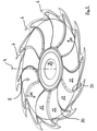
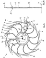
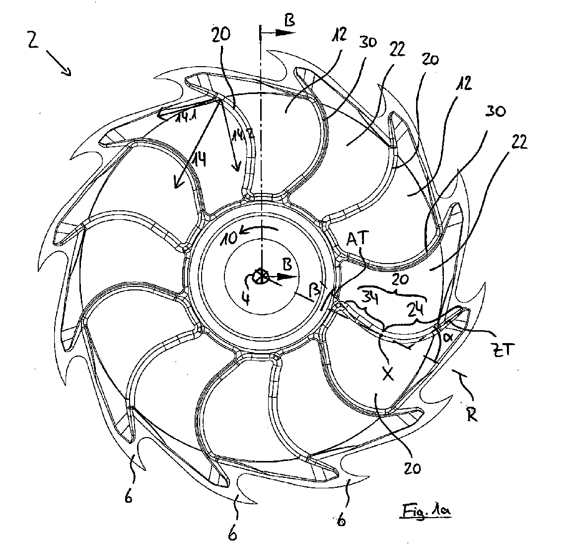
- the Fig. 1a and 4a 12 show different exemplary embodiments of a cutting device 2 according to the invention.
- the cutting device 2 is designed for cutting agricultural crops by a rotary movement about a cutting axis of rotation 4 .
- the cutting devices 2 shown comprise a plurality of knife elements 6, 16, which are designed to be open in a direction of rotation 10 in the plan views of the upper side 8 of the cutting devices 2.
- the blade elements 6, 16 are crescent-shaped in the plan views of the upper side 8 of the cutting devices 2.
- Both exemplary embodiments have radial conveying elements 12 which are arranged on the upper side 8 and are stationary relative to the blade elements 6 , 16 . Sections of the radial conveying elements are intended to convey the useful plants in a conveying direction 14 trained.
- the conveying direction 14 is aligned proportionally tangentially 14.1 relative to the cutting axis of rotation 4 and proportionally radially 14.2 to the cutting axis of rotation 4.
- Each of the radial conveying elements 12 shown is adjacent along a conveying contour 20 to an intermediate element 22 arranged upstream in the direction of circulation 10 .
- a feed section 24 of the feed contours 20 runs from a neutral feed point X proportionately in the direction of rotation 10 and proportionately in the radial direction away from the cutting axis of rotation 4 .
- the radial conveying elements 12 are raised by 6 mm in the axial direction relative to the adjoining intermediate elements 22 (cf. Fig. 1b and 4b ).
- a material thickness of the intermediate element 22 measured in the axial direction corresponds to a material thickness of the radial conveying element 12 measured in the axial direction and is 3 mm.
- the feed sections 24 are arcuate in plan view such that a feed angle ⁇ between a feed tangential ZT of the feed section 24 and a radial line R intersecting the neutral feed point X of the feed section 24 increases with increasing radius, i.e. distance from the cutting axis of rotation 4 (cf. Figure 3a and 6a ).
- the conveying contours 20 shown each have a discharge section 34, which runs proportionally counter to the direction of rotation 10 and proportionally in the radial direction away from the cutting axis of rotation 4 and forms a discharge angle ⁇ between a discharge tangential AT and the radial R.
- the discharge sections 34 are arranged between the cutting axis of rotation 4 and the respectively adjoining feed section 24 and adjoin one of the feed sections 24 at the neutral feed point X.
- a radial feed element 12 is assigned to every second of the blade elements 6, 16 (cf. in particular 2 and 5 ). However, it is also possible for every third, every fourth or every sixth blade element 6, 16 to be assigned a radial conveying element.
- Both exemplary embodiments of the cutting device 2 according to the invention are suitable both for assembly in a first assembly position (cf. 7 and 8th ) as well as to an assembly in a second assembly position in which the direction of rotation 10 is opposite to that in the first assembly position.
- first assembly position the upper side 8 designed as a first upper side is at least partially directed upwards.
- second mounting position a second top side 18 of the cutting device 2 opposite the first top side 8 is at least partially directed upwards.
- the intermediate elements 22 shown each adjoin along an intermediate contour 30 a further radial conveying element 12 arranged upstream in the direction of rotation 10 .
- the course of the intermediate contour 30 corresponds to the course of the conveying contour 20 .
- a conveying contour 20 is formed on the second top side 18 in the axial direction opposite the intermediate contour 30 of the first top side 8 .
- the second exemplary embodiment of the cutting device 2 has two different groups of knife elements 6, 16.
- the cutting edges of the knife elements 6 in a first group are offset in the axial direction relative to the cutting edges of the knife elements 16 in a second group (cf. Figure 4b , Figures 6b and 6c ).
- the blade elements 6, 16 of the different groups alternate in the direction of rotation 10.
- all blade elements 6 are arranged at the same average axial height (cf. Fig. 1b , 3b and 3c ).
- Both embodiments include between their cutting axis of rotation 4 and the radial conveyor and intermediate elements 12, 22 running in the direction of rotation 10 groove 32 in the Fig. 1b and 4b is shown.
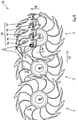
- FIG. 7 shows a harvesting attachment 40 according to the invention and only partially shown here with cutting devices 2 according to the first exemplary embodiment ( Figures 1a to 3c ).
- 8 shows another harvesting attachment 40 according to the invention and also partially shown with cutting devices 2 according to the second exemplary embodiment ( Figures 4a to 6c ).
- the in the 7 and 8th Cutting devices 2 shown are arranged in the same assembly position.
- the harvesting attachments 40 shown are designed for agricultural harvesting machines, in particular for harvesting corn or grain.
- the cutting devices 2 shown are rotatably mounted relative to a header frame, not shown.
- the cutting axes of rotation 4 of the cutting devices 2 are spaced apart from one another in a transverse direction 42 .
- the harvesting attachments 40 shown include a driver device 44 that rotates during operation and is only partially shown.
- the cutting devices 2 are proportionally arranged in front of the driver device 44 in a harvest travel direction 48 .
Landscapes
- Life Sciences & Earth Sciences (AREA)
- Environmental Sciences (AREA)
- Harvesting Machines For Specific Crops (AREA)
- Threshing Machine Elements (AREA)
- Harvester Elements (AREA)
Abstract
Description
- Die Erfindung betrifft eine Schneidvorrichtung, die zum Schneiden landwirtschaftlicher Nutzpflanzen durch eine Drehbewegung um eine Schneiddrehachse ausgebildet ist. Die Schneidvorrichtung umfasst zumindest ein Messerelement. Das Messerelement ist in einer Draufsicht auf eine Oberseite der Schneidvorrichtung in eine Umlaufrichtung geöffnet ausgebildet.
- Eine derartige Schneidvorrichtung ist bekannt aus der
EP 3 130 214 B1 . Die bekannte Schneidvorrichtung ist für ihren Betrieb an einer Erntemaschine zu montieren bzw. Teil davon. Im Betrieb rotiert die Schneidvorrichtung um die Schneidrehachse und wird in eine zur Schneiddrehachse angewinkelte Fortbewegungsrichtung auf die zu schneidenden Nutzpflanzen zubewegt. Dabei durchschneidet das zumindest eine Messerelement die Nutzpflanzen. - Nachteilig bei der bekannten Schneidvorrichtung ist, dass sich die geschnittenen Nutzpflanzen bei größeren Fortbewegungsgeschwindigkeiten auf der Oberseite der Schneidvorrichtung stauen und je nach Erntebedingungen in Fortbewegungsrichtung von der Schneidvorrichtung auf den Ackerboden fallen, was Ernteverluste verursacht.
- Weiterhin haben solche Schneidvorrichtungen einen hohen Querschnitt, damit sie ein ausreichendes Widerstandsmoment aufweisen, um sich im Betrieb nicht zu verformen. Das Verformen könnte dazu führen, dass sich benachbarte Schneidvorrichtungen berühren und gegenseitig zerstören. Aufgrund des hohen Querschnitts ist das Gewicht solcher Schneidvorrichtungen jedoch hoch, was einen verhältnismäßig hohen Verschleiß und auch bezüglich des Kraftstoffverbrauchs hohe Kosten verursacht.
- Aufgabe der vorliegenden Erfindung ist die Bereitstellung einer gattungsgemäßen Schneidvorrichtung sowie eines Erntevorsatzes und eines Feldhäckslers jeweils mit der Schneidvorrichtung, welche die vorbeschriebenen Nachteile vermeidet.
- Erfindungsgemäß wird die Aufgabe durch eine gattungsgemäße Schneidvorrichtung gelöst, die zumindest ein zumindest an der Oberseite angeordnetes und relativ zum Messerelement ortsfestes Radialförderelement aufweist. Das Radialförderelement ist zumindest abschnittsweise zu einer Förderung der Nutzpflanzen in eine Förderrichtung ausgebildet. Die Förderrichtung ist relativ zur Schneidrehachse anteilig tangential und anteilig radial zur Schneiddrehachse ausgerichtet. Die Förderrichtung ist insbesondere eine Resultierende aus einem tangential in die Umlaufrichtung gerichteten Förderrichtungsanteil und einem radial der Schneiddrehachse zugewandten Förderrichtungsanteil.
- Die Schneidvorrichtung ist insbesondere als Schneidscheibe oder als Schneidscheibensegment ausgebildet. Als Schneidscheibe hat die Schneidvorrichtung bevorzugt eine Bohrung, durch die die Schneiddrehachse hindurch verläuft und im Bereich derer die Schneidvorrichtung an einer Trag- bzw. Antriebsvorrichtung zu befestigen ist. Als Schneidscheibensegment ist die Schneidvorrichtung in der Draufsicht insbesondere durch zwei ungeachtet des Messerelementes im Wesentlichen in Umlaufrichtung verlaufende Konturen sowie zwei in radialer Richtung verlaufende Konturen umgrenzt. Die Schneidvorrichtung ist vorzugsweise einstückig ausgebildet.
- Die Schneidvorrichtung weist bevorzugt eine Mehrzahl von Messerelementen auf, die sich entlang eines Außenumfangs der Schneidvorrichtung bzw. in Umlaufrichtung aneinander anschließen. Das zumindest eine Messerelement bildet insbesondere eine Schneide aus. Aufgrund einer bevorzugten abschnittsweisen Sichelform läuft das Messerelement bevorzugt in Umlaufrichtung bzw. in tangentialer Richtung spitz zu. Eine rechtwinklig zu zumindest einem Teil der Schneide orientierte Schneidenorthogonale verläuft bevorzugt ausgehend von der Schneide von dem Messerelement weg und anteilig auf die Schneidrehachse zu. Die Schneide erstreckt sich mit wachsendem Radius in die Umlaufrichtung. Durch diese Ausbildung des Messerelements bzw. der Schneide wird verhindert, dass die geschnittenen Nutzpflanzen von der Schneidvorrichtung in die Fortbewegungsrichtung abgestoßen werden. Die bevorzugte Sichelform sorgt dafür, dass eine Druckkraft auf die Nutzpflanze beim Schneiden derer anteilig entgegen der Fortbewegungsrichtung wirkt. Dadurch gelangen die Nutzpflanzen erst zuverlässig auf die Oberseite und damit in den Wirkbereich des Radialförderelementes. Möglich ist es auch, dass die Schneidvorrichtung aus zahnförmigen Messerelementen gebildet ist, welche einen konstanten Winkel zur Radialen aufweisen.
- Das Radialförderelement ist insofern an der Oberseite angeordnet, als es in der Draufsicht auf die Oberseite sichtbar ist. Die Oberseite ist bevorzugt im Wesentlichen eben und dabei rechtwinklig zur Schneiddrehachse ausgebildet. Durch das Radialförderelement wird erreicht, dass im Betrieb die geschnittenen Nutzpflanzen bereits durch die rotierende Schneidvorrichtung zumindest anteilig auf die Schneiddrehachse zubewegt werden. Das Stauen von geschnittenen Nutzpflanzen auf der Schneidvorrichtung und eine dadurch bedingte Behinderung des weiteren Schneidens bzw. ein Verlust von Erntegut werden somit verhindert und insbesondere ein zügiger Gutfluss von den Messerelementen bis zu einem der Schneidvorrichtungen übergeordneten Mitnehmer, der nicht Teil der Erfindung ist, sichergestellt.
- Bevorzugt grenzt das Radialförderelement entlang einer Förderkontur an ein in die Umlaufrichtung vorgeordnetes Zwischenelement an. Ein Zuförderabschnitt der Förderkontur verläuft von einem Neutralförderpunkt X aus vorzugsweise anteilig in die Umlaufrichtung und anteilig in radialer Richtung von der Schneiddrehachse weg. Im Neutralförderpunkt verläuft die Förderkontur insbesondere ausschließlich in die radiale Richtung und/oder die Förderrichtung ausschließlich in die tangentiale Richtung. Der Neutralförderpunkt ist alternativ oder zusätzlich bevorzugt der Punkt des Zuförderabschnittes, der bezogen auf die Umlaufrichtung am weitesten hinten angeordnet ist. In der Draufsicht betrachtet verläuft insbesondere eine zu zumindest einem Teil der Förderkontur rechtwinklige Förderkonturorthogonale von der Förderkontur aus anteilig auf die Schneiddrehachse zu. Die Förderkonturorthogonale ist insbesondere parallel zur oder liegt in der Förderrichtung. Insbesondere ist sowohl das Zwischenelement als auch das Radialförderelement sowohl von der Schneiddrehachse als auch von einem Außenumfang der Schneidvorrichtung beabstandet. Besonders bevorzugt weist die Schneidvorrichtung eine Mehrzahl von Radialförderelementen und eine Mehrzahl von Zwischenelementen auf, die sich in Umlaufrichtung abwechselnd angeordnet sind. Die Förderkontur beschreibt in der Draufsicht denjenigen zumindest im Wesentlichen linienförmigen Grenzbereich zwischen dem zumindest einen Radialförderelement und dem zumindest einen Zwischenelement. Das Zwischenelement und/oder das Radialförderelement sind oberseitig und/oder auf der gegenüberliegenden Seite bevorzugt zumindest zu einem überwiegenden Teil eben ausgebildet, wobei dieser Teil sich bevorzugt orthogonal zu Schneiddrehachse erstreckt. Der Zuförderabschnitt der Förderkontur ist derjenige Teil der Förderkontur, der eine Förderung der geschnittenen Nutzpflanzen in die Förderrichtung bewirkt.
- Vorzugsweise ist das Radialförderelement zumindest bereichsweise relativ zum Zwischenelement in axialer Richtung um zumindest 1 mm, bevorzugt um zumindest 3 mm, besonders bevorzugt um zumindest 6 mm erhaben ausgebildet. Die axiale Richtung ist bezogen auf die Schneiddrehachse. Durch diese Ausbildung des Radialförderelementes wird im Zusammenhang mit dem schwerkraftbedingten Aufliegen der Nutzpflanzen auf der Oberseite eine besonders zuverlässige Förderung derer in die Förderrichtung erreicht.
- Der insbesondere den Höhenunterschied überbrückende Übergang vom Zwischenelement zum Radialförderelement ist bevorzugt fließend ausgebildet, so dass die Oberfläche der Schneidvorrichtung bei deren Rotation allmählich ansteigt. Nahe des Messerelementes nimmt der Höhenunterschied zwischen dem Zwischenelement und dem Radialförderelement mit zunehmendem Radius bevorzugt ab bzw. gehen beide bevorzugt in einen Bereich mittlerer Höhe über. Vorzugsweise ist das Messerelement in einer Ansicht der Schneidvorrichtung aus radialer Richtung zwischen einem oberen Teil des Radialförderelements und einem unteren Teil des Zwischenelementes angeordnet und befindet sich auf mittlerer Höhe. Insbesondere erstrecken sich einzig die Messerelemente bis zum Außenradius der Schneidvorrichtung. Durch diese Ausbildung der Schneidvorrichtung bzw. der Radialförderelemente kommt es zu einer optimalen Einwirkung derer auf die geschnittenen Nutzpflanzen, ohne dass die Funktion der Messerelemente beeinträchtigt wird.
- In einer vorteilhaften Ausgestaltung der Erfindung stimmt eine in die axiale Richtung gemessene Materialstärke des Zwischenelementes mit einer in die axiale Richtung gemessenen Materialstärke des Radialförderelementes zumindest im Wesentlichen überein. Bevorzugt stimmt auch eine in die axiale Richtung gemessene Materialstärke des Messerelementes damit zumindest im Wesentlichen überein. Die Materialstärke beträgt bevorzugt zwischen 1 mm und 10 mm, besonders bevorzugt zwischen 2 mm und 6 mm, insbesondere im Wesentlichen 3 mm. In einer bevorzugten Ausführungsform sind das Zwischenelement und/oder das Radialförderelement ausgehend von zumindest dem Bereich mittlerer Höhe der Schneidvorrichtung gesickte Bereiche der Schneidvorrichtung. Dadurch ist das Radialförderelement und/oder das Zwischenelement relativ zu dem Bereich mittlerer Höhe angehoben oder abgesenkt. Der Bereich mittlerer Höhe kann beispielsweise ein einen Innenradius der Schneidvorrichtung ausbildender Montagebereich der Schneidvorrichtung sein. Das Einbringen solcher Sicken ist beispielsweise, ausgehend von einem insbesondere aus einem Flachbandmaterial einstückig hergestellten ebenen Blech, durch eine Prägung möglich. Durch das Einbringen der Sicken erhöht sich das Widerstandsmoment der Schneidvorrichtung, so dass der Querschnitt der Schneidvorrichtung erheblich verringert sein kann. Dabei ist eine Reduktion des Querschnitts in einer Größenordnung von bis zu 40% im Vergleich zu herkömmlichen Schneidvorrichtungen erreichbar. Aufgrund des infolgedessen erheblich geringeren Gewichts der Schneidvorrichtung sind die Schnittkräfte und das Anlaufmoment verringert, so dass bei einer solche Schneidvorrichtungen antreibenden Erntemaschine eine deutliche Kraftstoffersparnis möglich ist. Hierdurch lässt sich das Radialförderelement sowie eine erhöhte Stabilität der Schneidvorrichtung mit nur minimalem Materialaufwand realisieren.
- Die Schneidvorrichtung weist bevorzugt zumindest eine insbesondere in dem Radialförderelement oder dem Zwischenelement angeordnete Montagebohrung auf, die sich parallel zur Schneiddrehachse durch das Material erstreckt. Insbesondere weist die Schneidvorrichtung zumindest zwei Paare von derartigen Montagebohrungen auf. Diese dienen der Anordnung von Werkzeugen an der Schneidvorrichtung, die einem Zerfransen der auf dem Acker verbleibenden, verwurzelten Pflanzenteile und/oder einen Entfernen von Ablagerungen oberhalb von Spitzenhaltern eines die Schneidvorrichtung insbesondere umfassenden Erntevorsatzes dienen.
- Vorzugsweise ist der Zuförderabschnitt in der Draufsicht derart bogenförmig ausgebildet, dass ein Zuförderwinkel α zwischen dem Zuförderabschnitt und einer den Neutralförderpunkt schneidenden Radialen mit wachsendem Radius zunimmt. Der Zuförderwinkel α wird insbesondere an einem Schnittpunkt der Radialen mit einer an dem Zuförderabschnitt anliegenden Zufördertangente gemessen und nimmt mit einer Entfernung des Berührungspunktes der Zufördertangente am Zuförderabschnitt von der Schneiddrehachse zu, wobei sich auch der Schnittpunkt der Radialen mit der Zufördertangente von der Schneiddrehachse entfernt. Der Zuförderwinkel α steigt bevorzugt nicht über 90° und variiert besonders bevorzugt über eine Winkelspanne von 0° bis 90°. Der Zuförderabschnitt verläuft bevorzugt mit wachsendem Abstand zur Schneiddrehachse mit einem wachsenden Anteil in die Umlaufrichtung. Durch diese Ausbildung des Zuförderabschnittes bzw. der Förderkontur lassen sich die geschnittenen Nutzpflanzen im Betrieb allmählich in die Förderrichtung beschleunigen und so letztlich eine möglichst umfangreiche Förderwirkung erreichen.
- In einer bevorzugten Ausgestaltung der Erfindung hat die Förderkontur einen Abförderabschnitt, der anteilig entgegen der Umlaufrichtung und anteilig in radialer Richtung von der Schneiddrehachse weg verläuft. Der Abförderabschnitt ist insbesondere zwischen der Schneiddrehachse und dem Zuförderabschnitt angeordnet. Insbesondere verläuft auch der Abförderabschnitt bogenförmig und/oder geht fließend in den Zuförderabschnitt über. Bevorzugt grenzen der Abförderabschnitt und der Zuförderabschnitt im Neutralförderpunkt aneinander. Bezogen auf die den Neutralförderpunkt schneidenden Radialen stellt der Neutralförderpunkt insbesondere einen Wendepunkt dar, an dem sich das Vorzeichen des Erstreckungsanteils der Förderkontur in die tangentiale Richtung umkehrt. Ein analog zum Zuförderwinkel α gemessener Abförderwinkel β variiert bevorzugt über eine Winkelspanne von 10° bis 30°. Der Abförderabschnitt reicht bis zu einem Radius, bis zu dem die geschnittenen Nutzpflanzen in radialer Richtung gefördert werden sollen, um von da vom Mitnehmer aufgenommen zu werden. Eine weitere Förderung der Nutzpflanzen, insbesondere von vom Mitnehmer regelmäßig nicht erfassten Lieschblättern der Nutzpflanzen, in Richtung der Schneiddrehachse führte zu einem Umwickeln einer Antriebsachse der Schneidvorrichtung, das den Betrieb der Schneidvorrichtung stört bzw. diese im Extremfall blockiert. Der Abförderabschnitt bewirkt eine Förderung zu nahe an die Schneiddrehachse gelangter Nutzpflanzenteile von der Schneiddrehachse weg, um diesen nachteiligen Effekt zu verhindern. Bevorzugt ist das Radialförderelement bzw. die Förderkontur zumindest abschnittsweise sichelförmig ausgebildet.
- Vorzugsweise umfasst die Schneidvorrichtung mehrere Messerelemente, wobei zumindest jedem vierten, insbesondere zumindest zwei Messerelementen ein Radialförderelement zugeordnet ist. Insbesondere ist genau jedem zweiten Messerelement ein Radialförderelement zugeordnet. Ein Zuförderabschnitt des zumindest einen Radialförderelementes verläuft bevorzugt auf das Messerelement, dem es zugeordnet ist, bzw. deren Schneide zu. Insbesondere bildet eine Schneide des jeweiligen Messerelementes eine Verlängerung der Bogenform der Förderkontur.
- In einer vorteilhaften Ausgestaltung der Erfindung ist die Schneidvorrichtung sowohl zu einer Montage in einer ersten Montageposition als auch zu einer Montage in einer zweiten Montageposition ausgebildet. In der ersten Montageposition ist die Oberseite, welche hier eine erste Oberseite bildet, zumindest anteilig nach oben gerichtet. In der zweiten Montageposition ist eine der ersten Oberseite gegenüberliegende zweite Oberseite der Schneidvorrichtung zumindest anteilig nach oben gerichtet. Die Positionierung der Schneiddrehachse ist in beiden Montagepositionen im Betrieb bevorzugt übereinstimmend. Durch die beiden Montagepositionen ist die Schneidvorrichtung insbesondere als Wechselschneidscheibe bzw. Wechselschneidscheibensegment ausgebildet, die bzw. das sich im Betrieb, ausgehend von der Trag- oder Antriebsvorrichtung betrachtet, an dem sie bzw. es anzuordnen sind, in beide Drehrichtungen betreiben lassen. Insbesondere lassen sich identisch ausgebildete, erfindungsgemäße Schneidvorrichtungen sowohl an der linken Hälfte des Erntevorsatzes als auch an der rechten Hälfte des Erntevorsatzes anordnen, wobei die linke Hälfte zu einer Förderung der geschnittenen Nutzpflanzen nach rechts und die rechte Hälfte zur Förderung der geschnittenen Nutzpflanzen nach links ausgebildet ist, um diese einem mittig angeordneten Erntegutkanal zuzuführen. Durch diese Ausbildung der erfindungsgemäßen Schneidvorrichtung hat diese bei Erhalt der durch die sichelförmigen Messerelemente und das Radialförderelement gegebenen Vorzüge den signifikanten Vorteil, dass es universal einsetzbar ist und vom Betreiber nicht unterschiedliche gattungsgemäße Schneidvorrichtungen als Ersatzteile für dieselbe Maschine vorgehalten werden müssen.
- Bevorzugt grenzt das Zwischenelement entlang einer Zwischenkontur an einen in die Umlaufrichtung vorgeordnetes weiteres Radialförderelement an. In der Draufsicht auf die (erste) Oberseite stimmt der Verlauf der Zwischenkontur insbesondere mit dem Verlauf der Förderkontur überein. Die Übereinstimmung ist dabei unabhängig vom Anstieg bzw. vom Absinken der Förderkontur in die Umlaufrichtung. Die Zwischenkontur ist insbesondere ebenso bogenförmig wie die Förderkontur ausgebildet und relativ zu letzterer vorzugsweise einzig um die Schneiddrehachse verschwenkt angeordnet.
- Besonders bevorzugt ist in axialer Richtung gegenüber von der Zwischenkontur an der ersten Oberseite eine Förderkontur an der zweiten Oberseite ausgebildet. Insbesondere bildet das in der ersten Montageposition gegebene Radialförderelement in der zweiten Montageposition ein Zwischenelement aus und bildet das in der ersten Montageposition gegebene Zwischenelement in der zweiten Montageposition ein Radialförderelement aus. Bevorzugt haben das Zwischenelement und das Radialförderelement (in einer der Montagepositionen) in der Draufsicht eine im Wesentlichen gleiche Form und sind insbesondere zumindest im Wesentlichen nierenförmig ausgebildet. Insbesondere haben das Zwischenelement und das Radialförderelement eine übereinstimmende tangentiale und/oder radiale Erstreckung.
- Bevorzugt ist zumindest ein Teil einer Schneide eines ersten Messerelementes relativ zu zumindest einem Teil einer Schneide eines in Umlaufrichtung benachbart angeordneten zweiten Messerelementes in axialer Richtung versetzt angeordnet. Insbesondere haben beide Messerelemente eine übereinstimmende in axialer Richtung gemessene Materialstärke, die vorzugsweise zwischen 1 mm und 6 mm, insbesondere 3 mm beträgt. In tangentialer Richtung betrachtet sind die Messerelemente insbesondere derart versetzt angeordnet, dass zwischen den beiden Messerelementen ein Freiraum bleibt. Dieser Freiraum hat insbesondere eine axiale Erstreckung von 3 mm. Im Betrieb wird jetzt die Nutzpflanze bevorzugt von einer Mehrzahl von Messerelementen jeweils teilweise geschnitten, wobei durch die vorbeschriebene Versetzung der Messerelemente eine Schnittbreite bzw. -höhe entsteht, die die Materialstärke der Schneidvorrichtung bzw. von deren Messerelementen übersteigt. Hierdurch wird unabhängig von der Montageposition vermieden, dass die zu fördernden Nutzpflanzen von dem Radialförderelement in die Fortbewegungsrichtung geschoben werden. Das Radialförderelement hat bevorzugt eine Höhe, die gleich oder höher als die Höhe der Messerelemente ist, jeweils in axialer Richtung gemessen. In dieser Ausbildung ist das Radialförderelement bevorzugt dem unteren Messerelement zugeordnet.
- Vorzugsweise ist zwischen der Schneiddrehachse und dem Radialförderelement eine in Umlaufrichtung umlaufende Nut angeordnet. Durch diese werden mechanische Spannungen innerhalb der Schneidvorrichtung reduziert und dadurch deren Ausfallsicherung erhöht.
- Die Aufgabe wird weiterhin gelöst durch einen Erntevorsatz für landwirtschaftliche Erntemaschinen, insbesondere zum Ernten von stängeligem Erntegut wie Mais oder Getreide. Der Erntevorsatz weist eine Mehrzahl drehbar gelagerter Schneidvorrichtungen wie vor- und/oder nachbeschrieben auf. Deren Schneiddrehachsen sind in eine Querrichtung voneinander beabstandet. Weiterhin weist der Erntevorsatz zumindest eine im Betrieb umlaufende Mitnehmervorrichtung mit zumindest im Betrieb oberhalb der Schneidvorrichtungen angeordneten Mitnehmerelementen zur Förderung der abgeschnittenen Nutzpflanzen in die Querrichtung auf. Die Schneiddrehachsen sind hierbei bevorzugt parallel zueinander angeordnet. Die Querrichtung ist insbesondere horizontal und rechtwinklig zu zumindest einer Schneiddrehachse orientiert. Mitnehmerdrehachsen, um die die Mitnehmervorrichtung bevorzugt umläuft, sind in einer Seitenansicht insbesondere höchstens geringfügig zu der zumindest einen Schneiddrehachse angewinkelt. Insbesondere weist der Erntevorsatz pro zu erntender Maisreihe genau eine Schneidvorrichtung oder genau zwei Schneidvorrichtungen auf. Das bedeutet insbesondere, dass die Schneiddrehachsen um zumindest im Wesentlichen 75 cm bzw. 37,5 cm voneinander beabstandet sind. Es ist auch denkbar, dass jeder Schneidvorrichtung eine koaxial zur Schneiddrehachse angeordnete rotierende Mitnehmervorrichtung zugeordnet ist. Mit diesem Erntevorsatz lassen sich die vorbeschriebenen Vorteile der erfindungsgemäßen Schneidvorrichtung bestmöglich im Betrieb umsetzen.
- Vorzugsweise ist die Förderkontur, insbesondere der Zuförderabschnitt, zumindest einer Schneidvorrichtung der Mitnehmervorrichtung in eine Erntefahrtrichtung, die insbesondere der Fortbewegungsrichtung gleicht, zumindest anteilig vorgeordnet. Bevorzugt erstreckt sich die Förderkontur bzw. der Zuförderabschnitt bis unter die Mitnehmerelemente. Die Mitnehmervorrichtung umfasst insbesondere eine im Betrieb umlaufende Gliederkette, deren Kettenglieder zumindest teilweise zumindest ein Mitnehmerelement aufweisen. Der Erntevorsatz umfasst insbesondere zumindest zwei derartiger Gliederketten. Zumindest ein Teil der Kettenglieder weist zumindest zwei übereinander angeordneter Mitnehmerelemente auf.
- Im Betrieb werden die Nutzpflanzen, nachdem sie geschnitten sind, vom Radialförderelement entgegen der Erntefahrtrichtung zur Mitnehmervorrichtung gefördert und von dieser anschließend in die Querrichtung abgefördert. Durch die zwei übereinander angeordneten Mitnehmerelemente ist die Abförderung besonders betriebssicher.
- Die Aufgabe wird weiterhin gelöst durch einen Feldhäcksler mit einem vor- und/oder nachbeschriebenen Erntevorsatz. Der Feldhäcksler hat insbesondere mehrere Antriebsräder und einen Motor.
- Weitere Einzelheiten und Vorteile der Erfindung sind den nachfolgend beschriebenen, schematisch dargestellten Ausführungsbeispielen zu entnehmen. Es zeigen
- Fig. 1a
- ein erstes Ausführungsbeispiel der erfindungsgemäßen Schneidvorrichtung in einer Draufsicht,
- Fig. 1b
- das erste Ausführungsbeispiel in einem teilweise dargestellten Querschnitt gemäß Hilfslinie B in
Fig. 1a , - Fig. 2
- das erste Ausführungsbeispiel in einer perspektivischen Ansicht,
- Fig. 3a
- das erste Ausführungsbeispiel in der Draufsicht,
- Fig. 3b
- das erste Ausführungsbeispiel in einem ersten Teilschnitt gemäß Hilfslinie B in
Fig. 3a , - Fig. 3c
- das erste Ausführungsbeispiel in einem zweiten Teilschnitt gemäß Hilfslinie C in
Fig. 3a , - Fig. 4a
- ein zweites Ausführungsbeispiel der erfindungsgemäßen Schneidvorrichtung in einer Draufsicht,
- Fig. 4b
- das zweite Ausführungsbeispiel in einem teilweise dargestellten Querschnitt gemäß Hilfslinie B in
Fig. 4a , - Fig. 5
- das zweite Ausführungsbeispiel in einer perspektivischen Ansicht,
- Fig. 6a
- das zweite Ausführungsbeispiel in der Draufsicht,
- Fig. 6b
- das zweite Ausführungsbeispiel in einem ersten Teilschnitt gemäß Hilfslinie B in
Fig. 6a , - Fig. 6c
- das zweite Ausführungsbeispiel in einem zweiten Teilschnitt gemäß Hilfslinie C in
Fig. 6a , - Fig. 7
- ein erstes Ausführungsbeispiel eines erfindungsgemäßen Erntevorsatzes in einer teilweise dargestellten Draufsicht,
- Fig. 8
- ein zweites Ausführungsbeispiel eines erfindungsgemäßen Erntevorsatzes in einer teilweise dargestellten Draufsicht.
- Die nachfolgend erläuterten Merkmale der erfindungsgemäßen Ausführungsbeispiele können auch einzeln oder in anderen Kombinationen als dargestellt oder beschrieben Gegenstand der Erfindung sein, stets aber zumindest in Kombination mit den Merkmalen des Anspruchs 1. Sofern sinnvoll sind funktional gleichwirkende Teile mit identischen Bezugsziffern versehen.
- Die
Fig. 1a und4a zeigen unterschiedliche Ausführungsbeispiele einer erfindungsgemäßen Schneidvorrichtung 2. In beiden Ausführungsbeispielen ist die Schneidvorrichtung 2 zum Schneiden landwirtschaftlicher Nutzpflanzen durch eine Drehbewegung um eine Schneiddrehachse 4 ausgebildet. Die dargestellten Schneidvorrichtungen 2 umfassen eine Mehrzahl von Messerelementen 6, 16, die in den Draufsichten auf die Oberseite 8 der Schneidvorrichtungen 2 in eine Umlaufrichtung 10 geöffnet ausgebildet sind. Zudem sind die Messerelemente 6, 16 in den Draufsichten auf die Oberseite 8 der Schneidvorrichtungen 2 sichelförmig ausgebildet. - Beide Ausführungsbeispiele weisen an der Oberseite 8 angeordnete und relativ zu den Messerelementen 6, 16 ortsfeste Radialförderelemente 12 auf. Die Radialförderelemente sind abschnittsweise zu einer Förderung der Nutzpflanzen in eine Förderrichtung 14 ausgebildet. Die Förderrichtung 14 ist relativ zur Schneiddrehachse 4 anteilig tangential 14.1 und anteilig radial 14.2 zur Schneiddrehachse 4 ausgerichtet.
- Jedes der gezeigten Radialförderelemente 12 grenzt entlang einer Förderkontur 20 an ein in die Umlaufrichtung 10 vorgeordnetes Zwischenelement 22 an. Ein Zuförderabschnitt 24 der Förderkonturen 20 verläuft von einem Neutralförderpunkt X aus anteilig in die Umlaufrichtung 10 und anteilig in radialer Richtung von der Schneiddrehachse 4 weg. Die Radialförderelemente 12 sind relativ zu den angrenzenden Zwischenelementen 22 in axialer Richtung um 6 mm erhaben ausgebildet (vgl.
Fig. 1b und4b ). Eine in die axiale Richtung gemessene Materialstärke des Zwischenelementes 22 stimmt mit einer in die axiale Richtung gemessenen Materialstärke des Radialförderelementes 12 überein und beträgt 3 mm. - Die Zuförderabschnitte 24 sind in den Draufsichten derart bogenförmig ausgebildet, dass ein Zuförderwinkel α zwischen einer Zufördertangentialen ZT des Zuförderabschnittes 24 und einer den Neutralförderpunkt X des Zuförderabschnittes 24 schneidenden Radialen R mit wachsendem Radius, d.h. Abstand zur Schneiddrehachse 4, zunimmt (vgl.
Fig. 3a und6a ). Die gezeigten Förderkonturen 20 haben neben dem Zuförderabschnitt 24 jeweils einen Abförderabschnitt 34, der anteilig entgegen der Umlaufrichtung 10 und anteilig in radialer Richtung von der Schneiddrehachse 4 weg verläuft und zwischen einer Abfördertangentialen AT und der Radialen R einen Abförderwinkel β bildet. Die Abförderabschnitte 34 sind zwischen der Schneiddrehachse 4 und dem jeweils anschließenden Zuförderabschnitt 24 angeordnet und grenzen im Neutralförderpunkt X an einen der Zuförderabschnitte 24. Jedem zweiten der Messerelemente 6, 16 ist ein Radialförderelement 12 zugeordnet (vgl. insbesondereFig. 2 und5 ). Es ist jedoch ebenso möglich, dass jedem dritten, jedem vierten oder jedem sechsten Messerelement 6, 16 ein Radialförderelement zugeordnet ist. - Beide Ausführungsbeispiele der erfindungsgemäßen Schneidvorrichtung 2 sind sowohl zu einer Montage in einer ersten Montageposition (vgl.
Fig. 7 und8 ) als auch zu einer Montage in einer zweiten Montageposition, in der die Umlaufrichtung 10 derjenigen in der ersten Montageposition entgegengesetzt ist, ausgebildet. In der ersten Montageposition ist die als eine erste Oberseite ausgebildete Oberseite 8 zumindest anteilig nach oben gerichtet. In der zweiten Montageposition ist eine der ersten Oberseite 8 gegenüberliegende zweite Oberseite 18 der Schneidvorrichtung 2 zumindest anteilig nach oben gerichtet. - Die gezeigten Zwischenelemente 22 grenzen jeweils entlang einer Zwischenkontur 30 an ein in die Umlaufrichtung 10 vorgeordnetes, weiteres Radialförderelement 12 an. In den Draufsichten auf die erste Oberseite 8 (vgl.
Fig. 1a ,3a ,4a ,6a ) stimmt der Verlauf der Zwischenkontur 30 mit dem Verlauf der Förderkontur 20 überein. In axialer Richtung gegenüber von der Zwischenkontur 30 der ersten Oberseite 8 ist eine Förderkontur 20 an der zweiten Oberseite 18 ausgebildet. - Das zweite Ausführungsbeispiel der Schneidvorrichtung 2 hat zwei unterschiedliche Gruppen von Messerelementen 6, 16. Die Schneiden der Messerelemente 6 einer ersten Gruppe sind relativ zu den Schneiden der Messerelemente 16 einer zweiten Gruppe in axialer Richtung versetzt angeordnet (vgl.
Fig. 4b ,Fig. 6b und Fig. 6c ). Dabei wechseln sich die Messerelemente 6, 16 der unterschiedlichen Gruppen in Umlaufrichtung 10 ab. Demgegenüber sind beim ersten Ausführungsbeispiel sämtliche Messerelemente 6 auf derselben, mittleren axialen Höhe angeordnet (vgl.Fig. 1b ,3b und 3c ). - Beide Ausführungsbeispiele umfassen zwischen ihrer Schneiddrehachse 4 und den Radialförder- und Zwischenelementen 12, 22 eine in die Umlaufrichtung 10 verlaufende Nut 32, die in den
Fig. 1b und4b dargestellt ist. -
Fig. 7 zeigt einen erfindungsgemäßen und hier nur teilweise dargestellten Erntevorsatz 40 mit Schneidvorrichtungen 2 gemäß dem ersten Ausführungsbeispiel (Fig. 1a bis 3c ).Fig. 8 zeigt einen weiteren erfindungsgemäßen und ebenso teilweise dargestellten Erntevorsatz 40 mit Schneidvorrichtungen 2 gemäß dem zweiten Ausführungsbeispiel (Fig. 4a bis 6c ). Die in denFig. 7 und8 dargestellten Schneidvorrichtungen 2 sind dabei in derselben Montageposition angeordnet. - Die gezeigten Erntevorsätze 40 sind für landwirtschaftliche Erntemaschinen, insbesondere zum Ernten von Mais oder Getreide ausgebildet. Die gezeigten Schneidvorrichtungen 2 sind drehbar relativ zu einem nicht gezeigten Erntevorsatzrahmen gelagert. Die Schneiddrehachsen 4 der Schneidvorrichtungen 2 sind in eine Querrichtung 42 voneinander beabstandet. Die gezeigten Erntevorsätze 40 umfassen eine im Betrieb umlaufende und nur teilweise dargestellte Mitnehmervorrichtung 44. Die Mitnehmervorrichtungen 44 weisen oberhalb der Schneidvorrichtungen 2 zwei angeordnete Mitnehmerelemente 46 zur Förderung der abgeschnittenen Nutzpflanzen in die Querrichtung 42 auf. Die Schneidvorrichtungen 2 sind der Mitnehmervorrichtung 44 in eine Erntefahrtrichtung 48 anteilig vorgeordnet.
Claims (16)
- Schneidvorrichtung (2), die zum Schneiden landwirtschaftlicher Nutzpflanzen durch eine Drehbewegung um eine Schneiddrehachse (4) ausgebildet ist und zumindest ein Messerelement (6, 16) umfasst, das in einer Draufsicht auf eine Oberseite (8) der Schneidvorrichtung (2) in eine Umlaufrichtung (10) geöffnet ausgebildet ist,
gekennzeichnet durch zumindest ein zumindest an der Oberseite (8) angeordnetes und relativ zum Messerelement (6, 16) ortsfestes Radialförderelement (12), das zumindest abschnittsweise zu einer Förderung der Nutzpflanzen in eine Förderrichtung (14) ausgebildet ist, die relativ zur Schneiddrehachse (4) anteilig tangential (14.1) und anteilig radial (14.2) zur Schneiddrehachse (4) ausgerichtet ist. - Schneidvorrichtung nach Anspruch 1, dadurch gekennzeichnet, dass das Radialförderelement (12) entlang einer Förderkontur (20) an ein in die Umlaufrichtung (10) vorgeordnetes Zwischenelement (22) angrenzt, wobei ein Zuförderabschnitt (24) der Förderkontur (20) von einem Neutralförderpunkt (X) aus anteilig in die Umlaufrichtung (10) und anteilig in radialer Richtung von der Schneiddrehachse (4) weg verläuft.
- Schneidvorrichtung nach einem der vorhergehenden Ansprüche, dadurch gekennzeichnet, dass das Radialförderelement (12) und/oder das Zwischenelement (22) ausgehend von zumindest einem Bereich mittlerer Höhe der Schneidvorrichtung (2) ein gesickter Bereich der Schneidvorrichtung (2) ist.
- Schneidvorrichtung nach einem der vorhergehenden Ansprüche, dadurch gekennzeichnet, dass eine in die axiale Richtung gemessene Materialstärke des Zwischenelementes (22) mit einer in die axiale Richtung gemessenen Materialstärke des Radialförderelementes (12) zumindest im Wesentlichen übereinstimmt.
- Schneidvorrichtung nach einem der vorhergehenden Ansprüche, dadurch gekennzeichnet, dass der Zuförderabschnitt (24) in der Draufsicht derart bogenförmig ausgebildet ist, dass ein Zuförderwinkel (a) zwischen einer den Neutralförderpunkt (X) schneidenden Radialen (R) und dem Zuförderabschnitt (24) mit wachsendem Radius zunimmt.
- Schneidvorrichtung nach einem der vorhergehenden Ansprüche, dadurch gekennzeichnet, dass ein Abförderabschnitt (34) der Förderkontur (20) anteilig entgegen der Umlaufrichtung (10) und anteilig in radialer Richtung von der Schneiddrehachse (4) wegverläuft und insbesondere zwischen der Schneiddrehachse (4) und dem Zuförderabschnitt (24) angeordnet ist.
- Schneidvorrichtung nach einem der vorhergehenden Ansprüche, dadurch gekennzeichnet, dass das Radialförderelement zumindest abschnittsweise sichelförmig ausgebildet ist.
- Schneidvorrichtung nach einem der vorhergehenden Ansprüche, gekennzeichnet durch mehrere Messerelemente (6, 16), wobei zumindest jedem vierten, bevorzugt jedem zweiten der Messerelemente (6, 16) ein Radialförderelement (12) zugeordnet ist.
- Schneidvorrichtung nach einem der vorhergehenden Ansprüche, gekennzeichnet durch eine Ausbildung sowohl zu einer Montage in einer ersten Montageposition, in der die als eine erste Oberseite ausgebildete Oberseite (8) zumindest anteilig nach oben gerichtet ist, als auch zu einer Montage in einer zweiten Montageposition, in der eine der ersten Oberseite (8) gegenüberliegende zweite Oberseite (18) der Schneidvorrichtung (2) zumindest anteilig nach oben gerichtet ist.
- Schneidvorrichtung nach einem der vorhergehenden Ansprüche, dadurch gekennzeichnet, dass das Zwischenelement (22) entlang einer Zwischenkontur (30) an ein in Umlaufrichtung (10) vorgeordnetes weiteres Radialförderelement (12) angrenzt, wobei in der Draufsicht auf die erste Oberseite (8) der Verlauf der Zwischenkontur (30) insbesondere mit dem Verlauf der Förderkontur (20) übereinstimmt.
- Schneidvorrichtung nach einem der vorhergehenden Ansprüche, dadurch gekennzeichnet, dass in axialer Richtung gegenüber von der Zwischenkontur (30) an der ersten Oberseite (8) eine Förderkontur (20) an der zweiten Oberseite (18) ausgebildet ist.
- Schneidvorrichtung nach einem der vorhergehenden Ansprüche, dadurch gekennzeichnet, dass zumindest ein Teil einer Schneide eines ersten Messerelementes (6) relativ zu zumindest einem Teil einer Schneide eines in Umlaufrichtung (10) benachbart angeordneten zweiten Messerelementes (16) in axialer Richtung versetzt angeordnet ist.
- Schneidvorrichtung nach einem der vorhergehenden Ansprüche, gekennzeichnet durch zumindest eine zwischen der Schneiddrehachse (4) und dem Radialförderelement (12) angeordnete und in Umlaufrichtung (10) umlaufende Nut (32).
- Erntevorsatz (40) für landwirtschaftliche Erntemaschinen, insbesondere zum Ernten von stängeligem Erntegut, aufweisend eine Mehrzahl drehbar gelagerter Schneidvorrichtungen (2) nach einem der vorhergehenden Ansprüche, deren Schneiddrehachsen (4) in eine Querrichtung (42) voneinander beabstandet sind, und zumindest eine im Betrieb umlaufende Mitnehmervorrichtung (44) mit oberhalb der Schneidvorrichtungen (2) angeordneten Mitnehmerelementen (46) zur Förderung der abgeschnittenen Nutzpflanzen in die Querrichtung (42).
- Erntevorsatz nach Anspruch 14, dadurch gekennzeichnet, dass die Förderkontur (20), insbesondere der Zuförderabschnitt (24), zumindest einer Schneidvorrichtung (2) der Mitnehmervorrichtung (44) in eine Erntefahrtrichtung (48) zumindest anteilig vorgeordnet ist und sich insbesondere bis unter die Mitnehmerelemente (46) erstreckt.
- Feldhäcksler mit einem Erntevorsatz nach Anspruch 14 oder 15.
Applications Claiming Priority (1)
| Application Number | Priority Date | Filing Date | Title |
|---|---|---|---|
| DE102020119368.8A DE102020119368B4 (de) | 2020-07-22 | 2020-07-22 | Schneidvorrichtung |
Publications (2)
| Publication Number | Publication Date |
|---|---|
| EP3942919A1 true EP3942919A1 (de) | 2022-01-26 |
| EP3942919B1 EP3942919B1 (de) | 2025-01-01 |
Family
ID=76920577
Family Applications (1)
| Application Number | Title | Priority Date | Filing Date |
|---|---|---|---|
| EP21185323.9A Active EP3942919B1 (de) | 2020-07-22 | 2021-07-13 | Schneidvorrichtung |
Country Status (4)
| Country | Link |
|---|---|
| US (1) | US12329061B2 (de) |
| EP (1) | EP3942919B1 (de) |
| DE (1) | DE102020119368B4 (de) |
| HU (1) | HUE070937T2 (de) |
Cited By (3)
| Publication number | Priority date | Publication date | Assignee | Title |
|---|---|---|---|---|
| US12329061B2 (en) * | 2020-07-22 | 2025-06-17 | Maschinenfabrik Bernard Krone GmbH & Co. KG | Cutting device |
| EP4591697A1 (de) | 2024-01-29 | 2025-07-30 | CLAAS Saulgau GmbH | Mähorgan eines mähwerks |
| EP4591696A1 (de) | 2024-01-29 | 2025-07-30 | CLAAS Saulgau GmbH | Mähwerk |
Families Citing this family (1)
| Publication number | Priority date | Publication date | Assignee | Title |
|---|---|---|---|---|
| USD1058322S1 (en) * | 2022-05-09 | 2025-01-21 | Shine Yen Industrial Co., Ltd. | Grass cutting blade |
Citations (4)
| Publication number | Priority date | Publication date | Assignee | Title |
|---|---|---|---|---|
| DE4109064A1 (de) * | 1991-03-20 | 1992-09-24 | Claas Saulgau Gmbh | Maiserntegeraet |
| DE19639805A1 (de) * | 1995-11-27 | 1997-05-28 | Claas Saulgau Gmbh | Mäh- und Fördervorrichtung für stengeliges Erntegut |
| DE10103595C1 (de) * | 2001-01-26 | 2002-06-20 | Case Harvesting Sys Gmbh | Schneid-und Fördervorrichtung für ein reihenunabhängig arbeitendes Schneidwek |
| EP3130214B1 (de) | 2015-08-12 | 2020-02-26 | Maschinenfabrik Bernard Krone GmbH & Co. KG | Mäh- und fördergerät zum ernten von stängeligem erntegut |
Family Cites Families (76)
| Publication number | Priority date | Publication date | Assignee | Title |
|---|---|---|---|---|
| US2115265A (en) * | 1936-01-24 | 1938-04-26 | Jennett Robert | Rotary hedge cutter |
| US2321387A (en) * | 1940-01-03 | 1943-06-08 | Kermit J Jackson | Pineapple harvester |
| US2527472A (en) * | 1945-01-18 | 1950-10-24 | Raymond H Wolf | Lawn mower |
| US2917826A (en) * | 1957-11-27 | 1959-12-22 | Pohr Jack | Cutter and trimmer blade |
| US3014333A (en) * | 1959-06-01 | 1961-12-26 | Palmer Fultz | Cutter for rotary lawnmower |
| US3078573A (en) * | 1962-03-12 | 1963-02-26 | Kern Paul Ervin | Disk type cutter |
| FI44174B (de) * | 1965-03-26 | 1971-06-01 | Outboard Marine Corp | |
| US3482380A (en) * | 1965-08-27 | 1969-12-09 | Eugene V Stair | Mower cutting device |
| GB1515268A (en) * | 1974-04-24 | 1978-06-21 | Clayson Nv | Rotary mowers |
| US4129977A (en) * | 1974-08-02 | 1978-12-19 | The Toro Company | Low speed rotary mower |
| US4019308A (en) * | 1974-12-27 | 1977-04-26 | Massey-Ferguson Services N.V. | Base cutting apparatus for sugar cane harvesters |
| US4083166A (en) * | 1976-10-20 | 1978-04-11 | Walter Russel Betenbaugh, Jr. | Mulcher attachment for rotary power mower |
| FR2382842A1 (fr) * | 1977-03-08 | 1978-10-06 | Vejux Michel | Barre de coupe pour la recolte des vegetaux |
| US4189903A (en) * | 1978-06-23 | 1980-02-26 | Mcdonough Power Equipment, Division Of Fuqua Industries, Inc. | Rotary lawn mower with removable mulching attachment |
| US4369618A (en) * | 1981-08-27 | 1983-01-25 | Dell Joseph C | Safety-vac lawn mower blade |
| DE3324102A1 (de) * | 1983-07-05 | 1985-01-17 | Claas Saulgau GmbH, 7968 Saulgau | Erntevorrichtung fuer in reihen stehende halmfruechte, wie mais |
| US4550554A (en) * | 1984-01-03 | 1985-11-05 | Ezra C. Lundahl, Inc. | Crop processor |
| GB2186779B (en) * | 1984-01-03 | 1988-09-28 | Lundahl Inc Ezra C | Crop processor |
| NL8502803A (nl) * | 1985-10-14 | 1987-05-04 | Lely Nv C Van Der | Inrichting en werkwijze voor het maaien van te velde staand gewas. |
| AU1554692A (en) * | 1991-04-09 | 1992-11-17 | Alexander Jan Vogelenzang | Cutting device for a rotary mower |
| DE4111981A1 (de) * | 1991-04-12 | 1992-10-15 | Kemper Gmbh Maschf | Maschine zum maehen und haeckseln von mais und dgl. stengelartigem erntegut |
| WO1993022897A1 (en) * | 1992-05-15 | 1993-11-25 | Hartley Blades Pty. Ltd. | Cutting disk |
| GB2283400B (en) * | 1992-05-29 | 1996-08-14 | James George Rolfe | A cutter |
| DE19535453A1 (de) * | 1994-11-18 | 1997-03-27 | Claas Saulgau Gmbh | Schneid- und Förderwerk für stengelige Erntegüter |
| DE19628195B4 (de) * | 1996-07-12 | 2004-04-29 | Claas Saulgau Gmbh | Schneid- und Fördervorrichtung für stängeliges Halmgut |
| AUPO359796A0 (en) * | 1996-11-12 | 1996-12-05 | Bird, Ronald George | Cutter apparatus |
| DE19734747B4 (de) * | 1997-08-12 | 2005-02-03 | Claas Saulgau Gmbh | Maisernte-Vorsatz zum Anbau an eine selbstfahrende Erntemaschine |
| DE10026495A1 (de) * | 2000-05-27 | 2001-11-29 | Kemper Gmbh Maschf | Erntegerät |
| DE10037534A1 (de) * | 2000-08-01 | 2002-02-14 | Kemper Gmbh Maschf | Maschine zum Mähen von stängelartigem Erntegut |
| FR2830167B1 (fr) * | 2001-10-03 | 2004-07-30 | Kuhn Sa | Machine agricole, notamment du type faucheuse rotative, comportant un dispositif de coupe ameliore |
| DE10151849A1 (de) * | 2001-10-24 | 2003-05-15 | Claas Saulgau Gmbh | Schwenkvorrichtung für ein mehrteiliges Erntevorsatzgerät |
| DE50206637D1 (de) * | 2001-10-26 | 2006-06-08 | Kemper Gmbh Maschf | Maschine zum Mähen von stängelartigem Erntegut |
| FR2840765B1 (fr) * | 2002-06-14 | 2005-02-04 | Kuhn Sa | Dispositif de coupe d'une faucheuse rotative comportant une fixation amelioree d'un organe de coupe |
| DE10330669A1 (de) * | 2003-07-08 | 2005-02-17 | Maschinenfabrik Kemper Gmbh & Co. Kg | Maschine zum Mähen von stängelartigem Erntegut |
| DE10351858B4 (de) * | 2003-11-06 | 2010-04-22 | Maschinenfabrik Kemper Gmbh & Co. Kg | Maschine zum Mähen von stängelartigem Erntegut |
| EP1543714B1 (de) * | 2003-12-17 | 2011-05-25 | CLAAS Saulgau GmbH | Gerät zum Ernten von Mais |
| DE102006020792B4 (de) * | 2006-05-03 | 2024-01-18 | Claas Saulgau Gmbh | Vorsatzgerät zum Ernten von stängeligem Erntegut |
| DE102006025455A1 (de) * | 2006-05-30 | 2007-12-20 | Claas Saulgau Gmbh | Vorsatzgerät zum Ernten von stängeligem Erntegut |
| DE102006053772A1 (de) * | 2006-11-15 | 2008-06-12 | Maschinenfabrik Kemper Gmbh & Co. Kg | Maschine zum Mähen von stängelartigem Erntegut |
| DE102007017911B4 (de) * | 2007-04-13 | 2009-01-02 | Maschinenfabrik Bernard Krone Gmbh | Landwirtschaftliche Erntemaschine |
| NL1035035C2 (nl) * | 2008-02-18 | 2009-08-19 | Lely Patent Nv | Maai-inrichting. |
| DE102008035191A1 (de) * | 2008-07-28 | 2010-02-04 | Claas Saulgau Gmbh | Vorsatzgerät zum Ernten von stängeligem Erntegut |
| DE102009051053A1 (de) * | 2009-05-28 | 2010-12-02 | Claas Selbstfahrende Erntemaschinen Gmbh | Vorsatzgerät zum Ernten stängelförmiger Pflanzen |
| US8056307B2 (en) * | 2009-10-05 | 2011-11-15 | Cnh America Llc | Mower cutterbar |
| DE102011118322A1 (de) * | 2011-11-11 | 2013-05-16 | Franz Schrattenecker | Pflückvorrichtung für Mais oder dergleichen |
| US8806844B2 (en) * | 2012-02-24 | 2014-08-19 | Dom, L.L.C. | Flail motor head attachment |
| FR2997262B1 (fr) * | 2012-10-31 | 2015-05-15 | Kuhn Audureau Sa | Machine de coupe comportant un outil de coupe perfectionne |
| DE102013004858B4 (de) * | 2013-03-21 | 2019-02-21 | Carl Geringhoff Gmbh & Co. Kg | Mäh- und Einzugseinrichtung zum Schneiden und Abfördern von stängeligem Erntegut |
| DE102013209466A1 (de) * | 2013-05-22 | 2014-11-27 | Maschinenfabrik Kemper Gmbh & Co. Kg | Maschine zum Mähen von stängelartigem Erntegut |
| DE102013209730A1 (de) * | 2013-05-24 | 2014-11-27 | Claas Saulgau Gmbh | Fördereinrichtung |
| BR102013019208A2 (pt) * | 2013-07-29 | 2015-11-10 | Marchesan Implementos E Máquinas Agrícolas Tatú S A | cortador e conjunto de corte de base |
| DE102014102391A1 (de) * | 2014-02-25 | 2015-08-27 | Claas Saulgau Gmbh | Schneidwerk für eine Erntemaschine |
| DE102014104304A1 (de) * | 2014-03-27 | 2015-10-01 | Claas Selbstfahrende Erntemaschinen Gmbh | Vorsatzgerät für einen selbstfahrenden Mähdrescher zum Ernten von Mais |
| DE102015206845B4 (de) * | 2015-04-16 | 2024-08-22 | Maschinenfabrik Kemper Gmbh & Co. Kg | Schneidwerk zur Ganzpflanzenernte |
| DE102015115100A1 (de) * | 2015-09-08 | 2017-03-09 | Carl Geringhoff Gmbh & Co. Kg | Vorrichtung zur Ernte von stängeligem Halmgut |
| JP6632473B2 (ja) * | 2016-06-02 | 2020-01-22 | 株式会社クボタ | コンバイン |
| CA2937639C (en) * | 2016-07-29 | 2026-04-14 | Honey Bee Manufacturing Ltd. | Header cutting system |
| DE102016214324A1 (de) * | 2016-08-03 | 2018-02-08 | Deere & Company | Erntevorsatz mit einem Mulchgerät zur Bearbeitung von auf einem Feld stehenden Pflanzenstümpfen |
| DE102016214323A1 (de) * | 2016-08-03 | 2018-02-08 | Deere & Company | Mulcheinrichtung zur mechanischen Bearbeitung von Pflanzenstoppeln |
| CN106472002B (zh) * | 2016-12-05 | 2019-07-16 | 中国农业科学院麻类研究所 | 一种切割装置及其应用 |
| CN108200796A (zh) * | 2016-12-16 | 2018-06-26 | 新昌县远轴工业设计有限公司 | 一种园林割草机刀盘 |
| DE102017206034B4 (de) * | 2017-04-07 | 2026-02-05 | Deere & Company | Maschine zur Ernte stängelartiger Pflanzen |
| BR202017011521U2 (pt) * | 2017-05-31 | 2018-12-18 | Sergio Lorenzato | sistema de discos rotativos com facas de corte dupl as com pontas angulares |
| CN108377715A (zh) * | 2018-05-04 | 2018-08-10 | 浙江中坚科技股份有限公司 | 一种新型刀盘 |
| US10945371B2 (en) * | 2018-06-05 | 2021-03-16 | Cnh Industrial America Llc | Adjustable stalk stomper/chopper curtain assembly |
| CN109362324A (zh) * | 2018-11-19 | 2019-02-22 | 朱季华 | 甘蔗根切刀盘 |
| DE102019113350B4 (de) * | 2019-05-20 | 2024-12-12 | Claas Saulgau Gmbh | Vorsatzgerät eines landwirtschaftlichen Erntefahrzeugs |
| CN112335396B (zh) * | 2019-08-07 | 2025-04-04 | 宝时得科技(中国)有限公司 | 割草机 |
| CN120570137A (zh) * | 2019-11-07 | 2025-09-02 | 苏州宝时得电动工具有限公司 | 割草机 |
| CN110692354A (zh) * | 2019-11-20 | 2020-01-17 | 诸暨市诺达机械科技有限公司 | 一种农用玉米收割机 |
| CN110999623A (zh) * | 2019-12-12 | 2020-04-14 | 乐清市易扬服饰有限公司 | 一种用于防止刀片卷刃的园林割草机 |
| DE102019220330A1 (de) * | 2019-12-20 | 2021-06-24 | Robert Bosch Gesellschaft mit beschränkter Haftung | Rasenmäher |
| DE102019220325A1 (de) * | 2019-12-20 | 2021-06-24 | Robert Bosch Gesellschaft mit beschränkter Haftung | Rasenmäher |
| US20210251144A1 (en) * | 2020-02-18 | 2021-08-19 | M & R Rickards Pty Ltd | Crop harvesting blade system |
| DE102020119368B4 (de) * | 2020-07-22 | 2024-10-24 | Maschinenfabrik Bernard Krone GmbH & Co. KG | Schneidvorrichtung |
| CN113973572A (zh) * | 2021-10-08 | 2022-01-28 | 中国农业机械化科学研究院呼和浩特分院有限公司 | 一种组合盘式旋转切割装置 |
-
2020
- 2020-07-22 DE DE102020119368.8A patent/DE102020119368B4/de active Active
-
2021
- 2021-07-13 HU HUE21185323A patent/HUE070937T2/hu unknown
- 2021-07-13 EP EP21185323.9A patent/EP3942919B1/de active Active
- 2021-07-20 US US17/380,503 patent/US12329061B2/en active Active
Patent Citations (4)
| Publication number | Priority date | Publication date | Assignee | Title |
|---|---|---|---|---|
| DE4109064A1 (de) * | 1991-03-20 | 1992-09-24 | Claas Saulgau Gmbh | Maiserntegeraet |
| DE19639805A1 (de) * | 1995-11-27 | 1997-05-28 | Claas Saulgau Gmbh | Mäh- und Fördervorrichtung für stengeliges Erntegut |
| DE10103595C1 (de) * | 2001-01-26 | 2002-06-20 | Case Harvesting Sys Gmbh | Schneid-und Fördervorrichtung für ein reihenunabhängig arbeitendes Schneidwek |
| EP3130214B1 (de) | 2015-08-12 | 2020-02-26 | Maschinenfabrik Bernard Krone GmbH & Co. KG | Mäh- und fördergerät zum ernten von stängeligem erntegut |
Cited By (5)
| Publication number | Priority date | Publication date | Assignee | Title |
|---|---|---|---|---|
| US12329061B2 (en) * | 2020-07-22 | 2025-06-17 | Maschinenfabrik Bernard Krone GmbH & Co. KG | Cutting device |
| EP4591697A1 (de) | 2024-01-29 | 2025-07-30 | CLAAS Saulgau GmbH | Mähorgan eines mähwerks |
| EP4591696A1 (de) | 2024-01-29 | 2025-07-30 | CLAAS Saulgau GmbH | Mähwerk |
| DE102024102486A1 (de) * | 2024-01-29 | 2025-07-31 | Claas Saulgau Gmbh | Mähwerk |
| DE102024102487A1 (de) * | 2024-01-29 | 2025-07-31 | Claas Saulgau Gmbh | Mähorgan eines Mähwerks |
Also Published As
| Publication number | Publication date |
|---|---|
| DE102020119368B4 (de) | 2024-10-24 |
| US12329061B2 (en) | 2025-06-17 |
| HUE070937T2 (hu) | 2025-07-28 |
| US20220022372A1 (en) | 2022-01-27 |
| EP3942919B1 (de) | 2025-01-01 |
| DE102020119368A1 (de) | 2022-01-27 |
Similar Documents
| Publication | Publication Date | Title |
|---|---|---|
| EP3942919B1 (de) | Schneidvorrichtung | |
| EP0760200B1 (de) | Maschine zum reihenunabhängigen Mähen und Häckseln von Mais und dgl. stengelartigem Erntegut | |
| EP0891693B1 (de) | Mähscheibe und Mähwerk | |
| DE2424377C2 (de) | Mäh- und Konditioniermaschine | |
| EP1199919B1 (de) | Erntegerät für stengelartiges erntegut | |
| AT390162B (de) | Maehbalken mit um annaehernd senkrechte achsen umlaufenden scheiben | |
| DE2848451A1 (de) | Reihenschneid-anbaugeraet | |
| EP4233517B1 (de) | Schneidscheibe für eine maschine zur ernte stängelartiger pflanzen | |
| EP3973765B1 (de) | Mähwerk mit walzenaufbereiter | |
| DE3017856C2 (de) | ||
| EP0504639A1 (de) | Maiserntegerät | |
| EP4118949B1 (de) | Aufnahmevorrichtung für eine erntemaschine | |
| EP0472102B1 (de) | Vertikutierer mit auf einer Messerwelle befestigten Messerscheiben | |
| DE102018121273A1 (de) | Aufnahmevorrichtung für eine Erntemaschine mit Stützelementen für die Abstreifer der Aufnahmevorrichtung | |
| DE19802672C2 (de) | Mähdrescher | |
| EP2810547B1 (de) | Messer für ein Sichelmähwerk und Sichelmähwerk | |
| EP1306003A1 (de) | Ballenpresse für landwirtschaftliches Erntegut | |
| EP1040746A1 (de) | Vorrichtung zum Pflücken von Fruchtständen | |
| EP1000533A1 (de) | Pflückvorrichtung zum Ernten von Halmfrüchten | |
| EP1247443B1 (de) | Häckseleinrichtung | |
| DE19639805C2 (de) | Mäh- und Fördervorrichtung für stengeliges Erntegut | |
| DE102019113350B4 (de) | Vorsatzgerät eines landwirtschaftlichen Erntefahrzeugs | |
| DE19544182B4 (de) | Landwirtschaftliches Gerät zur Ernte von stengeligem Halmgut | |
| DE1915534C3 (de) | Rasenmäher | |
| DE10234814A1 (de) | Schneidvorrichtung für Pflanzen |
Legal Events
| Date | Code | Title | Description |
|---|---|---|---|
| PUAI | Public reference made under article 153(3) epc to a published international application that has entered the european phase |
Free format text: ORIGINAL CODE: 0009012 |
|
| STAA | Information on the status of an ep patent application or granted ep patent |
Free format text: STATUS: THE APPLICATION HAS BEEN PUBLISHED |
|
| AK | Designated contracting states |
Kind code of ref document: A1 Designated state(s): AL AT BE BG CH CY CZ DE DK EE ES FI FR GB GR HR HU IE IS IT LI LT LU LV MC MK MT NL NO PL PT RO RS SE SI SK SM TR |
|
| STAA | Information on the status of an ep patent application or granted ep patent |
Free format text: STATUS: REQUEST FOR EXAMINATION WAS MADE |
|
| 17P | Request for examination filed |
Effective date: 20220624 |
|
| RBV | Designated contracting states (corrected) |
Designated state(s): AL AT BE BG CH CY CZ DE DK EE ES FI FR GB GR HR HU IE IS IT LI LT LU LV MC MK MT NL NO PL PT RO RS SE SI SK SM TR |
|
| P01 | Opt-out of the competence of the unified patent court (upc) registered |
Effective date: 20230517 |
|
| GRAP | Despatch of communication of intention to grant a patent |
Free format text: ORIGINAL CODE: EPIDOSNIGR1 |
|
| STAA | Information on the status of an ep patent application or granted ep patent |
Free format text: STATUS: GRANT OF PATENT IS INTENDED |
|
| RIC1 | Information provided on ipc code assigned before grant |
Ipc: A01D 45/02 20060101ALI20240724BHEP Ipc: A01D 43/08 20060101ALI20240724BHEP Ipc: A01D 41/14 20060101AFI20240724BHEP |
|
| INTG | Intention to grant announced |
Effective date: 20240821 |
|
| GRAS | Grant fee paid |
Free format text: ORIGINAL CODE: EPIDOSNIGR3 |
|
| GRAA | (expected) grant |
Free format text: ORIGINAL CODE: 0009210 |
|
| STAA | Information on the status of an ep patent application or granted ep patent |
Free format text: STATUS: THE PATENT HAS BEEN GRANTED |
|
| AK | Designated contracting states |
Kind code of ref document: B1 Designated state(s): AL AT BE BG CH CY CZ DE DK EE ES FI FR GB GR HR HU IE IS IT LI LT LU LV MC MK MT NL NO PL PT RO RS SE SI SK SM TR |
|
| REG | Reference to a national code |
Ref country code: GB Ref legal event code: FG4D Free format text: NOT ENGLISH |
|
| REG | Reference to a national code |
Ref country code: CH Ref legal event code: EP |
|
| REG | Reference to a national code |
Ref country code: DE Ref legal event code: R096 Ref document number: 502021006248 Country of ref document: DE |
|
| REG | Reference to a national code |
Ref country code: IE Ref legal event code: FG4D Free format text: LANGUAGE OF EP DOCUMENT: GERMAN |
|
| REG | Reference to a national code |
Ref country code: NL Ref legal event code: FP |
|
| REG | Reference to a national code |
Ref country code: LT Ref legal event code: MG9D |
|
| PG25 | Lapsed in a contracting state [announced via postgrant information from national office to epo] |
Ref country code: FI Free format text: LAPSE BECAUSE OF FAILURE TO SUBMIT A TRANSLATION OF THE DESCRIPTION OR TO PAY THE FEE WITHIN THE PRESCRIBED TIME-LIMIT Effective date: 20250101 |
|
| PG25 | Lapsed in a contracting state [announced via postgrant information from national office to epo] |
Ref country code: PL Free format text: LAPSE BECAUSE OF FAILURE TO SUBMIT A TRANSLATION OF THE DESCRIPTION OR TO PAY THE FEE WITHIN THE PRESCRIBED TIME-LIMIT Effective date: 20250101 |
|
| PG25 | Lapsed in a contracting state [announced via postgrant information from national office to epo] |
Ref country code: ES Free format text: LAPSE BECAUSE OF FAILURE TO SUBMIT A TRANSLATION OF THE DESCRIPTION OR TO PAY THE FEE WITHIN THE PRESCRIBED TIME-LIMIT Effective date: 20250101 |
|
| PG25 | Lapsed in a contracting state [announced via postgrant information from national office to epo] |
Ref country code: IS Free format text: LAPSE BECAUSE OF FAILURE TO SUBMIT A TRANSLATION OF THE DESCRIPTION OR TO PAY THE FEE WITHIN THE PRESCRIBED TIME-LIMIT Effective date: 20250501 Ref country code: NO Free format text: LAPSE BECAUSE OF FAILURE TO SUBMIT A TRANSLATION OF THE DESCRIPTION OR TO PAY THE FEE WITHIN THE PRESCRIBED TIME-LIMIT Effective date: 20250401 |
|
| PG25 | Lapsed in a contracting state [announced via postgrant information from national office to epo] |
Ref country code: HR Free format text: LAPSE BECAUSE OF FAILURE TO SUBMIT A TRANSLATION OF THE DESCRIPTION OR TO PAY THE FEE WITHIN THE PRESCRIBED TIME-LIMIT Effective date: 20250101 |
|
| PG25 | Lapsed in a contracting state [announced via postgrant information from national office to epo] |
Ref country code: PT Free format text: LAPSE BECAUSE OF FAILURE TO SUBMIT A TRANSLATION OF THE DESCRIPTION OR TO PAY THE FEE WITHIN THE PRESCRIBED TIME-LIMIT Effective date: 20250502 Ref country code: LV Free format text: LAPSE BECAUSE OF FAILURE TO SUBMIT A TRANSLATION OF THE DESCRIPTION OR TO PAY THE FEE WITHIN THE PRESCRIBED TIME-LIMIT Effective date: 20250101 |
|
| PG25 | Lapsed in a contracting state [announced via postgrant information from national office to epo] |
Ref country code: GR Free format text: LAPSE BECAUSE OF FAILURE TO SUBMIT A TRANSLATION OF THE DESCRIPTION OR TO PAY THE FEE WITHIN THE PRESCRIBED TIME-LIMIT Effective date: 20250402 Ref country code: BG Free format text: LAPSE BECAUSE OF FAILURE TO SUBMIT A TRANSLATION OF THE DESCRIPTION OR TO PAY THE FEE WITHIN THE PRESCRIBED TIME-LIMIT Effective date: 20250101 |
|
| PG25 | Lapsed in a contracting state [announced via postgrant information from national office to epo] |
Ref country code: CZ Free format text: LAPSE BECAUSE OF FAILURE TO SUBMIT A TRANSLATION OF THE DESCRIPTION OR TO PAY THE FEE WITHIN THE PRESCRIBED TIME-LIMIT Effective date: 20250101 |
|
| REG | Reference to a national code |
Ref country code: HU Ref legal event code: AG4A Ref document number: E070937 Country of ref document: HU |
|
| PGFP | Annual fee paid to national office [announced via postgrant information from national office to epo] |
Ref country code: NL Payment date: 20250723 Year of fee payment: 5 |
|
| PG25 | Lapsed in a contracting state [announced via postgrant information from national office to epo] |
Ref country code: SE Free format text: LAPSE BECAUSE OF FAILURE TO SUBMIT A TRANSLATION OF THE DESCRIPTION OR TO PAY THE FEE WITHIN THE PRESCRIBED TIME-LIMIT Effective date: 20250101 |
|
| PGFP | Annual fee paid to national office [announced via postgrant information from national office to epo] |
Ref country code: HU Payment date: 20250703 Year of fee payment: 5 |
|
| REG | Reference to a national code |
Ref country code: DE Ref legal event code: R097 Ref document number: 502021006248 Country of ref document: DE |
|
| PG25 | Lapsed in a contracting state [announced via postgrant information from national office to epo] |
Ref country code: SM Free format text: LAPSE BECAUSE OF FAILURE TO SUBMIT A TRANSLATION OF THE DESCRIPTION OR TO PAY THE FEE WITHIN THE PRESCRIBED TIME-LIMIT Effective date: 20250101 |
|
| PG25 | Lapsed in a contracting state [announced via postgrant information from national office to epo] |
Ref country code: DK Free format text: LAPSE BECAUSE OF FAILURE TO SUBMIT A TRANSLATION OF THE DESCRIPTION OR TO PAY THE FEE WITHIN THE PRESCRIBED TIME-LIMIT Effective date: 20250101 |
|
| PGFP | Annual fee paid to national office [announced via postgrant information from national office to epo] |
Ref country code: DE Payment date: 20250722 Year of fee payment: 5 |
|
| PGFP | Annual fee paid to national office [announced via postgrant information from national office to epo] |
Ref country code: IT Payment date: 20250731 Year of fee payment: 5 |
|
| PGFP | Annual fee paid to national office [announced via postgrant information from national office to epo] |
Ref country code: BE Payment date: 20250722 Year of fee payment: 5 Ref country code: GB Payment date: 20250724 Year of fee payment: 5 |
|
| PGFP | Annual fee paid to national office [announced via postgrant information from national office to epo] |
Ref country code: AT Payment date: 20251020 Year of fee payment: 5 Ref country code: FR Payment date: 20250723 Year of fee payment: 5 |
|
| PG25 | Lapsed in a contracting state [announced via postgrant information from national office to epo] |
Ref country code: EE Free format text: LAPSE BECAUSE OF FAILURE TO SUBMIT A TRANSLATION OF THE DESCRIPTION OR TO PAY THE FEE WITHIN THE PRESCRIBED TIME-LIMIT Effective date: 20250101 |
|
| PG25 | Lapsed in a contracting state [announced via postgrant information from national office to epo] |
Ref country code: RO Free format text: LAPSE BECAUSE OF FAILURE TO SUBMIT A TRANSLATION OF THE DESCRIPTION OR TO PAY THE FEE WITHIN THE PRESCRIBED TIME-LIMIT Effective date: 20250101 |
|
| PG25 | Lapsed in a contracting state [announced via postgrant information from national office to epo] |
Ref country code: SK Free format text: LAPSE BECAUSE OF FAILURE TO SUBMIT A TRANSLATION OF THE DESCRIPTION OR TO PAY THE FEE WITHIN THE PRESCRIBED TIME-LIMIT Effective date: 20250101 |
|
| PLBE | No opposition filed within time limit |
Free format text: ORIGINAL CODE: 0009261 |
|
| STAA | Information on the status of an ep patent application or granted ep patent |
Free format text: STATUS: NO OPPOSITION FILED WITHIN TIME LIMIT |
|
| REG | Reference to a national code |
Ref country code: CH Ref legal event code: L10 Free format text: ST27 STATUS EVENT CODE: U-0-0-L10-L00 (AS PROVIDED BY THE NATIONAL OFFICE) Effective date: 20251112 |
|
| 26N | No opposition filed |
Effective date: 20251002 |
|
| REG | Reference to a national code |
Ref country code: CH Ref legal event code: H13 Free format text: ST27 STATUS EVENT CODE: U-0-0-H10-H13 (AS PROVIDED BY THE NATIONAL OFFICE) Effective date: 20260224 |
|
| PG25 | Lapsed in a contracting state [announced via postgrant information from national office to epo] |
Ref country code: LU Free format text: LAPSE BECAUSE OF NON-PAYMENT OF DUE FEES Effective date: 20250713 |
|
| PG25 | Lapsed in a contracting state [announced via postgrant information from national office to epo] |
Ref country code: CH Free format text: LAPSE BECAUSE OF NON-PAYMENT OF DUE FEES Effective date: 20250731 |