EP3936720B1 - Pumpenventil-all-in-one-maschine für eine pneumatische lumbalstütze eines fahrzeugsitzes - Google Patents
Pumpenventil-all-in-one-maschine für eine pneumatische lumbalstütze eines fahrzeugsitzes Download PDFInfo
- Publication number
- EP3936720B1 EP3936720B1 EP20784995.1A EP20784995A EP3936720B1 EP 3936720 B1 EP3936720 B1 EP 3936720B1 EP 20784995 A EP20784995 A EP 20784995A EP 3936720 B1 EP3936720 B1 EP 3936720B1
- Authority
- EP
- European Patent Office
- Prior art keywords
- air
- valve
- pump
- electromagnetic
- normally open
- Prior art date
- Legal status (The legal status is an assumption and is not a legal conclusion. Google has not performed a legal analysis and makes no representation as to the accuracy of the status listed.)
- Active
Links
Images


Classifications
-
- B—PERFORMING OPERATIONS; TRANSPORTING
- B60—VEHICLES IN GENERAL
- B60N—SEATS SPECIALLY ADAPTED FOR VEHICLES; VEHICLE PASSENGER ACCOMMODATION NOT OTHERWISE PROVIDED FOR
- B60N2/00—Seats specially adapted for vehicles; Arrangement or mounting of seats in vehicles
- B60N2/64—Back-rests or cushions
- B60N2/66—Lumbar supports
- B60N2/665—Lumbar supports using inflatable bladders
-
- F—MECHANICAL ENGINEERING; LIGHTING; HEATING; WEAPONS; BLASTING
- F04—POSITIVE - DISPLACEMENT MACHINES FOR LIQUIDS; PUMPS FOR LIQUIDS OR ELASTIC FLUIDS
- F04B—POSITIVE-DISPLACEMENT MACHINES FOR LIQUIDS; PUMPS
- F04B43/00—Machines, pumps, or pumping installations having flexible working members
- F04B43/02—Machines, pumps, or pumping installations having flexible working members having plate-like flexible members, e.g. diaphragms
-
- F—MECHANICAL ENGINEERING; LIGHTING; HEATING; WEAPONS; BLASTING
- F04—POSITIVE - DISPLACEMENT MACHINES FOR LIQUIDS; PUMPS FOR LIQUIDS OR ELASTIC FLUIDS
- F04B—POSITIVE-DISPLACEMENT MACHINES FOR LIQUIDS; PUMPS
- F04B39/00—Component parts, details, or accessories, of pumps or pumping systems specially adapted for elastic fluids, not otherwise provided for in, or of interest apart from, groups F04B25/00 - F04B37/00
- F04B39/0027—Pulsation and noise damping means
-
- F—MECHANICAL ENGINEERING; LIGHTING; HEATING; WEAPONS; BLASTING
- F04—POSITIVE - DISPLACEMENT MACHINES FOR LIQUIDS; PUMPS FOR LIQUIDS OR ELASTIC FLUIDS
- F04B—POSITIVE-DISPLACEMENT MACHINES FOR LIQUIDS; PUMPS
- F04B39/00—Component parts, details, or accessories, of pumps or pumping systems specially adapted for elastic fluids, not otherwise provided for in, or of interest apart from, groups F04B25/00 - F04B37/00
- F04B39/10—Adaptations or arrangements of distribution members
-
- F—MECHANICAL ENGINEERING; LIGHTING; HEATING; WEAPONS; BLASTING
- F04—POSITIVE - DISPLACEMENT MACHINES FOR LIQUIDS; PUMPS FOR LIQUIDS OR ELASTIC FLUIDS
- F04B—POSITIVE-DISPLACEMENT MACHINES FOR LIQUIDS; PUMPS
- F04B45/00—Pumps or pumping installations having flexible working members and specially adapted for elastic fluids
- F04B45/04—Pumps or pumping installations having flexible working members and specially adapted for elastic fluids having plate-like flexible members, e.g. diaphragms
-
- F—MECHANICAL ENGINEERING; LIGHTING; HEATING; WEAPONS; BLASTING
- F04—POSITIVE - DISPLACEMENT MACHINES FOR LIQUIDS; PUMPS FOR LIQUIDS OR ELASTIC FLUIDS
- F04B—POSITIVE-DISPLACEMENT MACHINES FOR LIQUIDS; PUMPS
- F04B49/00—Control, e.g. of pump delivery, or pump pressure of, or safety measures for, machines, pumps, or pumping installations, not otherwise provided for, or of interest apart from, groups F04B1/00 - F04B47/00
- F04B49/22—Control, e.g. of pump delivery, or pump pressure of, or safety measures for, machines, pumps, or pumping installations, not otherwise provided for, or of interest apart from, groups F04B1/00 - F04B47/00 by means of valves
- F04B49/225—Control, e.g. of pump delivery, or pump pressure of, or safety measures for, machines, pumps, or pumping installations, not otherwise provided for, or of interest apart from, groups F04B1/00 - F04B47/00 by means of valves with throttling valves or valves varying the pump inlet opening or the outlet opening
-
- F—MECHANICAL ENGINEERING; LIGHTING; HEATING; WEAPONS; BLASTING
- F04—POSITIVE - DISPLACEMENT MACHINES FOR LIQUIDS; PUMPS FOR LIQUIDS OR ELASTIC FLUIDS
- F04B—POSITIVE-DISPLACEMENT MACHINES FOR LIQUIDS; PUMPS
- F04B39/00—Component parts, details, or accessories, of pumps or pumping systems specially adapted for elastic fluids, not otherwise provided for in, or of interest apart from, groups F04B25/00 - F04B37/00
- F04B39/08—Actuation of distribution members
Definitions
- the present application belongs to the field of air pumps for a pneumatic lumbar support, and specifically relates to a pump-valve integrated machine for a pneumatic lumbar support of an automobile seat that integrates an air pump and an air valve.
- a lumbar support In order to reduce the fatigue caused by long-term driving, a lumbar support is usually disposed on the automobile seat.
- a manual lumbar support In order to reduce the fatigue caused by long-term driving, a lumbar support is usually disposed on the automobile seat.
- a manual lumbar support In present, there are three types of lumbar supports disposed on the automobile seat on the market, namely a manual lumbar support, an electric lumbar support and a pneumatic lumbar support, respectively.
- the manual lumbar support needs to be operated manually, and large operating torque, which often causes users to feel inconvenient and laborious; the electric lumbar support has a complex structure, many parts, high costs, and poor reliability; therefore, the pneumatic lumbar support is an ideal choice in the entire market.
- the air pump and air valve used in the pneumatic lumbar support are the core components of the entire pneumatic lumbar support.
- the air pump and the air valve are separated, namely, a separate air valve and a separate air pump are connected with each other by a gas circuit such as a pipeline.
- the separation of pump and valve has the following disadvantages: (1) two parts require more transportation, storage, and management costs than one part; (2) the pump and the valve need to be connected by a gas pipe before, which occupies large space and causes cost waste in assembly, tooling, and personnel; and (3) the coordination of multiple parts is also less reliable than a single part, and the gas pipeline is prone to defects such as gas leakage and falling off.
- the Chinese patent CN 208010548 U discloses a "pump-valve integrated miniature air pump with a normally open electromagnetic air valve", and in the air pump, the air pump upper cover is designed into a cylindrical cavity, which is matched and connected with the two-position two-way normally open electromagnetic air valve, so that the upper cover of the pump forms such a structure that the top and bottom thereof are connected respectively with the two-position two-way normally open electromagnetic air valve and the air pump, achieving the pump-valve integrated structure, reducing the gas pipeline and reducing the occurrence of undesirable phenomena such as gas leakage.
- the structure has too single performance and few functions, and it is impossible to simultaneously inflate and deflate multiple products when using the air pump.
- a pump-valve integrated machine with the features of the preamble of claim 1 is disclosed by the CN 108 361 419 A .
- Other machines are described by the CN 207 809 133 U and CN 109 318 770 A .
- An object of this application is to provide a pump-valve integrated machine for a pneumatic lumbar support of an automobile seat with reasonable structure, good performance, high reliability and low cost, so as to solve the technical problems of the existing pump-valve integrated machine that has a single performance and cannot achieve to simultaneously inflate and deflate multiple air bags.
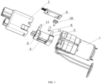
- a pump-valve integrated machine for a pneumatic lumbar support of an automobile seat including: an air pump, a pump valve connection base, an electromagnetic air valve lower base, a normally open electromagnetic air valve, an electromagnetic air valve upper cover, and a control circuit board, where a one-way air outlet structure is processed on the pump valve connection base, and the one-way air outlet structure on the pump valve connection base is opposite to and in communication with an air outlet hole of the air pump;
- the electromagnetic air valve lower base is fixed onto the air pump, and a mounting groove is processed on a bottom of the electromagnetic air valve lower base, and the pump valve connection base is provided within the mounting groove, a ventilation hole is processed on the electromagnetic air valve lower base opposite to the one-way air outlet structure of the pump valve connection base;
- the normally open electromagnetic air valve is disposed on the electromagnetic air valve lower base, an air inlet end of the normally open electromagnetic air valve corresponds to the ventilation hole of the electromagnetic air valve lower base;
- the pump valve connection base includes a rubber sheet bracket and a one-way rubber sheet.
- a connection protrusion is processed on a bottom of the rubber sheet bracket, and the connection protrusion is disposed on the air outlet hole of the air pump.
- a mounting groove is processed around the connection protrusion, and the mounting groove is provided with a sealing ring therein.
- the mounting hole for the one-way rubber sheet is processed above the rubber sheet bracket, and an air vent hole is processed around the mounting hole for the one-way rubber sheet.
- the one-way rubber sheet is disposed in the mounting hole for the one-way rubber sheet and covers the air vent hole.
- a mounting groove is processed around the one-way rubber sheet, and a sealing ring is disposed in the mounting groove.
- the pump-valve integrated machine further includes a housing disposed on the air pump, and the electromagnetic air valve lower base, the normally open electromagnetic air valve, and the electromagnetic air valve upper cover are all disposed in the housing.
- the pump-valve integrated machine further includes a pressure sensor, and a mounting hole for the pressure sensor is processed on a side wall of the electromagnetic air valve lower base.
- the mounting hole for the pressure sensor communicates with the ventilation hole, and a connection pipe is disposed outside the mounting hole for the pressure sensor, and the connection pipe is connected with the pressure sensor, to transmit a pressure signal to the pressure sensor.
- the pressure sensor and the control circuit board are electrically connected.
- a mounting groove is processed on the electromagnetic air valve lower base and around the ventilation hole, and a sealing ring is disposed in the mounting groove, and is configured to achieve sealing between the electromagnetic air valve lower base and the normally open electromagnetic air valve.
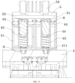
- the normally open electromagnetic air valve includes an outer frame, a wire rack, a valve core, a rubber plug, and a spring, where axial air inlet groove is processed on the bottom of the outer frame, the axial air inlet groove corresponds to the ventilation hole of the electromagnetic air valve lower base;
- the wire rack is disposed on the outer frame, and a varnished wire is wound outside the wire rack;
- the valve core is sleeved in the wire rack, and upper and lower ends of the valve core are each provided with a groove, and the two grooves are each provided with the rubber plug;
- the spring is sleeved on an outer side surface of a butting section of the valve core and the outer frame, and the valve core and the wire rack are in clearance fit to form a ventilation passage; an air inlet end of the ventilation passage is communicated with the axial air inlet groove, and when the valve core is under the action of the spring, the rubber plug is directly above the axial air inlet groove, and when the electromagnetic air valve is powered on
- an air outlet passage is disposed in the electromagnetic air valve upper cover, and an air outlet hole of the air outlet passage is disposed on a side wall of the electromagnetic air valve upper cover, and an air vent hole is processed on the air outlet passage at a position corresponding to the rubber plug on an upper end of the valve core, an air inlet passage is disposed on a side wall of the air vent hole, and the air inlet passage is communicated with the air vent hole, the air outlet connector and the normally open electromagnetic air valve; and in a normal case, a seal forms between the rubber plug on the upper end of the valve core and the air vent hole on the air outlet passage, and an air bag is inflated by the gas from the normally open electromagnetic air valve through the air inlet passage and the air outlet connector; when the electromagnetic air valve is powered on, the air pump stops inflating, and air in the air bag is discharged through the air outlet connector, the air inlet passage, the air vent hole, and the air outlet passage.
- a placement groove is processed in the electromagnetic air valve upper cover at a position corresponding to the wire rack, and one end of the wire rack is inserted into the placement groove; and a mounting groove is processed around the placement groove, and is provided with a sealing ring in the mounting groove.
- a noise-reduction cotton is pasted on the outer side of the air outlet of the air outlet passage.
- the pump-valve integrated machine for a pneumatic lumbar support of an automobile seat includes: an air pump 1, a pump valve connection base 2, an electromagnetic air valve lower base 3, a normally open electromagnetic air valve 4, an electromagnetic air valve upper cover 5, a control circuit board 6, and a housing 7, where the air pump 1 is of the model of JQF1418136, with the manufacturer: Shenzhen Jichuangxing Technology Co., Ltd.
- the air pump 1 may be chosen to have one air outlet hole, two air outlet holes, three or more air outlet holes according to actual needs. The air pump with two air outlet holes is selected in this embodiment.
- a one-way air outlet structure is processed on the pump valve connection base 2, and the one-way air outlet structure of the pump valve connection base 2 is opposite to and in communication with the air outlet hole of the air pump 1.
- the electromagnetic air valve lower base 3 is fixed onto the air pump 1 by a bolt.
- the normally open electromagnetic air valve 4 is disposed on the electromagnetic air valve lower base 3.
- the electromagnetic air valve upper cover 5 is disposed above the normally open electromagnetic air valve 4.
- the air outlet connector of the electromagnetic air valve upper cover 5 corresponds to the valve core of the normally open electromagnetic air valve 4.
- the normally open electromagnetic air valve 4 is open when power is off.
- the gas of the air pump 1 is discharged from the air outlet connector of the electromagnetic air valve upper cover 5 through the normally open electromagnetic air valve 4.
- the control circuit board 6 is used to control the operation of the normally open electromagnetic air valve 4 and the air pump 1.
- the pump valve connection base 2 includes a rubber sheet bracket 21 and a one-way rubber sheet 22.
- a connection protrusion 24 is processed on the bottom of the rubber sheet bracket 21, and the connection protrusion 24 is disposed on the air outlet hole of the air pump 1.
- a mounting groove is processed around the connection protrusion 24, and the mounting groove is provided with a sealing ring 8 therein.
- the mounting hole for the one-way rubber sheet is processed above the rubber sheet bracket 21, and an air vent hole 23 is processed around the mounting hole for the one-way rubber sheet.
- the one-way rubber sheet 22 is disposed in the mounting hole for the one-way rubber sheet and covers the air vent hole 23.
- a mounting groove is processed around the one-way rubber sheet 22, and the sealing ring 8 is disposed in the mounting groove.
- a mounting groove 31 is processed on bottom of the electromagnetic air valve lower base 3, and the mounting groove 31 is provided with the pump valve connection base 2.
- a ventilation hole 32 is processed on the electromagnetic air valve lower base 3 at a position opposite to the one-way air outlet structure of the pump valve connection base 2, a mounting groove is processed on the electromagnetic air valve lower base 3 and around the ventilation hole 32, and a sealing ring is disposed in the mounting groove, and is used to achieve sealing between the electromagnetic air valve lower base 3 and the normally open electromagnetic air valve 4.
- the normally open electromagnetic air valve 4 includes an outer frame 41, a wire rack 42, a valve core 43, a rubber plug 44, and a spring 45, where an axial air inlet groove 411 is processed on the bottom of the outer frame, the axial air inlet groove corresponds to the ventilation hole 32 of the electromagnetic air valve lower base 3;
- the wire rack 42 is disposed on the outer frame 41, and a varnished wire is wound outside the wire rack 42;
- the valve core 43 is sleeved in the wire rack 42, and grooves 431 are provided at the upper and lower ends of the valve core 43, and the rubber plugs 44 are disposed in the two grooves 341;
- the spring 45 is sleeved at the outer side of the butting section of the valve core 43 and the outer frame 41, and the valve core 43 and the wire rack 42 are in clearance fit to form a ventilation passage;
- the air inlet end of the ventilation passage is communicated with the axial air inlet groove 411, and when the valve core 43 is under the
- an air outlet passage 51 is disposed in the electromagnetic air valve upper cover 5, and the air outlet hole of the air outlet passage 51 is disposed on the side wall of the electromagnetic air valve upper cover.
- a noise-reduction cotton is pasted on the outer side of the air outlet hole of the air outlet passage, and is used to reduce the noise.
- An air vent hole 52 is processed on the air outlet passage 51 at a position corresponding to the rubber plug 44 on the upper end of the valve core 43, and an air inlet passage 53 is disposed on the side wall of the air vent hole 52, and the air inlet passage 53 is communicated with the air vent hole 52, the air outlet connector 54 and the normally open electromagnetic air valve 4.
- a seal forms between the rubber plug 44 on the upper end of the valve core 43 and the air vent hole 52 on the air outlet passage 51, and the air bag is inflated by the gas from the normally open electromagnetic air valve 4 through the air inlet passage 53 and the air outlet connector 54.
- the air pump 1 stops inflating, and the air in the air bag 1 is discharged through the air outlet connector 54, the air inlet passage 53, the air vent hole 52, and the air outlet passage 51.
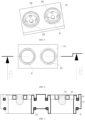
- the air outlet hole on the air pump 1 of the present application are respectively connected to the normally open electromagnetic air valves 4, and each normally open electromagnetic air valve 4 can individually control the inflation of different air outlet holes, which can achieve inflating of multiple air bags simultaneously, or selectively inflate several air bags of the multiple air bags, which is more full functional and more convenient to use.
- a mounting hole 33 for a pressure sensor is processed on the side wall of the electromagnetic air valve lower base 3.
- the mounting hole 33 for the pressure sensor communicates with the ventilation hole 32, and the a connection pipe 9 is disposed outside the mounting hole 33 for the pressure sensor, and the connection pipe 9 is connected with the pressure sensor 10, and is used to transmit a pressure signal to the pressure sensor 10.
- the pressure sensor 10 and a main control chip on the control circuit board 6 are electrically connected.
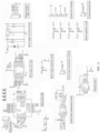
- the main control chip 6 is electrically connected with a drive pump valve chip, and the drive pump valve chip is electrically connected with a control pump interface and a control valve interface, and connected with the air pump 1 and the normally open electromagnetic air valve 4 by the control pump interface and the control valve interface ( FIG. 14 ).
- the main control chip detects that the pressure signal exceeds a preset value, the main control chip controls the drive pump valve chip so as to electrify the normally open electromagnetic air valve 4 and stop inflating the air bag to effectively protect the air bag and prevent the air bag from being inflating to explode.
- the height of the air bag can also be adjusted.
- control circuit board 6 is disposed on the air pump and on one side of the normally open electromagnetic air valve 4 (see FIG. 1 , FIG. 13 ), the air pump 1 is electrically connected with the normally open electromagnetic air valve 4 and the control circuit board 6, and the pressure sensor 10 is disposed on the control circuit board 6 and is disposed between the control circuit board 6 and the electromagnetic air valve lower base 3.
- the electromagnetic air valve upper cover 5 and the electromagnetic air valve lower base 3 are each provided with a support column 11 at a side in contact with the control circuit board 6, to install and support the control circuit board 6.
- the pump-valve integrated machine is controlled by the control system in the vehicle body, so as to achieve the adjustment of the height of the pneumatic lumbar support.
- the control circuit board 6 is also provided with a button and power supply interface, and a vehicle body communication circuit electrically connected to the main control chip.
- the button and the power supply interface are connected with a button acquisition circuit and a power supply conversion circuit, and the button acquisition circuit is electrically connected with the main control chip, and the preset pressure valve of the main control chip is adjusted through a button on the vehicle body, achieving the functions such as parameter setting.
- the power supply conversion circuit is electrically connected with the main control chip through the chip interface (see FIG. 14 ).
Landscapes
- Engineering & Computer Science (AREA)
- Mechanical Engineering (AREA)
- General Engineering & Computer Science (AREA)
- Aviation & Aerospace Engineering (AREA)
- Transportation (AREA)
- Seats For Vehicles (AREA)
- Compressor (AREA)
- Compressors, Vaccum Pumps And Other Relevant Systems (AREA)
- Check Valves (AREA)
- Magnetically Actuated Valves (AREA)
Claims (8)
- Integrierte Pumpe-Ventil-Maschine für eine pneumatische Lendenwirbelstütze eines Automobilsitzes, umfassend: eine Luftpumpe (1), eine Pumpenventil-Verbindungsbasis (2), eine elektromagnetische Luftventil-Unterbasis (3), ein üblicherweise offenes elektromagnetisches Luftventil (4), eine obere Abdeckung (5) des elektromagnetischen Luftventils und eine Steuerplatine (6), wobei eine Einweg-Luftauslassstruktur an der Pumpenventil-Verbindungsbasis (2) verarbeitet ist und die Einweg-Luftauslassstruktur an der Pumpenventil-Verbindungsbasis (2) einem Luftauslassloch der Luftpumpe (1) gegenüberliegt und mit diesem in Verbindung steht, wobei die untere Basis (3) des elektromagnetischen Luftventils an der Luftpumpe (1) befestigt ist und eine Montagenut (31) an einer Unterseite der unteren Basis (3) des elektromagnetischen Luftventils ausgebildet ist und mit der Pumpenventilverbindungsbasis (2) versehen ist, wobei eine Belüftungsöffnung (32) an der unteren Basis (3) des elektromagnetischen Luftventils gegenüber der Einwegluftauslassstruktur der Pumpenventilverbindungsbasis (2) ausgebildet ist, wobei das üblicherweise offene elektromagnetische Luftventil (4) auf der unteren Basis (3) des elektromagnetischen Luftventils angeordnet ist, wobei ein Lufteinlassende des üblicherweise offenen elektromagnetischen Luftventils (4) dem Belüftungsloch (32) der unteren Basis (3) des elektromagnetischen Luftventils entspricht, wobei die obere Abdeckung (5) des elektromagnetischen Luftventils oberhalb des üblicherweise offenen elektromagnetischen Luftventils (4) bereitgestellt ist, und wobei ein Luftauslassanschluss (54) der oberen Abdeckung (5) des elektromagnetischen Luftventils einem Ventileinsatz (43) des üblicherweise offenen elektromagnetischen Luftventils (4) entspricht, wobei das üblicherweise offene elektromagnetische Luftventil (4) ist offen, wenn es nicht eingeschaltet ist, und Gas der Luftpumpe (1) aus dem Luftauslassanschluss (54) durch das üblicherweise offene elektromagnetische Luftventil (4) ausgestoßen wird, und wenn das üblicherweise offene elektromagnetische Luftventil (4) eingeschaltet ist, das Gas der Luftpumpe (1) nicht aus dem Luftauslassanschluss (54) durch das üblicherweise offene elektromagnetische Luftventil (4) ausgestoßen werden kann, und wobei die Steuerplatine (6) so konfiguriert ist, dass sie den Betrieb des üblicherweise offenen elektromagnetischen Luftventils (4) und der Luftpumpe (1) steuert,
dadurch gekennzeichnet, dass die Pumpenventilanschlussbasis (2) eine Gummiplattenhalterung (21) und eine Einweg-Gummiplatte (22) aufweist, wobei ein Verbindungsvorsprung (24) an einem Boden der Gummiplattenhalterung (21) verarbeitet ist und der Verbindungsvorsprung (24) an dem Luftauslassloch der Luftpumpe (1) angeordnet ist, wobei eine Montagenut um den Verbindungsvorsprung (24) herum verarbeitet ist und mit einem Dichtungsring (8) in der Montagenut versehen ist; ein Montageloch für die Einweg-Gummiplatte oberhalb der Gummiplattenhalterung (21) verarbeitet ist, und ein Entlüftungsloch (23) um das Montageloch für die Einweg-Gummiplatte herum verarbeitet ist, wobei die Einweg-Gummiplatte (22) in dem Montageloch für die Einweg-Gummiplatte angeordnet ist und das Entlüftungsloch (23) abdeckt, und wobei eine weitere Montagenut um die Einweg-Gummiplatte (22) herum verarbeitet und mit einem weiteren Dichtungsring (8) in der Montagenut versehen ist. - Integrierte Pumpe-Ventil-Maschine für die pneumatische Lendenwirbelstütze des Autositzes nach Anspruch 1, wobei die integrierte Pumpe-Ventil-Maschine ferner ein Gehäuse aufweist, wobei das Gehäuse auf der Luftpumpe (1) angeordnet ist und die untere Basis (3) des elektromagnetischen Luftventils, das üblicherweise offene elektromagnetische Luftventil (4) und die obere Abdeckung (5) des elektromagnetischen Luftventils innerhalb des Gehäuses bereitgestellt sind.
- Integrierte Pumpe-Ventil-Maschine für die pneumatische Lendenwirbelstütze des Autositzes nach Anspruch 1, wobei die integrierte Pumpe-Ventil-Maschine ferner einen Drucksensor (10) aufweist und ein Montageloch für den Drucksensor (33) an einer Seitenwand der unteren Basis (3) des elektromagnetischen Luftventils ausgebildet ist, wobei das Montageloch für den Drucksensor (33) mit dem Belüftungsloch (32) in Verbindung steht, und ein Verbindungsrohr (9) außerhalb des Montagelochs für den Drucksensor (33) angeordnet ist, und das Verbindungsrohr (9) mit dem Drucksensor (10) verbunden ist und so konfiguriert ist, dass es ein Drucksignal an den Drucksensor (10) überträgt, wobei der Drucksensor (10) und die Steuerplatine (6) elektrisch verbunden sind.
- Integrierte Pumpe-Ventil-Maschine für die pneumatische Lendenwirbelstütze des Autositzes nach einem der Ansprüche 1 bis 3, wobei eine Montagenut an der unteren Basis (2) des elektromagnetischen Luftventils und um das Entlüftungsloch (32) herum verarbeitet ist, und ein Dichtungsring (8) in der Montagenut angeordnet ist und so konfiguriert ist, dass er eine Abdichtung zwischen der unteren Basis (3) des elektromagnetischen Luftventils und dem üblicherweise offenen elektromagnetischen Luftventil (4) erreicht.
- Integrierte Pumpe-Ventil-Maschine für die pneumatische Lendenwirbelstütze von Automobilsitz nach einem der Ansprüche 1 bis 3, wobei das üblicherweise offene elektromagnetische Luftventil (4) einen Außenrahmen (41), ein Drahtgestell (42), einen Ventileinsatz (43), einen Gummistopfen (44) und eine Feder (45) aufweist, wobei eine axiale Lufteinlassnut (411) an einem Boden des Außenrahmens (41) verarbeitet ist, wobei die axiale Lufteinlassnut (411) dem Belüftungsloch (32) der unteren Basis (3) des elektromagnetischen Luftventils entspricht, wobei das Drahtgestell (42) auf dem äußeren Rahmen (41) angeordnet ist und ein lackierter Draht außerhalb des Drahtgestells (42) gewickelt ist, wobei der Ventileinsatz (43) in das Drahtgestell (42) eingeschoben ist und obere und untere Enden des Ventileinsatzes (43) jeweils mit einer Nut (431) versehen sind und die beiden Nuten jeweils mit dem Gummistopfen (44) versehen sind, wobei die Feder (45) an einer äußeren Seitenfläche eines Stoßabschnitts des Ventileinsatzes (43) und des Außenrahmens (41) ummantelt ist und der Ventileinsatz (43) und das Drahtgestell (42) in Spielpassung sind, um einen Belüftungsdurchgang zu bilden, wobei ein Lufteinlassende des Belüftungsdurchgangs mit der axialen Lufteinlassnut (411) in Verbindung steht, und wenn der Ventileinsatz (43) unter der Wirkung der Feder (45) steht, der Gummistopfen (44) direkt über der axialen Lufteinlassnut (411) angeordnet ist, und wenn das elektromagnetische Luftventil eingeschaltet ist, der Gummistopfen (44) eingerichtet ist, unter der Wirkung einer elektromagnetischen Kraft eine Abdichtung mit der axialen Lufteinlassnut (411) zu bilden.
- Integrierte Pumpe-Ventil-Maschine für die pneumatische Lendenwirbelstütze des Autositzes nach einem der Ansprüche 1 bis 3, wobei ein Luftauslasskanal (51) in der oberen Abdeckung (5) des elektromagnetischen Luftventils angeordnet ist, und ein Luftauslassloch des Luftauslasskanals an einer Seitenwand der oberen Abdeckung (5) des elektromagnetischen Luftventils angeordnet ist, und ein Luftauslassloch (52) an dem Luftauslassdurchgang (51) an einer Position verarbeitet ist, die dem Gummistopfen (44) an einem oberen Ende des Ventileinsatzes (43) entspricht, wobei ein Lufteinlassdurchgang (53) an einer Seitenwand des Luftauslasslochs angeordnet ist und der Lufteinlassdurchgang (53) mit dem Luftauslassloch (52), dem Luftauslassverbinder (54) und dem üblicherweise offenen elektromagnetischen Luftventil (4) verbunden ist, wobei in einem normalen Fall bildet sich eine Dichtung zwischen dem Gummistopfen (44) am oberen Ende des Ventileinsatzes (43) und dem Luftentlüftungsloch (52) am Luftauslassdurchgang (51), und ein Luftsack wird durch das Gas aus dem üblicherweise offenen elektromagnetischen Luftventil (4) durch den Lufteinlassdurchgang (53) und den Luftauslassanschluss (54) aufgeblasen, wobei, wenn das elektromagnetische Luftventil eingeschaltet wird, die Luftpumpe (1) aufhört, sich aufzublasen und die Luft in dem Luftsack durch den Luftauslassanschluss (54), den Lufteinlasskanal (53), das Luftentlüftungsloch (52) und den Luftauslasskanal (51) ausgestoßen wird.
- Integrierte Pumpe-Ventil-Maschine für die pneumatische Lendenwirbelstütze des Autositzes nach Anspruch 6, wobei eine Platzierungsnut in der oberen Abdeckung (5) des elektromagnetischen Luftventils an einer Position gegenüber dem Drahtgestell (42) ausgebildet ist und ein Ende des Drahtgestells (42) in die Platzierungsnut eingesetzt ist, wobei eine Montagenut um die Platzierungsnut herum ausgebildet und mit einem Dichtungsring in der Montagenut versehen ist.
- Integrierte Pumpe-Ventil-Maschine für die pneumatische Lendenwirbelstütze des Autositzes nach Anspruch 6, wobei eine geräuschdämmende Watte auf die Außenseite des Luftauslasses des Luftauslasskanals (51) geklebt ist.
Applications Claiming Priority (2)
| Application Number | Priority Date | Filing Date | Title |
|---|---|---|---|
| CN201910256177.0A CN110030175B (zh) | 2019-04-01 | 2019-04-01 | 汽车座椅气动腰托用泵阀一体机 |
| PCT/CN2020/082509 WO2020200208A1 (zh) | 2019-04-01 | 2020-03-31 | 汽车座椅气动腰托用泵阀一体机 |
Publications (4)
| Publication Number | Publication Date |
|---|---|
| EP3936720A1 EP3936720A1 (de) | 2022-01-12 |
| EP3936720A4 EP3936720A4 (de) | 2022-03-23 |
| EP3936720B1 true EP3936720B1 (de) | 2023-06-07 |
| EP3936720C0 EP3936720C0 (de) | 2023-06-07 |
Family
ID=67237140
Family Applications (1)
| Application Number | Title | Priority Date | Filing Date |
|---|---|---|---|
| EP20784995.1A Active EP3936720B1 (de) | 2019-04-01 | 2020-03-31 | Pumpenventil-all-in-one-maschine für eine pneumatische lumbalstütze eines fahrzeugsitzes |
Country Status (5)
| Country | Link |
|---|---|
| US (1) | US12078161B2 (de) |
| EP (1) | EP3936720B1 (de) |
| JP (1) | JP7286797B2 (de) |
| CN (1) | CN110030175B (de) |
| WO (1) | WO2020200208A1 (de) |
Families Citing this family (11)
| Publication number | Priority date | Publication date | Assignee | Title |
|---|---|---|---|---|
| CN110030175B (zh) * | 2019-04-01 | 2024-04-12 | 新发展(长春)汽车自控系统有限公司 | 汽车座椅气动腰托用泵阀一体机 |
| DE112020000106T5 (de) | 2019-11-13 | 2021-07-15 | Langfang Golden Time Technology Development Co., Ltd. | Pumpenventilmodul und dessen Betriebsverfahren, Magnetventil-basiertesPumpenventilmodul zur Bereitstellung einer Massagefunktion für einen Fahrzeugsitz,sowie Fahrzeugsitz |
| CN110822133A (zh) * | 2019-11-13 | 2020-02-21 | 东莞市安海思精密电子有限公司 | 一种复合式电磁阀、泵阀模组及汽车座椅 |
| CN111791778B (zh) * | 2020-06-04 | 2022-03-08 | 廊坊市金色时光科技发展有限公司 | 一种翘板式调节开关 |
| CN113915106B (zh) * | 2020-12-24 | 2025-02-18 | 安闻科技集团股份有限公司 | 一种一体式泵阀总成及汽车座椅用气动调节系统 |
| CN112959929B (zh) * | 2021-02-04 | 2022-06-03 | 廊坊市金色时光科技发展有限公司 | 一种电磁阀泵阀模组及汽车座椅用气动调节系统 |
| CN113719648A (zh) * | 2021-09-13 | 2021-11-30 | 厦门微能电子科技有限公司 | 电磁阀裸露外且独立控制具有泄压功能的一体式泵阀 |
| CN113799665B (zh) * | 2021-10-29 | 2022-11-22 | 北京经纬恒润科技股份有限公司 | 一种座椅支撑控制方法及装置 |
| CN114837918B (zh) * | 2022-04-18 | 2025-02-18 | 江苏恩迪汽车系统股份有限公司 | 快速装配式气动腰托用泵阀一体机及装配方法 |
| CN116080502B (zh) * | 2023-02-20 | 2023-07-14 | 长春亚大汽车零件制造有限公司 | 一种集成汽车座椅腰托气囊开关和侧翼气囊开关的座椅阀 |
| WO2026015984A1 (en) * | 2024-07-18 | 2026-01-22 | Leggett & Platt Canada Co. | Pump and valve system |
Family Cites Families (24)
| Publication number | Priority date | Publication date | Assignee | Title |
|---|---|---|---|---|
| JP2002364533A (ja) | 2001-06-07 | 2002-12-18 | Saginomiya Seisakusho Inc | 電磁制御弁 |
| FR2858432B1 (fr) * | 2003-08-01 | 2005-10-07 | Eaton Corp | Electrovanne de regulation de debit et de pression |
| EP2361800B1 (de) * | 2010-02-17 | 2013-04-24 | L & P Swiss Holding AG | Einstellvorrichtung für einen Sitz und Verfahren zur Bedienung der Einstellvorrichtung |
| EP2769878B1 (de) * | 2013-02-20 | 2015-03-25 | Schukra Gerätebau GmbH | Sitzeinstellvorrichtung und Verfahren zur Sitzeinstellung |
| US10086720B2 (en) * | 2013-12-13 | 2018-10-02 | Kongsberg Automotive Ab | SMA valve for controlling air supply to an air cell in a vehicle seat |
| CN203717289U (zh) * | 2014-01-27 | 2014-07-16 | 惠州市唐群电子有限公司 | 能快速安装于气泵上的控制阀 |
| CN105443832A (zh) * | 2014-07-24 | 2016-03-30 | 惠州市唐群电子有限公司 | 电磁气阀 |
| CN105443807B (zh) * | 2014-07-24 | 2017-11-14 | 惠州市唐群座椅科技股份有限公司 | 复合式配气阀组 |
| CH711796A1 (de) * | 2015-11-18 | 2017-05-31 | Lantal Textiles Ag | Pneumatisches Kissen mit Pumpeneinheit. |
| CN107512207A (zh) | 2017-08-23 | 2017-12-26 | 厦门乾泽电子科技有限公司 | 一种座椅调节装置及座椅调节方法 |
| CN207670135U (zh) * | 2017-12-07 | 2018-07-31 | 青岛孔辉智能悬架系统有限公司 | 一种车辆电控空气悬架用高度集成的五联阀 |
| CN207814535U (zh) * | 2018-02-06 | 2018-09-04 | 厦门乾泽电子科技有限公司 | 电磁气阀阀组 |
| CN208010562U (zh) * | 2018-02-06 | 2018-10-26 | 厦门乾泽电子科技有限公司 | 带常闭电磁气阀的泵阀一体式微型气泵 |
| CN208010548U (zh) * | 2018-02-06 | 2018-10-26 | 厦门乾泽电子科技有限公司 | 带常开电磁气阀的泵阀一体式微型气泵 |
| CN207809133U (zh) * | 2018-02-06 | 2018-09-04 | 厦门乾泽电子科技有限公司 | 装有泵阀一体式微型气泵的气动腰托 |
| CN108361419B (zh) * | 2018-04-10 | 2022-01-11 | 厦门乾泽电子科技有限公司 | 一种集成式气阀结构 |
| CN208534727U (zh) * | 2018-08-03 | 2019-02-22 | 厦门乾泽电子科技有限公司 | 低噪音限压结构以及具有该结构的气泵和电磁阀组 |
| CN110949214A (zh) * | 2018-09-27 | 2020-04-03 | 科际精密股份有限公司 | 用以调整气囊的泵阀组合装置 |
| CN111075698B (zh) * | 2018-10-19 | 2021-10-15 | 科际精密股份有限公司 | 用以调整气囊的泵阀组合装置 |
| CN209164045U (zh) * | 2018-11-19 | 2019-07-26 | 浙江锐韦机电科技有限公司 | 泵阀一体机构 |
| CN109318770B (zh) * | 2018-11-27 | 2023-12-12 | 宁波拓普集团股份有限公司 | 一种集成腰部支撑和多点按摩的座椅多气囊舒适系统 |
| CN210068424U (zh) * | 2019-04-01 | 2020-02-14 | 新发展(长春)汽车自控系统有限公司 | 汽车座椅气动腰托用泵阀一体机 |
| CN110030175B (zh) | 2019-04-01 | 2024-04-12 | 新发展(长春)汽车自控系统有限公司 | 汽车座椅气动腰托用泵阀一体机 |
| DE112020000106T5 (de) * | 2019-11-13 | 2021-07-15 | Langfang Golden Time Technology Development Co., Ltd. | Pumpenventilmodul und dessen Betriebsverfahren, Magnetventil-basiertesPumpenventilmodul zur Bereitstellung einer Massagefunktion für einen Fahrzeugsitz,sowie Fahrzeugsitz |
-
2019
- 2019-04-01 CN CN201910256177.0A patent/CN110030175B/zh active Active
-
2020
- 2020-03-31 JP JP2021560507A patent/JP7286797B2/ja active Active
- 2020-03-31 WO PCT/CN2020/082509 patent/WO2020200208A1/zh not_active Ceased
- 2020-03-31 US US17/600,496 patent/US12078161B2/en active Active
- 2020-03-31 EP EP20784995.1A patent/EP3936720B1/de active Active
Also Published As
| Publication number | Publication date |
|---|---|
| US20220170451A1 (en) | 2022-06-02 |
| CN110030175A (zh) | 2019-07-19 |
| JP2022528963A (ja) | 2022-06-16 |
| CN110030175B (zh) | 2024-04-12 |
| EP3936720A1 (de) | 2022-01-12 |
| EP3936720C0 (de) | 2023-06-07 |
| JP7286797B2 (ja) | 2023-06-05 |
| WO2020200208A1 (zh) | 2020-10-08 |
| EP3936720A4 (de) | 2022-03-23 |
| US12078161B2 (en) | 2024-09-03 |
Similar Documents
| Publication | Publication Date | Title |
|---|---|---|
| EP3936720B1 (de) | Pumpenventil-all-in-one-maschine für eine pneumatische lumbalstütze eines fahrzeugsitzes | |
| US5529377A (en) | Air cell module for automotive seat | |
| CN105172492B (zh) | 一种自行车智能感压充气装置 | |
| WO1996010903A3 (en) | Valve connector | |
| CN211009180U (zh) | 一种高低压一体充气泵和充气产品 | |
| CN210068424U (zh) | 汽车座椅气动腰托用泵阀一体机 | |
| CN210290878U (zh) | 可自由组合的四位三通电磁阀 | |
| CN110513312B (zh) | 充放气气泵 | |
| CN216554292U (zh) | 一种气路转换板及汽车座椅腰托用气泵阀一体结构 | |
| CN205207134U (zh) | 气泵控制系统 | |
| CN210769398U (zh) | 一种可内、外置的气泵组件和充气产品 | |
| CN216045608U (zh) | 一种具有独立泄压阀的电磁阀组件及气动腰托按摩系统 | |
| CN218661186U (zh) | 一种可充气的外置式胎压监测传感装置 | |
| CN102828936B (zh) | 一种多功能的打气筒气嘴组件 | |
| CN217270739U (zh) | 用于调节座椅气动腰托的一体式泵阀 | |
| CN113982886A (zh) | 一种汽车座椅腰托用气泵阀一体结构及使用方法 | |
| CN217319957U (zh) | 一种空气悬架的集成式供气单元 | |
| CN2614959Y (zh) | 可调控气压的轮胎充气连接器 | |
| CN210026924U (zh) | 一种可自动补气的充气轮胎 | |
| CN219838391U (zh) | 一种集成阀总成、车轮充放气系统及车辆 | |
| CN223574129U (zh) | 一种基于汽车轮胎的胎压传感器 | |
| CN223794299U (zh) | 一种充放气一体式气泵 | |
| CN223152333U (zh) | 旋盖式充放气泵 | |
| CN223062686U (zh) | 电驱阀门充放气泵 | |
| CN223062685U (zh) | 可变通道充放气泵 |
Legal Events
| Date | Code | Title | Description |
|---|---|---|---|
| STAA | Information on the status of an ep patent application or granted ep patent |
Free format text: STATUS: THE INTERNATIONAL PUBLICATION HAS BEEN MADE |
|
| PUAI | Public reference made under article 153(3) epc to a published international application that has entered the european phase |
Free format text: ORIGINAL CODE: 0009012 |
|
| STAA | Information on the status of an ep patent application or granted ep patent |
Free format text: STATUS: REQUEST FOR EXAMINATION WAS MADE |
|
| 17P | Request for examination filed |
Effective date: 20211007 |
|
| AK | Designated contracting states |
Kind code of ref document: A1 Designated state(s): AL AT BE BG CH CY CZ DE DK EE ES FI FR GB GR HR HU IE IS IT LI LT LU LV MC MK MT NL NO PL PT RO RS SE SI SK SM TR |
|
| A4 | Supplementary search report drawn up and despatched |
Effective date: 20220221 |
|
| RIC1 | Information provided on ipc code assigned before grant |
Ipc: F04B 45/04 20060101ALI20220215BHEP Ipc: F04B 43/02 20060101ALI20220215BHEP Ipc: B60N 2/66 20060101ALI20220215BHEP Ipc: F04B 49/22 20060101ALI20220215BHEP Ipc: F04B 39/00 20060101ALI20220215BHEP Ipc: F04B 39/10 20060101AFI20220215BHEP |
|
| DAV | Request for validation of the european patent (deleted) | ||
| DAX | Request for extension of the european patent (deleted) | ||
| GRAP | Despatch of communication of intention to grant a patent |
Free format text: ORIGINAL CODE: EPIDOSNIGR1 |
|
| STAA | Information on the status of an ep patent application or granted ep patent |
Free format text: STATUS: GRANT OF PATENT IS INTENDED |
|
| INTG | Intention to grant announced |
Effective date: 20221206 |
|
| GRAS | Grant fee paid |
Free format text: ORIGINAL CODE: EPIDOSNIGR3 |
|
| GRAA | (expected) grant |
Free format text: ORIGINAL CODE: 0009210 |
|
| STAA | Information on the status of an ep patent application or granted ep patent |
Free format text: STATUS: THE PATENT HAS BEEN GRANTED |
|
| AK | Designated contracting states |
Kind code of ref document: B1 Designated state(s): AL AT BE BG CH CY CZ DE DK EE ES FI FR GB GR HR HU IE IS IT LI LT LU LV MC MK MT NL NO PL PT RO RS SE SI SK SM TR |
|
| REG | Reference to a national code |
Ref country code: GB Ref legal event code: FG4D |
|
| REG | Reference to a national code |
Ref country code: CH Ref legal event code: EP Ref country code: AT Ref legal event code: REF Ref document number: 1575834 Country of ref document: AT Kind code of ref document: T Effective date: 20230615 Ref country code: DE Ref legal event code: R096 Ref document number: 602020012278 Country of ref document: DE |
|
| U01 | Request for unitary effect filed |
Effective date: 20230703 |
|
| U07 | Unitary effect registered |
Designated state(s): AT BE BG DE DK EE FI FR IT LT LU LV MT NL PT SE SI Effective date: 20230713 |
|
| REG | Reference to a national code |
Ref country code: LT Ref legal event code: MG9D |
|
| PG25 | Lapsed in a contracting state [announced via postgrant information from national office to epo] |
Ref country code: NO Free format text: LAPSE BECAUSE OF FAILURE TO SUBMIT A TRANSLATION OF THE DESCRIPTION OR TO PAY THE FEE WITHIN THE PRESCRIBED TIME-LIMIT Effective date: 20230907 Ref country code: ES Free format text: LAPSE BECAUSE OF FAILURE TO SUBMIT A TRANSLATION OF THE DESCRIPTION OR TO PAY THE FEE WITHIN THE PRESCRIBED TIME-LIMIT Effective date: 20230607 |
|
| PG25 | Lapsed in a contracting state [announced via postgrant information from national office to epo] |
Ref country code: RS Free format text: LAPSE BECAUSE OF FAILURE TO SUBMIT A TRANSLATION OF THE DESCRIPTION OR TO PAY THE FEE WITHIN THE PRESCRIBED TIME-LIMIT Effective date: 20230607 Ref country code: HR Free format text: LAPSE BECAUSE OF FAILURE TO SUBMIT A TRANSLATION OF THE DESCRIPTION OR TO PAY THE FEE WITHIN THE PRESCRIBED TIME-LIMIT Effective date: 20230607 Ref country code: GR Free format text: LAPSE BECAUSE OF FAILURE TO SUBMIT A TRANSLATION OF THE DESCRIPTION OR TO PAY THE FEE WITHIN THE PRESCRIBED TIME-LIMIT Effective date: 20230908 |
|
| PG25 | Lapsed in a contracting state [announced via postgrant information from national office to epo] |
Ref country code: SK Free format text: LAPSE BECAUSE OF FAILURE TO SUBMIT A TRANSLATION OF THE DESCRIPTION OR TO PAY THE FEE WITHIN THE PRESCRIBED TIME-LIMIT Effective date: 20230607 |
|
| PG25 | Lapsed in a contracting state [announced via postgrant information from national office to epo] |
Ref country code: IS Free format text: LAPSE BECAUSE OF FAILURE TO SUBMIT A TRANSLATION OF THE DESCRIPTION OR TO PAY THE FEE WITHIN THE PRESCRIBED TIME-LIMIT Effective date: 20231007 |
|
| PG25 | Lapsed in a contracting state [announced via postgrant information from national office to epo] |
Ref country code: SM Free format text: LAPSE BECAUSE OF FAILURE TO SUBMIT A TRANSLATION OF THE DESCRIPTION OR TO PAY THE FEE WITHIN THE PRESCRIBED TIME-LIMIT Effective date: 20230607 Ref country code: SK Free format text: LAPSE BECAUSE OF FAILURE TO SUBMIT A TRANSLATION OF THE DESCRIPTION OR TO PAY THE FEE WITHIN THE PRESCRIBED TIME-LIMIT Effective date: 20230607 Ref country code: RO Free format text: LAPSE BECAUSE OF FAILURE TO SUBMIT A TRANSLATION OF THE DESCRIPTION OR TO PAY THE FEE WITHIN THE PRESCRIBED TIME-LIMIT Effective date: 20230607 Ref country code: IS Free format text: LAPSE BECAUSE OF FAILURE TO SUBMIT A TRANSLATION OF THE DESCRIPTION OR TO PAY THE FEE WITHIN THE PRESCRIBED TIME-LIMIT Effective date: 20231007 Ref country code: CZ Free format text: LAPSE BECAUSE OF FAILURE TO SUBMIT A TRANSLATION OF THE DESCRIPTION OR TO PAY THE FEE WITHIN THE PRESCRIBED TIME-LIMIT Effective date: 20230607 |
|
| PG25 | Lapsed in a contracting state [announced via postgrant information from national office to epo] |
Ref country code: PL Free format text: LAPSE BECAUSE OF FAILURE TO SUBMIT A TRANSLATION OF THE DESCRIPTION OR TO PAY THE FEE WITHIN THE PRESCRIBED TIME-LIMIT Effective date: 20230607 |
|
| REG | Reference to a national code |
Ref country code: DE Ref legal event code: R097 Ref document number: 602020012278 Country of ref document: DE |
|
| PLBE | No opposition filed within time limit |
Free format text: ORIGINAL CODE: 0009261 |
|
| STAA | Information on the status of an ep patent application or granted ep patent |
Free format text: STATUS: NO OPPOSITION FILED WITHIN TIME LIMIT |
|
| U20 | Renewal fee for the european patent with unitary effect paid |
Year of fee payment: 5 Effective date: 20240327 |
|
| 26N | No opposition filed |
Effective date: 20240308 |
|
| REG | Reference to a national code |
Ref country code: CH Ref legal event code: PL |
|
| PG25 | Lapsed in a contracting state [announced via postgrant information from national office to epo] |
Ref country code: MC Free format text: LAPSE BECAUSE OF FAILURE TO SUBMIT A TRANSLATION OF THE DESCRIPTION OR TO PAY THE FEE WITHIN THE PRESCRIBED TIME-LIMIT Effective date: 20230607 |
|
| GBPC | Gb: european patent ceased through non-payment of renewal fee |
Effective date: 20240331 |
|
| PG25 | Lapsed in a contracting state [announced via postgrant information from national office to epo] |
Ref country code: MC Free format text: LAPSE BECAUSE OF FAILURE TO SUBMIT A TRANSLATION OF THE DESCRIPTION OR TO PAY THE FEE WITHIN THE PRESCRIBED TIME-LIMIT Effective date: 20230607 |
|
| PG25 | Lapsed in a contracting state [announced via postgrant information from national office to epo] |
Ref country code: GB Free format text: LAPSE BECAUSE OF NON-PAYMENT OF DUE FEES Effective date: 20240331 |
|
| PG25 | Lapsed in a contracting state [announced via postgrant information from national office to epo] |
Ref country code: IE Free format text: LAPSE BECAUSE OF NON-PAYMENT OF DUE FEES Effective date: 20240331 |
|
| PG25 | Lapsed in a contracting state [announced via postgrant information from national office to epo] |
Ref country code: IE Free format text: LAPSE BECAUSE OF NON-PAYMENT OF DUE FEES Effective date: 20240331 Ref country code: GB Free format text: LAPSE BECAUSE OF NON-PAYMENT OF DUE FEES Effective date: 20240331 Ref country code: CH Free format text: LAPSE BECAUSE OF NON-PAYMENT OF DUE FEES Effective date: 20240331 |
|
| U20 | Renewal fee for the european patent with unitary effect paid |
Year of fee payment: 6 Effective date: 20250331 |
|
| PG25 | Lapsed in a contracting state [announced via postgrant information from national office to epo] |
Ref country code: CY Free format text: LAPSE BECAUSE OF FAILURE TO SUBMIT A TRANSLATION OF THE DESCRIPTION OR TO PAY THE FEE WITHIN THE PRESCRIBED TIME-LIMIT; INVALID AB INITIO Effective date: 20200331 |
|
| PG25 | Lapsed in a contracting state [announced via postgrant information from national office to epo] |
Ref country code: HU Free format text: LAPSE BECAUSE OF FAILURE TO SUBMIT A TRANSLATION OF THE DESCRIPTION OR TO PAY THE FEE WITHIN THE PRESCRIBED TIME-LIMIT; INVALID AB INITIO Effective date: 20200331 |
|
| PG25 | Lapsed in a contracting state [announced via postgrant information from national office to epo] |
Ref country code: TR Free format text: LAPSE BECAUSE OF FAILURE TO SUBMIT A TRANSLATION OF THE DESCRIPTION OR TO PAY THE FEE WITHIN THE PRESCRIBED TIME-LIMIT Effective date: 20230607 |