EP3933264B1 - Pulverbrennstoffverbrennungsvorrichtung und verbrennungsverfahren - Google Patents
Pulverbrennstoffverbrennungsvorrichtung und verbrennungsverfahren Download PDFInfo
- Publication number
- EP3933264B1 EP3933264B1 EP20762202.8A EP20762202A EP3933264B1 EP 3933264 B1 EP3933264 B1 EP 3933264B1 EP 20762202 A EP20762202 A EP 20762202A EP 3933264 B1 EP3933264 B1 EP 3933264B1
- Authority
- EP
- European Patent Office
- Prior art keywords
- air
- fuel
- combustion
- primary
- powder fuel
- Prior art date
- Legal status (The legal status is an assumption and is not a legal conclusion. Google has not performed a legal analysis and makes no representation as to the accuracy of the status listed.)
- Active
Links
Images


Classifications
-
- F—MECHANICAL ENGINEERING; LIGHTING; HEATING; WEAPONS; BLASTING
- F23—COMBUSTION APPARATUS; COMBUSTION PROCESSES
- F23N—REGULATING OR CONTROLLING COMBUSTION
- F23N5/00—Systems for controlling combustion
- F23N5/20—Systems for controlling combustion with a time program acting through electrical means, e.g. using time-delay relays
-
- F—MECHANICAL ENGINEERING; LIGHTING; HEATING; WEAPONS; BLASTING
- F23—COMBUSTION APPARATUS; COMBUSTION PROCESSES
- F23C—METHODS OR APPARATUS FOR COMBUSTION USING FLUID FUEL OR SOLID FUEL SUSPENDED IN A CARRIER GAS OR AIR
- F23C6/00—Combustion apparatus characterised by the combination of two or more combustion chambers or combustion zones, e.g. for staged combustion
- F23C6/04—Combustion apparatus characterised by the combination of two or more combustion chambers or combustion zones, e.g. for staged combustion in series connection
-
- F—MECHANICAL ENGINEERING; LIGHTING; HEATING; WEAPONS; BLASTING
- F23—COMBUSTION APPARATUS; COMBUSTION PROCESSES
- F23C—METHODS OR APPARATUS FOR COMBUSTION USING FLUID FUEL OR SOLID FUEL SUSPENDED IN A CARRIER GAS OR AIR
- F23C7/00—Combustion apparatus characterised by arrangements for air supply
- F23C7/02—Disposition of air supply not passing through burner
-
- F—MECHANICAL ENGINEERING; LIGHTING; HEATING; WEAPONS; BLASTING
- F23—COMBUSTION APPARATUS; COMBUSTION PROCESSES
- F23K—FEEDING FUEL TO COMBUSTION APPARATUS
- F23K3/00—Feeding or distributing of lump or pulverulent fuel to combustion apparatus
- F23K3/02—Pneumatic feeding arrangements, i.e. by air blast
-
- F—MECHANICAL ENGINEERING; LIGHTING; HEATING; WEAPONS; BLASTING
- F23—COMBUSTION APPARATUS; COMBUSTION PROCESSES
- F23L—SUPPLYING AIR OR NON-COMBUSTIBLE LIQUIDS OR GASES TO COMBUSTION APPARATUS IN GENERAL ; VALVES OR DAMPERS SPECIALLY ADAPTED FOR CONTROLLING AIR SUPPLY OR DRAUGHT IN COMBUSTION APPARATUS; INDUCING DRAUGHT IN COMBUSTION APPARATUS; TOPS FOR CHIMNEYS OR VENTILATING SHAFTS; TERMINALS FOR FLUES
- F23L9/00—Passages or apertures for delivering secondary air for completing combustion of fuel
-
- F—MECHANICAL ENGINEERING; LIGHTING; HEATING; WEAPONS; BLASTING
- F23—COMBUSTION APPARATUS; COMBUSTION PROCESSES
- F23C—METHODS OR APPARATUS FOR COMBUSTION USING FLUID FUEL OR SOLID FUEL SUSPENDED IN A CARRIER GAS OR AIR
- F23C2900/00—Special features of, or arrangements for combustion apparatus using fluid fuels or solid fuels suspended in air; Combustion processes therefor
- F23C2900/06041—Staged supply of oxidant
-
- F—MECHANICAL ENGINEERING; LIGHTING; HEATING; WEAPONS; BLASTING
- F23—COMBUSTION APPARATUS; COMBUSTION PROCESSES
- F23C—METHODS OR APPARATUS FOR COMBUSTION USING FLUID FUEL OR SOLID FUEL SUSPENDED IN A CARRIER GAS OR AIR
- F23C6/00—Combustion apparatus characterised by the combination of two or more combustion chambers or combustion zones, e.g. for staged combustion
- F23C6/04—Combustion apparatus characterised by the combination of two or more combustion chambers or combustion zones, e.g. for staged combustion in series connection
- F23C6/042—Combustion apparatus characterised by the combination of two or more combustion chambers or combustion zones, e.g. for staged combustion in series connection with fuel supply in stages
-
- F—MECHANICAL ENGINEERING; LIGHTING; HEATING; WEAPONS; BLASTING
- F23—COMBUSTION APPARATUS; COMBUSTION PROCESSES
- F23C—METHODS OR APPARATUS FOR COMBUSTION USING FLUID FUEL OR SOLID FUEL SUSPENDED IN A CARRIER GAS OR AIR
- F23C9/00—Combustion apparatus characterised by arrangements for returning combustion products or flue gases to the combustion chamber
- F23C9/003—Combustion apparatus characterised by arrangements for returning combustion products or flue gases to the combustion chamber for pulverulent fuel
-
- F—MECHANICAL ENGINEERING; LIGHTING; HEATING; WEAPONS; BLASTING
- F23—COMBUSTION APPARATUS; COMBUSTION PROCESSES
- F23C—METHODS OR APPARATUS FOR COMBUSTION USING FLUID FUEL OR SOLID FUEL SUSPENDED IN A CARRIER GAS OR AIR
- F23C9/00—Combustion apparatus characterised by arrangements for returning combustion products or flue gases to the combustion chamber
- F23C9/06—Combustion apparatus characterised by arrangements for returning combustion products or flue gases to the combustion chamber for completing combustion
-
- F—MECHANICAL ENGINEERING; LIGHTING; HEATING; WEAPONS; BLASTING
- F23—COMBUSTION APPARATUS; COMBUSTION PROCESSES
- F23C—METHODS OR APPARATUS FOR COMBUSTION USING FLUID FUEL OR SOLID FUEL SUSPENDED IN A CARRIER GAS OR AIR
- F23C99/00—Subject-matter not provided for in other groups of this subclass
-
- F—MECHANICAL ENGINEERING; LIGHTING; HEATING; WEAPONS; BLASTING
- F23—COMBUSTION APPARATUS; COMBUSTION PROCESSES
- F23D—BURNERS
- F23D2900/00—Special features of, or arrangements for burners using fluid fuels or solid fuels suspended in a carrier gas
- F23D2900/31019—Mixing tubes combined with burner heads
-
- F—MECHANICAL ENGINEERING; LIGHTING; HEATING; WEAPONS; BLASTING
- F23—COMBUSTION APPARATUS; COMBUSTION PROCESSES
- F23L—SUPPLYING AIR OR NON-COMBUSTIBLE LIQUIDS OR GASES TO COMBUSTION APPARATUS IN GENERAL ; VALVES OR DAMPERS SPECIALLY ADAPTED FOR CONTROLLING AIR SUPPLY OR DRAUGHT IN COMBUSTION APPARATUS; INDUCING DRAUGHT IN COMBUSTION APPARATUS; TOPS FOR CHIMNEYS OR VENTILATING SHAFTS; TERMINALS FOR FLUES
- F23L9/00—Passages or apertures for delivering secondary air for completing combustion of fuel
- F23L9/06—Passages or apertures for delivering secondary air for completing combustion of fuel by discharging the air into the fire bed
Definitions
- the present invention relates to a combustion apparatus for combusting powder fuel, and a combustion method of the combustion apparatus.
- Patent Literature 1 a boiler that uses pulverized coal as fuel to perform combustion and recover combustion heat to supply superheated vapor to power plants and the like is known (refer to Patent Literature 1).
- the boiler according to Patent Literature 1 includes a furnace having a hollow shape and disposed along a vertical direction, and three combustion burners arranged in the vertical direction to inject pulverized coal mixture and the like obtained by mixing solid fuel and combustion air into the furnace.
- the boiler includes a furnace bottom air nozzle that injects combustion air into the furnace below the combustion burner in the vertical direction and a horizontal direction adjustment device capable of adjusting a direction of injection of combustion air through the furnace bottom air nozzle in the horizontal direction.
- the boiler according to Patent Literature 1 adopts such a configuration to promote combustion of fuel inside the furnace and suppress generation of unburned combustibles.
- the boiler according to Patent Literature 1 uses, as disclosed for example in paragraphs 0027 and 0051 of the Publication, pulverized coal formed by mainly pulverizing coal as powder fuel (solid fuel).
- the present inventors utilize a carbonized fuel production apparatus and a carbonized fuel production method disclosed in Patent Literature 2 to produce a high quality carbonized fuel using synthetic resin and the like that has been recovered mainly for reuse as material.
- JP 2017 015268 A discloses a burner comprising a combustion chamber, a fluidized bed at a bottom part, a powder fuel nozzle arranged at a side wall, a biomass fuel supply part and a combustion air supply nozzle, wherein a gas outlet at a top part of the combustion chamber is connected to a gas passage provided with a flame injection port and a main combustion air supply nozzle, and wherein, when the burner is used, wooden powder and transferring air are blown from the powder fuel nozzle into the combustion chamber and ignited and a temperature of the fluidized bed and the combustion chamber is increased more than an ignition temperature of the biomass fuel, and subsequently after this operation, partial combustion and pyrolysis gasification are carried out with combustion air while the biomass fuel is supplied from the biomass fuel supply part and the fuel of small particle diameter is being floated, the fuel of large particle diameter is dropped onto the fluidized bed so that the partial combustion and pyrolysis gasification are carried out with fluidized air, whereby the generated combustible gas is guided into the gas passage and mainly ignite
- DE 31 30 813 A1 discloses a furnace having a bottom air inlet controlled by a valve and a grate and, at the upper end, a pivotable cover and an exit gas pipe which is connected to a cyclone filter located inside or outside of the furnace and the lower end of which leads into a water container, and is connected at the top via a line to a burner.
- US 4 323 018 A discloses a method and a furnace comprising a lower chamber provided with an inlet for air and an inlet for combustible material and an upper chamber provided with an inlet for air and a stack which chambers are communicated with each other inside the furnace, wherein the method comprises blowing air and combustible material into the lower chamber of the furnace in a direction tangential to the wall of the lower chamber and blowing air into the upper chamber of the furnace in a direction tangential to the wall of the upper chamber for thereby generating hot gas in the upper chamber.
- the boiler according to Patent Literature 1 includes three combustion burners arranged in a vertical direction in a vertically long furnace, and pulverized coal is combusted inside the furnace, wherein unburned matter is accumulated at a bottom portion of the furnace.
- combustion air is introduced through the furnace bottom air nozzle to the pulverized coal accumulated at the bottom portion of the furnace to thereby burn the unburned matter at the bottom of the furnace.
- a hopper for storing ashes and unburned combustibles is provided at the bottom of the furnace.
- ashes and unburned combustibles stored in the hopper are analyzed by an unburned combustibles measurement device and an unburned combustibles analyzing device provided at the bottom of the hopper so as to adjust a direction of injection of air through the furnace bottom air nozzle and reduce the amount of unburned combustibles.
- the unburned combustibles measurement device, the unburned combustibles analyzing device or the configuration of varying the direction of injection of the air nozzle as disclosed in Patent Literature 1 are adoptable in large-scale plants from viewpoints of both technique and costs.
- the configuration of the apparatus becomes complex and installation costs are increased.
- such measurement devices and variable mechanism for the nozzle require daily maintenance operations, and the running costs are also undesirably increased.
- the present invention aims at providing a combustion apparatus and a combustion method capable of efficiently ashing matter to be combusted in a combustion chamber without installing the unburned combustibles measurement device or the unburned combustibles analyzing device and without varying the direction of injection of air into the combustion chamber.
- the powder fuel combustion apparatus is a combustion apparatus for combusting a powder fuel, including a primary combustion chamber configured to combust the powder fuel in an interior thereof, and a secondary combustion chamber configured to combust a combustion gas discharged from the primary combustion chamber, wherein the primary combustion chamber comprises a fuel supply device configured to supply the powder fuel to an interior thereof, a primary air supply port configured to supply air to an interior thereof, and an ignition burner configured to ignite the powder fuel in an interior thereof, wherein a bottom portion of the primary combustion chamber comprises an inclined portion inclined to narrow toward a lower direction, a bottom portion air supply port configured to supply air to an interior thereof, an ash outlet provided to a lower position of the inclined portion, and a bottom portion air injection nozzle having a tubular shape and arranged in a vertical direction, the bottom portion air injection nozzle comprising openings formed on an upper end and a lower end thereof, the lower end positioned toward the ash outlet, and having air supplied to an interior
- the controller is configured to accumulate a predetermined amount of the powder fuel to the primary combustion chamber by the fuel supply device, ignite the powder fuel being accumulated using the ignition burner and activate the secondary burner to heat the interior of the secondary combustion chamber, upon performing gasification combustion of the powder fuel being accumulated, activate the primary air supply device and the injection air supply device to supply an amount of air that is smaller than an amount of air necessary for complete combustion of the powder fuel being accumulated through the primary air supply port, the bottom portion air supply port, and the bottom portion air injection nozzle to generate flammable gas inside the primary combustion chamber, upon performing direct combustion of the powder fuel being accumulated, activate the primary air supply device and the injection air supply device to supply an amount of air necessary for direct combustion of the powder fuel into the primary combustion chamber through the primary air supply port, the bottom portion air supply port, and the bottom portion air injection nozzle, and activate the fuel supply device to supply the powder fuel into the primary combustion chamber and combust the powder fuel and activate the fuel supply device as a burner, and upon performing gasification combustion of the powder fuel being accumulated and performing direct combustion
- the powder fuel combustion apparatus of the present invention upon performing gasification combustion of accumulated powder fuel, air is supplied through the primary air supply port, the bottom portion air supply port, and the bottom portion air injection nozzle fixed to the primary combustion chamber to generate flammable gas inside the primary combustion chamber, so that air is injected not only through the primary air supply port and the bottom portion air supply port but also through the bottom portion air injection nozzle.
- Complete combustion of powder fuel can be performed by the above-mentioned configuration according to the present invention, so that analyzing of unburnt components and change of angle of primary air supply nozzle and the like become unnecessary.
- the powder fuel combustion apparatus of the present invention upon performing ember combustion and ashing of the powder fuel in the primary combustion chamber, supply of fuel by the fuel supply device can be stopped, and supply of air from the bottom portion air injection nozzle can also be stopped.
- white smoke may occur in the primary combustion chamber and the secondary combustion chamber depending on the component of the powder fuel, and load may be applied on devices such as a cyclone dust collector and a bag filter arranged downstream of the secondary combustion chamber.
- the present inventors have discovered that regarding the occurrence of white smoke during ember combustion and ashing, the occurrence of white smoke can be prevented by stopping the supply of air through the bottom portion air injection nozzle, without adopting the method of heating the interior of the primary combustion chamber and the secondary combustion chamber using a stabilizing burner or a secondary burner. Therefore, upon performing ember combustion and ashing of the powder fuel inside the primary combustion chamber, if white smoke occurred in the primary combustion chamber and the secondary combustion chamber, the supply of air through the bottom portion air injection nozzle should merely be stopped.
- the controller upon performing gasification combustion of the powder fuel being accumulated and upon performing direct combustion of the powder fuel being accumulated, can control the injection air supply device so as to inject air by an amount of injection capable of agitating the powder fuel either regularly or irregularly through the bottom portion air injection nozzle.
- the powder fuel is agitated by the air injected either regularly or irregularly through the bottom portion air injection nozzle, so that the powder fuel can be prevented from being fixed to the wall surface of the bottom of the furnace, and the powder fuel can be combusted efficiently.
- the fuel supply device includes a fuel hopper through which the powder fuel is loaded, a hopper injection nozzle arranged in a vertical direction in the fuel hopper to inject air at least to a lower direction thereof, a hopper air supply device configured to supply air to the hopper injection nozzle, a fuel delivery device arranged at a lower direction of the hopper injection nozzle and delivering the powder fuel to the lower direction, a mixing pipe in which the powder fuel and air are mixed, and a fuel blower configured to supply air to the mixing pipe, and upon supplying the powder fuel to the primary combustion chamber, the controller can to activate the fuel blower and also activate the fuel delivery device, mix the powder fuel and air supplied from the fuel blower in an interior of the mixing pipe and supply the powder fuel from the mixing pipe to the primary combustion chamber, and activate the hopper air supply device at a predetermined timing to inject air through the hopper injection nozzle.
- the powder fuel in the fuel hopper can be delivered smoothly to the fuel delivery device by the hopper air supply device, and the powder fuel can be supplied stably into the primary combustion chamber through the mixing pipe.
- the powder fuel combustion method of the present invention is a combustion method of combusting a powder fuel by a powder fuel combustion apparatus, including a fuel charging step, an igniting step, a gasification combustion step, a direct combustion step, and an ember-ashing step, wherein the powder fuel combustion apparatus includes a primary combustion chamber configured to combust the powder fuel in an interior thereof, and a secondary combustion chamber configured to combust a gas discharged from the primary combustion chamber, wherein the primary combustion chamber includes a fuel supply device configured to supply the powder fuel to an interior thereof, a primary air supply port configured to supply air to an interior thereof, and an ignition burner configured to ignite the powder fuel in an interior thereof, wherein a bottom portion of the primary combustion chamber includes an inclined portion inclined to narrow toward a lower direction, a bottom portion air supply port configured to supply air to an interior thereof, an ash outlet provided to a lower position of the inclined portion, and a bottom portion air injection nozzle having a tubular shape and arranged in a vertical direction, the bottom portion air
- the controller is configured to accumulate a predetermined amount of the powder fuel in the primary combustion chamber by the fuel supply device in the fuel charging step, heat the interior of the secondary combustion chamber by the secondary burner, and after the interior of the secondary combustion chamber has reached a predetermined temperature, ignite the powder fuel being accumulated using the ignition burner in the igniting step, supply an amount of air that is smaller than an amount of air necessary for complete combustion of the powder fuel being accumulated through the primary air supply port, the bottom portion air supply port, and the bottom portion air injection nozzle to generate flammable gas inside the primary combustion chamber, introduce the flammable gas to the secondary combustion chamber, and perform complete combustion of the flammable gas by supplying air for secondary combustion through the secondary air supply port in the gasification combustion step, activate the primary air supply device and the injection air supply device to supply an amount of air necessary for direct combustion of the powder fuel into the primary combustion chamber through the primary air supply port, the bottom portion air supply port, and the bottom portion air injection nozzle, activate the fuel supply device to supply the powder fuel into the primary combustion chamber and combust
- the powder fuel combustion method is composed of the fuel charging step, the igniting step, the gasification combustion step, the direct combustion step, and the ember-ashing step.
- air is supplied through the primary air supply port, the bottom portion air supply port and the bottom portion air injection nozzle to generate flammable gas inside the primary combustion chamber, so that air is injected not only through the primary air supply port and the bottom portion air supply port but also through the bottom portion air injection nozzle. Therefore, air is injected to the powder fuel accumulated in the interior of the bottom portion that is inclined to narrow toward the lower direction, so that the powder fuel can be combusted infallibly compared to the conventional combustion method.
- the powder fuel combustion method of the present invention in the ember-ashing step, supply of air from the bottom portion air injection nozzle can be stopped. According to this process, the occurrence of white smoke during the ember-ashing step of the powder fuel can be prevented.
- the controller in the gasification combustion step and the direct combustion step, can control the injection air supply device so that air is injected by an amount of injection capable of agitating the powder fuel to the bottom portion air injection nozzle either regularly or irregularly. According to this control, the powder fuel accumulated at the bottom portion of the primary combustion chamber can be agitated, so that the powder fuel can be combusted infallibly compared to the conventional combustion method.
- the fuel supply device includes a fuel hopper through which the powder fuel is loaded, a hopper injection nozzle arranged in a vertical direction in the fuel hopper to inject air at least to a lower direction thereof, a hopper air supply device configured to supply air to the hopper injection nozzle, a fuel delivery device arranged at a lower direction of the hopper injection nozzle and delivering the powder fuel to the lower direction, a mixing pipe in which the powder fuel and air are mixed, and a fuel blower through which air is supplied to the mixing pipe, and in the fuel charging step and the direct combustion step, the controller can activate the fuel blower and also activate the fuel delivery device, mix the powder fuel and air supplied from the fuel blower in an interior of the mixing pipe and supply the powder fuel from the mixing pipe to the primary combustion chamber, and activate the hopper air supply device at a predetermined timing to inject air through the hopper injection nozzle.
- the powder fuel in the fuel hopper can be delivered smoothly to the fuel delivery device by the hopper air supply device, so that the powder fuel can be supplied stably to the primary combustion chamber from the mixing pipe.
- the present invention enables to provide a combustion apparatus and a combustion method capable of realizing advantageous combustion of powder fuel such as even carbonized fuel mainly composed of recovered synthetic resin and waste plastic.
- FIG. 1 is an explanatory view illustrating the power generation system including the powder fuel combustion apparatus according to the present embodiment.
- FIG. 2 is an explanatory view illustrating a fuel supply device in the powder fuel combustion apparatus according to the present embodiment.
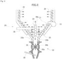
- FIG. 3 is an explanatory view illustrating a configuration of a bottom portion of a primary combustion chamber of the powder fuel combustion apparatus according to the present embodiment.
- powdered char that is made from waste plastic produced using the carbonized fuel production apparatus disclosed in Patent Literature 2 is used as powder fuel.
- a powder fuel combustion apparatus 1 is a combustion apparatus adopted in a power generation system 2 using powder fuel F, as illustrated in FIG. 1 .
- the power generation system 2 includes, in addition to the powder fuel combustion apparatus 1, a boiler 3, a dust collecting device 4, a power generating device 5, a smokestack 6, and a controller 7 for controlling the devices.
- the powder fuel combustion apparatus 1 includes, as illustrated in FIG. 1 , a fuel supply device 10, a primary combustion chamber 20, a secondary combustion chamber 50, an air supply/ash discharge device 32, and a cyclone dust collector 60. An outlet of the cyclone dust collector 60 is connected to the boiler 3.
- the primary combustion chamber 20 has an overall cylindrical shape according to the present embodiment, and it is composed of a ceiling portion 21 positioned at an upper portion thereof, a body portion 22 positioned at a lower side of the ceiling portion 21, and a bottom portion 23 positioned at a lower side of the body portion 22.
- a primary exhaust port 24 through which a flammable gas or a combustion gas generated in the primary combustion chamber 20 is discharged is formed to the ceiling portion 21. Further, a first temperature sensor 25 for detecting the temperature of a combustion gas generated in the primary combustion chamber 20 is provided in the primary exhaust port 24.
- the primary exhaust port 24 can be formed on a top panel of the ceiling portion 21 as illustrated in FIG. 1 , or it can be formed on a side wall thereof.
- the fuel supply device 10 is connected to the body portion 22.
- the fuel supply device 10 includes a fuel hopper 11 through which a powder fuel F is charged, a mixing pipe 12 in which the powder fuel F and combustion air are mixed, a fuel delivery device 13 for supplying the powder fuel F charged in the fuel hopper 11 to the mixing pipe 12 by an arbitrary amount of supply, a blower for fuel 14 for supplying combustion air to the mixing pipe 12, and a burner port 15 disposed at a tip portion of the mixing pipe 12.
- a hopper injection nozzle 16 having a tubular shape and extending in a vertical direction is disposed in a center of the fuel hopper 11.
- the hopper injection nozzle 16 is a tubular shaped member having upper and lower end potions opened, and a plurality of injection ports 16a are formed on a side surface thereof through which air is injected.
- a lower end portion of the hopper injection nozzle 16 is disposed toward an opening portion 11a of the fuel hopper 11.
- a hopper air supply device 18 composed of an air compressor 70, a solenoid valve for fuel 17 and an air supply pipe for fuel 16b is connected to the hopper injection nozzle 16.
- the fuel delivery device 13 of the fuel supply device 10 delivers the powder fuel F by rotation of a rotary valve 13b inside a case 13a having a cylindrical shape.
- An amount of delivery per time of fuel is controlled by subjecting a motor not shown to inverter control and adjusting a rotational frequency of the rotary valve 13b.
- An amount of air blow of the blower for fuel 14 of the fuel supply device 10 can also be adjusted by subjecting a motor not shown to inverter control.
- An air-fuel ratio of fuel blown out through the burner port 15 can be changed by adjusting the amount of delivery of the powder fuel F of the fuel delivery device 13 and the amount of air blow of the blower for fuel 14.
- a plurality of primary air supply ports 26 for supplying primary combustion air into the primary combustion chamber 20 are provided on a peripheral wall of the body portion 22. Air is supplied to the primary air supply ports 26 from a primary air blower 27 which is a primary air supply device disposed on an outer side of the body portion 22.
- a steam inlet port 28 and a vent gas inlet port 29 are provided on an upper position of the body portion 22. These inlet ports can be used to introduce steam and vent gas into the primary combustion chamber 20 as needed.
- steam steam containing smell components recovered during production of fuel by a fuel production apparatus disclosed in Patent Literature 2 and the like can be introduced.
- vent gas gas recovered during production of fuel by the fuel production apparatus disclosed in Patent Literature 2 can be used.
- the body portion 22 is provided with a stabilizing burner 30 that helps combustion inside the primary combustion chamber 20, and a stabilizing solenoid valve 30a for supplying air to the stabilizing burner 30.
- a vent oil that has been recovered during fuel production by the fuel production apparatus disclosed in Patent Literature 2 is used as the fuel for the stabilizing burner 30.
- An inclined portion 23a that is inclined to narrow toward the lower direction from a wall surface of the body portion 22 is formed at the bottom portion 23 of the primary combustion chamber 20, and an ash outlet 23b is formed below the inclined portion 23a.
- the inclined portion 23a is provided with a plurality of bottom portion air supply ports 31 that introduce combustion air to the interior. Air is supplied from the primary air blower 27 to the bottom portion air supply ports 31.
- the bottom portion 23 is further provided with the air supply/ash discharge device 32 that is arranged in the interior of the inclined portion 23a and an ignition burner 33 that ignites the powder fuel F charged in the bottom portion 23.
- the fuel used in the ignition burner 33 can be kerosene or heavy oil and the like.
- the air supply/ash discharge device 32 includes a bottom portion air injection nozzle 34 and an ash delivery device 35.
- the bottom portion air injection nozzle 34 is a tubular shaped member extending in the vertical direction, and which is positioned approximately at a center of the inclined portion 23a.
- the bottom portion air injection nozzle 34 has its upper and lower ends opened, and a plurality of injection ports 34a through which air is injected are provided on the side surface thereof.
- the lower end portion of the bottom portion air injection nozzle 34 is arranged toward the ash outlet 23b.
- An injection air supply device 36 composed of the air compressor 70 and a bottom portion solenoid valve 37, and a bottom portion air supply pipe 38 are connected to the bottom portion air injection nozzle 34. Air for injection is supplied from the injection air supply device 36 to the bottom portion air injection nozzle 34.
- the ash delivery device 35 delivers ashes by having a rotary valve 35b rotate inside a case 35a having a tubular shape. Further, a water spray nozzle 39 for injecting water into a lower portion of the case 35a is provided on the ash delivery device 35. When water is injected through the water spray nozzle 39, the ashes inside the case 35a are cooled and the ashes are gathered by water, by which the ashes fall downward without being scattered.
- An ash receiver 40 is arranged below the ash outlet 23b to pool the ashes discharged through the ash outlet 23b.
- the ash receiver 40 is capable of being moved by a moving unit such as a forklift from the position below the ash outlet 23b to an ash recovery location.
- the powder fuel combustion apparatus 1 is provided with a vent oil tank 71 for supplying vent oil serving as fuel to the stabilizing burner 30, a water tank 72 for supplying water to the water spray nozzle 39, and so on.
- the secondary combustion chamber 50 is a combustion chamber having a cylindrical shape to which is connected the primary exhaust port 24 through which combustion gas of the primary combustion chamber 20 is introduced.
- a secondary burner 51 for igniting combustion gas is provided near a connecting portion of the primary exhaust port 24.
- a plurality of secondary air supply ports 52 for supplying secondary combustion air for performing secondary combustion are provided to the peripheral wall of the secondary combustion chamber 50. Air is supplied to the secondary air supply ports 52 from a secondary air blower 53 serving as a secondary air supply device.
- a secondary exhaust port 54 which is connected to the cyclone dust collector 60 is provided downstream of the secondary combustion chamber 50.
- the secondary exhaust port 54 is provided with a second temperature sensor 55 for detecting temperature of combustion gas of the secondary combustion chamber 50.
- a cyclone recovery device 61 is provided below the cyclone dust collector 60.
- the cyclone recovery device 61 is composed of a rotary valve 62 and a screw conveyor 63. Powder dust recovered in the cyclone dust collector 60 is once again returned to the primary combustion chamber 20 by the cyclone recovery device 61 and subjected to combustion.
- the boiler 3 according to the power generation system 2 of the present embodiment is an apparatus that generates superheated vapor and saturated vapor by heat from the exhaust gas subjected to dust collection processing by the cyclone dust collector 60. According to present embodiment, the boiler 3 performs heat recovery from the exhaust gas of approximately 600 °C and lowers the outlet temperature of exhaust gas to approximately 200 °C.
- the power generating device 5 is a device that generates electricity by rotating a turbine not shown by steam that has been generated in the boiler 3.
- a generally used device is adopted as the power generating device 5.
- the steam generated in the boiler 3 can be utilized not only in the power generating device 5 but also in auxiliary facilities such as a heating equipment.
- the dust collecting device 4 is provided downstream of the boiler 3.
- a bag filter and the like being widely used in general can be adopted as the dust collecting device 4.
- a device for lowering the gas temperature and the like can be installed as needed before the bag filter.
- other types of dust collectors such as a centrifugal type dust collector, an electric dust collector, or a gravity type dust collector can be adopted as the dust collecting device 4. It may be possible to omit the dust collecting device 4 itself, depending on the scale of the power generation system 2 or the type of fuel being combusted.
- a suction fan not shown is provided on the smokestack 6, and the exhaust gas generated in the powder fuel combustion apparatus 1 is sucked to the smokestack 6 and released to the exterior.
- the suction fan is also driven by inverter control, and the rotational frequency thereof is controlled by signals from the controller 7.
- the controller 7 is a so-called control panel that includes various operation switches, an indicator showing operating states of respective devices, and a computer for controlling the respective devices (all of which are not shown).
- the computer of the controller 7 is equipped with a CPU, a storage device, a communication device and so on (all of which are not shown), and the storage device stores programs for executing operation of the power generation system 2 including the powder fuel combustion apparatus 1 according to the present embodiment.
- the combustion method according to the present embodiment is composed of a fuel charging step, an igniting step, a gasification combustion step, a direct combustion step, and an ember-ashing step.
- the respective steps are executed by programs stored in the controller 7.
- a fuel charging step is performed.
- a predetermined amount of powder fuel F is accumulated in the primary combustion chamber 20 using the fuel supply device 10.
- the amount of powder fuel F is set so that approximately one-third of a capacity of the primary combustion chamber 20 is filled.
- the predetermined amount should preferably be approximately one-fourth to one-half of the primary combustion chamber 20 considering operating efficiency of the powder fuel combustion apparatus 1, but it can be varied arbitrarily according to the property of the powder fuel F.
- the fuel supply device 10 is started in a state where the powder fuel F is charged in the fuel hopper 11 of the fuel supply device 10.
- the charging of the powder fuel F to the fuel hopper 11 can be controlled by the controller 7 using a conveyor, or by manually operating the conveyor or the like.
- the rotary valve 13b When the fuel supply device 10 is started by the controller 7, the rotary valve 13b is rotated and the powder fuel F in the fuel hopper 11 is conveyed to the lower part of the case 13a by the rotary valve 13b. In this state, air for injection is sent at a predetermined timing from the hopper air supply device 18 to the hopper injection nozzle 16 in the fuel hopper 11. Thereby, the powder fuel F in the fuel hopper 11 is conveyed to the lower part of the case 13a by the rotary valve 13b without causing bridging or the like.
- the timing for activating the hopper air supply device 18 can be varied arbitrarily according to the state of the powder fuel F, and for example, the hopper air supply device 18 can be activated every one to ten minutes or can be activated each time the powder fuel F is added to the fuel hopper 11.
- the operation of the blower for fuel 14 is also started, and air is supplied to the mixing pipe 12.
- the powder fuel F and the supplied air are mixed in the mixing pipe 12 and discharged frontward through the burner port 15.
- the ignition burner 33 and the stabilizing burner 30 are not activated in the primary combustion chamber 20, so that the powder fuel F discharged from the fuel supply device 10 is accumulated at the bottom portion 23 of the primary combustion chamber 20.
- the operation of the fuel supply device 10 is continued until approximately one-third of the capacity of the primary combustion chamber 20 is filled, and after a predetermined amount of the powder fuel F has been supplied, the operation of the fuel supply device 10 is stopped.
- the igniting step is performed.
- combustion of the secondary burner 51 of the secondary combustion chamber 50 is started, and the temperature inside the secondary combustion chamber 50 is raised.
- the ignition burner 33 is activated to ignite the powder fuel F accumulated in the primary combustion chamber 20. In this state, if ignition of the powder fuel F accumulated in the primary combustion chamber 20 has been confirmed via the first temperature sensor 25, the ignition burner 33 is stopped.
- the gasification combustion step a part of the powder fuel F charged during the fuel charging step is combusted in the primary combustion chamber 20 and generates flammable gas.
- Primary combustion air is supplied to the primary combustion chamber 20 through the primary air blower 27, the primary air supply ports 26 and the bottom portion air supply ports 31.
- an amount of air smaller than the amount of air necessary for complete combustion of the powder fuel F is supplied as the primary combustion air introduced to the primary combustion chamber 20. Therefore, in the primary combustion chamber 20, a portion of the powder fuel F is combusted and heats the surrounding powder fuel F to gradually expand the combustion range, so that flammable gas is generated from the powder fuel F.
- Air is supplied intermittently to the primary combustion chamber 20 from the bottom portion air injection nozzle 34 of the air supply/ash discharge device 32. Air is injected through upper and lower end portions and injection ports 34a of the bottom portion air injection nozzle 34. In this state, for example, control is performed to inject a minute amount of air for a predetermined time and to increase the amount of injection either regularly or irregularly. Specifically, a small amount of air that will not cause wind pressure that moves the powder fuel F near the bottom portion air injection nozzle 34 is injected for five minutes, and once every five minutes, strong air capable of agitating the powder fuel F around the bottom portion air injection nozzle 34 is injected.
- the injection of air is not limited to regular injection performed every five minutes, for example, and air can be injected normally at a weak wind pressure, wherein if the temperature inside the primary combustion chamber 20 becomes equal to or lower than a predetermined temperature, the injection of air can be performed at such a strength that the powder fuel F is agitated.
- air By injecting air intermittently through the upper and lower opening portions of the bottom portion air injection nozzle 34 and the injection ports 34a provided on the side walls thereof, the powder fuel F accumulated at the bottom portion 23 of the primary combustion chamber 20 is agitated and preferable combustion is performed.
- flammable gas from the primary combustion chamber 20 is discharged into the heated secondary combustion chamber 50 during the gasification combustion step, the flammable gas is ignited by the secondary burner 51, and complete combustion is performed inside the secondary combustion chamber 50.
- control is performed so that the combustion temperature inside the secondary combustion chamber 50 is set to 800 °C or higher, preferably 900 °C or higher.
- the secondary burner 51 stops operating if the temperature detected by the second temperature sensor becomes equal to the predetermined temperature or higher, but even thereafter, combustion in the secondary combustion chamber 50 is continued by the flammable gas from the primary combustion chamber 20.
- the controller 7 performs control so that the combustion temperature inside the secondary combustion chamber 50 is approximately constant.
- the control of combustion temperature inside the secondary combustion chamber 50 is performed by adjusting the amount of primary air supplied by the primary air blower 27 in a state where a constant amount of secondary air necessary for complete combustion of flammable gas is supplied from the secondary air blower 53.
- the combustion temperature inside the secondary combustion chamber 50 can be controlled by controlling combustion by the stabilizing burner 30. Meanwhile, even if steam is supplied from the steam inlet port 28 and vent gas is introduced through the vent gas inlet port 29, the combustion temperature inside the secondary combustion chamber 50 can be controlled by adjusting the amount of primary air supplied by the primary air blower 27.
- the exhaust gas is discharged through the secondary exhaust port 54 and passed through the cyclone dust collector 60 to be introduced to the boiler 3.
- the powder dust contained in the exhaust gas is separated and dropped to the bottom portion of the cyclone dust collector 60.
- the powder dust dropped to the bottom portion is returned to the primary combustion chamber 20 by the rotary valve 62 and the screw conveyor 63 of the cyclone recovery device 61 and subjected to combustion.
- the exhaust gas from which powder dust has been removed as described above has a high temperature in the secondary exhaust port 54, but it is subjected to heat exchange at the boiler 3 and the temperature thereof drops before being passed through the dust collecting device 4 and the smokestack 6 to be discharged to the outer air.
- the powder fuel F accumulated in the primary combustion chamber 20 is gradually switched from gasification combustion to direct combustion.
- the switching of the combustion state is determined based on the temperature inside the primary combustion chamber 20 and the temperature condition inside the secondary combustion chamber 50.
- the gradual switching from gasification combustion to direct combustion is detected at a timing at which the temperature of the secondary combustion chamber 50 starts to drop.
- the amount of primary air supplied by the primary air blower 27 is adjusted to make the combustion temperature inside the secondary combustion chamber 50 constant.
- the procedure advances to the direct combustion step.
- the powder fuel F accumulated in the bottom portion 23 of the primary combustion chamber 20 continues combustion by direct combustion.
- air is supplied through the bottom portion air supply ports 31 and air is also injected intermittently through the bottom portion air injection nozzle 34.
- the powder fuel F is supplied from the fuel supply device 10.
- the temperature inside the primary combustion chamber 20 is in a state exceeding the ignition temperature of the powder fuel F, so that the powder fuel F injected from the burner port 15 is ignited and continuous combustion is realized.
- the fuel supply device 10 serves as a burner for powder fuel.
- the powder fuel F injected from the fuel supply device 10 is supplied into the primary combustion chamber 20 while being combusted, wherein the combusted component is discharged as combustion gas to the secondary combustion chamber 50, and the yet-to-be-combusted portion is accumulated inside the primary combustion chamber 20 while being combusted. Further, the powder fuel F supplied into the primary combustion chamber 20 is continuously combusted by the combustion air supplied through the primary air supply ports 26 and the bottom portion air injection nozzle 34, and gradually ashed.
- the procedure advances to an ember-ashing step.
- the supply of powder fuel F by the fuel supply device 10 is stopped.
- combustion inside the primary combustion chamber 20 is performed only by the powder fuel F accumulated in the bottom portion 23 of the primary combustion chamber 20, and combustion is gradually transited from direct combustion to ember combustion, and when ember combustion is continued, the powder fuel F is gradually ashed.
- the ember-ashing step since combustion of powder fuel F advances to ember combustion, the remaining powder fuel F is gradually ashed, and in the end, it is almost completely ashed.
- the ashing of powder fuel F inside the primary combustion chamber 20 can be detected by detecting the temperature inside the primary combustion chamber 20 by the first temperature sensor 25.
- Ashes of the powder fuel F having been ashed are discharged to the exterior of the primary combustion chamber 20 by the ash delivery device 35 of the air supply/ash discharge device 32.
- the rotary valve 35b is rotated to discharge the ashes at the bottom portion 23 of the primary combustion chamber 20 through the ash outlet 23b to the exterior.
- air is injected strongly through the bottom portion air injection nozzle 34 intermittently, so that the ashes accumulated in the bottom portion 23 is discharged smoothly to the exterior.
- Water is injected through the water spray nozzle 39 at the lower portion of the case 35a to the ashes discharged from the ash outlet 23b, so that the temperature of the ashes in the case 35a is lowered and ashes are gathered by water, thereby dropping down without being scattered.
- the ash receiver 40 is arranged below the ash outlet 23b to store the ashes discharged through the ash outlet 23b and deliver the ashes to a recovery location via a forklift and the like as needed.
- the powder fuel combustion apparatus 1 of the present invention air is injected intermittently to the powder fuel F at the bottom portion 23 of the primary combustion chamber 20 through the bottom portion air injection nozzle 34 of the air supply/ash discharge device 32, so that the powder fuel F can be combusted and ashed infallibly without being accumulated at the bottom of the furnace, and discharged to the exterior of the primary combustion chamber 20. Therefore, the powder fuel combustion apparatus 1 according to the present invention can combust the powder fuel F infallibly and perform energy recovery of the power generating device 5 efficiently.
Landscapes
- Engineering & Computer Science (AREA)
- Chemical & Material Sciences (AREA)
- Combustion & Propulsion (AREA)
- Mechanical Engineering (AREA)
- General Engineering & Computer Science (AREA)
- Combustion Of Fluid Fuel (AREA)
- Solid-Fuel Combustion (AREA)
- Gasification And Melting Of Waste (AREA)
Claims (8)
- Verbrennungsvorrichtung (1) zum Verbrennen eines Pulverkraftstoffs, die Folgendes umfasst:eine primäre Verbrennungskammer (20), die konfiguriert ist, den Pulverkraftstoff in ihrem Innenraum zu verbrennen, und eine sekundäre Verbrennungskammer (50), die konfiguriert ist, ein aus der primären Verbrennungskammer (20) austretendes Verbrennungsgas zu verbrennen,wobei die primäre Verbrennungskammer (20) eine Kraftstoffzufuhrvorrichtung (10), die konfiguriert ist, den Pulverkraftstoff ihrem Innenraum zuzuführen, eine primäre Luftzufuhröffnung (26), die konfiguriert ist, Luft ihrem Innenraum zuzuführen, und einen Zündbrenner (33), der konfiguriert ist, den Pulverkraftstoff in ihrem Innenraum zu zünden, umfasst,wobei ein Bodenabschnitt der primären Verbrennungskammer (20) einen geneigten Abschnitt (23a), der so geneigt ist, dass er sich nach unten verjüngt, eine Bodenabschnitt-Luftzufuhröffnung (31), die konfiguriert ist, dass sie Luft einem Innenraum zuführt, einen Ascheauslass (23b), der an einer unteren Position des geneigten Abschnitts (23a) vorgesehen ist, und eine Bodenabschnitt-Lufteinspritzdüse (34) umfasst, die eine Röhrenform aufweist und in einer vertikalen Richtung angeordnet ist, wobei die Bodenabschnitt-Lufteinspritzdüse (34) Öffnungen, die an einem oberen und einem unteren Ende davon ausgebildet sind, wobei das untere Ende in Richtung des Ascheauslasses (23b) angeordnet ist, umfasst und Luft dem Innenraum zuführt,wobei die sekundäre Verbrennungskammer (50) einen sekundären Brenner (51), der konfiguriert ist, ihren Innenraum zu erwärmen und ein aus der primären Verbrennungskammer (20) austretendes Verbrennungsgas zu zünden, und eine sekundäre Luftzufuhröffnung (52), die konfiguriert ist, ihrem Innenraum Verbrennungsluft zuzuführen, umfasst,eine primäre Luftzufuhrvorrichtung (27), die konfiguriert ist, Luft der primären Luftzufuhröffnung (26) und der Bodenabschnitt-Luftzufuhröffnung (31) zuzuführen, eine Injektionsluftzufuhrvorrichtung (36), die konfiguriert ist, Luft der Bodenabschnitt-Lufteinspritzdüse (34) zuzuführen, und eine sekundäre Luftzufuhrvorrichtung (53), die konfiguriert ist, Luft der sekundären Luftzufuhröffnung (52) zuzuführen, undeine Steuereinheit (7), die konfiguriert ist, den Betrieb der Kraftstoffzufuhrvorrichtung (10), des Zündbrenners (33), des sekundären Brenners (51), der primären Luftzufuhrvorrichtung (27), der Injektionsluftzufuhrvorrichtung (36) und der sekundären Luftzufuhrvorrichtung (53) zu steuern,wobei die Steuereinheit (7) konfiguriert ist,eine vorgegebene Menge des Pulverkraftstoffs in der primären Verbrennungskammer (20) durch die Kraftstoffzufuhrvorrichtung (10) anzusammeln,den angesammelten Pulverkraftstoff unter Verwendung des Zündbrenners (33) zu zünden und den sekundären Brenner (51) zu aktivieren, um den Innenraum der sekundären Verbrennungskammer (50) zu erwärmen,beim Durchführen einer Vergasungsverbrennung des angesammelten Pulverkraftstoffs die primäre Luftzufuhrvorrichtung (27) und die Injektionsluftzufuhrvorrichtung (36) zu aktivieren, um eine Luftmenge, die kleiner ist als eine Luftmenge, die für eine vollständige Verbrennung des angesammelten Pulverkraftstoffs erforderlich ist, durch die primäre Luftzufuhröffnung (26), die Bodenabschnitt-Luftzufuhröffnung (31) und die Bodenabschnitt-Lufteinspritzdüse (34) zuzuführen, um brennbares Gas innerhalb der primären Verbrennungskammer (20) zu erzeugen,beim Durchführen einer direkten Verbrennung des angesammelten Pulverkraftstoffs die primäre Luftzufuhrvorrichtung (27) und die Injektionsluftzufuhrvorrichtung (36) zu aktivieren, um eine für die direkte Verbrennung des Pulverkraftstoffs erforderliche Luftmenge durch die primäre Luftzufuhröffnung (26), die Bodenabschnitt-Luftzufuhröffnung (31) und die Bodenabschnitt-Lufteinspritzdüse (34) der primären Verbrennungskammer (20) zuzuführen, und die Kraftstoffzufuhrvorrichtung (10) zu aktivieren, um den Pulverkraftstoff der primären Verbrennungskammer (20) zuzuführen, um den Pulverkraftstoff zu verbrennen, und die Kraftstoffzufuhrvorrichtung (10) als Brenner zu aktivieren, undbeim Durchführen einer Vergasungsverbrennung des angesammelten Pulverkraftstoffs und Durchführen der direkten Verbrennung des angesammelten Pulverkraftstoffs die sekundäre Luftzufuhrvorrichtung (53) zu aktivieren, um eine zur vollständigen Verbrennung des brennbaren Gases erforderliche Menge an Sekundärverbrennungsluft durch die sekundäre Luftzufuhrvorrichtung (53) zuzuführen, um das brennbare Gas zu verbrennen.
- Vorrichtung (1) zur Verbrennung von Pulverkraftstoff nach Anspruch 1,
wobei beim Durchführen der Glutverbrennung und Veraschen des Pulverkraftstoffs in der primären Verbrennungskammer (20) die Kraftstoffzufuhr durch die Kraftstoffzufuhrvorrichtung (10) gestoppt wird und die Luftzufuhr aus der Bodenabschnitt-Lufteinspritzdüse (34) ebenfalls gestoppt wird. - Vorrichtung (1) zur Verbrennung von Pulverkraftstoff gemäß Anspruch 1 oder 2,
wobei beim Durchführen einer Vergasungsverbrennung des angesammelten Pulverkraftstoffs und beim Durchführen einer direkten Verbrennung des angesammelten Pulverkraftstoffs die Steuereinheit (7) konfiguriert ist, die Injektionsluftzufuhrvorrichtung (36) so zu steuern, dass Luft in einer Injektionsmenge eingespritzt wird, die in der Lage ist, den Pulverkraftstoff entweder regelmäßig oder unregelmäßig zu der Bodenabschnitt-Lufteinspritzdüse (34) zu bewegen. - Vorrichtung (1) zur Verbrennung von Pulverkraftstoff nach einem der Ansprüche 1 bis 3,wobei die Kraftstoffzufuhrvorrichtung (10) einen Kraftstofftrichter (11), durch den der Pulverkraftstoff geladen wird, eine Trichtereinspritzdüse (16), die in einer vertikalen Richtung in dem Kraftstofftrichter (11) angeordnet ist, um Luft zumindest in eine untere Richtung davon einzuspritzen, eine Trichterluftzufuhrvorrichtung (18), die konfiguriert ist, Luft der Trichtereinspritzdüse (16) zuzuführen, eine Kraftstofffördervorrichtung (13), die an einer unteren Richtung der Trichtereinspritzdüse (16) angeordnet ist und den Pulverkraftstoff in die untere Richtung liefert, ein Mischrohr (12), in dem der Pulverkraftstoff und Luft gemischt werden, und ein Kraftstoffgebläse (14), das konfiguriert ist, Luft dem Mischrohr (12) zuzuführen, umfasst, undbeim Zuführen des Pulverkraftstoffs der primären Verbrennungskammer (20) die Steuereinheit (7) konfiguriert ist, dass sie das Kraftstoffgebläse (14) und auch die Kraftstofffördervorrichtung (13) aktiviert, den Pulverkraftstoff und die von dem Kraftstoffgebläse (14) zugeführte Luft in einem Innenraum des Mischrohrs (12) mischt und den Pulverkraftstoff von dem Mischrohr (12) der primären Verbrennungskammer (20) zuführt, und die Trichterluftzufuhrvorrichtung (18) zu einem vorbestimmten Zeitpunkt aktiviert, um Luft durch die Trichtereinspritzdüse (16) einzuspritzen.
- Verbrennungsverfahren des Verbrennens eines Pulverkraftstoffs mittels einer Vorrichtung (1) zur Verbrennung von Pulverkraftstoff, umfassend die folgenden Schritte:einen Kraftstoffladeschritt, einen Zündschritt, einen Vergasungsverbrennungsschritt, einen Direktverbrennungsschritt und einen Glutveraschungsschritt,wobei die Vorrichtung (1) zur Verbrennung von Pulverkraftstoff Folgendes umfassteine primäre Verbrennungskammer (20), die konfiguriert ist, den Pulverkraftstoff in ihrem Innenraum zu verbrennen, und eine sekundäre Verbrennungskammer (50), die konfiguriert ist, ein aus der primären Verbrennungskammer (20) austretendes Verbrennungsgas zu verbrennen,wobei die primäre Verbrennungskammer (20) eine Kraftstoffzufuhrvorrichtung (10), die konfiguriert ist, den Pulverkraftstoff ihrem Innenraum zuzuführen, eine primäre Luftzufuhröffnung (26), die konfiguriert ist, Luft ihrem Innenraum zuzuführen, und einen Zündbrenner (33), der konfiguriert ist, den Pulverkraftstoff in ihrem Innenraum zu zünden, umfasst,wobei ein Bodenabschnitt der primären Verbrennungskammer (20) einen geneigten Abschnitt (23a), der so geneigt ist, dass er sich nach unten verjüngt, eine Bodenabschnitt-Luftzufuhröffnung (31), die konfiguriert ist, dass sie Luft einem Innenraum zuführt, einen Ascheauslass (23b), der an einer unteren Position des geneigten Abschnitts (23a) vorgesehen ist, und eine Bodenabschnitt-Lufteinspritzdüse (34), die eine Röhrenform aufweist und in einer vertikalen Richtung angeordnet ist, umfasst, wobei die Bodenabschnitt-Lufteinspritzdüse (34) Öffnungen, die an einem oberen und einem unteren Ende davon ausgebildet sind, wobei das untere Ende in Richtung des Ascheauslasses (23b) angeordnet ist, umfasst und Luft dem Innenraum zuführt,wobei die sekundäre Verbrennungskammer (50) einen sekundären Brenner (51), der konfiguriert ist, ihren Innenraum zu erwärmen, und eine sekundäre Luftzufuhröffnung (52), die konfiguriert ist, ihrem Innenraum Verbrennungsluft zuzuführen, umfasst,eine primäre Luftzufuhrvorrichtung (27), die konfiguriert ist, Luft der primären Luftzufuhröffnung (26) und der Bodenabschnitt-Luftzufuhröffnung (31) zuzuführen, eine Injektionsluftzufuhrvorrichtung (36), die konfiguriert ist, Luft der Bodenabschnitt-Lufteinspritzdüse (34) zuzuführen, und eine sekundäre Luftzufuhrvorrichtung (53), die konfiguriert ist, Luft der sekundären Luftzufuhröffnung (52) zuzuführen, undeine Steuereinheit (7), die konfiguriert ist, den Betrieb der Kraftstoffzufuhrvorrichtung (10), des Zündbrenners (33), des sekundären Brenners (51), der primären Luftzufuhrvorrichtung (27), der Injektionsluftzufuhrvorrichtung (36) und der sekundären Luftzufuhrvorrichtung (53) zu steuern,wobei die Steuereinheit (7) konfiguriert ist,eine vorgegebene Menge des Pulverkraftstoffs in der primären Verbrennungskammer (20) durch die Kraftstoffzufuhrvorrichtung (10) in dem Kraftstoffladeschritt anzusammeln,den Innenraum der sekundären Verbrennungskammer (50) durch den sekundären Brenner (51) zu erwärmen und, nachdem der Innenraum der sekundären Verbrennungskammer (50) eine vorbestimmte Temperatur erreicht hat, den angesammelten Pulverkraftstoff unter Verwendung des Zündbrenners (33) in dem Zündschritt zu zünden,eine Luftmenge, die kleiner ist als die Luftmenge, die für eine vollständige Verbrennung des angesammelten Pulverkraftstoffs notwendig ist, durch die primäre Luftzufuhröffnung (26), die Bodenabschnitt-Luftzufuhröffnung (31) und die Bodenabschnitt-Lufteinspritzdüse (34) zuzuführen, um brennbares Gas in der primären Verbrennungskammer (20) zu erzeugen, das brennbare Gas in die sekundäre Verbrennungskammer (50) zu überführen und eine vollständige Verbrennung des brennbaren Gases durch Zuführen von Luft für die sekundäre Verbrennung durch die sekundäre Luftzufuhröffnung (52) in dem Vergasungsverbrennungsschritt durchzuführen,die primäre Luftzufuhrvorrichtung (27) und die Injektionsluftzufuhrvorrichtung (36) zu aktivieren, um der primären Verbrennungskammer (20) eine für die direkte Verbrennung des Pulverkraftstoffs erforderliche Luftmenge durch die primäre Luftzufuhröffnung (26), die Bodenabschnitt-Luftzufuhröffnung (31) und die Bodenabschnitt-Lufteinspritzdüse (34) zuzuführen, die Kraftstoffzufuhrvorrichtung (10) zu aktivieren, um den Pulverkraftstoff der primären Verbrennungskammer (20) zuzuführen und eine Verbrennung des Pulverkraftstoffs durchzuführen, um die Kraftstoffzufuhrvorrichtung (10) als Brenner zu aktivieren, Verbrennungsgas, das aus der primären Verbrennungskammer (20) ausgetragen wird, in die sekundäre Verbrennungskammer (50) zu überführen und eine vollständige Verbrennung des Verbrennungsgases durch Zuführen von Luft für die Sekundärverbrennung durch die sekundäre Luftzufuhröffnung (52) in dem Direktverbrennungsschritt durchzuführen, unddie Kraftstoffzufuhr durch die Kraftstoffzufuhrvorrichtung (10) zu stoppen und eine Glutverbrennung und Veraschung des in der primären Verbrennungskammer (20) verbleibenden Pulverkraftstoffs in dem Glutveraschungsschritt durchzuführen.
- Pulverkraftstoff-Verbrennungsverfahren gemäß Anspruch 5,
wobei in dem Glutveraschungsschritt die Luftzufuhr aus der Bodenabschnitt-Lufteinspritzdüse (34) gestoppt wird. - Pulverkraftstoff-Verbrennungsverfahren gemäß einem der Ansprüche 5 oder 6,
wobei die Steuereinheit (7) in dem Vergasungsverbrennungsschritt und in dem Direktverbrennungsschritt konfiguriert ist, die Injektionsluftzufuhrvorrichtung (36) so zu steuern, dass Luft in einer Injektionsmenge eingespritzt wird, die in der Lage ist, den Pulverkraftstoff entweder regelmäßig oder unregelmäßig zu der Bodenabschnitt-Lufteinspritzdüse (34) zu bewegen. - Pulverkraftstoff-Verbrennungsverfahren nach einem der Ansprüche 5 bis 7,wobei die Kraftstoffzufuhrvorrichtung (10) einen Kraftstofftrichter (11), durch den der Pulverkraftstoff geladen wird, eine Trichtereinspritzdüse (16), die in einer vertikalen Richtung in dem Kraftstofftrichter (11) angeordnet ist, um Luft zumindest in eine untere Richtung davon einzuspritzen, eine Trichterluftzufuhrvorrichtung (18), die konfiguriert ist, Luft der Trichtereinspritzdüse (16) zuzuführen, eine Kraftstofffördervorrichtung (13), die an einer unteren Richtung der Trichtereinspritzdüse (16) angeordnet ist und den Pulverkraftstoff in die untere Richtung liefert, ein Mischrohr (12), in dem der Pulverkraftstoff und Luft gemischt werden, und ein Kraftstoffgebläse (14), das konfiguriert ist, Luft dem Mischrohr (12) zuzuführen, umfasst, unddie Steuereinheit (7) in dem Kraftstoffladeschritt und in dem Direktverbrennungsschritt konfiguriert ist, dass sie das Kraftstoffgebläse (14) und auch die Kraftstofffördervorrichtung (13) aktiviert, den Pulverkraftstoff und die von dem Kraftstoffgebläse (14) zugeführte Luft in einem Innenraum des Mischrohrs (12) mischt und den Pulverkraftstoff von dem Mischrohr (12) der primären Verbrennungskammer (20) zuführt, und die Trichterluftzufuhrvorrichtung (18) zu einem vorbestimmten Zeitpunkt aktiviert, um Luft durch die Trichtereinspritzdüse (16) einzuspritzen.
Applications Claiming Priority (2)
| Application Number | Priority Date | Filing Date | Title |
|---|---|---|---|
| JP2019036448A JP6989876B2 (ja) | 2019-02-28 | 2019-02-28 | 粉体燃料燃焼装置及び燃焼方法 |
| PCT/JP2020/008123 WO2020175639A1 (ja) | 2019-02-28 | 2020-02-27 | 粉体燃料燃焼装置及び燃焼方法 |
Publications (3)
| Publication Number | Publication Date |
|---|---|
| EP3933264A1 EP3933264A1 (de) | 2022-01-05 |
| EP3933264A4 EP3933264A4 (de) | 2022-11-30 |
| EP3933264B1 true EP3933264B1 (de) | 2024-10-02 |
Family
ID=72239626
Family Applications (1)
| Application Number | Title | Priority Date | Filing Date |
|---|---|---|---|
| EP20762202.8A Active EP3933264B1 (de) | 2019-02-28 | 2020-02-27 | Pulverbrennstoffverbrennungsvorrichtung und verbrennungsverfahren |
Country Status (9)
| Country | Link |
|---|---|
| US (1) | US20220120441A1 (de) |
| EP (1) | EP3933264B1 (de) |
| JP (1) | JP6989876B2 (de) |
| KR (1) | KR102540051B1 (de) |
| CN (1) | CN113544433B (de) |
| BR (1) | BR112021017044A2 (de) |
| CA (1) | CA3130559C (de) |
| TW (1) | TWI740396B (de) |
| WO (1) | WO2020175639A1 (de) |
Families Citing this family (1)
| Publication number | Priority date | Publication date | Assignee | Title |
|---|---|---|---|---|
| FR3166956A1 (fr) * | 2024-10-01 | 2026-04-03 | Rosi | Four de pyrolyse pour le démantèlement de modules photovoltaïques et procédé de pyrolyse associé |
Family Cites Families (38)
| Publication number | Priority date | Publication date | Assignee | Title |
|---|---|---|---|---|
| JPS35592B1 (de) * | 1958-01-10 | 1960-01-30 | ||
| JPS5380836A (en) * | 1976-12-27 | 1978-07-17 | Hokkaido Sugar Co | Method of dustless combustion and combustion furnace therefor |
| US4092094A (en) * | 1977-02-25 | 1978-05-30 | Lingl Corporation | Method and apparatus for the controlled distribution of powdered solid fuel to burning units |
| JPS56916A (en) * | 1979-06-15 | 1981-01-08 | Hokkaido Togyo Kk | Method and apparatus for generating hot blast for incineration of chaff |
| DE3130813A1 (de) * | 1981-08-04 | 1983-03-24 | Imai, Takeshi, São Paulo | Vorrichtung zum vergasen von kohle, insbesondere vonholzkohle |
| JPS61213406A (ja) * | 1985-03-18 | 1986-09-22 | Takuma Co Ltd | 蒸気ボイラ |
| JP2951493B2 (ja) * | 1992-11-19 | 1999-09-20 | 株式会社マルコシエンジニアリング | 高分子系廃棄物用乾留ガス化炉 |
| JP3017661B2 (ja) * | 1994-07-13 | 2000-03-13 | 株式会社キンセイ産業 | 廃棄物の乾留ガス化焼却処理装置 |
| JP2957941B2 (ja) * | 1996-03-01 | 1999-10-06 | 有限会社伊勢工業所 | 焼却装置 |
| US6712496B2 (en) * | 2001-07-26 | 2004-03-30 | The Procter & Gamble Company | Auger fed mixer apparatus and method of using |
| JP3891958B2 (ja) | 2003-05-23 | 2007-03-14 | 三菱重工業株式会社 | 燃焼装置及び方法 |
| JP2005291539A (ja) | 2004-03-31 | 2005-10-20 | Babcock Hitachi Kk | バイオマス燃料の前処理及び混焼方法と装置 |
| US20080264310A1 (en) * | 2005-11-22 | 2008-10-30 | Clean Combustion Technologies, Llc | Combustion Method and System |
| JP4830140B2 (ja) * | 2006-03-31 | 2011-12-07 | Dowaエコシステム株式会社 | 燃焼制御方法及び焼却装置 |
| JP2008139010A (ja) * | 2006-11-09 | 2008-06-19 | Kokubun Nojo Kk | 燃焼装置 |
| JP2008286451A (ja) * | 2007-05-16 | 2008-11-27 | Kiyomi Yoshimura | バイオマス燃料の燃焼装置 |
| CN201262392Y (zh) * | 2008-07-29 | 2009-06-24 | 新疆电力科学研究院 | 一种煤粉锅炉防结焦的二次风燃烧器 |
| US8833276B2 (en) * | 2009-02-06 | 2014-09-16 | William Hunkyun Bang | Burner system for waste plastic fuel |
| JP5437734B2 (ja) * | 2009-08-07 | 2014-03-12 | 株式会社荏原製作所 | 燃焼式排ガス処理装置 |
| CN201539876U (zh) * | 2009-08-23 | 2010-08-04 | 宁波市镇海捷登应用技术研究所 | 一种炉子的助燃装置 |
| JP5568394B2 (ja) * | 2010-07-06 | 2014-08-06 | 榮 村田 | 焼却装置 |
| JP5774879B2 (ja) | 2011-03-07 | 2015-09-09 | 株式会社御池鐵工所 | 炉床構造及び燃焼炉 |
| JP3168444U (ja) * | 2011-04-01 | 2011-06-09 | 大沼 上 | 薪ストーブ |
| KR101220200B1 (ko) * | 2011-05-02 | 2013-01-09 | 류승우 | 고체연료 연소장치 |
| KR101399977B1 (ko) * | 2012-08-20 | 2014-05-28 | 김상권 | 클링커 제거장치를 구비한 연소장치 |
| CN103267280B (zh) * | 2013-05-30 | 2017-03-15 | 重庆富燃科技股份有限公司 | 采用富氧微油燃烧方式降低煤粉锅炉氮氧化物的方法 |
| RU2534652C1 (ru) * | 2013-08-13 | 2014-12-10 | Закрытое акционерное общество "ЗиО-КОТЭС" | Способ сжигания кавитационного водоуглеродного топлива из нефтяного кокса в топке кипящего слоя инертного материала и схема для его осуществления |
| CN203462010U (zh) * | 2013-09-11 | 2014-03-05 | 湖南人文科技学院 | 冷轧废矿物油气化炉 |
| JP6198572B2 (ja) * | 2013-10-29 | 2017-09-20 | 日工株式会社 | 固形燃料を主燃料とする熱風発生炉 |
| CN203668319U (zh) * | 2013-12-04 | 2014-06-25 | 汪稚昊 | 一种生物质气化装置 |
| CN204388043U (zh) * | 2014-12-10 | 2015-06-10 | 石家庄新华能源环保科技股份有限公司 | 一种焦粉燃烧装置 |
| JP6526499B2 (ja) * | 2015-06-29 | 2019-06-05 | 株式会社神鋼環境ソリューション | バーナ |
| JP6596351B2 (ja) | 2016-02-15 | 2019-10-23 | 三菱日立パワーシステムズ株式会社 | ボイラ |
| CN107543146B (zh) * | 2016-06-24 | 2020-06-23 | 荏原环境工程株式会社 | 燃烧装置以及锅炉 |
| JP2019172713A (ja) | 2016-10-17 | 2019-10-10 | ジェイアンドジー テクノロジーズ, エルエルシーJ&G Technologies, LLC | 炭化燃料製造装置及び炭化燃料製造方法 |
| JP2018087656A (ja) * | 2016-11-29 | 2018-06-07 | 有限会社長岡鉄工所 | 焼成炭化装置 |
| JP2018179336A (ja) | 2017-04-06 | 2018-11-15 | 株式会社Ihi環境エンジニアリング | 燃焼装置 |
| CN207196473U (zh) * | 2017-09-22 | 2018-04-06 | 郑州三众耐磨技术有限公司 | 具有一定防磨作用的cfb锅炉 |
-
2019
- 2019-02-28 JP JP2019036448A patent/JP6989876B2/ja not_active Expired - Fee Related
-
2020
- 2020-02-27 KR KR1020217030946A patent/KR102540051B1/ko active Active
- 2020-02-27 EP EP20762202.8A patent/EP3933264B1/de active Active
- 2020-02-27 WO PCT/JP2020/008123 patent/WO2020175639A1/ja not_active Ceased
- 2020-02-27 US US17/310,835 patent/US20220120441A1/en not_active Abandoned
- 2020-02-27 TW TW109106489A patent/TWI740396B/zh active
- 2020-02-27 BR BR112021017044A patent/BR112021017044A2/pt not_active Application Discontinuation
- 2020-02-27 CN CN202080015239.XA patent/CN113544433B/zh not_active Expired - Fee Related
- 2020-02-27 CA CA3130559A patent/CA3130559C/en active Active
Also Published As
| Publication number | Publication date |
|---|---|
| CN113544433B (zh) | 2024-03-26 |
| JP6989876B2 (ja) | 2022-01-12 |
| TWI740396B (zh) | 2021-09-21 |
| EP3933264A1 (de) | 2022-01-05 |
| CN113544433A (zh) | 2021-10-22 |
| JP2020139702A (ja) | 2020-09-03 |
| WO2020175639A1 (ja) | 2020-09-03 |
| EP3933264A4 (de) | 2022-11-30 |
| KR20210131409A (ko) | 2021-11-02 |
| TW202037847A (zh) | 2020-10-16 |
| CA3130559C (en) | 2024-01-16 |
| CA3130559A1 (en) | 2020-09-03 |
| BR112021017044A2 (pt) | 2021-11-16 |
| US20220120441A1 (en) | 2022-04-21 |
| KR102540051B1 (ko) | 2023-06-08 |
Similar Documents
| Publication | Publication Date | Title |
|---|---|---|
| US20180051877A1 (en) | Ash sintering gasifier | |
| CA2815325C (en) | Method and system for delivering heat through gasification of biomass | |
| JP5410694B2 (ja) | 可燃性廃棄物の処理装置 | |
| JP5611418B2 (ja) | ガス化溶融システムの燃焼制御方法及び該システム | |
| CA3130559C (en) | Powder fuel combustion apparatus and combustion method | |
| WO1992014969A1 (en) | Method of burning a particulate fuel and use of the method for burning sludge | |
| US4331086A (en) | Hot gas recycle for starved-air combustor | |
| RU81727U1 (ru) | Установка для прямоточной газификации водоугольной суспензии | |
| CS198243B2 (en) | Method of and apparatus for combusting wet waste fuel,especially of vegetal origin | |
| RU144018U1 (ru) | Установка термохимической генерации энергетических газов из твердого топлива (варианты) | |
| US4331085A (en) | Exit gas control for flame stabilization and performance tuning of starved-air auger combustor | |
| JP4387213B2 (ja) | 微粉木炭燃焼装置及び微粉木炭燃焼方法 | |
| TWI762399B (zh) | 環保生質燃料之燃燒爐 | |
| CN214950295U (zh) | 一种多功能智能烘干系统 | |
| JP4393977B2 (ja) | 難燃性炭素粉を燃焼するバーナ構造とそのバーナによる燃焼方法 | |
| KR20010087126A (ko) | 연소용 가스를 생성하도록 폐기물을 태우고 승화시켜 그연소로부터 발생된 열을 사용하는 소각 장치 및 소각 방법 | |
| CN107937039A (zh) | 一种耦合燃煤机组的生物质气化炉启停工艺 | |
| RU74918U1 (ru) | Установка для конверсии твердого топлива (варианты) | |
| RU45177U1 (ru) | Мусоросжигательная установка | |
| KR101335621B1 (ko) | 분체연료연소장치 | |
| JP2007145953A (ja) | 燃料ガス発生装置 | |
| KR102492110B1 (ko) | 폐플라스틱 하향식 소각시스템 | |
| JP6994211B1 (ja) | 高温ガス生成装置および高温ガス生成方法 | |
| CN218348670U (zh) | 危险废物处理系统的燃烧室 | |
| JP3583043B2 (ja) | 廃棄物の焼却処理方法 |
Legal Events
| Date | Code | Title | Description |
|---|---|---|---|
| STAA | Information on the status of an ep patent application or granted ep patent |
Free format text: STATUS: THE INTERNATIONAL PUBLICATION HAS BEEN MADE |
|
| PUAI | Public reference made under article 153(3) epc to a published international application that has entered the european phase |
Free format text: ORIGINAL CODE: 0009012 |
|
| STAA | Information on the status of an ep patent application or granted ep patent |
Free format text: STATUS: REQUEST FOR EXAMINATION WAS MADE |
|
| 17P | Request for examination filed |
Effective date: 20210805 |
|
| AK | Designated contracting states |
Kind code of ref document: A1 Designated state(s): AL AT BE BG CH CY CZ DE DK EE ES FI FR GB GR HR HU IE IS IT LI LT LU LV MC MK MT NL NO PL PT RO RS SE SI SK SM TR |
|
| DAV | Request for validation of the european patent (deleted) | ||
| DAX | Request for extension of the european patent (deleted) | ||
| A4 | Supplementary search report drawn up and despatched |
Effective date: 20221031 |
|
| RIC1 | Information provided on ipc code assigned before grant |
Ipc: F23C 9/06 20060101ALI20221025BHEP Ipc: F23C 6/04 20060101ALI20221025BHEP Ipc: F23C 99/00 20060101AFI20221025BHEP |
|
| RIC1 | Information provided on ipc code assigned before grant |
Ipc: F23C 9/06 20060101ALI20240311BHEP Ipc: F23C 6/04 20060101ALI20240311BHEP Ipc: F23C 99/00 20060101AFI20240311BHEP |
|
| GRAP | Despatch of communication of intention to grant a patent |
Free format text: ORIGINAL CODE: EPIDOSNIGR1 |
|
| STAA | Information on the status of an ep patent application or granted ep patent |
Free format text: STATUS: GRANT OF PATENT IS INTENDED |
|
| INTG | Intention to grant announced |
Effective date: 20240425 |
|
| GRAS | Grant fee paid |
Free format text: ORIGINAL CODE: EPIDOSNIGR3 |
|
| GRAA | (expected) grant |
Free format text: ORIGINAL CODE: 0009210 |
|
| STAA | Information on the status of an ep patent application or granted ep patent |
Free format text: STATUS: THE PATENT HAS BEEN GRANTED |
|
| AK | Designated contracting states |
Kind code of ref document: B1 Designated state(s): AL AT BE BG CH CY CZ DE DK EE ES FI FR GB GR HR HU IE IS IT LI LT LU LV MC MK MT NL NO PL PT RO RS SE SI SK SM TR |
|
| REG | Reference to a national code |
Ref country code: GB Ref legal event code: FG4D |
|
| REG | Reference to a national code |
Ref country code: CH Ref legal event code: EP |
|
| REG | Reference to a national code |
Ref country code: IE Ref legal event code: FG4D |
|
| REG | Reference to a national code |
Ref country code: DE Ref legal event code: R096 Ref document number: 602020038737 Country of ref document: DE |
|
| REG | Reference to a national code |
Ref country code: LT Ref legal event code: MG9D |
|
| REG | Reference to a national code |
Ref country code: NL Ref legal event code: MP Effective date: 20241002 |
|
| REG | Reference to a national code |
Ref country code: AT Ref legal event code: MK05 Ref document number: 1728753 Country of ref document: AT Kind code of ref document: T Effective date: 20241002 |
|
| PG25 | Lapsed in a contracting state [announced via postgrant information from national office to epo] |
Ref country code: NL Free format text: LAPSE BECAUSE OF FAILURE TO SUBMIT A TRANSLATION OF THE DESCRIPTION OR TO PAY THE FEE WITHIN THE PRESCRIBED TIME-LIMIT Effective date: 20241002 |
|
| PG25 | Lapsed in a contracting state [announced via postgrant information from national office to epo] |
Ref country code: NL Free format text: LAPSE BECAUSE OF FAILURE TO SUBMIT A TRANSLATION OF THE DESCRIPTION OR TO PAY THE FEE WITHIN THE PRESCRIBED TIME-LIMIT Effective date: 20241002 |
|
| PG25 | Lapsed in a contracting state [announced via postgrant information from national office to epo] |
Ref country code: HR Free format text: LAPSE BECAUSE OF FAILURE TO SUBMIT A TRANSLATION OF THE DESCRIPTION OR TO PAY THE FEE WITHIN THE PRESCRIBED TIME-LIMIT Effective date: 20241002 Ref country code: PT Free format text: LAPSE BECAUSE OF FAILURE TO SUBMIT A TRANSLATION OF THE DESCRIPTION OR TO PAY THE FEE WITHIN THE PRESCRIBED TIME-LIMIT Effective date: 20250203 Ref country code: IS Free format text: LAPSE BECAUSE OF FAILURE TO SUBMIT A TRANSLATION OF THE DESCRIPTION OR TO PAY THE FEE WITHIN THE PRESCRIBED TIME-LIMIT Effective date: 20250202 |
|
| PG25 | Lapsed in a contracting state [announced via postgrant information from national office to epo] |
Ref country code: FI Free format text: LAPSE BECAUSE OF FAILURE TO SUBMIT A TRANSLATION OF THE DESCRIPTION OR TO PAY THE FEE WITHIN THE PRESCRIBED TIME-LIMIT Effective date: 20241002 |
|
| PG25 | Lapsed in a contracting state [announced via postgrant information from national office to epo] |
Ref country code: BG Free format text: LAPSE BECAUSE OF FAILURE TO SUBMIT A TRANSLATION OF THE DESCRIPTION OR TO PAY THE FEE WITHIN THE PRESCRIBED TIME-LIMIT Effective date: 20241002 |
|
| PG25 | Lapsed in a contracting state [announced via postgrant information from national office to epo] |
Ref country code: ES Free format text: LAPSE BECAUSE OF FAILURE TO SUBMIT A TRANSLATION OF THE DESCRIPTION OR TO PAY THE FEE WITHIN THE PRESCRIBED TIME-LIMIT Effective date: 20241002 |
|
| PG25 | Lapsed in a contracting state [announced via postgrant information from national office to epo] |
Ref country code: NO Free format text: LAPSE BECAUSE OF FAILURE TO SUBMIT A TRANSLATION OF THE DESCRIPTION OR TO PAY THE FEE WITHIN THE PRESCRIBED TIME-LIMIT Effective date: 20250102 |
|
| PG25 | Lapsed in a contracting state [announced via postgrant information from national office to epo] |
Ref country code: LV Free format text: LAPSE BECAUSE OF FAILURE TO SUBMIT A TRANSLATION OF THE DESCRIPTION OR TO PAY THE FEE WITHIN THE PRESCRIBED TIME-LIMIT Effective date: 20241002 Ref country code: AT Free format text: LAPSE BECAUSE OF FAILURE TO SUBMIT A TRANSLATION OF THE DESCRIPTION OR TO PAY THE FEE WITHIN THE PRESCRIBED TIME-LIMIT Effective date: 20241002 Ref country code: GR Free format text: LAPSE BECAUSE OF FAILURE TO SUBMIT A TRANSLATION OF THE DESCRIPTION OR TO PAY THE FEE WITHIN THE PRESCRIBED TIME-LIMIT Effective date: 20250103 |
|
| PG25 | Lapsed in a contracting state [announced via postgrant information from national office to epo] |
Ref country code: PL Free format text: LAPSE BECAUSE OF FAILURE TO SUBMIT A TRANSLATION OF THE DESCRIPTION OR TO PAY THE FEE WITHIN THE PRESCRIBED TIME-LIMIT Effective date: 20241002 Ref country code: CZ Free format text: LAPSE BECAUSE OF FAILURE TO SUBMIT A TRANSLATION OF THE DESCRIPTION OR TO PAY THE FEE WITHIN THE PRESCRIBED TIME-LIMIT Effective date: 20241002 |
|
| PG25 | Lapsed in a contracting state [announced via postgrant information from national office to epo] |
Ref country code: RS Free format text: LAPSE BECAUSE OF FAILURE TO SUBMIT A TRANSLATION OF THE DESCRIPTION OR TO PAY THE FEE WITHIN THE PRESCRIBED TIME-LIMIT Effective date: 20250102 |
|
| PG25 | Lapsed in a contracting state [announced via postgrant information from national office to epo] |
Ref country code: SM Free format text: LAPSE BECAUSE OF FAILURE TO SUBMIT A TRANSLATION OF THE DESCRIPTION OR TO PAY THE FEE WITHIN THE PRESCRIBED TIME-LIMIT Effective date: 20241002 |
|
| REG | Reference to a national code |
Ref country code: DE Ref legal event code: R097 Ref document number: 602020038737 Country of ref document: DE |
|
| PG25 | Lapsed in a contracting state [announced via postgrant information from national office to epo] |
Ref country code: DK Free format text: LAPSE BECAUSE OF FAILURE TO SUBMIT A TRANSLATION OF THE DESCRIPTION OR TO PAY THE FEE WITHIN THE PRESCRIBED TIME-LIMIT Effective date: 20241002 |
|
| PG25 | Lapsed in a contracting state [announced via postgrant information from national office to epo] |
Ref country code: EE Free format text: LAPSE BECAUSE OF FAILURE TO SUBMIT A TRANSLATION OF THE DESCRIPTION OR TO PAY THE FEE WITHIN THE PRESCRIBED TIME-LIMIT Effective date: 20241002 |
|
| PG25 | Lapsed in a contracting state [announced via postgrant information from national office to epo] |
Ref country code: RO Free format text: LAPSE BECAUSE OF FAILURE TO SUBMIT A TRANSLATION OF THE DESCRIPTION OR TO PAY THE FEE WITHIN THE PRESCRIBED TIME-LIMIT Effective date: 20241002 |
|
| PG25 | Lapsed in a contracting state [announced via postgrant information from national office to epo] |
Ref country code: SK Free format text: LAPSE BECAUSE OF FAILURE TO SUBMIT A TRANSLATION OF THE DESCRIPTION OR TO PAY THE FEE WITHIN THE PRESCRIBED TIME-LIMIT Effective date: 20241002 |
|
| PG25 | Lapsed in a contracting state [announced via postgrant information from national office to epo] |
Ref country code: IT Free format text: LAPSE BECAUSE OF FAILURE TO SUBMIT A TRANSLATION OF THE DESCRIPTION OR TO PAY THE FEE WITHIN THE PRESCRIBED TIME-LIMIT Effective date: 20241002 |
|
| PLBE | No opposition filed within time limit |
Free format text: ORIGINAL CODE: 0009261 |
|
| STAA | Information on the status of an ep patent application or granted ep patent |
Free format text: STATUS: NO OPPOSITION FILED WITHIN TIME LIMIT |
|
| REG | Reference to a national code |
Ref country code: DE Ref legal event code: R119 Ref document number: 602020038737 Country of ref document: DE |
|
| PG25 | Lapsed in a contracting state [announced via postgrant information from national office to epo] |
Ref country code: SE Free format text: LAPSE BECAUSE OF FAILURE TO SUBMIT A TRANSLATION OF THE DESCRIPTION OR TO PAY THE FEE WITHIN THE PRESCRIBED TIME-LIMIT Effective date: 20241002 |
|
| 26N | No opposition filed |
Effective date: 20250703 |
|
| PG25 | Lapsed in a contracting state [announced via postgrant information from national office to epo] |
Ref country code: MC Free format text: LAPSE BECAUSE OF FAILURE TO SUBMIT A TRANSLATION OF THE DESCRIPTION OR TO PAY THE FEE WITHIN THE PRESCRIBED TIME-LIMIT Effective date: 20241002 |
|
| REG | Reference to a national code |
Ref country code: CH Ref legal event code: PL |
|
| PG25 | Lapsed in a contracting state [announced via postgrant information from national office to epo] |
Ref country code: LU Free format text: LAPSE BECAUSE OF NON-PAYMENT OF DUE FEES Effective date: 20250227 |
|
| PG25 | Lapsed in a contracting state [announced via postgrant information from national office to epo] |
Ref country code: CH Free format text: LAPSE BECAUSE OF NON-PAYMENT OF DUE FEES Effective date: 20250228 |
|
| GBPC | Gb: european patent ceased through non-payment of renewal fee |
Effective date: 20250227 |
|
| REG | Reference to a national code |
Ref country code: BE Ref legal event code: MM Effective date: 20250228 |
|
| PG25 | Lapsed in a contracting state [announced via postgrant information from national office to epo] |
Ref country code: DE Free format text: LAPSE BECAUSE OF NON-PAYMENT OF DUE FEES Effective date: 20250902 |
|
| PG25 | Lapsed in a contracting state [announced via postgrant information from national office to epo] |
Ref country code: GB Free format text: LAPSE BECAUSE OF NON-PAYMENT OF DUE FEES Effective date: 20250227 |
|
| PG25 | Lapsed in a contracting state [announced via postgrant information from national office to epo] |
Ref country code: FR Free format text: LAPSE BECAUSE OF NON-PAYMENT OF DUE FEES Effective date: 20250228 |
|
| PG25 | Lapsed in a contracting state [announced via postgrant information from national office to epo] |
Ref country code: BE Free format text: LAPSE BECAUSE OF NON-PAYMENT OF DUE FEES Effective date: 20250228 |
|
| PG25 | Lapsed in a contracting state [announced via postgrant information from national office to epo] |
Ref country code: IE Free format text: LAPSE BECAUSE OF NON-PAYMENT OF DUE FEES Effective date: 20250227 |