EP3922798A1 - Tür mit einem scharnier mit integrierter anschlagdämpfung - Google Patents
Tür mit einem scharnier mit integrierter anschlagdämpfung Download PDFInfo
- Publication number
- EP3922798A1 EP3922798A1 EP21173799.4A EP21173799A EP3922798A1 EP 3922798 A1 EP3922798 A1 EP 3922798A1 EP 21173799 A EP21173799 A EP 21173799A EP 3922798 A1 EP3922798 A1 EP 3922798A1
- Authority
- EP
- European Patent Office
- Prior art keywords
- hinge
- damper
- door
- pin
- driver
- Prior art date
- Legal status (The legal status is an assumption and is not a legal conclusion. Google has not performed a legal analysis and makes no representation as to the accuracy of the status listed.)
- Granted
Links
Images


Classifications
-
- E—FIXED CONSTRUCTIONS
- E05—LOCKS; KEYS; WINDOW OR DOOR FITTINGS; SAFES
- E05F—DEVICES FOR MOVING WINGS INTO OPEN OR CLOSED POSITION; CHECKS FOR WINGS; WING FITTINGS NOT OTHERWISE PROVIDED FOR, CONCERNED WITH THE FUNCTIONING OF THE WING
- E05F1/00—Closers or openers for wings, not otherwise provided for in this subclass
- E05F1/02—Closers or openers for wings, not otherwise provided for in this subclass gravity-actuated, e.g. by use of counterweights
- E05F1/04—Closers or openers for wings, not otherwise provided for in this subclass gravity-actuated, e.g. by use of counterweights for wings which lift during movement, operated by their own weight
- E05F1/06—Mechanisms in the shape of hinges or pivots, operated by the weight of the wing
- E05F1/061—Mechanisms in the shape of hinges or pivots, operated by the weight of the wing with cams or helical tracks
- E05F1/063—Mechanisms in the shape of hinges or pivots, operated by the weight of the wing with cams or helical tracks with complementary, substantially identical and slidingly cooperating cam surfaces
-
- E—FIXED CONSTRUCTIONS
- E05—LOCKS; KEYS; WINDOW OR DOOR FITTINGS; SAFES
- E05D—HINGES OR SUSPENSION DEVICES FOR DOORS, WINDOWS OR WINGS
- E05D5/00—Construction of single parts, e.g. the parts for attachment
- E05D5/02—Parts for attachment, e.g. flaps
- E05D5/0246—Parts for attachment, e.g. flaps for attachment to glass panels
-
- E—FIXED CONSTRUCTIONS
- E05—LOCKS; KEYS; WINDOW OR DOOR FITTINGS; SAFES
- E05F—DEVICES FOR MOVING WINGS INTO OPEN OR CLOSED POSITION; CHECKS FOR WINGS; WING FITTINGS NOT OTHERWISE PROVIDED FOR, CONCERNED WITH THE FUNCTIONING OF THE WING
- E05F5/00—Braking devices, e.g. checks; Stops; Buffers
- E05F5/02—Braking devices, e.g. checks; Stops; Buffers specially for preventing the slamming of swinging wings during final closing movement, e.g. jamb stops
-
- E—FIXED CONSTRUCTIONS
- E05—LOCKS; KEYS; WINDOW OR DOOR FITTINGS; SAFES
- E05D—HINGES OR SUSPENSION DEVICES FOR DOORS, WINDOWS OR WINGS
- E05D15/00—Suspension arrangements for wings
- E05D15/48—Suspension arrangements for wings allowing alternative movements
- E05D15/54—Suspension arrangements for wings allowing alternative movements for opening both inwards and outwards
-
- E—FIXED CONSTRUCTIONS
- E05—LOCKS; KEYS; WINDOW OR DOOR FITTINGS; SAFES
- E05D—HINGES OR SUSPENSION DEVICES FOR DOORS, WINDOWS OR WINGS
- E05D3/00—Hinges with pins
- E05D3/02—Hinges with pins with one pin
- E05D2003/025—Hinges with pins with one pin having three knuckles
- E05D2003/027—Hinges with pins with one pin having three knuckles the end knuckles being mutually connected
-
- E—FIXED CONSTRUCTIONS
- E05—LOCKS; KEYS; WINDOW OR DOOR FITTINGS; SAFES
- E05Y—INDEXING SCHEME ASSOCIATED WITH SUBCLASSES E05D AND E05F, RELATING TO CONSTRUCTION ELEMENTS, ELECTRIC CONTROL, POWER SUPPLY, POWER SIGNAL OR TRANSMISSION, USER INTERFACES, MOUNTING OR COUPLING, DETAILS, ACCESSORIES, AUXILIARY OPERATIONS NOT OTHERWISE PROVIDED FOR, APPLICATION THEREOF
- E05Y2201/00—Constructional elements; Accessories therefor
- E05Y2201/20—Brakes; Disengaging means; Holders; Stops; Valves; Accessories therefor
- E05Y2201/21—Brakes
- E05Y2201/212—Buffers
-
- E—FIXED CONSTRUCTIONS
- E05—LOCKS; KEYS; WINDOW OR DOOR FITTINGS; SAFES
- E05Y—INDEXING SCHEME ASSOCIATED WITH SUBCLASSES E05D AND E05F, RELATING TO CONSTRUCTION ELEMENTS, ELECTRIC CONTROL, POWER SUPPLY, POWER SIGNAL OR TRANSMISSION, USER INTERFACES, MOUNTING OR COUPLING, DETAILS, ACCESSORIES, AUXILIARY OPERATIONS NOT OTHERWISE PROVIDED FOR, APPLICATION THEREOF
- E05Y2201/00—Constructional elements; Accessories therefor
- E05Y2201/60—Suspension or transmission members; Accessories therefor
- E05Y2201/622—Suspension or transmission members elements
- E05Y2201/638—Cams; Ramps
-
- E—FIXED CONSTRUCTIONS
- E05—LOCKS; KEYS; WINDOW OR DOOR FITTINGS; SAFES
- E05Y—INDEXING SCHEME ASSOCIATED WITH SUBCLASSES E05D AND E05F, RELATING TO CONSTRUCTION ELEMENTS, ELECTRIC CONTROL, POWER SUPPLY, POWER SIGNAL OR TRANSMISSION, USER INTERFACES, MOUNTING OR COUPLING, DETAILS, ACCESSORIES, AUXILIARY OPERATIONS NOT OTHERWISE PROVIDED FOR, APPLICATION THEREOF
- E05Y2900/00—Application of doors, windows, wings or fittings thereof
- E05Y2900/10—Application of doors, windows, wings or fittings thereof for buildings or parts thereof
- E05Y2900/114—Application of doors, windows, wings or fittings thereof for buildings or parts thereof for showers
Definitions
- the invention relates to a door with a hinge with a lifting-lowering mechanism and an integrated stop damping by means of a linearly guided driver according to the preamble of claim 1.
- This is in particular a door for a shower partition, which is designed as a swing door.
- hinges are for example in the DE 21 25 293 A2 , DE 21 29 026 A2 , DE 90 02 749 U1 , DE 201 16 691 U1 and DE 19858 709 A1 described.
- the disadvantage of the above-mentioned hinges is that all the lifting-lowering mechanisms described therein generally fall without braking until the door leaf stops.
- U1 hinge-like pendulum fittings which have two fitting halves which are articulated to one another via a coupling part for the articulated coupling of the fitting halves to form two joints with parallel pivot axes.
- the fitting has a stop acting between one of the fitting halves and the coupling part, which is adjustable and / or the fitting has an adjustable and / or damping stop element between the two pivot axes that forms the stop.
- the present invention differs in that the fitting has no coupling part for the articulated coupling of the fitting halves with the formation of two joints with parallel pivot axes.
- the damper provided according to the invention acts directly on the pivot pin of a joint with only one pivot axis.
- a similar device is shown in US Pat DE 42 31 721 C2 described.
- the fitting according to the invention is braked by a driver interacting with the axis of rotation in conjunction with an integrated stop buffer.
- the stop buffer is therefore advantageously not visible from the outside.
- the (grooved) driver which is guided linearly on the pivot pin, ensures optimum power transmission to the power distributor.
- the DE 20 2018 100 721 U1 a braking device for a hinge is described.
- the DE 20 2018 100 721 U1 In contrast to the new stop brake, it only has a one-sided braking effect.
- the object of the present invention is to present a hinge which has a hinge bolt provided with a locking mechanism, which prevents the door leaf from hitting unchecked and allows the door leaf to be braked gently up to the intended door stop.
- the fittings or hinges known from the prior art for swing doors with a stop buffer are to be improved in such a way that they are not visible from the outside.
- the invention can be used both for doors in connection with a fixed part or a wall or for fittings / hinges for such doors.
- the integrated damping works in the same way when the door is opened inwards or outwards.
- the scope of the invention also includes a shower partition with a door leaf and at least one hinge according to the invention for connecting the door leaf to a building section or a partition wall section.
- the invention includes a hinge for pivotably holding a substantially flat section, in particular a door leaf of a shower partition on a building section or a partition wall section of a shower partition or the like, the hinge having a first hinge with a sleeve for the building section or the other partition wall section and a has a second hinge for the door leaf and the two hinge are pivotally connected to one another via a hinge pin provided with a locking mechanism consisting of a lifting-lowering mechanism.
- the hinge pin is in an operative connection with a stop damper, the stop damper being formed from a damper, an associated force distributor and a driver which are arranged in the sleeve of the hinge part.
- the driver is mounted so that it can move linearly via the hinge pin and the damper is firmly integrated with the force distributor in the hinge part.
- a lifting curve is arranged in the sleeve of the hinge part.
- the damper In the sleeve of the hinge part there is also a receptacle for mounting the damper, the damper having a receptacle for a pin on the power distributor for the frictional connection of the damper and Force distributor is arranged.
- the driver has at least one stop web to stop at the power distributor.
- Two pin bearings are also provided for positively locking the hinge pin.
- the hinge pin has form-fitting surfaces and guide grooves, the form-fitting surfaces being in an operative connection with the form-fitting receptacles of the bolt bearings and the guide grooves being in an operative connection with the guide webs of the driver.
- the lifting-lowering mechanism is formed by a lower lifting curve provided in the sleeve in the hinge band and by an upper lifting curve arranged on the bearing part, which are in an operative context.
- the hinge strips are non-positively, positively and / or cohesively connected to the door leaf and the building section or partition wall section.
- the invention also includes a shower partition with a door leaf and at least one hinge for connecting the door leaf to a building section or a partition wall section, the hinge or hinges being designed according to the above-mentioned features, the door leaf being designed as a swing door.
- the door can be seen in a 180 ° neutral position in a horizontal section of the damper 3, the power distributor 4, the hinge pin 5 with the guide grooves and that of the driver 6.
- the driver 6 is provided with at least one guide web 6.1. These guide webs 6.1 create the twist-proof connection to the bolt 5 with the guide grooves 5.2n (at least one groove), so that the driver 6 only slides linearly on the bolt 5.
- the hinge pin 5 is connected via the form-fit surfaces 5.1 to the pin bearing 7 with the lifting curve 7.1 via the form-fit receptacle 7.2 (not visible) and the pin bearing 8 (below) with the form-fit 8.1.
- the bolt bearing 7 with the lifting curve 7.2 and the bolt bearing 8 (below) are also connected to the door 2 fitting part in a form-fitting manner. As a result, the hinge pin 5 rotates with the door 18.
- the driver 6 rotates with the hinge pin 5 or the door 2 fitting.
- the door 18 is open to the outside.
- the driver 6 which is linearly guided on the axis of rotation of the hinge pin 5, strikes a force distributor 4.
- the damper 3 is pressed and takes up most of the opening forces of the door 18.
- the driver 6 Due to the linear guidance of the driver 6 on the hinge pin 5, the latter can take up all of the space available between the pivot bearing 1 and the pivot bearing 2. Due to the linear guidance of the driver 6, the latter also absorbs the up and down movements of the lifting-lowering mechanism. As a result, the driver and power distributor are of a similar size and always at the same height. This results in an optimal, uniform transmission of the impact forces to the force distributor 4 or damper 3.
- the glasses of the surfaces 16 and 18 are preferably glued and / or screwed to the fittings 1 and 2.
- the assembly is carried out as described below.
- the intermediate layers are glued or plugged onto the fitting parts 1, 2 to protect the glass parts 16, 18.
- the force distributor 4 is connected to the damper 3 and inserted into the opening provided for this purpose in the sleeve 1.1 in the fitting part 1 of the fixed field or in the fitting part wall.
- the bearing bushes 9, 10 are then inserted into the opening provided for this purpose in the sleeve 1.1 in the fitting part 1 fixed panel or fitting part wall.
- the driver 6 is pushed between the two bearing bushes or pivot bearings 9, 10.
- the damping covers 11, 12 are mounted.
- the complete assembly is installed in the "opening of the 2 door fitting part" provided for this purpose.
- the two fitting parts 1, 2 are connected via the hinge pin 5 with the form-fitting surfaces 5.1 with the linear guide grooves 5.2.
- the bolt bearing 7 with the lifting curve 7.2 and the bolt bearing 8 below are positively inserted into the openings provided for this purpose in the fitting part 2 door and connected to the respective bolt ends with the screws 13 provided.
- the hinge pin 5 is connected to the door fitting 2 in a rotationally fixed manner through the form-fit surfaces 7.1, 8.1 at the pin ends.
- the glass protection 17 is put on and mounted in the opening 18.1 provided in the door glass and connected to the fastening material 19 door and fitting.
- the covers are fitted and the hardware part 1 fixed panel or the wall hardware part is connected to the fixed panel or the wall.
Landscapes
- Engineering & Computer Science (AREA)
- Mechanical Engineering (AREA)
- Hinges (AREA)
Abstract
Description
- Die Erfindung betrifft eine Tür mit einem Scharnier mit einem Hebe-Senkmechanismus und einer integrierten Anschlagdämpfung mittels eines linear geführten Mitnehmers nach dem Oberbegriff des Anspruchs 1. Dabei handelt es sich insbesondere um eine Tür für eine Duschabtrennung, die als Pendeltür ausgebildet ist.
- Derartige Scharniere werden beispielsweise in der
DE 21 25 293 A2 ,DE 21 29 026 A2 ,DE 90 02 749 U1 ,DE 201 16 691 U1 undDE 19858 709 A1 beschrieben. Nachteilig bei den vorbenannten Scharnieren ist, dass alle darin beschriebenen Hebe-Senk-Mechanismen in der Regel ungebremst bis zum Anschlag des Türflügels fallen. - Im Normalfall schlagen bei solchen Pendeltürbeschlägen bzw. Scharnieren die Beschlagsteile aneinander oder werden durch außenliegende Anschlagpuffer geschont.
- In der
DE 20 2020 000 400 U1 werden scharnierartige Pendelbeschläge beschrieben, die zwei Beschlaghälften aufweisen, die gelenkig über ein Koppelteil zur gelenkigen Kopplung der Beschlaghälften unter Bildung von zwei Gelenken mit parallelen Schwenkachsen miteinander verbunden sind. Der Beschlag weist einen zwischen einer der Beschlaghälften und dem Koppelteil wirkenden Anschlag aufweist, der verstellbar ist und/oder dass der Beschlag zwischen den beiden Schwenkachsen ein verstellbares und/oder dämpfendes Anschlagelement aufweist, dass den Anschlag bildet. Die vorliegende Erfindung unterscheidet sich dadurch, dass der Beschlag kein Koppelteil zur gelenkigen Kopplung der Beschlaghälften unter Bildung von zwei Gelenken mit parallelen Schwenkachsen aufweist. Der nach der Erfindung vorgesehene Dämpfer greift direkt am Drehbolzen eines Gelenkes mit nur einer Schwenkachse an. Eine ähnliche Vorrichtung wird in derDE 42 31 721 C2 beschrieben. - Im Gegensatz zur
DE 20 2020 000 400 U1 und zurDE 42 31 721 C2 wird der erfindungsgemäße Beschlag durch einen mit der Drehachse zusammenwirkenden Mitnehmer im Zusammenspiel mit einem integrierten Anschlagpuffer gebremst. Vorteilhaft ist der Anschlagpuffer dadurch von außen nicht sichtbar. - Durch den linear auf dem Drehbolzen geführten (Nuten) Mitnehmer wird eine optimale Kraftübertragung auf den Kraftverteiler gewährleistet.
- In der
DE 20 2018 100 721 U1 wird eine Bremsvorrichtung für ein Scharnier beschrieben. DieDE 20 2018 100 721 U1 hat im Gegensatz zu der neuen Anschlagbremse nur eine einseitige Bremswirkung. - Die Aufgabe der vorliegenden Erfindung besteht darin ein Scharnier vorzustellen, welches einen mit einer Schließmechanik versehenen Scharnierbolzen aufweist, der ein ungebremstes Anschlagen des Türflügels verhindert und ein sanftes Abbremsen des Türflügels bis zum vorgesehenen Türanschlag erlaubt. Insbesondere sollen die aus dem Stand der Technik bekannten Beschläge bzw. Scharniere für Pendeltüren mit einem Anschlagpuffer dahingehend verbessert werden, dass diese von außen nicht sichtbar sind.
- Die Erfindung kann sowohl für Türen in Verbindung mit einem Festteil oder einer Wand bzw. für Beschläge/Scharniere für derartige Türen eingesetzt werden. Die integrierte Dämpfung funktioniert in gleicher Weise bei der Türöffnung nach innen oder nach außen.
- Erfindungsgemäß wird diese Aufgabe durch die Merkmale des Anspruchs 1 gelöst. Vorteilhafte Weiterbildungen der Erfindung sind in den untergeordneten Ansprüchen enthalten. Zum Umfang der Erfindung gehört auch eine Duschabtrennung mit einem Türflügel und mindestens einem erfindungsgemäßen Scharnier zur Verbindung des Türflügels mit einem Gebäudeabschnitt oder einem Trennwandabschnitt. Demnach beinhaltet die Erfindung ein Scharnier zur schwenkbaren Halterung eines im wesentlichen ebenen Abschnitts, insbesondere eines Türflügels einer Duschabtrennung an einem Gebäudeabschnitt oder einem Trennwandabschnitt einer Duschabtrennung oder dergleichen, wobei das Scharnier ein erstes Scharnierband mit einer Hülse für den Gebäudeabschnitt oder dem anderen Trennwandabschnitt und einen ein zweites Scharnierband für den Türflügel aufweist und die beiden Scharnierbänder über einen, mit einer aus einem Hebe-Senk-Mechanismus bestehenden Schließmechanik versehenen Scharnierbolzen schwenkbar miteinander verbunden sind. Dabei ist vorgesehen, dass der Scharnierbolzen mit einer Anschlagdämpfung in einer Wirkverbindung steht, wobei die Anschlagdämpfung aus einem Dämpfer, einen damit verbundenen Kraftverteiler und einen Mitnehmer gebildet wird, die in der Hülse des Scharnierteils angeordnet sind. Der Mitnehmer ist dabei über den Scharnierbolzen linear beweglich gelagert und der Dämpfer ist mit dem Kraftverteiler fest im Scharnierteil integriert.
- Nach einem weiteren Merkmal der Erfindung ist vorgesehen, dass in der Hülse des Scharnierteils eine Heberkurve angeordnet ist. In der Hülse des Scharnierteils ist weiter eine Aufnahme zur Lagerung des Dämpfers vorgesehen, wobei der Dämpfer eine Aufnahme für einen Zapfen aufweist der am Kraftverteiler zur kraftschlüssigen Verbindung von Dämpfer und Kraftverteiler angeordnet ist. Vorteilhaft ist vorgesehen, dass der Mitnehmer mindestens einen Anschlagsteg zum Anschlag an den Kraftverteiler aufweist. Weiter sind zwei Bolzenlager zur formschlüssigen Aufnahme des Scharnierbolzens vorgesehen. Der Scharnierbolzen weist Formschlussflächen und Führungsnuten auf, wobei die Formschlussflächen mit Formschlussaufnahmen der Bolzenlager in einer Wirkverbindung stehen und die Führungsnuten mit den Führungsstegen des Mitnehmers in einer Wirkverbindung stehen. Weiter ist vorteilhaft vorgesehen, dass der Hebe-Senk-Mechanismus durch eine in der Hülse im Scharnierband vorgesehene untere Heberkurve und durch eine am Lagerteil angeordnete obere Heberkurve, die in einem Wirkzusammenhang stehen, gebildet wird.
- Die Scharnierbänder sind kraft -, form- und/oder stoffschlüssig mit dem Türflügel und dem Gebäudeabschnitt oder Trennwandabschnitt verbunden.
- Wie bereits erwähnt, umfasst die Erfindung auch eine Duschabtrennung mit einem Türflügel und mindestens einem Scharnier zur Verbindung des Türflügels mit einem Gebäudeabschnitt oder einem Trennwandabschnitt, wobei das bzw. die Scharniere nach den o.g. Merkmalen ausgebildet sind, wobei der Türflügel als Pendeltür ausgebildet ist.
- Die Erfindung soll nachfolgend in einem Ausführungsbeispiel näher erläutert werden. Es zeigen:
- Fig. 1
- eine Explosionsdarstellung der Teile des Scharniers mit dem Türflügel und Festfeld,
- Fig. 2
- die Tür in 180°-Neutralstellung im horizontalen Schnitt,
- Fig. 3
- Tür nach außen geöffnet im horizontalen Schnitt,
- Fig. 4
- Tür nach innen geöffnet im horizontalen Schnitt,
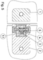
- Fig. 5
- Vertikaler Schnitt in Neutralstellung (Heberkurve bzw. Tür unten), und
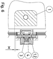
- Fig.6
- Vertikaler Schnitt in geöffneter Stellung (Heberkurve bzw. Tür angehoben).
- In der
Figur 1 sind alle Teile des Scharniers S dargestellt. Weiter werden zumindest angedeutet dargestellt der Türflügel 18 mit Pendelöffnung und ein Festfeld 16 (oder ein Wandabschnitt. - In der
Fig. 2 sind die Tür in 180°- Neutralstellung im horizontalen Schnitt der Dämpfer 3, der Kraftverteiler 4, der Scharnierbolzen 5 mit den Führungsnuten und der der Mitnehmer 6 zu sehen. Der Mitnehmer 6 ist mit mindestens einem Führungssteg 6.1 versehen. Diese Führungsstege 6.1 schaffen die verdrehsichere Verbindung zum Bolzen 5 mit den Führungsnuten 5.2n (min. eine Nut), so dass der Mitnehmer 6 nur noch linear auf dem Bolzen 5 gleitet. - Der Scharnierbolzen 5 ist über die Formschlussflächen 5.1 mit dem Bolzenlager 7 mit der Heberkurve 7.1 über die Formschlussaufnahme 7.2 (nicht sichtbar) und dem Bolzenlager 8 (unten) mit dem Formschluss 8.1 verbunden. Das Bolzenlager 7 mit der Heberkurve 7.2 und das Bolzenlager 8 (unten) sind ebenfalls formschlüssig mit dem Beschlagsteil Tür 2 verbunden. Hierdurch dreht sich der Scharnierbolzen 5 mit der Tür 18. Der Mitnehmer 6 dreht sich mit dem Scharnierbolzen 5 bzw. dem Beschlagsteil Tür 2.
- In der
Fig.3 ist die Tür 18 nach außen geöffnet. Beim Bewegen des Türbeschlags 2 der Tür 18 nach innen oder außen schlägt der auf der Drehachse des Scharnierbolzens 5 linear geführte Mitnehmer 6 an einem Kraftverteiler 4 an. Durch den Druck des Anschlages 6.1 am Mitnehmer 6 auf den Kraftverteiler-4 wird der Dämpfer 3 verdrückt und nimmt die Öffnungskräfte der Tür 18 zum Großteil auf. - Durch die Lineare Führung des Mitnehmers 6 auf dem Scharnierbolzen 5 kann dieser den kompletten zur Verfügung stehenden Platz zwischen dem Drehlager 1 und Drehlager 2 einnehmen. Durch die Lineare Führung des Mitnehmers 6 nimmt dieser die Auf-und Ab-Bewegungen des Hebe-Senk-Mechanismus mit auf. Mitnehmer und Kraftverteiler sind hierdurch ähnlich groß und immer auf gleicher Höhe. Somit erfolgt eine optimale, gleichmäßige Übertragung der Anschlagskräfte auf den Kraftverteiler 4 bzw. Dämpfer 3.
- Die Gläser der Flächen 16 und 18 sind an den Beschlägen 1 und 2 vorzugsweise verklebt und/oder verschraubt.
- Beim Bewegen der Tür 18 nach innen (
Fig. 4 ) passiert das Identische wie beim Öffnen nach außen. - Die Montage erfolgt, wie nachfolgend beschrieben.
- Die Zwischenlagen werden zum Schutz der Glasteile 16, 18 auf die Beschlagsteile 1, 2 aufgeklebt bzw. aufgesteckt. Der Kraftverteiler 4 wird mit dem Dämpfer 3 verbunden und in dafür vorgesehene Öffnung der Hülse 1.1 im Beschlagsteil 1 des Festfeldes bzw. im Beschlagsteil Wand gesteckt. Die Lagerbuchsen 9, 10 werden dann in dafür vorgesehene Öffnung der Hülse 1.1 im Beschlagsteil 1 Festfeld bzw. Beschlagsteil Wand gesteckt. Der Mitnehmer 6 wird zwischen die beiden Lagerbuchsen bzw. Drehlagern 9, 10 geschoben. Danach werden die Dämpfungsabdeckungen 11, 12 montiert. Die komplette Baugruppe wird in der dafür vorgesehenen "Öffnung des Beschlagsteils 2 Tür" montiert. Die beiden Beschlagsteile 1, 2 werden über den Scharnierbolzen 5 mit den Formschlußflächen 5.1 mit den linearen Führungsnuten 5.2 verbunden. Das Bolzenlager 7 mit der Heberkurve 7.2 und das Bolzenlager 8 unten werden formschlüssig in die dafür vorgesehenen Öffnungen des Beschlagsteils 2 Tür gesteckt und mit den vorgesehenen Schrauben 13 mit den jeweiligen Bolzenenden verbunden. Durch die Formschlußflächen 7.1, 8.1 an den Bolzenenden ist der Scharnierbolzen 5 verdrehfest mit dem Türbeschlag 2 verbunden. Dann wird der Glasschutz 17 aufgesteckt und in dafür vorgesehene Öffnung 18.1 im Türglas montiert und mit dem Befestigungsmaterial 19 Tür und Beschlag verbunden. Abschließend werden die Abdeckungen montiert und das Beschlagsteil 1 Festfeld bzw. Beschlagsteil Wand mit dem Festfeld oder der Wand verbinden.
-
- 1 Beschlagsteil Festfeld oder Beschlagsteil Wand mit Hülse1.1 und mit Heberkurve 1.2,
- 2 Beschlagsteile Tür
- 3 Dämpfer
- 4 Kraftverteiler
- 5 Drehbolzen mit Formschlussflächen 5.1 und mit linearen Führungsnuten 5.2, 5.2n
- 6 Mitnehmer mit Steg bzw. Anschlag 6.1 (6.1') und Führungssteg 6.2, 6.2n
- 7 Bolzenlager oben, mit Formschlussaufnahme 7.1 und Heberkurve 7.2
- 8 Bolzenlager unten, mit Formschlussaufnahme 8.1
- 9 Drehlager 1
- 10 Drehlager 2
- 11 Dämpfungsabdeckung
- 12 Unterer Abschluss der Dämpfungsabdeckung
- 13 Schrauben
- 14 Abdeckung Innen
- 15 Achsabdeckungen
- 16 Glas Festfeld oder Wand
- 17 Glasschutz Glas Tür
- 18 Glas Tür mit Pendelöffnung 18.1
- 19 Befestigungsmaterial
- X Hebe- und Senkmechanismus
- S Scharnier
Claims (9)
- Scharnier zur schwenkbaren Halterung eines im wesentlichen ebenen Abschnitts, insbesondere eines Türflügels einer Duschabtrennung an einem Gebäudeabschnitt oder einem Trennwandabschnitt einer Duschabtrennung oder dergleichen, wobei das Scharnier ein erstes Scharnierband (1) mit einer Hülse (1.1) für den Gebäudeabschnitt oder dem anderen Trennwandabschnitt und einen ein zweites Scharnierband (2) für den Türflügel aufweist und die beiden Scharnierbänder (1, 2) über einen, mit einer aus einem Hebe-Senk-Mechanismus (x) bestehenden Schließmechanik versehenen Scharnierbolzen (5) schwenkbar miteinander verbunden sind, dadurch gekennzeichnet, dass der Scharnierbolzen (5) mit einer Anschlagdämpfung in einer Wirkverbindung steht, wobei die Anschlagdämpfung aus einem Dämpfer (3), einen damit verbundenen Kraftverteiler (4) und einen Mitnehmer (6) gebildet wird, die in der Hülse (1.1) des Scharnierteils (1) angeordnet sind, wobei der Mitnehmer (6) über den Scharnierbolzen (5) linear beweglich und verdrehsicher gelagert ist und der Dämpfer (3) mit dem Kraftverteiler (4) fest im Scharnierteil (1) integriert ist.
- Scharnier nach Anspruch 1, dadurch gekennzeichnet, dass in der Hülse (1.1) des Scharnierteils (1) eine Heberkurve (1.2) angeordnet ist.
- Scharnier nach den Ansprüchen 1 und 2, dadurch gekennzeichnet, dass in der Hülse (1.1) des Scharnierteils (1) eine Aufnahme zur Lagerung des Dämpfers (3) vorgesehen ist und der Dämpfer (3) eine Aufnahme für einen Zapfen (4.1) aufweist der am Kraftverteiler (4) angeordnet ist zur kraftschlüssigen Verbindung von Dämpfer und Kraftverteiler.
- Scharnier nach den Ansprüchen 1 bis 3, dadurch gekennzeichnet, dass der Mitnehmer (6) einen Steg aufweist, der die Anschläge (6.1) bildet und mindestens einen Führungssteg 6.2 aufweist.
- Scharnier nach den Ansprüchen 1 bis 4, dadurch gekennzeichnet, dass Bolzenlager (7, 8) zur formschlüssigen Aufnahme des Scharnierbolzens (5) vorgesehen sind.
- Scharnier nach den Ansprüchen 1 bis 5, dadurch gekennzeichnet, dass der Scharnierbolzen (5) Formschlussflächen (5.1) und Führungsnuten (5.2) aufweist, wobei die Formschlussflächen (5.1) mit Formschlussaufnahmen (7.1, 8.1) der Bolzenlager (7, 8) in einer Wirkverbindung stehen und die Führungsnuten (5.2) mit den Führungsstegen (6.2) des Mitnehmers 6 in einer Wirkverbindung stehen.
- Scharnier nach den Ansprüchen 1 bis 6, dadurch gekennzeichnet, dass Hebe-Senk-Mechanismus (x) durch eine in der Hülse (1.1) im Scharnierband (1) vorgesehene untere Heberkurve (1.2) und durch eine am Bolzenlager (7) angeordnete obere Heberkurve (7.2) die in einem Wirkzusammenhang stehen, gebildet wird.
- Scharnier nach einem der o.g. Ansprüche, dadurch gekennzeichnet, dass die Scharnierbänder (1, 2) kraft -, form- und/oder stoffschlüssig mit dem Türflügel und dem Gebäudeabschnitt oder Trennwandabschnitt verbunden sind.
- Duschabtrennung mit einem Türflügel und mindestens einem Scharnier zur Verbindung des Türflügels mit einem Gebäudeabschnitt oder einem Trennwandabschnitt, dadurch gekennzeichnet, dass das bzw. die Scharniere nach wenigstens einem den o.g. Ansprüchen 1 bis 8 ausgebildet sind und der Türflügel als Pendeltür ausgebildet ist.
Applications Claiming Priority (1)
| Application Number | Priority Date | Filing Date | Title |
|---|---|---|---|
| DE102020207128.4A DE102020207128B3 (de) | 2020-06-08 | 2020-06-08 | Scharnier mit integrierter Anschlagdämpfung |
Publications (3)
| Publication Number | Publication Date |
|---|---|
| EP3922798A1 true EP3922798A1 (de) | 2021-12-15 |
| EP3922798C0 EP3922798C0 (de) | 2024-04-03 |
| EP3922798B1 EP3922798B1 (de) | 2024-04-03 |
Family
ID=75936700
Family Applications (1)
| Application Number | Title | Priority Date | Filing Date |
|---|---|---|---|
| EP21173799.4A Active EP3922798B1 (de) | 2020-06-08 | 2021-05-14 | Tür mit einem scharnier mit integrierter anschlagdämpfung |
Country Status (3)
| Country | Link |
|---|---|
| EP (1) | EP3922798B1 (de) |
| DE (1) | DE102020207128B3 (de) |
| PL (1) | PL3922798T3 (de) |
Cited By (2)
| Publication number | Priority date | Publication date | Assignee | Title |
|---|---|---|---|---|
| IT202200019299A1 (it) * | 2022-09-20 | 2024-03-20 | Gessi Spa | Cerniera |
| EP4517035A1 (de) * | 2023-08-30 | 2025-03-05 | Gang Gwo Industrial Co., Ltd | Scharniermechanismus |
Citations (9)
| Publication number | Priority date | Publication date | Assignee | Title |
|---|---|---|---|---|
| DE2125293A1 (de) | 1971-05-21 | 1972-11-30 | Michalides, Friedet, 5820 Gevelsberg | Türhebe-feststell-und schließscharnier |
| DE9002749U1 (de) | 1990-03-06 | 1990-05-10 | Kermi Gmbh, 94447 Plattling | Selbstschließendes Türscharnier |
| DE4231721C2 (de) | 1992-09-22 | 1996-03-21 | Paul Jean Munch | Trennwand für Dusche mit einer Tragvorrichtung für eine verschwenkbare Türe |
| DE19858709A1 (de) | 1998-12-18 | 2000-06-29 | Kermi Gmbh | Scharnier, insbesondere für Türflügel von Duschabtrennungen |
| DE20116691U1 (de) | 2001-10-14 | 2002-09-05 | Huber, Thomas, 69123 Heidelberg | Beschlag für Duschkabine |
| EP2803799A2 (de) * | 2013-05-17 | 2014-11-19 | KERMI GmbH | Scharnier, insbesondere für Türflügel von Duschabtrennungen |
| ITUA20164327A1 (it) * | 2016-06-13 | 2017-12-13 | Technoglass S R L | Cerniera, in particolare per cabine doccia e porte in cristallo |
| DE202018100721U1 (de) | 2018-02-09 | 2018-02-16 | Kermi Gmbh | Scharnier mit einer Bremsvorrichtung |
| DE202020000400U1 (de) | 2019-10-10 | 2020-02-18 | Schulte Duschkabinenbau Gmbh & Co Kg | Beschlag und Duschabtrennung |
Family Cites Families (6)
| Publication number | Priority date | Publication date | Assignee | Title |
|---|---|---|---|---|
| GB1341709A (en) | 1970-06-19 | 1973-12-25 | Shaw Mfg Ltd | Hinges |
| DE102009034740A1 (de) | 2009-07-24 | 2011-01-27 | Dorma Gmbh + Co. Kg | Drehbar gelagerte Tür mit einem Band |
| EP2687660B1 (de) | 2012-07-19 | 2016-12-21 | TIF GmbH | Scharnier |
| CA2908304A1 (en) | 2013-04-12 | 2014-10-16 | In & Tec S.R.L. | Hinge for rotatably moving a door, in particular a glass door |
| AT518054B1 (de) | 2016-05-31 | 2017-07-15 | Tif Gmbh | Scharnier zur Verschwenkung einer Tür |
| AT521462B1 (de) | 2018-09-21 | 2020-02-15 | Tif Gmbh | Scharnier |
-
2020
- 2020-06-08 DE DE102020207128.4A patent/DE102020207128B3/de active Active
-
2021
- 2021-05-14 PL PL21173799.4T patent/PL3922798T3/pl unknown
- 2021-05-14 EP EP21173799.4A patent/EP3922798B1/de active Active
Patent Citations (9)
| Publication number | Priority date | Publication date | Assignee | Title |
|---|---|---|---|---|
| DE2125293A1 (de) | 1971-05-21 | 1972-11-30 | Michalides, Friedet, 5820 Gevelsberg | Türhebe-feststell-und schließscharnier |
| DE9002749U1 (de) | 1990-03-06 | 1990-05-10 | Kermi Gmbh, 94447 Plattling | Selbstschließendes Türscharnier |
| DE4231721C2 (de) | 1992-09-22 | 1996-03-21 | Paul Jean Munch | Trennwand für Dusche mit einer Tragvorrichtung für eine verschwenkbare Türe |
| DE19858709A1 (de) | 1998-12-18 | 2000-06-29 | Kermi Gmbh | Scharnier, insbesondere für Türflügel von Duschabtrennungen |
| DE20116691U1 (de) | 2001-10-14 | 2002-09-05 | Huber, Thomas, 69123 Heidelberg | Beschlag für Duschkabine |
| EP2803799A2 (de) * | 2013-05-17 | 2014-11-19 | KERMI GmbH | Scharnier, insbesondere für Türflügel von Duschabtrennungen |
| ITUA20164327A1 (it) * | 2016-06-13 | 2017-12-13 | Technoglass S R L | Cerniera, in particolare per cabine doccia e porte in cristallo |
| DE202018100721U1 (de) | 2018-02-09 | 2018-02-16 | Kermi Gmbh | Scharnier mit einer Bremsvorrichtung |
| DE202020000400U1 (de) | 2019-10-10 | 2020-02-18 | Schulte Duschkabinenbau Gmbh & Co Kg | Beschlag und Duschabtrennung |
Cited By (4)
| Publication number | Priority date | Publication date | Assignee | Title |
|---|---|---|---|---|
| IT202200019299A1 (it) * | 2022-09-20 | 2024-03-20 | Gessi Spa | Cerniera |
| WO2024062342A1 (en) * | 2022-09-20 | 2024-03-28 | Gessi S.P.A. | Hinge |
| EP4517035A1 (de) * | 2023-08-30 | 2025-03-05 | Gang Gwo Industrial Co., Ltd | Scharniermechanismus |
| US12326024B2 (en) | 2023-08-30 | 2025-06-10 | Gang Gwo Industrial Co., Ltd. | Hinge mechanism |
Also Published As
| Publication number | Publication date |
|---|---|
| PL3922798T3 (pl) | 2024-09-16 |
| EP3922798C0 (de) | 2024-04-03 |
| EP3922798B1 (de) | 2024-04-03 |
| DE102020207128B3 (de) | 2021-11-25 |
Similar Documents
| Publication | Publication Date | Title |
|---|---|---|
| EP1538293B1 (de) | Kombination einer Dämpfungsvorrichtung mit Scharnieren für Möbelstücke | |
| WO2003093616A1 (de) | Mehrgelenkscharnier | |
| EP0065109B1 (de) | Scharnier | |
| EP3922798B1 (de) | Tür mit einem scharnier mit integrierter anschlagdämpfung | |
| DE102020005851A1 (de) | Beschlag und Duschabtrennung | |
| EP3168398B1 (de) | Verstecktes scharnier für türen, fenster oder ähnliche bauteile | |
| EP2130997A2 (de) | Türband | |
| EP1017920B1 (de) | Beschlag zur drehlagerung eines fenster- oder türflügels | |
| DE20200762U1 (de) | Scharnier für Möbel | |
| EP2754813B1 (de) | Band, insbesondere für Kunststoff-Türen und -Fenster | |
| EP3175068B1 (de) | Beschlaganordnung | |
| AT522445B1 (de) | Türanordnung mit einer Stelleinheit | |
| WO2021119689A1 (de) | Führungsvorrichtung zur führung eines möbelteils | |
| DE202008010012U1 (de) | Klappenhalter für eine Möbelklappe | |
| DE69824122T2 (de) | Scharniervorrichtung, insbesondere für eine Tür eines elektrischen Haushaltsgerätes o.dgl., mit selbstregulierendem Gewichtsausgleich | |
| EP2369111B1 (de) | Zur verdeckten Anordnung vorgesehenes Ecklager | |
| DE19738931C1 (de) | Scharnier für Behälterabdeckungen | |
| DE102008028598B4 (de) | Insektenschutztür | |
| DE202007011982U1 (de) | Verstellbares Band | |
| DE102017104304B3 (de) | Türbeschlagstruktur für eine schwenkbare Tür | |
| EP0931897A1 (de) | Scharnier mit integriertem Feststeller | |
| DE60203732T2 (de) | Gegengewicht-scharnier-vorrichtung mit vertikalbewegung für eine tür | |
| EP2511463B1 (de) | Fenster, Tür oder dergleichen mit einer Dämpfereinrichtung | |
| DE202016001398U1 (de) | Fenster oder Tür | |
| DE969168C (de) | Lager fuer um eine mittlere waagerechte oder lotrechte Achse schwenkbare Fluegel von Fenstern |
Legal Events
| Date | Code | Title | Description |
|---|---|---|---|
| PUAI | Public reference made under article 153(3) epc to a published international application that has entered the european phase |
Free format text: ORIGINAL CODE: 0009012 |
|
| STAA | Information on the status of an ep patent application or granted ep patent |
Free format text: STATUS: THE APPLICATION HAS BEEN PUBLISHED |
|
| AK | Designated contracting states |
Kind code of ref document: A1 Designated state(s): AL AT BE BG CH CY CZ DE DK EE ES FI FR GB GR HR HU IE IS IT LI LT LU LV MC MK MT NL NO PL PT RO RS SE SI SK SM TR |
|
| B565 | Issuance of search results under rule 164(2) epc |
Effective date: 20211026 |
|
| STAA | Information on the status of an ep patent application or granted ep patent |
Free format text: STATUS: REQUEST FOR EXAMINATION WAS MADE |
|
| 17P | Request for examination filed |
Effective date: 20220614 |
|
| RBV | Designated contracting states (corrected) |
Designated state(s): AL AT BE BG CH CY CZ DE DK EE ES FI FR GB GR HR HU IE IS IT LI LT LU LV MC MK MT NL NO PL PT RO RS SE SI SK SM TR |
|
| RIC1 | Information provided on ipc code assigned before grant |
Ipc: E05D 3/02 20060101ALN20231006BHEP Ipc: E05D 15/54 20060101ALN20231006BHEP Ipc: E05F 5/02 20060101ALI20231006BHEP Ipc: E05F 1/06 20060101AFI20231006BHEP |
|
| GRAP | Despatch of communication of intention to grant a patent |
Free format text: ORIGINAL CODE: EPIDOSNIGR1 |
|
| STAA | Information on the status of an ep patent application or granted ep patent |
Free format text: STATUS: GRANT OF PATENT IS INTENDED |
|
| RIC1 | Information provided on ipc code assigned before grant |
Ipc: E05D 3/02 20060101ALN20231027BHEP Ipc: E05D 15/54 20060101ALN20231027BHEP Ipc: E05F 5/02 20060101ALI20231027BHEP Ipc: E05F 1/06 20060101AFI20231027BHEP |
|
| INTG | Intention to grant announced |
Effective date: 20231120 |
|
| GRAS | Grant fee paid |
Free format text: ORIGINAL CODE: EPIDOSNIGR3 |
|
| GRAA | (expected) grant |
Free format text: ORIGINAL CODE: 0009210 |
|
| STAA | Information on the status of an ep patent application or granted ep patent |
Free format text: STATUS: THE PATENT HAS BEEN GRANTED |
|
| AK | Designated contracting states |
Kind code of ref document: B1 Designated state(s): AL AT BE BG CH CY CZ DE DK EE ES FI FR GB GR HR HU IE IS IT LI LT LU LV MC MK MT NL NO PL PT RO RS SE SI SK SM TR |
|
| REG | Reference to a national code |
Ref country code: CH Ref legal event code: EP |
|
| REG | Reference to a national code |
Ref country code: DE Ref legal event code: R096 Ref document number: 502021003162 Country of ref document: DE |
|
| REG | Reference to a national code |
Ref country code: IE Ref legal event code: FG4D Free format text: LANGUAGE OF EP DOCUMENT: GERMAN |
|
| U01 | Request for unitary effect filed |
Effective date: 20240502 |
|
| U07 | Unitary effect registered |
Designated state(s): AT BE BG DE DK EE FI FR IT LT LU LV MT NL PT SE SI Effective date: 20240510 |
|
| U20 | Renewal fee for the european patent with unitary effect paid |
Year of fee payment: 4 Effective date: 20240515 |
|
| PG25 | Lapsed in a contracting state [announced via postgrant information from national office to epo] |
Ref country code: IS Free format text: LAPSE BECAUSE OF FAILURE TO SUBMIT A TRANSLATION OF THE DESCRIPTION OR TO PAY THE FEE WITHIN THE PRESCRIBED TIME-LIMIT Effective date: 20240803 |
|
| PG25 | Lapsed in a contracting state [announced via postgrant information from national office to epo] |
Ref country code: HR Free format text: LAPSE BECAUSE OF FAILURE TO SUBMIT A TRANSLATION OF THE DESCRIPTION OR TO PAY THE FEE WITHIN THE PRESCRIBED TIME-LIMIT Effective date: 20240403 |
|
| PG25 | Lapsed in a contracting state [announced via postgrant information from national office to epo] |
Ref country code: GR Free format text: LAPSE BECAUSE OF FAILURE TO SUBMIT A TRANSLATION OF THE DESCRIPTION OR TO PAY THE FEE WITHIN THE PRESCRIBED TIME-LIMIT Effective date: 20240704 |
|
| PG25 | Lapsed in a contracting state [announced via postgrant information from national office to epo] |
Ref country code: ES Free format text: LAPSE BECAUSE OF FAILURE TO SUBMIT A TRANSLATION OF THE DESCRIPTION OR TO PAY THE FEE WITHIN THE PRESCRIBED TIME-LIMIT Effective date: 20240403 |
|
| PG25 | Lapsed in a contracting state [announced via postgrant information from national office to epo] |
Ref country code: NO Free format text: LAPSE BECAUSE OF FAILURE TO SUBMIT A TRANSLATION OF THE DESCRIPTION OR TO PAY THE FEE WITHIN THE PRESCRIBED TIME-LIMIT Effective date: 20240703 Ref country code: IS Free format text: LAPSE BECAUSE OF FAILURE TO SUBMIT A TRANSLATION OF THE DESCRIPTION OR TO PAY THE FEE WITHIN THE PRESCRIBED TIME-LIMIT Effective date: 20240803 Ref country code: HR Free format text: LAPSE BECAUSE OF FAILURE TO SUBMIT A TRANSLATION OF THE DESCRIPTION OR TO PAY THE FEE WITHIN THE PRESCRIBED TIME-LIMIT Effective date: 20240403 Ref country code: GR Free format text: LAPSE BECAUSE OF FAILURE TO SUBMIT A TRANSLATION OF THE DESCRIPTION OR TO PAY THE FEE WITHIN THE PRESCRIBED TIME-LIMIT Effective date: 20240704 Ref country code: ES Free format text: LAPSE BECAUSE OF FAILURE TO SUBMIT A TRANSLATION OF THE DESCRIPTION OR TO PAY THE FEE WITHIN THE PRESCRIBED TIME-LIMIT Effective date: 20240403 Ref country code: RS Free format text: LAPSE BECAUSE OF FAILURE TO SUBMIT A TRANSLATION OF THE DESCRIPTION OR TO PAY THE FEE WITHIN THE PRESCRIBED TIME-LIMIT Effective date: 20240703 |
|
| REG | Reference to a national code |
Ref country code: DE Ref legal event code: R026 Ref document number: 502021003162 Country of ref document: DE |
|
| PLBI | Opposition filed |
Free format text: ORIGINAL CODE: 0009260 |
|
| PLAX | Notice of opposition and request to file observation + time limit sent |
Free format text: ORIGINAL CODE: EPIDOSNOBS2 |
|
| PG25 | Lapsed in a contracting state [announced via postgrant information from national office to epo] |
Ref country code: RO Free format text: LAPSE BECAUSE OF FAILURE TO SUBMIT A TRANSLATION OF THE DESCRIPTION OR TO PAY THE FEE WITHIN THE PRESCRIBED TIME-LIMIT Effective date: 20240403 Ref country code: SK Free format text: LAPSE BECAUSE OF FAILURE TO SUBMIT A TRANSLATION OF THE DESCRIPTION OR TO PAY THE FEE WITHIN THE PRESCRIBED TIME-LIMIT Effective date: 20240403 |
|
| PG25 | Lapsed in a contracting state [announced via postgrant information from national office to epo] |
Ref country code: SM Free format text: LAPSE BECAUSE OF FAILURE TO SUBMIT A TRANSLATION OF THE DESCRIPTION OR TO PAY THE FEE WITHIN THE PRESCRIBED TIME-LIMIT Effective date: 20240403 |
|
| PG25 | Lapsed in a contracting state [announced via postgrant information from national office to epo] |
Ref country code: SM Free format text: LAPSE BECAUSE OF FAILURE TO SUBMIT A TRANSLATION OF THE DESCRIPTION OR TO PAY THE FEE WITHIN THE PRESCRIBED TIME-LIMIT Effective date: 20240403 Ref country code: SK Free format text: LAPSE BECAUSE OF FAILURE TO SUBMIT A TRANSLATION OF THE DESCRIPTION OR TO PAY THE FEE WITHIN THE PRESCRIBED TIME-LIMIT Effective date: 20240403 Ref country code: RO Free format text: LAPSE BECAUSE OF FAILURE TO SUBMIT A TRANSLATION OF THE DESCRIPTION OR TO PAY THE FEE WITHIN THE PRESCRIBED TIME-LIMIT Effective date: 20240403 Ref country code: MC Free format text: LAPSE BECAUSE OF FAILURE TO SUBMIT A TRANSLATION OF THE DESCRIPTION OR TO PAY THE FEE WITHIN THE PRESCRIBED TIME-LIMIT Effective date: 20240403 |
|
| 26 | Opposition filed |
Opponent name: TIF GMBH Effective date: 20250103 |
|
| PG25 | Lapsed in a contracting state [announced via postgrant information from national office to epo] |
Ref country code: IE Free format text: LAPSE BECAUSE OF NON-PAYMENT OF DUE FEES Effective date: 20240514 |
|
| U20 | Renewal fee for the european patent with unitary effect paid |
Year of fee payment: 5 Effective date: 20250331 |
|
| PLBB | Reply of patent proprietor to notice(s) of opposition received |
Free format text: ORIGINAL CODE: EPIDOSNOBS3 |
|
| RAP2 | Party data changed (patent owner data changed or rights of a patent transferred) |
Owner name: KERMI DUSCHDESIGN GMBH |
|
| U1K | Transfer of rights of the unitary patent after the registration of the unitary effect |
Owner name: KERMI DUSCHDESIGN GMBH; DE |
|
| PGFP | Annual fee paid to national office [announced via postgrant information from national office to epo] |
Ref country code: CH Payment date: 20250601 Year of fee payment: 5 |
|
| PGFP | Annual fee paid to national office [announced via postgrant information from national office to epo] |
Ref country code: CZ Payment date: 20250415 Year of fee payment: 5 |
|
| PG25 | Lapsed in a contracting state [announced via postgrant information from national office to epo] |
Ref country code: CY Free format text: LAPSE BECAUSE OF FAILURE TO SUBMIT A TRANSLATION OF THE DESCRIPTION OR TO PAY THE FEE WITHIN THE PRESCRIBED TIME-LIMIT; INVALID AB INITIO Effective date: 20210514 |
|
| PG25 | Lapsed in a contracting state [announced via postgrant information from national office to epo] |
Ref country code: HU Free format text: LAPSE BECAUSE OF FAILURE TO SUBMIT A TRANSLATION OF THE DESCRIPTION OR TO PAY THE FEE WITHIN THE PRESCRIBED TIME-LIMIT; INVALID AB INITIO Effective date: 20210514 |
|
| PGFP | Annual fee paid to national office [announced via postgrant information from national office to epo] |
Ref country code: PL Payment date: 20250512 Year of fee payment: 5 |
|
| GBPC | Gb: european patent ceased through non-payment of renewal fee |
Effective date: 20250514 |
|
| RAP4 | Party data changed (patent owner data changed or rights of a patent transferred) |
Owner name: KERMI DUSCHDESIGN GMBH |
|
| U1H | Name or address of the proprietor changed after the registration of the unitary effect |
Owner name: KERMI DUSCHDESIGN GMBH; DE |
|
| PG25 | Lapsed in a contracting state [announced via postgrant information from national office to epo] |
Ref country code: GB Free format text: LAPSE BECAUSE OF NON-PAYMENT OF DUE FEES Effective date: 20250514 |