EP3907170B1 - Sprungaufzugssystem und sprungverfahren zur verwendung im bauprozess eines gebäudes - Google Patents
Sprungaufzugssystem und sprungverfahren zur verwendung im bauprozess eines gebäudes Download PDFInfo
- Publication number
- EP3907170B1 EP3907170B1 EP20214902.7A EP20214902A EP3907170B1 EP 3907170 B1 EP3907170 B1 EP 3907170B1 EP 20214902 A EP20214902 A EP 20214902A EP 3907170 B1 EP3907170 B1 EP 3907170B1
- Authority
- EP
- European Patent Office
- Prior art keywords
- jumping
- elevator
- hoistway
- platform
- elevator car
- Prior art date
- Legal status (The legal status is an assumption and is not a legal conclusion. Google has not performed a legal analysis and makes no representation as to the accuracy of the status listed.)
- Active
Links
Images


Classifications
-
- B—PERFORMING OPERATIONS; TRANSPORTING
- B66—HOISTING; LIFTING; HAULING
- B66B—ELEVATORS; ESCALATORS OR MOVING WALKWAYS
- B66B11/00—Main component parts of lifts in, or associated with, buildings or other structures
- B66B11/04—Driving gear ; Details thereof, e.g. seals
-
- B—PERFORMING OPERATIONS; TRANSPORTING
- B66—HOISTING; LIFTING; HAULING
- B66B—ELEVATORS; ESCALATORS OR MOVING WALKWAYS
- B66B19/00—Mining-hoist operation
- B66B19/002—Mining-hoist operation installing or exchanging guide rails
-
- B—PERFORMING OPERATIONS; TRANSPORTING
- B66—HOISTING; LIFTING; HAULING
- B66B—ELEVATORS; ESCALATORS OR MOVING WALKWAYS
- B66B11/00—Main component parts of lifts in, or associated with, buildings or other structures
- B66B11/0035—Arrangement of driving gear, e.g. location or support
- B66B11/004—Arrangement of driving gear, e.g. location or support in the machine room
-
- B—PERFORMING OPERATIONS; TRANSPORTING
- B66—HOISTING; LIFTING; HAULING
- B66B—ELEVATORS; ESCALATORS OR MOVING WALKWAYS
- B66B11/00—Main component parts of lifts in, or associated with, buildings or other structures
- B66B11/0065—Roping
-
- B—PERFORMING OPERATIONS; TRANSPORTING
- B66—HOISTING; LIFTING; HAULING
- B66B—ELEVATORS; ESCALATORS OR MOVING WALKWAYS
- B66B17/00—Hoistway equipment
- B66B17/12—Counterpoises
-
- B—PERFORMING OPERATIONS; TRANSPORTING
- B66—HOISTING; LIFTING; HAULING
- B66B—ELEVATORS; ESCALATORS OR MOVING WALKWAYS
- B66B19/00—Mining-hoist operation
-
- B—PERFORMING OPERATIONS; TRANSPORTING
- B66—HOISTING; LIFTING; HAULING
- B66B—ELEVATORS; ESCALATORS OR MOVING WALKWAYS
- B66B7/00—Other common features of elevators
- B66B7/02—Guideways; Guides
-
- B—PERFORMING OPERATIONS; TRANSPORTING
- B66—HOISTING; LIFTING; HAULING
- B66B—ELEVATORS; ESCALATORS OR MOVING WALKWAYS
- B66B7/00—Other common features of elevators
- B66B7/02—Guideways; Guides
- B66B7/023—Mounting means therefor
-
- B—PERFORMING OPERATIONS; TRANSPORTING
- B66—HOISTING; LIFTING; HAULING
- B66B—ELEVATORS; ESCALATORS OR MOVING WALKWAYS
- B66B9/00—Kinds or types of lifts in, or associated with, buildings or other structures
Definitions
- the invention pertains to the technical field of elevator, and relates to a jumping elevator system and a jumping method used in a construction process of a building.
- a jumping elevator or referred to as jumping lift
- an elevator car of the jumping elevator system traveling up and down in a well-built hoistway (or referred to as a lift shaft) of the building, materials and/or workers can be conveniently conveyed between different landings.
- the height or level of the hoistway also advances gradually, and the traveling height of the elevator car of the jumping elevator system in the hoistway also needs to be increased continuously, generally through a jumping platform.
- Known conventional elevator systems typically use ropes for lifting, and generally require an elevator machine room to be provided to accommodate drives such as tractor to pull the ropes, thereby lifting the elevator car. Therefore, corresponding space is leaved generally in the hoistway (e.g., at the top of the hoistway) of the building to provide the elevator machine rooms.
- an elevator machine room also needs to be provided to contain a tractor and the like.
- the elevator machine room of the jumping elevator system is generally arranged in a hoist, and even the elevator machine room is arranged on a jumping platform and can jump along with the jumping platform.
- WO 2018/099761 A1 discloses a lift system which is arranged in a lift shaft of a building in the construction phase, and grows with the building by means of at least one lifting process, said system comprising a machine platform with a lift drive machine and a lift cage suspended on the machine platform by means of at least one carrier means, said lift cage being able to be raised during the lifting process.
- WO 2015/003965 A1 discloses a technical auxiliary platform for temporary use in an elevator shaft.
- US 2013/248299 A1 discloses a method to manufacture an elevator including an elevator car and a movable supporting platform.
- US 9 388 020 B2 discloses a method and elevator arrangement wherein a roof structure is lifted higher in a hoistway so as to make more room below the roof structure, the roof structure being a movable roof structure, and in that the movable roof structure is lifted in the hoistway taking support for the lift from a second movable support structure mounted in the hoistway above the roof structure.
- US 9 388 020 B2 discloses the preamble of claims 1 and 5.
- a jumping method of a jumping elevator system is provided as recited in claim 1.
- a jumping elevator system for use in a construction process of a building is provided as recited in claim 5.
- a component when it is alleged that a component is "fixed/secured” to another component, it may be directly fixed/secured to another component or may be indirectly fixed/secured to another component through an intermediate component. On the contrary, when it is alleged that a component is "directly fixed/secured” to another component, an intermediate component does not exist.
- the direction corresponding to "up-down direction” corresponds to the direction of the hoist
- the direction corresponding to "left-right direction” or “lateral direction” is a direction approximately directing from a landing toward interior of the hoistway. It is to be understood that these directional terms are relative concepts, which are used to describe and clarify a relative position.
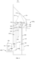
- the pulley assembly can transmit traction from the traction sheave 131 to the elevator car 110 or counterweight 120, which may include a rope 141, one or more top guide sheaves 143, and one or more bottom guide sheaves 144.
- the jumping platform 150 can be implemented in a relatively simple structure and is lightweight, for example, the jumping platform 150 can be implemented in a simple spandrel girder frame or the like and occupies a small hoistway space in the up-down direction; moreover, the jumping platform 150 also thus can be implemented at low cost even though the jumping platform 150 did not be transformed to a component of the conventional elevator system after the building construction is completed, the cost is low for the constructor of the building.
- the jumping platform 150 can be reused in a different jumping elevator system for manufacturers of jumping elevator.
- the lifting assembly in an embodiment includes a hoisting member 171, a hoist 172, a suspension beam 173, and a diverting pulley 174 mounted on the suspension beam 173.
- the lifting assembly may be configured to lift the jumping platform 150 to a higher height when the height of the hoistway 910 is increased, and further lifting the elevator car 110 after lifting the jumping platform 150 so as to extend its traveling distance in the hoistway 910.
- rope compensation may be provided from, for example, the first end 1411 when lifting the elevator car 110, specifically a rope compensating component (not shown in figures) cab be provided at a location corresponding to the first end 1411.
- the jumping platform 150 is lightweight (because the elevator machine room is not provided on the jumping platform 150) and the jumping platform 150 and the elevator car 110 are lifted separately, the lifting power requirement for the lifting assembly is greatly reduced, which favors to simplify the structural design of the lifting assembly and saving the construction cost of a building.
- the lifting assembly prior to lifting the elevator car 110, the lifting assembly is reloaded on the elevator car 110 from the jumping platform 150; specifically, the hoist 172 is removably mounted on the jumping platform 150 or the elevator car 110, and the hoisting member 171 (e.g., a rope) may extend from the hoist 172, wrap though the diverting pulley 174, and extend onto the jumping platform 150 or the elevator car 110; in such, it is easy to reload the hoist 172 and the hoisting member 171 between the jumping platform 150 and the elevator car 110.
- the hoisting member 171 e.g., a rope
- one end of the suspension beam 173 can be hinged and fixed to the landing 920 N , the other end of the suspension beam 173 is in lap joint with the hoistway 910, thereby the dismounting of the lifting assembly relative to the landing 920 is easy, and the workload of the jumping operation is reduced.
- the hoist 172 can be selectively implemented by a cable climber, which is low in cost and small in volume.
- a fixing member e.g., suspension, safety clamp, etc.
- the elevator car 110 can be fixed to the guide rail 930 by the fixing member during lifting of the jumping platform 150, thus free lifting of the jumping platform 150 is unaffected from the elevator car 110.
- the jumping elevator system 10 also includes a temporary working platform 160 used in the jumping process.
- the temporary working platform 160 can be independently arranged relative to the jumping platform 150, and the temporary working platform 160 is provided for preliminarily positioning and mounting the guide rail 930b to be reinforced, jointed at a second height (e.g., the landing 920 N ), relative to the hoistway 910 prior to lifting the jumping platform 150 from the second height (e.g., landing 920 N ); specifically, the temporary working platform 160 is positioned and installed on the landing 920 N+2 and placed in the hoistway 910, thereby providing a worker 90 with a working platform in the hoistway 910; the worker 90 can conveniently mount the guide rail bracket 931b on the wall of the hoistway 910, so that the guide rail 930b to be mounted is primarily positioned and mounted relative to the hoistway 910.
- the temporary working platform 160 is positioned and mounted on a landing 920 (e.g., landing 920 N+2 ) corresponding to a first height by a first uprights 169. After completing the work of preliminary positioning and installing for the guide rail 930b, the temporary working platform 160 can be removed from the landing 920 N+2 and continue to be applied during the next jumping operation.
- the temporary working platform 160 can be realized by a simple steel structure frame, is low in manufacturing cost and can be shared by a plurality of jumping elevator systems 10 in a plurality of hoistways 910, so that the construction cost of a building can be reduced. Also, in conjunction with the following example illustration of the jumping method, it will be appreciated that the temporary working platform 160 will be highly advantageous to avoid the use of scaffolding in the hoistway 910 to position and mount a newly extending rail 930b.
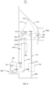
- FIG. 2 shows a structural schematic of a jumping elevator system in accordance with another embodiment of the present invention.
- the jumping elevator system 20 has the main difference lying in that the arrangement of the pulley assembly thereof is different so as to achieve different traction ratio, and the traction ratio of the jumping elevator system 20 is 1: 1.
- the top of the elevator car 110 is not provided with a roof pulley, nor is the top of the counterweight 120 provided with a diverting sheave, and the first end 1411 of the rope 141 is secured to the top of the elevator car 110, the rope 141 extends upwards from the first end 1411 and wraps through the one or more first top guide sheaves 143a, extends downwards and wraps through the first bottom guide sheave 144a, and continues to extend to the traction sheave 131 of the elevator machine room 130; after wrapping through the traction sheave 131, the rope 141 then extends laterally and wraps through one or more second bottom guide sheaves 144b, extends upwards and wraps through a second top guide sheave 143b of the top guide sheave 143, and continues downwards to the counterweight 120. In this way a traction ratio of 1: 1 of the jumping elevator system 20 can be specifically achieved.
- top diverting sheave 145 as shown in FIG. 1 can also be provided on the counterweight 120 in FIG. 2 , through which the rope 141 wraps and extends upwards to the second end 1412, such that an arrangement of the elevator car without a roof pulley and the counterweight with a sheave is achieved.
- pulley assembly arrangements corresponding to other traction ratios may also be applied in the present invention.
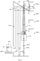
- FIG. 3 shows a flowchart of a method of jumping a jumping elevator system according to an embodiment of the present invention
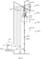
- FIG. 4 to FIG. 9 illustrate a jumping process of the jumping elevator system of the embodiment shown in FIG. 1 based on the jumping method of the embodiment shown in FIG.3
- FIG. 4 illustrates the jumping elevator system preparing for jumping from the landing 920 N
- FIG. 5 illustrates installing the temporary working platform from the landing 920 N+2 for preliminarily positioning and mounting guide rails in the hoistway
- FIG. 6 illustrates the use of the lifting assembly to lift the jumping platform from the landing 920 N to approximately the landing 920 N+2
- FIG. 7 illustrates lifting the elevator car progressively starting from the landing 920 N-1 by use of the lifting assembly and positioning and mounting the guide rails segment by segment on the top of the elevator car
- FIG. 8 illustrates that the elevator car is lifted to the landing 920 N+1 by use of the lifting assembly and all guide rails are positioned and mounted well segment by segment on the top of the elevator car
- FIG. 9 illustrates that the jumping elevator system completes a jumping operation and is ready to regain entering normal elevator operation.
- the operating principle of the jumping elevator system of the embodiment shown in FIG. 1 and an embodiment of jumping method of the invention are illustrated by example below in connection with FIGS. 3-9 .
Landscapes
- Engineering & Computer Science (AREA)
- Structural Engineering (AREA)
- Civil Engineering (AREA)
- Mechanical Engineering (AREA)
- Automation & Control Theory (AREA)
- Lift-Guide Devices, And Elevator Ropes And Cables (AREA)
Claims (15)
- Sprungverfahren eines Sprungaufzugssystems, umfassend:vorläufiges Positionieren und Montieren (S330) einer Führungsschiene (930) auf einem Aufzugsschacht (910), der im Wesentlichen der ersten Höhe entspricht, durch eine temporäre Arbeitsplattform (160) auf einer ersten Höhe;Entfernen (S340) der temporären Arbeitsplattform (160) von der Position des Aufzugsschachts (910), die der ersten Höhe entspricht;Anheben (S350) einer Sprungplattform (150) unter Verwendung einer Hebebaugruppe (171-174) von einer zweiten Höhe auf eine dritte Höhe, wobei die dritte Höhe größer als die zweite Höhe und kleiner oder gleich der ersten Höhe ist; undAnheben (S370) einer Aufzugskabine (110) unter Verwendung der Hebebaugruppe, um ihre Fahrstrecke in dem Aufzugsschacht (910) zu erweitern, wobei das Verfahren gekennzeichnet ist durch:Arbeiten, während des Anhebens der Aufzugskabine (110), auf der Oberseite der Aufzugskabine (110) zum Verstärken der Halterung der Führungsschiene (930); undund Wiederbelasten (S360), vor dem Abheben der Aufzugskabine (110), der Hebebaugruppe an der Aufzugskabine (110) von der Sprungplattform (150).
- Sprungverfahren nach Anspruch 1, ferner umfassend:
Positionieren und Montieren (S320) der temporären Arbeitsplattform (160) auf einem Absatz (920) entsprechend der ersten Höhe durch einen ersten Pfosten vor dem vorläufigen Positionieren und Montieren der Führungsschienen (930). - Sprungverfahren nach Anspruch 1 oder 2, ferner umfassend:Befestigen der Aufzugskabine (110) an der Führungsschiene (930) unterhalb der zweiten Höhe vor dem Anheben der Sprungplattform (150); undLösen der Befestigung der Aufzugskabine (110) relativ zu der Führungsschiene (930) vor dem Anheben der Aufzugskabine (110).
- Sprungverfahren nach Anspruch 1, 2 oder 3, ferner umfassend:Befestigen eines Gegengewichts (120) in dem Aufzugsschacht (910) vor dem Anheben der Sprungplattform (160); undLösen der Befestigung des Gegengewichts (120) nach dem Anheben der Aufzugskabine (110).
- Sprungaufzugssystem (10) zur Verwendung in einem Bauprozess eines Gebäudes, beinhaltend:eine Aufzugskabine (110), die dazu in der Lage ist, in einem Aufzugsschacht (910) des Gebäudes entlang einer Führungsschiene (930) auf- und abzufahren;ein in dem Aufzugsschacht (910) angeordnetes Gegengewicht (120); eine Sprungplattform (160), die in der Lage ist, mit einer Erhöhung der Höhe des Aufzugsschachts (910) mitzuspringen;eine temporäre Arbeitsplattform (150), welche unabhängig relativ zu der Sprungplattform (160) angeordnet ist und zum vorläufigen Positionieren und Montieren der Führungsschiene (930) relativ zu dem Aufzugsschacht (910) vor dem Anheben der Sprungplattform (160) bereitgestellt wird; undeine Hebebaugruppe (171-174) zum Anheben der Sprungplattform (160) auf eine größere Höhe, wenn die Höhe des Aufzugsschachts (910) erhöht wird, wobei die Hebebaugruppe die Aufzugskabine (110) nach dem Anheben der Sprungplattform (160) weiter anhebt, um ihre Fahrstrecke in dem Aufzugsschacht (910) zu erweitern; und gekennzeichnet durch:einen Aufzugsmaschinenraum (130), welcher unabhängig relativ zu der Sprungplattform (160) angeordnet ist und nicht in der Lage ist, mit der Sprungplattform (160) mitzuspringen, wobei der Aufzugsmaschinenraum (130) dazu konfiguriert ist, auf einem Absatz (920) des Gebäudes außerhalb des Aufzugsschachts (910) befestigt zu werden,wobei das Sprungaufzugssystem ferner eine Seilrollenbaugruppe beinhaltet, welche mindestens ein Seil (141), eine obere Führungsscheibe (143a, 143b) und eine untere Führungsscheibe (144a, 144b) umfasst;wobei die obere Führungsscheibe (143a, 143b) auf der Sprungplattform (160) angeordnet ist und in der Lage ist, mit der Sprungplattform (160) mitzuspringen, die obere Führungsscheibe (143a, 143b) und die untere Führungsscheibe (144a, 144b) angeordnet sind, um das Seil (141) so führen, dass es sich mindestens von dem Aufzugsschacht (910) in Richtung einer Treibscheibe (131) in dem Aufzugsmaschinenraum (130) außerhalb des Aufzugsschachts (910) erstreckt.
- Sprungaufzugssystem nach Anspruch 5, wobei die obere Führungsscheibe (143a, 143b) und die untere Führungsscheibe (144a, 144b) ferner angeordnet sind, um das Seil (141) so zu führen, dass es sich mindestens von einer Oberseite der Aufzugskabine (110) in dem Aufzugsschacht (910) in Richtung der Treibscheibe (131) in dem Aufzugsmaschinenraum (130) außerhalb des Aufzugsschachts (910) derart erstreckt, dass eine Zugvorrichtung durch die Seilrollenbaugruppe hindurch eine Zugkraft auf die Oberseite der Aufzugskabine (110) übertragen kann.
- Sprungaufzugssystem nach Anspruch 5 oder 6, wobei die Seilrollenbaugruppe ferner eine Dachseilrolle (142) umfasst, die an der Oberseite der Aufzugskabine (110) bereitgestellt ist; die obere Führungsscheibe (143a, 143b) und die untere Führungsscheibe (144a, 144b) ferner angeordnet sind, um das Seil (141) so zu führen, dass es sich mindestens von der Dachseilrolle (142) in Richtung der Treibscheibe (131) in dem Aufzugsmaschinenraum (130) außerhalb des Aufzugsschachts (910) derart erstreckt, dass eine Zugvorrichtung durch die Seilrollenbaugruppe hindurch eine Zugkraft auf die Oberseite der Aufzugskabine (110) übertragen kann.
- Sprungaufzugssystem nach Anspruch 7, wobei ein erstes Ende des Seils (141) an der Sprungplattform (160) gesichert ist, sich das Seil (141) von dem ersten Ende nach unten erstreckt, die Dachseilrolle (142) umwickelt, sich nach oben erstreckt und eine erste obere Führungsscheibe (143a) der oberen Führungsscheibe umwickelt, sich nach unten erstreckt und eine erste untere Führungsscheibe (144a) der unteren Führungsscheibe umwickelt und sich weiter bis zu der Treibscheibe (131) in dem Aufzugsmaschinenraum (130) erstreckt; sich das Seil (141) nach dem Umwickeln der Treibscheibe (131) dann seitlich erstreckt und eine zweite untere Führungsscheibe (144b) der unterenFührungsscheibe umwickelt, sich nach oben erstreckt und eine zweite obere Führungsscheibe (143b) der oberen Führungsscheibe umwickelt und sich weiter nach unten zu dem Gegengewicht (120) erstreckt.
- Sprungaufzugssystem nach Anspruch 8, wobei die Anzahl der ersten oberen Führungsscheiben (143a, 143b) zwei beträgt und sie seitlich auf der Sprungplattform (160) angeordnet sind, die Anzahl der ersten unteren Führungsscheiben (144a) / der zweiten unteren Führungsscheiben (144b) zwei beträgt und diese im Wesentlichen seitlich angeordnet sind.
- Sprungaufzugssystem nach Anspruch 6, wobei ein erstes Ende des Seils (141) an der Oberseite der Aufzugskabine (110) gesichert ist, sich das Seil (141) von dem ersten Ende nach oben erstreckt, eine erste obere Führungsscheibe (144a) der oberen Führungsscheibe umwickelt, sich nach unten erstreckt und eine erste untere Führungsscheibe (144a) der unteren Führungsscheibe umwickelt und sich weiter bis zu der Treibscheibe (131) in dem Aufzugsmaschinenraum (130) erstreckt; sich das Seil (141) nach dem Umwickeln der Treibscheibe (131) dann seitlich erstreckt und eine zweite untere Führungsscheibe (144b) der unteren Führungsscheibe umwickelt, sich nach oben erstreckt und eine zweite obere Führungsscheibe (143b) der oberen Führungsscheibe umwickelt und sich weiter nach unten zu dem Gegengewicht (120) erstreckt.
- Sprungaufzugssystem nach einem der Ansprüche 5 bis 10, wobei die Sprungplattform (160) einen zweiten Pfosten (159) und ein Schrägseilelement (158) umfasst, wobei der zweite Pfosten (159) relativ zu einem Absatz (920) abnehmbar positioniert und montiert ist, ein Ende der Sprungplattform (160) in der Nähe eines unteren Endes des zweiten Pfostens (159) abnehmbar auf dem Absatz (920) montiert ist und zwei Enden des Schrägseilelements (158) schwenkbar mit dem oberen Ende des zweiten Pfostens (159) bzw. der Sprungplattform (160) verbunden sind.
- Sprungaufzugssystem nach einem der Ansprüche 5 bis 11, wobei ein Befestigungselement entsprechend der Aufzugskabine (110) zum Befestigen der Aufzugskabine (110) an der Führungsschiene (930) während des Anhebens der Sprungplattform (160) bereitgestellt ist.
- Sprungaufzugssystem nach einem der Ansprüche 5 bis 12, wobei die Hebebaugruppe Folgendes umfasst:einen Hängebalken (173);ein Hebezeug (172), das abnehmbar an der Sprungplattform (160) oder der Aufzugskabine (110) installiert ist;eine Umlenkrolle (174), die an dem Hängebalken (173) montiert ist; undein Hebeelement (171), das sich von dem Hebezeug (172) erstreckt, die Umlenkrolle (174) umwickelt und sich auf die Sprungplattform (160) oder die Aufzugskabine (110) erstreckt, wobei das Hebezeug (172) optional ein Seilklettergerät ist.
- Sprungaufzugssystem nach einem der Ansprüche 5 bis 13, wobei die temporäre Arbeitsplattform (150) auf einem entsprechenden Absatz (920) positioniert und montiert ist,
und/oder das Zugverhältnis des Sprungaufzugssystems 2:1 oder 1:1 ist. - Sprungaufzugssystem nach einem der Ansprüche 5 bis 14, wobei während des Anhebens der Aufzugskabine (110) ein Seilausgleich von einem ersten Ende des Seils (141) bereitgestellt wird.
Applications Claiming Priority (1)
| Application Number | Priority Date | Filing Date | Title |
|---|---|---|---|
| CN202010385859.4A CN113620147B (zh) | 2020-05-09 | 2020-05-09 | 在建筑物的建造过程中使用的跃升电梯系统和跃升方法 |
Publications (2)
| Publication Number | Publication Date |
|---|---|
| EP3907170A1 EP3907170A1 (de) | 2021-11-10 |
| EP3907170B1 true EP3907170B1 (de) | 2025-05-07 |
Family
ID=73855271
Family Applications (1)
| Application Number | Title | Priority Date | Filing Date |
|---|---|---|---|
| EP20214902.7A Active EP3907170B1 (de) | 2020-05-09 | 2020-12-17 | Sprungaufzugssystem und sprungverfahren zur verwendung im bauprozess eines gebäudes |
Country Status (4)
| Country | Link |
|---|---|
| US (1) | US11396442B2 (de) |
| EP (1) | EP3907170B1 (de) |
| CN (1) | CN113620147B (de) |
| ES (1) | ES3028786T3 (de) |
Families Citing this family (2)
| Publication number | Priority date | Publication date | Assignee | Title |
|---|---|---|---|---|
| EP4326659A1 (de) * | 2021-04-22 | 2024-02-28 | KONE Corporation | Bauaufzugsanordnung und verfahren zur herstellung davon |
| CN116262586B (zh) * | 2021-12-15 | 2025-12-16 | 上海三菱电梯有限公司 | 跃升电梯及其跃升方法 |
Citations (1)
| Publication number | Priority date | Publication date | Assignee | Title |
|---|---|---|---|---|
| US9388020B2 (en) * | 2012-03-06 | 2016-07-12 | Kone Corporation | Method and an elevator arrangement |
Family Cites Families (56)
| Publication number | Priority date | Publication date | Assignee | Title |
|---|---|---|---|---|
| US3519101A (en) | 1968-01-10 | 1970-07-07 | Otis Elevator Co | Construction elevator system |
| JPS6475384A (en) * | 1987-09-16 | 1989-03-22 | Hitachi Elevator Eng & Service | Method of installation construction of hydraulic elevator |
| JP2862681B2 (ja) | 1991-01-25 | 1999-03-03 | 株式会社東芝 | 本設用品使用の工事用エレベータ据付方法 |
| FR2694279A1 (fr) | 1992-08-03 | 1994-02-04 | Otis Elevator Co | Ascenseur ou monte-charges, suivant l'avancement du gros-Óoeuvre de la construction de bâtiments. |
| JP3193609B2 (ja) * | 1996-01-29 | 2001-07-30 | 株式会社日立ビルシステム | エレベータの据付方法 |
| JPH10316331A (ja) | 1997-05-20 | 1998-12-02 | Shimizu Corp | クライミングエレベータ |
| FR2782072B1 (fr) | 1998-08-06 | 2000-09-22 | Otis Elevator Co | Dispositif et procede pour le deplacement d'une machinerie le long d'une gaine d'ascenseur au cours de la construction d'un immeuble |
| FI108431B (fi) | 1999-02-24 | 2002-01-31 | Kone Corp | Hissijõrjestelmõ |
| JP2001247268A (ja) * | 2000-03-06 | 2001-09-11 | Hitachi Building Systems Co Ltd | ロープ式エレベータ |
| FI114458B (fi) | 2002-12-02 | 2004-10-29 | Kone Corp | Menetelmä ja laitteisto hissin asentamiseksi rakennuksen rakentamisvaiheessa |
| DE502005001056D1 (de) | 2005-04-01 | 2007-08-30 | Knuerr Ag | Lagerungs-Anordnung |
| SG132591A1 (en) | 2005-11-09 | 2007-06-28 | Inventio Ag | Method of constructing a lift installation, and lift installation for that purpose |
| FI118644B (fi) * | 2006-11-17 | 2008-01-31 | Kone Corp | Menetelmä ja laitteisto konehuoneettoman hissin asentamiseksi rakennuksen rakentamisvaiheessa |
| JP5174354B2 (ja) * | 2006-12-25 | 2013-04-03 | パナソニック ホームエレベーター株式会社 | エレベータ装置におけるガイドレールの配設方法 |
| FI118995B (fi) | 2006-12-27 | 2008-06-13 | Kone Corp | Järjestely hissin nopeudenrajoittimen köyden syöttämisessä |
| US20080308362A1 (en) | 2007-06-05 | 2008-12-18 | Stefan Ernest Tucker | Cable management assembly and method for construction elevator systems |
| FI20070694A0 (fi) | 2007-09-11 | 2007-09-11 | Kone Corp | Hissijärjestely |
| WO2009044481A1 (ja) * | 2007-10-05 | 2009-04-09 | Mitsubishi Electric Corporation | エレベータの揚重装置及びエレベータのかご枠及びエレベータの揚重方法 |
| US8291568B2 (en) | 2008-11-28 | 2012-10-23 | Kone Corporation | Method of installing an elevator |
| EP2221269A1 (de) | 2009-02-20 | 2010-08-25 | Inventio AG | Aufzugsanlage mit einem Mehrdeckfahrzeug |
| FI20090085A7 (fi) | 2009-03-06 | 2010-09-30 | Kone Corp | Hissijärjestely ja menetelmä |
| FI20090134L (fi) | 2009-04-06 | 2010-10-07 | Kone Corp | Hissijärjestely ja menetelmä |
| FI121666B (fi) * | 2009-05-28 | 2011-02-28 | Kone Corp | Menetelmä hissin nostoköysistön asentamiseksi |
| JP5278966B2 (ja) | 2009-08-21 | 2013-09-04 | 独立行政法人産業技術総合研究所 | 光信号処理方法及び光信号処理装置 |
| FI20090389L (fi) * | 2009-10-23 | 2011-04-24 | Kone Corp | Menetelmä hissin valmistamisessa |
| FI122066B (fi) * | 2009-12-31 | 2011-08-15 | Kone Corp | Menetelmä hissin valmistamisessa |
| FI20100223A0 (fi) | 2010-05-28 | 2010-05-28 | Kone Corp | Menetelmä ja hissijärjestely |
| FI20106273L (fi) | 2010-12-01 | 2012-06-02 | Kone Corp | Hissijärjestely ja menetelmä |
| FI125115B (fi) | 2010-12-31 | 2015-06-15 | Kone Corp | Menetelmä ja hissijärjestely |
| FI20116190A7 (fi) | 2011-11-28 | 2013-05-29 | Kone Corp | Hissijärjestely ja menetelmä |
| FI20125045L (fi) | 2012-01-16 | 2013-07-17 | Kone Corp | Menetelmä ja hissijärjestely |
| EP2636629B1 (de) * | 2012-03-06 | 2015-05-06 | KONE Corporation | Verfahren für eine Aufzuganordnung |
| NL2008623C2 (en) | 2012-04-11 | 2013-10-15 | Reco Special Products B V | A modular lift apparatus and a method for assembling a modular lift apparatus. |
| DE102012111622A1 (de) | 2012-11-29 | 2014-06-05 | Thyssenkrupp Elevator Ag | Aufzuganlage für ein im Bau befindliches Gebäude |
| DE102013006146A1 (de) * | 2013-04-10 | 2014-10-30 | Geda-Dechentreiter Gmbh & Co. Kg | Aufzug |
| WO2015003965A1 (de) * | 2013-07-10 | 2015-01-15 | Inventio Ag | Erweiterung eines schachtbereiches |
| EP3188997A4 (de) * | 2014-09-01 | 2018-04-11 | KONE Corporation | Verfahren und anordnung zur installation eines aufzugs |
| KR20170096150A (ko) | 2014-12-16 | 2017-08-23 | 인벤티오 아게 | 이동가능한 기계실을 가진 엘리베이터 |
| EP3093262B1 (de) | 2015-05-12 | 2018-10-31 | KONE Corporation | Anordnung und verfahren für parallelen transport und zur installation von aufzugsteilen |
| EP3353107A4 (de) | 2015-09-25 | 2019-06-26 | KONE Corporation | Verfahren zur installation eines aufzugs in der konstruktionsphase eines gebäudes |
| US10807833B2 (en) | 2015-12-14 | 2020-10-20 | Inventio Ag | Method for erecting an elevator system, and elevator system which can be adapted to an increasing building height |
| WO2018002243A1 (de) | 2016-06-30 | 2018-01-04 | Inventio Ag | Verfahren zum errichten einer aufzugsanlage mit einer anpassbaren nutzbaren hubhöhe |
| JP6576567B2 (ja) * | 2016-08-18 | 2019-09-18 | 三菱電機株式会社 | エレベータ改修方法およびエレベータガイドレール |
| WO2018091597A1 (de) | 2016-11-16 | 2018-05-24 | Inventio Ag | Verfahren zum errichten einer aufzugsanlage mit einer anpassbaren nutzbaren hubhöhe |
| WO2018099761A1 (de) * | 2016-11-30 | 2018-06-07 | Inventio Ag | Aufzugsanlage und verfahren zum errichten einer aufzugsanlage |
| EP3388379A1 (de) * | 2017-04-10 | 2018-10-17 | KONE Corporation | Aufzugsanordnung und verfahren |
| EP3412618B1 (de) * | 2017-06-09 | 2020-12-30 | KONE Corporation | Verfahren |
| CN110498321B (zh) | 2018-05-17 | 2022-09-27 | 奥的斯电梯公司 | 补偿线束存储装置、跃层电梯及其使用方法 |
| WO2020035930A1 (ja) | 2018-08-16 | 2020-02-20 | 三菱電機株式会社 | 工事用エレベーターの揚程延長方法およびエレベーター用のロープおろし治具 |
| CN112566864B (zh) | 2018-08-16 | 2022-04-15 | 三菱电机株式会社 | 电梯的扬程延长技术的应用方法 |
| CN110844743B (zh) * | 2018-08-21 | 2022-07-12 | 奥的斯电梯公司 | 跃层电梯和跃层方法 |
| JP6750754B2 (ja) | 2018-08-28 | 2020-09-02 | 三菱電機株式会社 | 揚程延長式工事用エレベーター |
| KR102083484B1 (ko) | 2018-09-20 | 2020-03-02 | 현대엘리베이터주식회사 | 점프 엘리베이터의 레일 리프팅 장치 |
| AU2019345881A1 (en) | 2018-09-26 | 2021-03-11 | Inventio Ag | Method for planning and at least partially installing an elevator system in an elevator shaft |
| CN209052240U (zh) | 2018-11-16 | 2019-07-02 | 中建三局集团有限公司 | 一种用于超高层建筑跃层电梯垂直运输的工具 |
| CN209396744U (zh) | 2019-01-18 | 2019-09-17 | 通力电梯有限公司 | 用于跃层电梯的临时机房和跃层电梯 |
-
2020
- 2020-05-09 CN CN202010385859.4A patent/CN113620147B/zh active Active
- 2020-11-13 US US17/098,012 patent/US11396442B2/en active Active
- 2020-12-17 ES ES20214902T patent/ES3028786T3/es active Active
- 2020-12-17 EP EP20214902.7A patent/EP3907170B1/de active Active
Patent Citations (1)
| Publication number | Priority date | Publication date | Assignee | Title |
|---|---|---|---|---|
| US9388020B2 (en) * | 2012-03-06 | 2016-07-12 | Kone Corporation | Method and an elevator arrangement |
Also Published As
| Publication number | Publication date |
|---|---|
| US11396442B2 (en) | 2022-07-26 |
| CN113620147B (zh) | 2024-07-30 |
| US20210347610A1 (en) | 2021-11-11 |
| EP3907170A1 (de) | 2021-11-10 |
| CN113620147A (zh) | 2021-11-09 |
| ES3028786T3 (en) | 2025-06-20 |
Similar Documents
| Publication | Publication Date | Title |
|---|---|---|
| CN110023229B (zh) | 电梯设备和用于建造电梯设备的方法 | |
| CA2002158C (en) | Elevator erection system using pit storage and roof hoist | |
| FI121666B (fi) | Menetelmä hissin nostoköysistön asentamiseksi | |
| CN1236992C (zh) | 电梯结构装置 | |
| EP3907170B1 (de) | Sprungaufzugssystem und sprungverfahren zur verwendung im bauprozess eines gebäudes | |
| US20160332852A1 (en) | Arrangement and a method for transporting material in an elevator shaft | |
| CN112744665A (zh) | 用于电梯绕绳的方法 | |
| JP2007099515A (ja) | エレベータケージの支持手段をエレベータケージおよびエレベータ昇降路に取り付ける方法 | |
| JP6813123B2 (ja) | エレベーターの揚程延長技術の適用方法 | |
| CN118524983A (zh) | 施工升降机装置和方法 | |
| WO2020142001A1 (en) | A moveable platform | |
| US20230322522A1 (en) | Construction arrangement of an elevator and method | |
| JP7819037B2 (ja) | エレベータ巻上機の据付補助装置及び据付方法 | |
| JP3920527B2 (ja) | 工事用エレベータ | |
| CN117957182A (zh) | 用于建造电梯装置的方法和电梯装置 | |
| CN118139806A (zh) | 施工用电梯及施工用电梯的补偿绳的延长方法 | |
| JP7817016B2 (ja) | 工事用エレベータ | |
| JPH05201648A (ja) | エレベータの据付方法 | |
| JPH05262475A (ja) | エレベータの据付工法 | |
| CN116812719A (zh) | 一种施工升降机的使用方法和施工升降机 | |
| CN119059393A (zh) | 电梯的吊舱设置方法及吊舱装置 | |
| HK40110583A (zh) | 施工升降机装置和方法 | |
| HK40045317A (en) | Method for roping an elevator | |
| HK40112075A (zh) | 升降机施工装置和方法 | |
| JP2003146556A (ja) | エレベータの主ロープ交換装置 |
Legal Events
| Date | Code | Title | Description |
|---|---|---|---|
| PUAI | Public reference made under article 153(3) epc to a published international application that has entered the european phase |
Free format text: ORIGINAL CODE: 0009012 |
|
| STAA | Information on the status of an ep patent application or granted ep patent |
Free format text: STATUS: THE APPLICATION HAS BEEN PUBLISHED |
|
| AK | Designated contracting states |
Kind code of ref document: A1 Designated state(s): AL AT BE BG CH CY CZ DE DK EE ES FI FR GB GR HR HU IE IS IT LI LT LU LV MC MK MT NL NO PL PT RO RS SE SI SK SM TR |
|
| B565 | Issuance of search results under rule 164(2) epc |
Effective date: 20210517 |
|
| STAA | Information on the status of an ep patent application or granted ep patent |
Free format text: STATUS: REQUEST FOR EXAMINATION WAS MADE |
|
| 17P | Request for examination filed |
Effective date: 20220223 |
|
| RBV | Designated contracting states (corrected) |
Designated state(s): AL AT BE BG CH CY CZ DE DK EE ES FI FR GB GR HR HU IE IS IT LI LT LU LV MC MK MT NL NO PL PT RO RS SE SI SK SM TR |
|
| STAA | Information on the status of an ep patent application or granted ep patent |
Free format text: STATUS: EXAMINATION IS IN PROGRESS |
|
| 17Q | First examination report despatched |
Effective date: 20230424 |
|
| GRAP | Despatch of communication of intention to grant a patent |
Free format text: ORIGINAL CODE: EPIDOSNIGR1 |
|
| STAA | Information on the status of an ep patent application or granted ep patent |
Free format text: STATUS: GRANT OF PATENT IS INTENDED |
|
| INTG | Intention to grant announced |
Effective date: 20231030 |
|
| RAP3 | Party data changed (applicant data changed or rights of an application transferred) |
Owner name: OTIS ELEVATOR COMPANY |
|
| GRAJ | Information related to disapproval of communication of intention to grant by the applicant or resumption of examination proceedings by the epo deleted |
Free format text: ORIGINAL CODE: EPIDOSDIGR1 |
|
| STAA | Information on the status of an ep patent application or granted ep patent |
Free format text: STATUS: EXAMINATION IS IN PROGRESS |
|
| INTC | Intention to grant announced (deleted) | ||
| GRAP | Despatch of communication of intention to grant a patent |
Free format text: ORIGINAL CODE: EPIDOSNIGR1 |
|
| STAA | Information on the status of an ep patent application or granted ep patent |
Free format text: STATUS: GRANT OF PATENT IS INTENDED |
|
| INTG | Intention to grant announced |
Effective date: 20250130 |
|
| GRAS | Grant fee paid |
Free format text: ORIGINAL CODE: EPIDOSNIGR3 |
|
| GRAA | (expected) grant |
Free format text: ORIGINAL CODE: 0009210 |
|
| STAA | Information on the status of an ep patent application or granted ep patent |
Free format text: STATUS: THE PATENT HAS BEEN GRANTED |
|
| AK | Designated contracting states |
Kind code of ref document: B1 Designated state(s): AL AT BE BG CH CY CZ DE DK EE ES FI FR GB GR HR HU IE IS IT LI LT LU LV MC MK MT NL NO PL PT RO RS SE SI SK SM TR |
|
| REG | Reference to a national code |
Ref country code: GB Ref legal event code: FG4D |
|
| REG | Reference to a national code |
Ref country code: CH Ref legal event code: EP |
|
| REG | Reference to a national code |
Ref country code: DE Ref legal event code: R096 Ref document number: 602020050755 Country of ref document: DE |
|
| REG | Reference to a national code |
Ref country code: IE Ref legal event code: FG4D |
|
| REG | Reference to a national code |
Ref country code: ES Ref legal event code: FG2A Ref document number: 3028786 Country of ref document: ES Kind code of ref document: T3 Effective date: 20250620 |
|
| REG | Reference to a national code |
Ref country code: NL Ref legal event code: MP Effective date: 20250507 |
|
| PG25 | Lapsed in a contracting state [announced via postgrant information from national office to epo] |
Ref country code: PT Free format text: LAPSE BECAUSE OF FAILURE TO SUBMIT A TRANSLATION OF THE DESCRIPTION OR TO PAY THE FEE WITHIN THE PRESCRIBED TIME-LIMIT Effective date: 20250908 Ref country code: FI Free format text: LAPSE BECAUSE OF FAILURE TO SUBMIT A TRANSLATION OF THE DESCRIPTION OR TO PAY THE FEE WITHIN THE PRESCRIBED TIME-LIMIT Effective date: 20250507 |
|
| REG | Reference to a national code |
Ref country code: LT Ref legal event code: MG9D |
|
| PG25 | Lapsed in a contracting state [announced via postgrant information from national office to epo] |
Ref country code: NO Free format text: LAPSE BECAUSE OF FAILURE TO SUBMIT A TRANSLATION OF THE DESCRIPTION OR TO PAY THE FEE WITHIN THE PRESCRIBED TIME-LIMIT Effective date: 20250807 Ref country code: GR Free format text: LAPSE BECAUSE OF FAILURE TO SUBMIT A TRANSLATION OF THE DESCRIPTION OR TO PAY THE FEE WITHIN THE PRESCRIBED TIME-LIMIT Effective date: 20250808 |
|
| PG25 | Lapsed in a contracting state [announced via postgrant information from national office to epo] |
Ref country code: PL Free format text: LAPSE BECAUSE OF FAILURE TO SUBMIT A TRANSLATION OF THE DESCRIPTION OR TO PAY THE FEE WITHIN THE PRESCRIBED TIME-LIMIT Effective date: 20250507 Ref country code: NL Free format text: LAPSE BECAUSE OF FAILURE TO SUBMIT A TRANSLATION OF THE DESCRIPTION OR TO PAY THE FEE WITHIN THE PRESCRIBED TIME-LIMIT Effective date: 20250507 |
|
| REG | Reference to a national code |
Ref country code: AT Ref legal event code: MK05 Ref document number: 1792321 Country of ref document: AT Kind code of ref document: T Effective date: 20250507 |
|
| PG25 | Lapsed in a contracting state [announced via postgrant information from national office to epo] |
Ref country code: BG Free format text: LAPSE BECAUSE OF FAILURE TO SUBMIT A TRANSLATION OF THE DESCRIPTION OR TO PAY THE FEE WITHIN THE PRESCRIBED TIME-LIMIT Effective date: 20250507 |
|
| PG25 | Lapsed in a contracting state [announced via postgrant information from national office to epo] |
Ref country code: HR Free format text: LAPSE BECAUSE OF FAILURE TO SUBMIT A TRANSLATION OF THE DESCRIPTION OR TO PAY THE FEE WITHIN THE PRESCRIBED TIME-LIMIT Effective date: 20250507 |
|
| PG25 | Lapsed in a contracting state [announced via postgrant information from national office to epo] |
Ref country code: AT Free format text: LAPSE BECAUSE OF FAILURE TO SUBMIT A TRANSLATION OF THE DESCRIPTION OR TO PAY THE FEE WITHIN THE PRESCRIBED TIME-LIMIT Effective date: 20250507 |
|
| PG25 | Lapsed in a contracting state [announced via postgrant information from national office to epo] |
Ref country code: RS Free format text: LAPSE BECAUSE OF FAILURE TO SUBMIT A TRANSLATION OF THE DESCRIPTION OR TO PAY THE FEE WITHIN THE PRESCRIBED TIME-LIMIT Effective date: 20250807 |
|
| PG25 | Lapsed in a contracting state [announced via postgrant information from national office to epo] |
Ref country code: IS Free format text: LAPSE BECAUSE OF FAILURE TO SUBMIT A TRANSLATION OF THE DESCRIPTION OR TO PAY THE FEE WITHIN THE PRESCRIBED TIME-LIMIT Effective date: 20250907 |
|
| PG25 | Lapsed in a contracting state [announced via postgrant information from national office to epo] |
Ref country code: LV Free format text: LAPSE BECAUSE OF FAILURE TO SUBMIT A TRANSLATION OF THE DESCRIPTION OR TO PAY THE FEE WITHIN THE PRESCRIBED TIME-LIMIT Effective date: 20250507 |
|
| PGFP | Annual fee paid to national office [announced via postgrant information from national office to epo] |
Ref country code: DE Payment date: 20251126 Year of fee payment: 6 |
|
| PG25 | Lapsed in a contracting state [announced via postgrant information from national office to epo] |
Ref country code: DK Free format text: LAPSE BECAUSE OF FAILURE TO SUBMIT A TRANSLATION OF THE DESCRIPTION OR TO PAY THE FEE WITHIN THE PRESCRIBED TIME-LIMIT Effective date: 20250507 Ref country code: SM Free format text: LAPSE BECAUSE OF FAILURE TO SUBMIT A TRANSLATION OF THE DESCRIPTION OR TO PAY THE FEE WITHIN THE PRESCRIBED TIME-LIMIT Effective date: 20250507 |
|
| PGFP | Annual fee paid to national office [announced via postgrant information from national office to epo] |
Ref country code: FR Payment date: 20251120 Year of fee payment: 6 |
|
| PG25 | Lapsed in a contracting state [announced via postgrant information from national office to epo] |
Ref country code: CZ Free format text: LAPSE BECAUSE OF FAILURE TO SUBMIT A TRANSLATION OF THE DESCRIPTION OR TO PAY THE FEE WITHIN THE PRESCRIBED TIME-LIMIT Effective date: 20250507 |
|
| PG25 | Lapsed in a contracting state [announced via postgrant information from national office to epo] |
Ref country code: EE Free format text: LAPSE BECAUSE OF FAILURE TO SUBMIT A TRANSLATION OF THE DESCRIPTION OR TO PAY THE FEE WITHIN THE PRESCRIBED TIME-LIMIT Effective date: 20250507 |
|
| PG25 | Lapsed in a contracting state [announced via postgrant information from national office to epo] |
Ref country code: SK Free format text: LAPSE BECAUSE OF FAILURE TO SUBMIT A TRANSLATION OF THE DESCRIPTION OR TO PAY THE FEE WITHIN THE PRESCRIBED TIME-LIMIT Effective date: 20250507 Ref country code: RO Free format text: LAPSE BECAUSE OF FAILURE TO SUBMIT A TRANSLATION OF THE DESCRIPTION OR TO PAY THE FEE WITHIN THE PRESCRIBED TIME-LIMIT Effective date: 20250507 |
|
| PG25 | Lapsed in a contracting state [announced via postgrant information from national office to epo] |
Ref country code: IT Free format text: LAPSE BECAUSE OF FAILURE TO SUBMIT A TRANSLATION OF THE DESCRIPTION OR TO PAY THE FEE WITHIN THE PRESCRIBED TIME-LIMIT Effective date: 20250507 |
|
| REG | Reference to a national code |
Ref country code: DE Ref legal event code: R097 Ref document number: 602020050755 Country of ref document: DE |
|
| PLBE | No opposition filed within time limit |
Free format text: ORIGINAL CODE: 0009261 |
|
| STAA | Information on the status of an ep patent application or granted ep patent |
Free format text: STATUS: NO OPPOSITION FILED WITHIN TIME LIMIT |
|
| REG | Reference to a national code |
Ref country code: CH Ref legal event code: L10 Free format text: ST27 STATUS EVENT CODE: U-0-0-L10-L00 (AS PROVIDED BY THE NATIONAL OFFICE) Effective date: 20260318 |
|
| PGFP | Annual fee paid to national office [announced via postgrant information from national office to epo] |
Ref country code: ES Payment date: 20260102 Year of fee payment: 6 |
|
| 26N | No opposition filed |
Effective date: 20260210 |