EP3905644B1 - Network apparatus - Google Patents
Network apparatus Download PDFInfo
- Publication number
- EP3905644B1 EP3905644B1 EP21169624.0A EP21169624A EP3905644B1 EP 3905644 B1 EP3905644 B1 EP 3905644B1 EP 21169624 A EP21169624 A EP 21169624A EP 3905644 B1 EP3905644 B1 EP 3905644B1
- Authority
- EP
- European Patent Office
- Prior art keywords
- command
- stage
- number information
- module
- counter
- Prior art date
- Legal status (The legal status is an assumption and is not a legal conclusion. Google has not performed a legal analysis and makes no representation as to the accuracy of the status listed.)
- Active
Links
Images


Classifications
-
- H—ELECTRICITY
- H04—ELECTRIC COMMUNICATION TECHNIQUE
- H04L—TRANSMISSION OF DIGITAL INFORMATION, e.g. TELEGRAPHIC COMMUNICATION
- H04L67/00—Network arrangements or protocols for supporting network services or applications
- H04L67/01—Protocols
- H04L67/12—Protocols specially adapted for proprietary or special-purpose networking environments, e.g. medical networks, sensor networks, networks in vehicles or remote metering networks
-
- H—ELECTRICITY
- H04—ELECTRIC COMMUNICATION TECHNIQUE
- H04L—TRANSMISSION OF DIGITAL INFORMATION, e.g. TELEGRAPHIC COMMUNICATION
- H04L61/00—Network arrangements, protocols or services for addressing or naming
- H04L61/50—Address allocation
- H04L61/5038—Address allocation for local use, e.g. in LAN or USB networks, or in a controller area network [CAN]
-
- H—ELECTRICITY
- H04—ELECTRIC COMMUNICATION TECHNIQUE
- H04L—TRANSMISSION OF DIGITAL INFORMATION, e.g. TELEGRAPHIC COMMUNICATION
- H04L61/00—Network arrangements, protocols or services for addressing or naming
- H04L61/45—Network directories; Name-to-address mapping
-
- G—PHYSICS
- G06—COMPUTING OR CALCULATING; COUNTING
- G06F—ELECTRIC DIGITAL DATA PROCESSING
- G06F13/00—Interconnection of, or transfer of information or other signals between, memories, input/output devices or central processing units
- G06F13/38—Information transfer, e.g. on bus
- G06F13/42—Bus transfer protocol, e.g. handshake; Synchronisation
- G06F13/4282—Bus transfer protocol, e.g. handshake; Synchronisation on a serial bus, e.g. I2C bus, SPI bus
-
- H—ELECTRICITY
- H04—ELECTRIC COMMUNICATION TECHNIQUE
- H04L—TRANSMISSION OF DIGITAL INFORMATION, e.g. TELEGRAPHIC COMMUNICATION
- H04L61/00—Network arrangements, protocols or services for addressing or naming
- H04L61/50—Address allocation
- H04L61/5092—Address allocation by self-assignment, e.g. picking addresses at random and testing if they are already in use
Definitions
- the present invention relates to a network apparatus, for example, to a technique for automatically setting identification (ID) numbers of multiple module connected to a network apparatus.
- ID identification
- a plurality of measuring machines is desired to be combined to use ( JP 3299488 ).
- a plurality of control units for example, counters
- an upper-level I/F module or host computer is prepared and connected to an upper-level I/F module or host computer.
- connection may be wired connection or radio connection or may be electric connection or communication connection.
- the communication between the host computer and each of the control units is required for the ID number of each of the control units to be appropriately set.
- an upper-level module an I/F module or a host computer.
- US2018227266A1 describes methods and apparatus for enabling discovery of and assigning unique addresses for identical or similar devices assembled in a serial chain of devices in a high-speed communications link.
- US2010185784A1 describes a system comprising a plurality of electronic devices connected to a bus in operational use.
- US2010280786A1 describes a method and system for addressing an integrated circuit within a daisy chain network.
- the present invention is to provide a network apparatus capable of easily automatically setting ID numbers of multiple modules connected to a network.
- a network apparatus is provided according to appended claim 1.
- a control method is provided according to appended claim 5.
- a module is provided according to appended claim 6.
- a module ID number management program is provided according to appended claim 7.
- FIG. 1 shows an example of a measurement system.
- the measurement system includes a plurality of digital indicators 10 (also referred to as digital dial gauges or electric micrometers) to simultaneously measure multiple points.
- digital indicators 10 also referred to as digital dial gauges or electric micrometers
- Each indicator 10 includes a main-body cylindrical part, a spindle provided in such a manner as to be slidable with respect to the main-body cylindrical part, and an encoder that detects the displacement of the spindle.
- Each indicator 10 is connected to a counter (module) 100.
- the counter 100 is a control unit of the indicator 10 and has functions of a detector, a display, a communication device, a simple calculator, and the like.
- the counter (module)100 is also referred to as a relay unit or a data collecting unit, or may be simply referred to as a small terminal device.
- the counters 100 are connected in series.
- the forefront-stage counter 100 is connected to a host computer 20.
- an interface (I/F) module may be connected between the forefront-stage counter 100 and the host computer 20, for example.
- each counter 100 it is required to have assigned a different ID number to each counter 100 and notified the host computer 20 of the ID number of each counter 100.
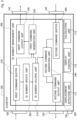
- FIG. 2 is a functional block diagram of each counter 100.
- the counter 100 includes a display 110 and input/output ports 120 to 150 on the outer surface of the housing, and an electric circuit unit inside the housing.
- the electric circuit unit includes a central processing unit (CPU) and a memory (ROM or RAM), and a program (an ID-number management program) stored in the memory executing by the CPU implements functions as the functional units.
- the counter 100 includes, as the input/output ports, a front-stage input port 120, a front-stage output port 130, a rear-stage output port 140, a rear-stage input port 150, and a measuring-machine connection port 160.
- the front-stage input port 120 is connected to its own front-stage counter and receives a signal from its own front-stage counter.
- the front-stage output port 130 is connected to its own front-stage counter and outputs a signal to its own front-stage counter.
- the rear-stage output port 140 is connected to its own rear-stage counter and outputs a signal to its own rear-stage counter.
- the rear-stage input port 150 is connected to its own rear-stage counter and receives a signal from its own rear-stage counter.
- the measuring-machine connection port 160 is used to be connected to the indicator 10.
- One counter 100 may be connected to two or more indicators 10, and the counter 100 may include multiple measuring-machine connection ports 160 in that case.
- front-stage input port 120 and the front-stage output port 130 may not be physically separated, and one front input/output port may function as a front-stage input port and a front-stage output port.
- rear-stage output port 140 and the rear-stage input port 150 may not be physically separated, and one rear input/output port may function as a front-stage input port and a front-stage output port.
- each counter 100 may separately include an upper-level input/output port to be connected to an upper-level module (a host computer or an I/F module).
- an upper-level module a host computer or an I/F module.
- the front-stage input port 120 or the front-stage output port 130 receives or outputs a signal from or to an upper-level module.
- Each counter 100 further includes a displacement detection unit 171, a display control unit 172, a calculation unit 173, and an ID number management unit 200.
- the displacement detection unit 171 detects a scale signal from the scale (encoder) incorporated in the indicator 10 to acquire the displacement of the spindle.
- the display control unit 172 controls display of the display 110 (for example, an LCD panel) and displays, for example, the acquired displacement amount of the spindle on the display 110.
- the calculation unit 173 performs simple calculation, such as origin setting, pre-setting, displaying the maximum and minimum values, range setting, and the like. Then, the counter 100 transmits the detected displacement to the host (the host computer 20), that is, functions as the communication device.
- the ID number management unit 200 exchanges ID number information between the front-stage counter and the rear-stage counter to determine its own ID number.
- the ID number management unit 200 includes an ID number holding unit 210, a first command generation unit 220, a first command output unit 230, a second command generation unit 240, a second command output unit 250, an ID number update unit 260, a first command buffer 270, and a second command buffer 280.
- the ID number holding unit 210 is a memory or a register that holds its own ID number. In order to accept automatic assignment of an ID number, the ID number holding unit 210 is set with a temporary ID number when the power is turned on. In this description, the temporary ID number is assumed to be "01" when the power of the counter 100 is turned on.
- the initial value which is the temporary ID number when the power of the counter 100 is turned on, is rewritten shortly and is not limited as long as the value is any number that does not change.
- the first command generation unit 220 generates a first command signal containing its own ID number held by the ID number holding unit 210 as information. However, if the counter 100 is set with a fixed ID number, the first command signal received from the front-stage counter is directly used as its own first command signal.
- FIG. 3A shows a data format example of the first command signal.
- the first command signal contains, in this order from the head, a header (a start signal), a command type, ID number information on an upper-level module, its own ID number information, and a footer.
- the command type is, for example, a command identification code for identifying this command signal as a first command signal or a second command signal, and a preset command identification code of, for example, A, B, 1, 2, or the like is assigned depending on the type of a signal.
- the ID number information on an upper-level module is used for transferring, when the host computer 20 or the I/F module is included in the system configuration as an upper-level module of the counter 100, the ID number of the host computer 20 or the I/F module to the rear stage. If the first command signal received from a front-stage (or upper-level) module contains the ID number information on the upper-level module, the counter 100 directly transmits that part to the rear stage. In addition, when the counter 100 has received no first command signal from any other modules and is to firstly transmit a first command signal from itself, the counter 100 sets "ID number information on the upper-level module" as, for example, "0".
- the first command output unit 230 outputs the first command signal from the rear-stage output port 140 to its rear-stage counter.
- the second command generation unit 240 generates a second command signal containing its own ID number and ID numbers of its rear-stage modules (counters) as information.
- FIG. 3B shows a data format example of the second command signal.
- the second command signal contains, in this order from the head, a header, a command type, its own ID number and ID numbers of rear-stage counters, and a footer.
- the second command signal is to be concretely described in an operation example described later.
- the second command output unit 250 outputs the second command signal from the front-stage output port 130 to the front-stage counter.
- the ID number update unit 260 When receiving the first command signal from the front-stage counter, the ID number update unit 260 calculates a value by adding "1" to the ID number contained in the first command signal from the front-stage counter. Then, the ID number update unit 260 updates the ID number held by the ID number holding unit 210 to the calculated value as its own new ID number. However, if a fixed ID number has been set, the ID number update unit 260 is not started and in a sleep mode.
- the first command buffer 270 is a memory or a register that temporarily buffers (stores) the first command signal received from the front-stage counter.
- the second command buffer 280 is a memory or a register that temporarily buffers (stores) the second command signal received from the rear-stage counter.
- the counter 100 inputs/outputs the first command signal and the second command signal at predetermined time intervals (for example, 20 ms intervals) until a predetermined time (for example, two seconds) passes from the time when the power is turned on.
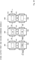
- ID numbers of three counters 100 are automatically set.
- the three counters 100 are referred to as a first counter 400, a second counter 500, and a third counter 600 from the left.
- the first counter 400 is the forefront-stage counter of the three counters and is connected to the host computer 20.
- FIG. 4 the host computer 20 and the indicators 10 are omitted, and only the counters 400, 500, and 600 are shown.
- ID number holding units 410, 510, and 610, first command buffers 470, 570, and 670, and second command buffers 480, 580, and 680 are shown as the functional units of the counters 400, 500, and 600.
- the first counter 400, the second counter 500, and the third counter 600 accept automatic assignment of ID numbers, and a temporary ID number "01" is set in each of the ID number holding units 410, 510, and 610 when the power is turned on.
- each ID number may be displayed on the display 110.
- the temporary ID number "01" is displayed on the display 110 of each of the counters 400, 500, and 600 when the power is turned on, and the number displayed on the display 110 is updated as the ID number is updated in an operation described later.
- the displayed ID number may be blinked or its color may be changed to notify a user that the ID number is not settled, and the settled ID number may be displayed for a predetermined period of time (for example, 5 or 10 seconds) in a normal manner once the ID number is settled.
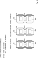
- FIG. 5 is referred to.
- each of the counters 400, 500, and 600 After the power is turned on, each of the counters 400, 500, and 600 outputs a first command signal and a second command signal.
- the first command signal is for notifying the rear-stage counter of its own ID number.
- Each of the counters 400, 500, and 600 outputs the ID number held by each of the respective ID number holding units 410, 510, and 610 as the first command signal.
- each of the counters 400, 500, and 600 has received no first command signal from any other counters, and the ID number has not been updated.
- the first command signal output from each of the counters 400, 500, and 600 is its temporary ID number "01" set as the initial value.
- Each of the counters 400, 500, and 600 outputs the first command signal to its own rear-stage counter.
- the third counter 600 has no rear-stage counter to output the first command signal to.
- the rear-stage output port 140 of the last-stage counter (in this description, the third counter 600) may be attached with a cap to terminate. Alternatively, if a counter has the rear-stage output port 140 attached with an end cap, the counter may output no first command signal.
- the second command signal is for notifying the front-stage counter of its own ID number and the ID numbers of its rear-stage counters.
- the second command generation unit 240 generates the second command signal by adding its own ID number in front of the ID number information stored in the second command buffer 280 (480, 580, and 680).
- each of the counters 400, 500, and 600 has received no second command signal from any other counters.
- the second command signal output from each of the counters 400, 500, and 600 is its temporary ID "01".
- Each of the counters 400, 500, and 600 outputs the second command signal to its own the front-stage counter.
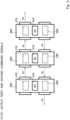
- FIG. 6 is referred to.
- the ID number update unit 260 calculates a value by adding "1" to the ID number contained in the first command signal from the front-stage counter and updates, with the calculated value, the ID number held by the ID number holding unit 210 (410, 510, and 610) as its own new ID number.
- the first counter 400 is the forefront-stage counter and receives no first command signal from the front stage, and its own ID number is not updated and remains as the initial value "01".
- the second counter 500 and the third counter 600 are described.
- Each of the second counter 500 and the third counter 600 has received the first command signal from the front-stage counter in the earlier step ( FIG. 5 ).
- the ID number update unit 260 adds "1" to "01" that is the received first command and overwrites the ID number held by the ID number holding unit 210 (510, 610) to update its own ID number. Then, the ID number of each of the second counter 500 and the third counter 600 becomes "02".
- each of the first counter 400 and the second counter 500 has received the second command signal "01" from the rear-stage counter in the earlier step ( FIG. 5 ).
- the second command buffers 480 and 580 of the first counter 400 and the second counter 500 each store the received second command "01".
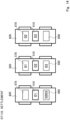
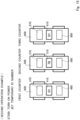
- FIG. 7 is referred to.
- Each of the counters 400, 500, and 600 outputs a first command signal and a second command signal.
- the first command signal is for notifying the rear-stage counter of its own ID number, and each of the counters 400, 500, and 600 outputs the ID number held by each of the ID number holding units 410, 510, and 610 as the first command signal. That is, the first command signal output from the first counter 400 is "01". The first command signal output from each of the second counter 500 and the third counter 600 is "02".
- the second command signal is for notifying the front-stage counter of its own ID number and the ID numbers of its rear-stage counters.
- the second command generation unit 240 generates the second command signal ay adding its own ID number in front of the ID number information stored by each of the second command buffers 480, 580, and 680.
- the third counter 600 is the last-stage counter and receives no second command signal from any other counters, and the second command signal output from the third counter 600 is its own ID number. That is, the second command signal output from the third counter 600 is "02".
- the second counter 500 has received the second command signal "01" from the third counter 600 in the earlier step ( FIG. 5 ) and has stored "01” in the second command buffer 580.
- the second command generation unit 240 of the second counter 500 generates a second command signal "0201” by adding the stored value "01” to follow its own ID number "02" and outputs the generated second command signal from the front-stage output port 130.
- the first counter 400 has received the second command signal "01" from the second counter 500 in the earlier step ( FIG. 5 ) and has stored "01" in the second command buffer 480.
- the second command generation unit 240 of the first counter 400 generates a second command signal "0101" by adding the stored value "01" to follow its own ID number "01” and outputs the generated second command signal to the front stage (the host computer 20).
- FIG. 8 is referred to.
- the third counter 600 has received the first command signal "02" from the second counter 500 in the earlier step ( FIG. 7 ). Thus, its own ID number of the third counter 600 is updated to "03". The ID numbers of the first counter 400 and the second counter 500 eventually remain unchanged although updated, and the explanation for them is omitted.
- the second command buffers 480 and 580 of the first counter 400 and the second counter 500 are described.
- the second command buffer 480 of the first counter 400 stores the second command signal "0201" received from the second counter 500 in the earlier step ( FIG. 7 ).
- the second command buffer 580 of the second counter 500 stores the second command signal "02" received from the third counter 600 in the earlier step ( FIG. 7 ).
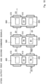
- FIG. 9 is referred to.
- Each of the counters 400, 500, and 600 outputs a first command signal and a second command signal.
- the first command signal is for transferring its own ID number, and the first command signal output from the first counter 400 is "01", the first command signal output from the second counter 500 is "02", and the first command signal output from the third counter 600 is "03".
- the second command signal is generated by adding its own ID number in front of the ID number information on its rear-stage counters stored in each of the second command buffers 480, 580, and 680.
- the second command signal output from the first counter 400 is "010201".
- the second command signal output from the second counter 500 is "0202".
- the second command signal output from the third counter 600 is "03".
- FIG. 10 is referred to.
- Each of the counters 400, 500, and 600 updates its own ID based on the first command signal received in the earlier step ( FIG. 9 ). However, the ID numbers of the first counter 400, the second counter 500, and the third counter 600 have been increased by "1" from the left.
- the ID numbers eventually remain unchanged before and after the ID numbers are updated in this step ( FIG. 10 ).
- the first counter 400 has received the second command signal "0202" from the second counter 500 in the earlier step ( FIG. 9 ), and the second command buffer 480 of the first counter 400 stores "0202".
- the second counter 500 has received the second command signal "03" from the third counter 600 in the earlier step ( FIG. 9 ), and the second command buffer 580 of the second counter 500 stores "03".
- FIG. 11 is referred to.
- Each of the counters 400, 500, and 600 notifies the rear-stage counter of its own ID number information with a first command signal.
- Each ID number has not changed in the earlier step ( FIG. 10 ), and the first command signal output from each of the counters 400, 500, and 600 is the same as that in the step two steps earlier ( FIG. 9 ).
- the second command signal output from each of the counters 400, 500, and 600 is described.
- the second command signal output from the third counter 600 is its own ID number "03" and the same as that in the earlier step ( FIG. 9 ).
- the second counter 500 generates a second command signal "0203" by adding its own ID number "02" in front of "03" that has stored in the second command buffer 580 in the earlier step ( FIG. 10 ).
- the first counter 400 generates a second command signal "010202" by adding its own ID number "01” in front of "0202" that has stored in the second command buffer 480 in the earlier step ( FIG. 10 ).
- FIG. 12 is referred to.
- the ID numbers of the counters 400, 500, and 600 have been already increased by "1" from the left in the earlier step ( FIG. 8 ), and the ID numbers remain unchanged although the counters 400, 500, and 600 update the ID numbers.
- the second command buffers 480, 580, and 680 of the counters 400, 500, and 600 are described.
- the first counter 400 has received the second command signal "0203" from the second counter 500 in the earlier step ( FIG. 11 ), and the second command buffer 480 of the first counter 400 stores "0203".
- the second command buffers 580 and 680 of the second counter 500 and the third counter 600 eventually operate similarly in the earlier step ( FIG. 10 ), and a redundant description is omitted.
- FIG. 13 is referred to.
- Each of the counters 400, 500, and 600 outputs a first command signal and a second command signal.
- the first counter 400 generates a second command signal "010203" by adding its own ID number "01” in front of "0203" stored in the second command buffer 480 in the earlier step ( FIG. 12 ). Then, the host computer 20 is notified of "010203" by the second command signal from the first counter 400.
- the subsequent steps from this step are repetition of FIGS. 12 and 13 , and the counters 400, 500, and 600 continue transmitting the same data (the first command signals and the second command signals) to each other for a predetermined period of time (in this description, two seconds after the power is turned on).
- each of the counters 400, 500, and 600 settles its own ID number as exemplified in FIG. 14 .
- the host computer 20 and the counters 400, 500, and 600 can recognize the ID numbers of their rear-stage counters from the ID number information stored in the second command buffers 480, 580, and 680.
- the present invention it is possible to automatically assign, to the connected multiple counters 100 (400, 500, and 600), ID numbers that are consecutively increased by 1 from that of the forefront-stage counter 400.
- the upper-level host computer 20 it is possible for the upper-level host computer 20 to know the ID numbers of the counters 400, 500, and 600 and for each of the counters 400, 500, and 600 to know, from the on the ID number information stored in the second command buffers 480, 580, and 680 that there are its rear-stage counters and their ID numbers.
- the ID numbers of the counters are automatically appropriately assigned.
- the user is released not only from trouble for manually resetting the ID numbers one by one, but also from mental labor for thinking of assignment of complicated ID numbers.
- FIG. 15 is referred to.
- the first counter 400 is the forefront-stage counter 100 of the three counters 100, and the first counter 400 is connected to the host computer 20 (not shown).
- the ID number of the second counter 500 is assumed to be fixedly set as "78".
- the ID numbers of the first counter 400 and the third counter 600 are to be automatically set.
- FIG. 15 the host computer 20 and the indicator 10 are omitted, and only the counters are shown.
- FIG. 16 is referred to.
- each of the counters 400, 500, and 600 After the power is turned on, each of the counters 400, 500, and 600 outputs a first command signal and a second command signal.
- each of the counters 400, 500, and 600 has received no first command signal from any other counters.
- the ID numbers of the first counter 400 and the third counter 600 are to be automatically set.
- the first command signal firstly output from each of the counters 400 and 600 whose ID numbers are to be automatically set is its temporary ID "01" set as the initial value.
- the ID number of the second counter 500 is fixed.
- the counter When a counter has set with a fixed ID, the counter directly transmits the first command signal received from the front-stage counter to the rear-stage counter as its first command signal, but has received no first command signal from any other counters at the beginning.
- the ID number contained in the first command signal firstly output from the counter (500) whose ID number is fixed is assumed to be "00".
- the first command signal firstly output from the counter whose ID number is fixed may be any ID number that does not change, for example, "01".
- the first command signal firstly output from the counter whose ID number is fixed is preferably the smallest value of ID numbers that are usable in automatic setting or is, as the most suitable example, a value, such as "00", obtained by reducing by one from the minimum ID number "01" that is usable in automatic setting.
- the second command signal is described.
- Each of the counters 400, 500, and 600 has received no second command signal from any other counters, and the second command signal output from each of the counters 400, 500, and 600 is its own ID number. That is, each of the first counter 400 and the third counter 600 outputs its temporary ID number "01" as the second command signal.
- the second counter 500 outputs its own fixed ID number "78" as the second command signal.
- FIG. 17 is referred to.
- the first counter 400 has received no first command signal from the front stage, and its ID number is not updated and remains "01" that is the initial value.
- the ID number of the second counter 500 is "78" that is fixed.
- the third counter 600 has received "00" from the second counter 500 as the first command signal, and updates its own ID number by adding “1" to the received first command "00". As a result, the ID number of the third counter 600 remains "01" and is unchanged.
- the second command buffers 480, 580, and 680 of the counters 400, 500, and 600 are described.
- the first counter 400 stores the second command signal "78" received from the second counter 500 in the second command buffer 480.
- the second counter 500 stores the second command signal "01" received from the third counter 600 in the second command buffer 580.
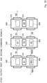
- FIG. 18 is referred to.
- Each of the counters 400, 500, and 600 outputs a first command signal and a second command signal.
- Each of the first counter 400 and the third counter 600 uses its own ID number "01" as the first command signal.
- the second counter 500 has the fixed ID number.
- the second counter 500 directly outputs the first command signal "01" received in the earlier step ( FIG. 16 ) from the front-stage counter (the first counter 400) to the rear-stage counter (the third counter 600). That is, the ID number contained in the first command signal output from the second counter 500 in this step ( FIG. 18 ) is "01".
- a counter whose ID number is fixed may exchange a first command signal similarly to a counter that accepts automatic assignment of an ID number. That is, the counter whose ID number is fixed may start from its temporary ID number "01", update the temporary ID number by adding "1" to the ID number received from the front-stage counter, and transfer its own updated ID number to the rear-stage counter. Then, the counter whose ID number is fixed is only required to eventually use the fixedly set ID number (for example, "78") as its own ID number by discarding the temporary ID number updated automatically. In this case, although the consecutive numbers are broken at the counter whose ID number is fixed, the ID numbers are not overlapped with each other.
- the second command signal is now described.
- the first counter 400 generates a second command signal "0178" by adding its own ID number "01” in front of the second command signal "78" received from the second counter 500 in the earlier step ( FIG. 16 ).
- the second counter 500 generates a second command signal "7801" by adding its own ID number "78" in front of the second command signal "01" received from the third counter 600 in the earlier step ( FIG. 16 ).
- the third counter 600 receives no second command signal from any other counters and uses its own ID number "01" as the second command signal.
- FIG. 19 is referred to.
- the ID numbers of the first counter 400 and the second counter 500 remain unchanged.
- the third counter 600 has received the first command signal "01" from the second counter 500 in the earlier step ( FIG. 18 ) and updates its own ID number to "02" by adding "1" in front of the received first command signal "01".
- the first counter 400 has received the second command signal "7801" from the second counter 500 in the earlier step ( FIG. 18 ) and stores "7801" in the second command buffer 480.
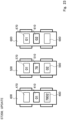
- FIG. 20 is referred to.
- Each of the counters 400, 500, and 600 outputs a first command signal and a second command signal.
- the first command signal output from each of the first counter 400 and the second counter 500 is the same as that in the earlier step ( FIG. 18 ), and a redundant description thereof is omitted.
- the ID number contained in the first command signal output from the third counter 600 is "02" that has been updated. However, the third counter 600 has no rear-stage counter to output the first command signal to.
- the second command signal is now described.
- the first counter 400 generates a second command signal "017801" by adding its own ID number "01” in front of the second command signal "7801" received in the earlier step ( FIG. 18 ).
- the second counter 500 generates a second command signal "7801" by adding its own ID number "78" in front of the second command signal "01" received in the earlier step ( FIG. 18 ).
- the ID number of the third counter 600 has remained unchanged in the earlier steps ( FIGS. 17 and 18 ), and the second command signal output from the second counter 500 in this step ( FIG. 20 ) is eventually the same as that in the earlier step ( FIG. 18 ).
- the third counter 600 outputs its own ID number "02" as the second command signal to the second counter 500.
- FIG. 21 is referred to.
- the ID number of the third counter 600 is "02" in the earlier step ( FIG. 19 ) and is larger by "1" than the ID number of the first counter 400 interposing the second counter 500 whose ID number is fixed therebetween. Thus, the ID numbers of the first counter 400 and the third counter 600 remain unchanged.
- the second counter 500 has received the second command signal "02" from the third counter 600 in the earlier step ( FIG. 20 ) and stores "02" in the second command buffer 580 of the second counter 500.
- the ID numbers stored in the second command buffers 480 and 680 of the first counter 400 and the third counter 600 eventually remain unchanged, and a redundant description thereof is omitted.
- FIG. 22 is referred to.
- Each of the counters 400, 500, and 600 outputs a first command signal and a second command signal.
- the first command signal eventually remains unchanged from that in the earlier step ( FIG. 20 ), and the description thereof is omitted.
- the second counter 500 has received the second command signal "02" from the third counter 600 in the earlier step ( FIG. 20 ) and generates a second command signal "7802" by adding its own ID number "78" in front of the received second command signal.
- the second command signal output from each of the first counter 400 and the third counter 600 is eventually the same as that in the earlier step ( FIG. 20 ), and the description thereof is omitted.
- FIG. 23 is referred to.
- the ID numbers of the first counter 400, the second counter 500, and the third counter 600 remain unchanged.
- the first counter 400 has received the second command signal "7802" from the second counter 500 in the earlier step ( FIG. 22 ), and the second command buffer 480 of the first counter 400 stores "7802".
- the ID number stored in the second command buffer 580 of the second counter 500 eventually remains unchanged, and the description is omitted.
- FIG. 24 is referred to.
- Each of the counters 400, 500, and 600 outputs a first command signal and a second command signal.
- the second command signal of the first counter 400 is changed from that in the earlier step ( FIG. 22 ).
- the first counter 400 has received the second command signal "7802" from the second counter 500 in the earlier step ( FIG. 20 ) and generates a second command signal "017802" by adding its own ID number "01" in front of the received second command signal.
- the subsequent steps from this step are repetition of FIGS. 23 and 24 , and the counters 400, 500, and 600 continue transmitting the same data (the first command signals and the second command signals) for a predetermined period of time (in this description, two seconds after the power is turned on).
- each of the counters 400, 500, and 600 settles its own ID number as exemplified in FIG. 25 .
- the first counter 400 and the third counter 600 set their own ID number "01" and “02” respectively as the automatically set ID numbers.
- the second counter 500 sets the fixedly set ID number "78" as its own ID number.
- the host computer 20 and the counters 400, 500, and 600 can recognize the ID numbers of their own rear-stage counters from the ID number information stored in the second command buffers 480, 580, and 680.
- the present exemplary embodiment although there is a counter whose ID number is fixedly set and the counter does not accept automatic assignment of an ID number, it is possible to automatically assign ID numbers to other counters that accept automatic assignment of ID numbers. At this time, the ID numbers of the counters that accept automatic assignment of ID numbers are to be consecutive in such a manner as to be increased by 1 from the previous one without a missing number.
- the temporary ID number when the power is turned on has been set to a small value "01", and the ID numbers of rear-stage counters have been set (updated) by being sequentially increased (added) by 1 from the ID number of the forefront-stage counter.
- the ID number of the forefront-stage counter may be set to a large number (for example, "49"), and the ID numbers of the rear-stage counters may be set (updated) by being sequentially decreased by "1" from the ID number of the forefront-stage counter.
- ID numbers may be sequentially added or subtracted by “2" as well as being added or subtracted by “1”.
- the functions of the functional units described in the exemplary embodiment may be implemented by arranging a CPU and a memory to function as a computer, installing a predetermined ID number management program in the memory, and executing the installed program by the CPU or the like.
- the ID number management program may be distributed by being recorded in a non-volatile recording medium, such as a CD-ROM, a memory card, or the like, or may be downloaded via an internet network or the like.
Landscapes
- Engineering & Computer Science (AREA)
- Computer Networks & Wireless Communication (AREA)
- Signal Processing (AREA)
- Theoretical Computer Science (AREA)
- Physics & Mathematics (AREA)
- General Physics & Mathematics (AREA)
- General Engineering & Computer Science (AREA)
- Health & Medical Sciences (AREA)
- Computing Systems (AREA)
- General Health & Medical Sciences (AREA)
- Medical Informatics (AREA)
- Small-Scale Networks (AREA)
Applications Claiming Priority (1)
| Application Number | Priority Date | Filing Date | Title |
|---|---|---|---|
| JP2020078000A JP7504654B2 (ja) | 2020-04-27 | 2020-04-27 | ネットワーク装置 |
Publications (2)
| Publication Number | Publication Date |
|---|---|
| EP3905644A1 EP3905644A1 (en) | 2021-11-03 |
| EP3905644B1 true EP3905644B1 (en) | 2023-11-08 |
Family
ID=75625468
Family Applications (1)
| Application Number | Title | Priority Date | Filing Date |
|---|---|---|---|
| EP21169624.0A Active EP3905644B1 (en) | 2020-04-27 | 2021-04-21 | Network apparatus |
Country Status (4)
| Country | Link |
|---|---|
| US (1) | US12267391B2 (https=) |
| EP (1) | EP3905644B1 (https=) |
| JP (1) | JP7504654B2 (https=) |
| CN (1) | CN113645321B (https=) |
Families Citing this family (4)
| Publication number | Priority date | Publication date | Assignee | Title |
|---|---|---|---|---|
| JP1762947S (ja) * | 2023-03-09 | 2024-02-05 | 測長器 | |
| JP1762926S (ja) * | 2023-03-09 | 2024-02-05 | 測長器 | |
| JP1762946S (ja) * | 2023-03-09 | 2024-02-05 | 測長器 | |
| JP1762925S (ja) * | 2023-03-09 | 2024-02-05 | 測長器 |
Family Cites Families (23)
| Publication number | Priority date | Publication date | Assignee | Title |
|---|---|---|---|---|
| JPH0666778B2 (ja) * | 1988-01-27 | 1994-08-24 | 日本電気株式会社 | デジタル加入者線伝送方式 |
| US5321813A (en) * | 1991-05-01 | 1994-06-14 | Teradata Corporation | Reconfigurable, fault tolerant, multistage interconnect network and protocol |
| GB9618131D0 (en) * | 1996-08-30 | 1996-10-09 | Sgs Thomson Microelectronics | Improvements in or relating to an ATM switch |
| JP3299488B2 (ja) | 1997-10-14 | 2002-07-08 | 株式会社ミツトヨ | 測定データの処理装置 |
| JP3791265B2 (ja) * | 1999-11-30 | 2006-06-28 | オムロン株式会社 | 管理局及びノード並びにノードにおける処理方法 |
| US7076636B1 (en) * | 2001-10-05 | 2006-07-11 | Emc Corporation | Data storage system having an improved memory circuit board configured to run scripts |
| JP2003333042A (ja) * | 2002-05-10 | 2003-11-21 | Yaskawa Electric Corp | 自動アドレス割付方法 |
| US7266838B2 (en) * | 2002-10-31 | 2007-09-04 | Hewlett-Packard Development Company, L.P. | Secure resource |
| JP4506222B2 (ja) * | 2004-03-18 | 2010-07-21 | ソニー株式会社 | 通信システム、送信装置および方法、並びにプログラム |
| JP2005277978A (ja) * | 2004-03-26 | 2005-10-06 | Matsushita Electric Ind Co Ltd | 識別番号自動設定方法及び識別番号自動設定装置 |
| US20100185784A1 (en) * | 2007-07-20 | 2010-07-22 | Nxp B.V. | Automatic address assignment for communiation bus |
| EP2425238B1 (en) | 2009-05-01 | 2018-10-17 | Analog Devices, Inc. | An addressable integrated circuit and method thereof |
| CN104202267B (zh) * | 2014-09-19 | 2017-06-23 | 福建星网锐捷网络有限公司 | 网络设备的配置方法及vsd |
| JP6460807B2 (ja) * | 2015-01-22 | 2019-01-30 | 株式会社Fuji | 機器id割り付けシステム |
| US10129203B2 (en) * | 2015-07-09 | 2018-11-13 | International Business Machines Corporation | Network client ID from external managment host via management network |
| WO2017024226A1 (en) * | 2015-08-06 | 2017-02-09 | Intel Corporation | Method and apparatus to enable discovery of identical or similar devices assembled in a serial chain and assign unique addresses to each |
| JP2018064165A (ja) * | 2016-10-12 | 2018-04-19 | アズビル株式会社 | 自動アドレス設定システム |
| CN107094109B (zh) * | 2017-04-26 | 2020-07-07 | 广州睿嵌电子技术有限公司 | 一种车载电子处理单元系统公共网络通讯方法 |
| WO2018235224A1 (ja) * | 2017-06-22 | 2018-12-27 | 株式会社東芝 | ウェブアプリケーションシステム、サーバ装置、端末装置、およびプログラム |
| US10747700B1 (en) * | 2017-12-05 | 2020-08-18 | Amazon Technologies, Inc. | Dynamically configurable pipeline |
| CN109450987B (zh) * | 2018-10-18 | 2021-08-03 | 杭州云永网络科技有限公司 | 编号生成方法、装置及系统和存储介质 |
| JP7227739B2 (ja) | 2018-11-08 | 2023-02-22 | 株式会社日立情報通信エンジニアリング | 通話録音システムおよび通話録音方法 |
| JP7612623B2 (ja) * | 2021-04-09 | 2025-01-14 | 日立ヴァンタラ株式会社 | ストレージシステム及びストレージシステムの制御方法 |
-
2020
- 2020-04-27 JP JP2020078000A patent/JP7504654B2/ja active Active
-
2021
- 2021-04-21 EP EP21169624.0A patent/EP3905644B1/en active Active
- 2021-04-21 US US17/236,061 patent/US12267391B2/en active Active
- 2021-04-26 CN CN202110453235.6A patent/CN113645321B/zh active Active
Also Published As
| Publication number | Publication date |
|---|---|
| EP3905644A1 (en) | 2021-11-03 |
| JP7504654B2 (ja) | 2024-06-24 |
| JP2021175096A (ja) | 2021-11-01 |
| CN113645321A (zh) | 2021-11-12 |
| US20210333079A1 (en) | 2021-10-28 |
| US12267391B2 (en) | 2025-04-01 |
| CN113645321B (zh) | 2024-11-05 |
Similar Documents
| Publication | Publication Date | Title |
|---|---|---|
| EP3905644B1 (en) | Network apparatus | |
| JP3657027B2 (ja) | 車両故障診断装置の時間管理システム及び方法 | |
| US6263380B1 (en) | Measurement data processing unit | |
| EP3376316A1 (en) | Slave device, control method of slave device, information processing program and computer readable recording medium | |
| EP2725436B1 (en) | Communication device connectable to a control device and a plurality of sensors | |
| JP2000234792A (ja) | 空気調和装置の料金管理装置 | |
| US20240194002A1 (en) | Method for Itemizing Mixed Diagnostic Codes | |
| JPH0954567A (ja) | プロセス制御監視システム | |
| US20220155745A1 (en) | Settings information generation device, settings information generation method, and recording medium | |
| KR102103821B1 (ko) | 모드버스 통신 테스트 장치 | |
| US6741071B2 (en) | System and process for exploiting a test | |
| JP3335016B2 (ja) | ワイヤレス式アドレス設定器 | |
| CN113835808A (zh) | 一种显示屏的适配方法、装置、设备及存储介质 | |
| CN120498999B (zh) | 固件升级方法及存储介质 | |
| JP3524466B2 (ja) | データ出力装置および方法 | |
| US20250060722A1 (en) | Control system, programmable logic controller, and recording medium | |
| EP4075735A1 (en) | Data filter, measurement instrument, method | |
| JP7568446B2 (ja) | 情報処理端末、当該情報処理端末を用いた情報処理システムおよび情報処理プログラム | |
| WO1989011119A1 (fr) | Appareil pmc | |
| JP3339556B2 (ja) | 遠隔監視装置の端末装置 | |
| JPH07290547A (ja) | 射出成形機のリモート制御方法及びローカルコントローラ並びにリモート制御装置 | |
| EP3447995A1 (en) | Information processing device, information processing method and program | |
| CN117740167A (zh) | 一种温度显示方法、装置、计算机设备及存储介质 | |
| JP2001201374A (ja) | 測定装置 | |
| JPH10200554A (ja) | データ伝送装置 |
Legal Events
| Date | Code | Title | Description |
|---|---|---|---|
| PUAI | Public reference made under article 153(3) epc to a published international application that has entered the european phase |
Free format text: ORIGINAL CODE: 0009012 |
|
| STAA | Information on the status of an ep patent application or granted ep patent |
Free format text: STATUS: THE APPLICATION HAS BEEN PUBLISHED |
|
| AK | Designated contracting states |
Kind code of ref document: A1 Designated state(s): AL AT BE BG CH CY CZ DE DK EE ES FI FR GB GR HR HU IE IS IT LI LT LU LV MC MK MT NL NO PL PT RO RS SE SI SK SM TR |
|
| B565 | Issuance of search results under rule 164(2) epc |
Effective date: 20210907 |
|
| STAA | Information on the status of an ep patent application or granted ep patent |
Free format text: STATUS: REQUEST FOR EXAMINATION WAS MADE |
|
| 17P | Request for examination filed |
Effective date: 20220422 |
|
| RBV | Designated contracting states (corrected) |
Designated state(s): AL AT BE BG CH CY CZ DE DK EE ES FI FR GB GR HR HU IE IS IT LI LT LU LV MC MK MT NL NO PL PT RO RS SE SI SK SM TR |
|
| STAA | Information on the status of an ep patent application or granted ep patent |
Free format text: STATUS: EXAMINATION IS IN PROGRESS |
|
| 17Q | First examination report despatched |
Effective date: 20220831 |
|
| REG | Reference to a national code |
Ref country code: DE Ref legal event code: R079 Free format text: PREVIOUS MAIN CLASS: H04L0029120000 Ipc: H04L0061503800 Ref document number: 602021006551 Country of ref document: DE |
|
| GRAP | Despatch of communication of intention to grant a patent |
Free format text: ORIGINAL CODE: EPIDOSNIGR1 |
|
| STAA | Information on the status of an ep patent application or granted ep patent |
Free format text: STATUS: GRANT OF PATENT IS INTENDED |
|
| RIC1 | Information provided on ipc code assigned before grant |
Ipc: H04L 61/5038 20220101AFI20230505BHEP |
|
| INTG | Intention to grant announced |
Effective date: 20230605 |
|
| GRAS | Grant fee paid |
Free format text: ORIGINAL CODE: EPIDOSNIGR3 |
|
| GRAA | (expected) grant |
Free format text: ORIGINAL CODE: 0009210 |
|
| STAA | Information on the status of an ep patent application or granted ep patent |
Free format text: STATUS: THE PATENT HAS BEEN GRANTED |
|
| AK | Designated contracting states |
Kind code of ref document: B1 Designated state(s): AL AT BE BG CH CY CZ DE DK EE ES FI FR GB GR HR HU IE IS IT LI LT LU LV MC MK MT NL NO PL PT RO RS SE SI SK SM TR |
|
| REG | Reference to a national code |
Ref country code: GB Ref legal event code: FG4D |
|
| REG | Reference to a national code |
Ref country code: CH Ref legal event code: EP |
|
| REG | Reference to a national code |
Ref country code: DE Ref legal event code: R096 Ref document number: 602021006551 Country of ref document: DE |
|
| REG | Reference to a national code |
Ref country code: IE Ref legal event code: FG4D |
|
| REG | Reference to a national code |
Ref country code: LT Ref legal event code: MG9D |
|
| REG | Reference to a national code |
Ref country code: NL Ref legal event code: MP Effective date: 20231108 |
|
| PG25 | Lapsed in a contracting state [announced via postgrant information from national office to epo] |
Ref country code: GR Free format text: LAPSE BECAUSE OF FAILURE TO SUBMIT A TRANSLATION OF THE DESCRIPTION OR TO PAY THE FEE WITHIN THE PRESCRIBED TIME-LIMIT Effective date: 20240209 |
|
| PG25 | Lapsed in a contracting state [announced via postgrant information from national office to epo] |
Ref country code: IS Free format text: LAPSE BECAUSE OF FAILURE TO SUBMIT A TRANSLATION OF THE DESCRIPTION OR TO PAY THE FEE WITHIN THE PRESCRIBED TIME-LIMIT Effective date: 20240308 |
|
| PG25 | Lapsed in a contracting state [announced via postgrant information from national office to epo] |
Ref country code: LT Free format text: LAPSE BECAUSE OF FAILURE TO SUBMIT A TRANSLATION OF THE DESCRIPTION OR TO PAY THE FEE WITHIN THE PRESCRIBED TIME-LIMIT Effective date: 20231108 |
|
| REG | Reference to a national code |
Ref country code: AT Ref legal event code: MK05 Ref document number: 1630663 Country of ref document: AT Kind code of ref document: T Effective date: 20231108 |
|
| PG25 | Lapsed in a contracting state [announced via postgrant information from national office to epo] |
Ref country code: NL Free format text: LAPSE BECAUSE OF FAILURE TO SUBMIT A TRANSLATION OF THE DESCRIPTION OR TO PAY THE FEE WITHIN THE PRESCRIBED TIME-LIMIT Effective date: 20231108 |
|
| PG25 | Lapsed in a contracting state [announced via postgrant information from national office to epo] |
Ref country code: AT Free format text: LAPSE BECAUSE OF FAILURE TO SUBMIT A TRANSLATION OF THE DESCRIPTION OR TO PAY THE FEE WITHIN THE PRESCRIBED TIME-LIMIT Effective date: 20231108 |
|
| PG25 | Lapsed in a contracting state [announced via postgrant information from national office to epo] |
Ref country code: ES Free format text: LAPSE BECAUSE OF FAILURE TO SUBMIT A TRANSLATION OF THE DESCRIPTION OR TO PAY THE FEE WITHIN THE PRESCRIBED TIME-LIMIT Effective date: 20231108 |
|
| PG25 | Lapsed in a contracting state [announced via postgrant information from national office to epo] |
Ref country code: NL Free format text: LAPSE BECAUSE OF FAILURE TO SUBMIT A TRANSLATION OF THE DESCRIPTION OR TO PAY THE FEE WITHIN THE PRESCRIBED TIME-LIMIT Effective date: 20231108 Ref country code: LT Free format text: LAPSE BECAUSE OF FAILURE TO SUBMIT A TRANSLATION OF THE DESCRIPTION OR TO PAY THE FEE WITHIN THE PRESCRIBED TIME-LIMIT Effective date: 20231108 Ref country code: IS Free format text: LAPSE BECAUSE OF FAILURE TO SUBMIT A TRANSLATION OF THE DESCRIPTION OR TO PAY THE FEE WITHIN THE PRESCRIBED TIME-LIMIT Effective date: 20240308 Ref country code: GR Free format text: LAPSE BECAUSE OF FAILURE TO SUBMIT A TRANSLATION OF THE DESCRIPTION OR TO PAY THE FEE WITHIN THE PRESCRIBED TIME-LIMIT Effective date: 20240209 Ref country code: ES Free format text: LAPSE BECAUSE OF FAILURE TO SUBMIT A TRANSLATION OF THE DESCRIPTION OR TO PAY THE FEE WITHIN THE PRESCRIBED TIME-LIMIT Effective date: 20231108 Ref country code: BG Free format text: LAPSE BECAUSE OF FAILURE TO SUBMIT A TRANSLATION OF THE DESCRIPTION OR TO PAY THE FEE WITHIN THE PRESCRIBED TIME-LIMIT Effective date: 20240208 Ref country code: AT Free format text: LAPSE BECAUSE OF FAILURE TO SUBMIT A TRANSLATION OF THE DESCRIPTION OR TO PAY THE FEE WITHIN THE PRESCRIBED TIME-LIMIT Effective date: 20231108 Ref country code: PT Free format text: LAPSE BECAUSE OF FAILURE TO SUBMIT A TRANSLATION OF THE DESCRIPTION OR TO PAY THE FEE WITHIN THE PRESCRIBED TIME-LIMIT Effective date: 20240308 |
|
| PG25 | Lapsed in a contracting state [announced via postgrant information from national office to epo] |
Ref country code: SE Free format text: LAPSE BECAUSE OF FAILURE TO SUBMIT A TRANSLATION OF THE DESCRIPTION OR TO PAY THE FEE WITHIN THE PRESCRIBED TIME-LIMIT Effective date: 20231108 Ref country code: RS Free format text: LAPSE BECAUSE OF FAILURE TO SUBMIT A TRANSLATION OF THE DESCRIPTION OR TO PAY THE FEE WITHIN THE PRESCRIBED TIME-LIMIT Effective date: 20231108 Ref country code: PL Free format text: LAPSE BECAUSE OF FAILURE TO SUBMIT A TRANSLATION OF THE DESCRIPTION OR TO PAY THE FEE WITHIN THE PRESCRIBED TIME-LIMIT Effective date: 20231108 Ref country code: NO Free format text: LAPSE BECAUSE OF FAILURE TO SUBMIT A TRANSLATION OF THE DESCRIPTION OR TO PAY THE FEE WITHIN THE PRESCRIBED TIME-LIMIT Effective date: 20240208 Ref country code: LV Free format text: LAPSE BECAUSE OF FAILURE TO SUBMIT A TRANSLATION OF THE DESCRIPTION OR TO PAY THE FEE WITHIN THE PRESCRIBED TIME-LIMIT Effective date: 20231108 Ref country code: HR Free format text: LAPSE BECAUSE OF FAILURE TO SUBMIT A TRANSLATION OF THE DESCRIPTION OR TO PAY THE FEE WITHIN THE PRESCRIBED TIME-LIMIT Effective date: 20231108 |
|
| PG25 | Lapsed in a contracting state [announced via postgrant information from national office to epo] |
Ref country code: DK Free format text: LAPSE BECAUSE OF FAILURE TO SUBMIT A TRANSLATION OF THE DESCRIPTION OR TO PAY THE FEE WITHIN THE PRESCRIBED TIME-LIMIT Effective date: 20231108 |
|
| PG25 | Lapsed in a contracting state [announced via postgrant information from national office to epo] |
Ref country code: CZ Free format text: LAPSE BECAUSE OF FAILURE TO SUBMIT A TRANSLATION OF THE DESCRIPTION OR TO PAY THE FEE WITHIN THE PRESCRIBED TIME-LIMIT Effective date: 20231108 |
|
| PG25 | Lapsed in a contracting state [announced via postgrant information from national office to epo] |
Ref country code: SK Free format text: LAPSE BECAUSE OF FAILURE TO SUBMIT A TRANSLATION OF THE DESCRIPTION OR TO PAY THE FEE WITHIN THE PRESCRIBED TIME-LIMIT Effective date: 20231108 |
|
| PG25 | Lapsed in a contracting state [announced via postgrant information from national office to epo] |
Ref country code: SM Free format text: LAPSE BECAUSE OF FAILURE TO SUBMIT A TRANSLATION OF THE DESCRIPTION OR TO PAY THE FEE WITHIN THE PRESCRIBED TIME-LIMIT Effective date: 20231108 Ref country code: SK Free format text: LAPSE BECAUSE OF FAILURE TO SUBMIT A TRANSLATION OF THE DESCRIPTION OR TO PAY THE FEE WITHIN THE PRESCRIBED TIME-LIMIT Effective date: 20231108 Ref country code: RO Free format text: LAPSE BECAUSE OF FAILURE TO SUBMIT A TRANSLATION OF THE DESCRIPTION OR TO PAY THE FEE WITHIN THE PRESCRIBED TIME-LIMIT Effective date: 20231108 Ref country code: IT Free format text: LAPSE BECAUSE OF FAILURE TO SUBMIT A TRANSLATION OF THE DESCRIPTION OR TO PAY THE FEE WITHIN THE PRESCRIBED TIME-LIMIT Effective date: 20231108 Ref country code: EE Free format text: LAPSE BECAUSE OF FAILURE TO SUBMIT A TRANSLATION OF THE DESCRIPTION OR TO PAY THE FEE WITHIN THE PRESCRIBED TIME-LIMIT Effective date: 20231108 Ref country code: DK Free format text: LAPSE BECAUSE OF FAILURE TO SUBMIT A TRANSLATION OF THE DESCRIPTION OR TO PAY THE FEE WITHIN THE PRESCRIBED TIME-LIMIT Effective date: 20231108 Ref country code: CZ Free format text: LAPSE BECAUSE OF FAILURE TO SUBMIT A TRANSLATION OF THE DESCRIPTION OR TO PAY THE FEE WITHIN THE PRESCRIBED TIME-LIMIT Effective date: 20231108 |
|
| REG | Reference to a national code |
Ref country code: DE Ref legal event code: R097 Ref document number: 602021006551 Country of ref document: DE |
|
| PLBE | No opposition filed within time limit |
Free format text: ORIGINAL CODE: 0009261 |
|
| STAA | Information on the status of an ep patent application or granted ep patent |
Free format text: STATUS: NO OPPOSITION FILED WITHIN TIME LIMIT |
|
| 26N | No opposition filed |
Effective date: 20240809 |
|
| PG25 | Lapsed in a contracting state [announced via postgrant information from national office to epo] |
Ref country code: SI Free format text: LAPSE BECAUSE OF FAILURE TO SUBMIT A TRANSLATION OF THE DESCRIPTION OR TO PAY THE FEE WITHIN THE PRESCRIBED TIME-LIMIT Effective date: 20231108 |
|
| PG25 | Lapsed in a contracting state [announced via postgrant information from national office to epo] |
Ref country code: SI Free format text: LAPSE BECAUSE OF FAILURE TO SUBMIT A TRANSLATION OF THE DESCRIPTION OR TO PAY THE FEE WITHIN THE PRESCRIBED TIME-LIMIT Effective date: 20231108 |
|
| PG25 | Lapsed in a contracting state [announced via postgrant information from national office to epo] |
Ref country code: MC Free format text: LAPSE BECAUSE OF FAILURE TO SUBMIT A TRANSLATION OF THE DESCRIPTION OR TO PAY THE FEE WITHIN THE PRESCRIBED TIME-LIMIT Effective date: 20231108 |
|
| PG25 | Lapsed in a contracting state [announced via postgrant information from national office to epo] |
Ref country code: MC Free format text: LAPSE BECAUSE OF FAILURE TO SUBMIT A TRANSLATION OF THE DESCRIPTION OR TO PAY THE FEE WITHIN THE PRESCRIBED TIME-LIMIT Effective date: 20231108 |
|
| REG | Reference to a national code |
Ref country code: CH Ref legal event code: PL |
|
| PG25 | Lapsed in a contracting state [announced via postgrant information from national office to epo] |
Ref country code: LU Free format text: LAPSE BECAUSE OF NON-PAYMENT OF DUE FEES Effective date: 20240421 |
|
| REG | Reference to a national code |
Ref country code: BE Ref legal event code: MM Effective date: 20240430 |
|
| PG25 | Lapsed in a contracting state [announced via postgrant information from national office to epo] |
Ref country code: LU Free format text: LAPSE BECAUSE OF NON-PAYMENT OF DUE FEES Effective date: 20240421 |
|
| PG25 | Lapsed in a contracting state [announced via postgrant information from national office to epo] |
Ref country code: BE Free format text: LAPSE BECAUSE OF NON-PAYMENT OF DUE FEES Effective date: 20240430 |
|
| PG25 | Lapsed in a contracting state [announced via postgrant information from national office to epo] |
Ref country code: FR Free format text: LAPSE BECAUSE OF NON-PAYMENT OF DUE FEES Effective date: 20240430 |
|
| PG25 | Lapsed in a contracting state [announced via postgrant information from national office to epo] |
Ref country code: FR Free format text: LAPSE BECAUSE OF NON-PAYMENT OF DUE FEES Effective date: 20240430 Ref country code: BE Free format text: LAPSE BECAUSE OF NON-PAYMENT OF DUE FEES Effective date: 20240430 Ref country code: CH Free format text: LAPSE BECAUSE OF NON-PAYMENT OF DUE FEES Effective date: 20240430 |
|
| PG25 | Lapsed in a contracting state [announced via postgrant information from national office to epo] |
Ref country code: IE Free format text: LAPSE BECAUSE OF NON-PAYMENT OF DUE FEES Effective date: 20240421 |
|
| PGFP | Annual fee paid to national office [announced via postgrant information from national office to epo] |
Ref country code: DE Payment date: 20250422 Year of fee payment: 5 |
|
| PG25 | Lapsed in a contracting state [announced via postgrant information from national office to epo] |
Ref country code: CY Free format text: LAPSE BECAUSE OF FAILURE TO SUBMIT A TRANSLATION OF THE DESCRIPTION OR TO PAY THE FEE WITHIN THE PRESCRIBED TIME-LIMIT; INVALID AB INITIO Effective date: 20210421 |
|
| PG25 | Lapsed in a contracting state [announced via postgrant information from national office to epo] |
Ref country code: HU Free format text: LAPSE BECAUSE OF FAILURE TO SUBMIT A TRANSLATION OF THE DESCRIPTION OR TO PAY THE FEE WITHIN THE PRESCRIBED TIME-LIMIT; INVALID AB INITIO Effective date: 20210421 |
|
| PG25 | Lapsed in a contracting state [announced via postgrant information from national office to epo] |
Ref country code: FI Free format text: LAPSE BECAUSE OF FAILURE TO SUBMIT A TRANSLATION OF THE DESCRIPTION OR TO PAY THE FEE WITHIN THE PRESCRIBED TIME-LIMIT Effective date: 20231108 |
|
| PGFP | Annual fee paid to national office [announced via postgrant information from national office to epo] |
Ref country code: GB Payment date: 20260306 Year of fee payment: 6 |