EP3903010B1 - Reibungsarme solenoidlagerauskleidung - Google Patents
Reibungsarme solenoidlagerauskleidung Download PDFInfo
- Publication number
- EP3903010B1 EP3903010B1 EP19906198.7A EP19906198A EP3903010B1 EP 3903010 B1 EP3903010 B1 EP 3903010B1 EP 19906198 A EP19906198 A EP 19906198A EP 3903010 B1 EP3903010 B1 EP 3903010B1
- Authority
- EP
- European Patent Office
- Prior art keywords
- layer
- outer layer
- inner layer
- low friction
- bearing liner
- Prior art date
- Legal status (The legal status is an assumption and is not a legal conclusion. Google has not performed a legal analysis and makes no representation as to the accuracy of the status listed.)
- Active
Links
Images


Classifications
-
- F—MECHANICAL ENGINEERING; LIGHTING; HEATING; WEAPONS; BLASTING
- F16—ENGINEERING ELEMENTS AND UNITS; GENERAL MEASURES FOR PRODUCING AND MAINTAINING EFFECTIVE FUNCTIONING OF MACHINES OR INSTALLATIONS; THERMAL INSULATION IN GENERAL
- F16C—SHAFTS; FLEXIBLE SHAFTS; ELEMENTS OR CRANKSHAFT MECHANISMS; ROTARY BODIES OTHER THAN GEARING ELEMENTS; BEARINGS
- F16C33/00—Parts of bearings; Special methods for making bearings or parts thereof
- F16C33/02—Parts of sliding-contact bearings
- F16C33/04—Brasses; Bushes; Linings
- F16C33/06—Sliding surface mainly made of metal
- F16C33/12—Structural composition; Use of special materials or surface treatments, e.g. for rust-proofing
- F16C33/122—Multilayer structures of sleeves, washers or liners
-
- F—MECHANICAL ENGINEERING; LIGHTING; HEATING; WEAPONS; BLASTING
- F16—ENGINEERING ELEMENTS AND UNITS; GENERAL MEASURES FOR PRODUCING AND MAINTAINING EFFECTIVE FUNCTIONING OF MACHINES OR INSTALLATIONS; THERMAL INSULATION IN GENERAL
- F16C—SHAFTS; FLEXIBLE SHAFTS; ELEMENTS OR CRANKSHAFT MECHANISMS; ROTARY BODIES OTHER THAN GEARING ELEMENTS; BEARINGS
- F16C33/00—Parts of bearings; Special methods for making bearings or parts thereof
- F16C33/02—Parts of sliding-contact bearings
- F16C33/04—Brasses; Bushes; Linings
- F16C33/06—Sliding surface mainly made of metal
- F16C33/12—Structural composition; Use of special materials or surface treatments, e.g. for rust-proofing
- F16C33/122—Multilayer structures of sleeves, washers or liners
- F16C33/125—Details of bearing layers, i.e. the lining
-
- F—MECHANICAL ENGINEERING; LIGHTING; HEATING; WEAPONS; BLASTING
- F16—ENGINEERING ELEMENTS AND UNITS; GENERAL MEASURES FOR PRODUCING AND MAINTAINING EFFECTIVE FUNCTIONING OF MACHINES OR INSTALLATIONS; THERMAL INSULATION IN GENERAL
- F16C—SHAFTS; FLEXIBLE SHAFTS; ELEMENTS OR CRANKSHAFT MECHANISMS; ROTARY BODIES OTHER THAN GEARING ELEMENTS; BEARINGS
- F16C17/00—Sliding-contact bearings for exclusively rotary movement
- F16C17/02—Sliding-contact bearings for exclusively rotary movement for radial load only
-
- F—MECHANICAL ENGINEERING; LIGHTING; HEATING; WEAPONS; BLASTING
- F16—ENGINEERING ELEMENTS AND UNITS; GENERAL MEASURES FOR PRODUCING AND MAINTAINING EFFECTIVE FUNCTIONING OF MACHINES OR INSTALLATIONS; THERMAL INSULATION IN GENERAL
- F16C—SHAFTS; FLEXIBLE SHAFTS; ELEMENTS OR CRANKSHAFT MECHANISMS; ROTARY BODIES OTHER THAN GEARING ELEMENTS; BEARINGS
- F16C33/00—Parts of bearings; Special methods for making bearings or parts thereof
- F16C33/02—Parts of sliding-contact bearings
- F16C33/04—Brasses; Bushes; Linings
- F16C33/06—Sliding surface mainly made of metal
- F16C33/12—Structural composition; Use of special materials or surface treatments, e.g. for rust-proofing
- F16C33/121—Use of special materials
-
- F—MECHANICAL ENGINEERING; LIGHTING; HEATING; WEAPONS; BLASTING
- F16—ENGINEERING ELEMENTS AND UNITS; GENERAL MEASURES FOR PRODUCING AND MAINTAINING EFFECTIVE FUNCTIONING OF MACHINES OR INSTALLATIONS; THERMAL INSULATION IN GENERAL
- F16C—SHAFTS; FLEXIBLE SHAFTS; ELEMENTS OR CRANKSHAFT MECHANISMS; ROTARY BODIES OTHER THAN GEARING ELEMENTS; BEARINGS
- F16C33/00—Parts of bearings; Special methods for making bearings or parts thereof
- F16C33/02—Parts of sliding-contact bearings
- F16C33/04—Brasses; Bushes; Linings
- F16C33/20—Sliding surface consisting mainly of plastics
- F16C33/203—Multilayer structures, e.g. sleeves comprising a plastic lining
-
- F—MECHANICAL ENGINEERING; LIGHTING; HEATING; WEAPONS; BLASTING
- F16—ENGINEERING ELEMENTS AND UNITS; GENERAL MEASURES FOR PRODUCING AND MAINTAINING EFFECTIVE FUNCTIONING OF MACHINES OR INSTALLATIONS; THERMAL INSULATION IN GENERAL
- F16C—SHAFTS; FLEXIBLE SHAFTS; ELEMENTS OR CRANKSHAFT MECHANISMS; ROTARY BODIES OTHER THAN GEARING ELEMENTS; BEARINGS
- F16C33/00—Parts of bearings; Special methods for making bearings or parts thereof
- F16C33/02—Parts of sliding-contact bearings
- F16C33/04—Brasses; Bushes; Linings
- F16C33/20—Sliding surface consisting mainly of plastics
- F16C33/203—Multilayer structures, e.g. sleeves comprising a plastic lining
- F16C33/206—Multilayer structures, e.g. sleeves comprising a plastic lining with three layers
-
- H—ELECTRICITY
- H01—ELECTRIC ELEMENTS
- H01F—MAGNETS; INDUCTANCES; TRANSFORMERS; SELECTION OF MATERIALS FOR THEIR MAGNETIC PROPERTIES
- H01F7/00—Magnets
- H01F7/06—Electromagnets; Actuators including electromagnets
- H01F7/08—Electromagnets; Actuators including electromagnets with armatures
- H01F7/081—Magnetic constructions
-
- H—ELECTRICITY
- H01—ELECTRIC ELEMENTS
- H01F—MAGNETS; INDUCTANCES; TRANSFORMERS; SELECTION OF MATERIALS FOR THEIR MAGNETIC PROPERTIES
- H01F7/00—Magnets
- H01F7/06—Electromagnets; Actuators including electromagnets
- H01F7/08—Electromagnets; Actuators including electromagnets with armatures
- H01F7/16—Rectilinearly-movable armatures
-
- F—MECHANICAL ENGINEERING; LIGHTING; HEATING; WEAPONS; BLASTING
- F16—ENGINEERING ELEMENTS AND UNITS; GENERAL MEASURES FOR PRODUCING AND MAINTAINING EFFECTIVE FUNCTIONING OF MACHINES OR INSTALLATIONS; THERMAL INSULATION IN GENERAL
- F16C—SHAFTS; FLEXIBLE SHAFTS; ELEMENTS OR CRANKSHAFT MECHANISMS; ROTARY BODIES OTHER THAN GEARING ELEMENTS; BEARINGS
- F16C2202/00—Solid materials defined by their properties
- F16C2202/02—Mechanical properties
-
- F—MECHANICAL ENGINEERING; LIGHTING; HEATING; WEAPONS; BLASTING
- F16—ENGINEERING ELEMENTS AND UNITS; GENERAL MEASURES FOR PRODUCING AND MAINTAINING EFFECTIVE FUNCTIONING OF MACHINES OR INSTALLATIONS; THERMAL INSULATION IN GENERAL
- F16C—SHAFTS; FLEXIBLE SHAFTS; ELEMENTS OR CRANKSHAFT MECHANISMS; ROTARY BODIES OTHER THAN GEARING ELEMENTS; BEARINGS
- F16C2208/00—Plastics; Synthetic resins, e.g. rubbers
- F16C2208/20—Thermoplastic resins
- F16C2208/30—Fluoropolymers
-
- F—MECHANICAL ENGINEERING; LIGHTING; HEATING; WEAPONS; BLASTING
- F16—ENGINEERING ELEMENTS AND UNITS; GENERAL MEASURES FOR PRODUCING AND MAINTAINING EFFECTIVE FUNCTIONING OF MACHINES OR INSTALLATIONS; THERMAL INSULATION IN GENERAL
- F16C—SHAFTS; FLEXIBLE SHAFTS; ELEMENTS OR CRANKSHAFT MECHANISMS; ROTARY BODIES OTHER THAN GEARING ELEMENTS; BEARINGS
- F16C2208/00—Plastics; Synthetic resins, e.g. rubbers
- F16C2208/20—Thermoplastic resins
- F16C2208/30—Fluoropolymers
- F16C2208/32—Polytetrafluorethylene [PTFE]
-
- F—MECHANICAL ENGINEERING; LIGHTING; HEATING; WEAPONS; BLASTING
- F16—ENGINEERING ELEMENTS AND UNITS; GENERAL MEASURES FOR PRODUCING AND MAINTAINING EFFECTIVE FUNCTIONING OF MACHINES OR INSTALLATIONS; THERMAL INSULATION IN GENERAL
- F16C—SHAFTS; FLEXIBLE SHAFTS; ELEMENTS OR CRANKSHAFT MECHANISMS; ROTARY BODIES OTHER THAN GEARING ELEMENTS; BEARINGS
- F16C2208/00—Plastics; Synthetic resins, e.g. rubbers
- F16C2208/20—Thermoplastic resins
- F16C2208/40—Imides, e.g. polyimide [PI], polyetherimide [PEI]
-
- F—MECHANICAL ENGINEERING; LIGHTING; HEATING; WEAPONS; BLASTING
- F16—ENGINEERING ELEMENTS AND UNITS; GENERAL MEASURES FOR PRODUCING AND MAINTAINING EFFECTIVE FUNCTIONING OF MACHINES OR INSTALLATIONS; THERMAL INSULATION IN GENERAL
- F16C—SHAFTS; FLEXIBLE SHAFTS; ELEMENTS OR CRANKSHAFT MECHANISMS; ROTARY BODIES OTHER THAN GEARING ELEMENTS; BEARINGS
- F16C2208/00—Plastics; Synthetic resins, e.g. rubbers
- F16C2208/20—Thermoplastic resins
- F16C2208/40—Imides, e.g. polyimide [PI], polyetherimide [PEI]
- F16C2208/42—Polyamideimide [PAI]
-
- F—MECHANICAL ENGINEERING; LIGHTING; HEATING; WEAPONS; BLASTING
- F16—ENGINEERING ELEMENTS AND UNITS; GENERAL MEASURES FOR PRODUCING AND MAINTAINING EFFECTIVE FUNCTIONING OF MACHINES OR INSTALLATIONS; THERMAL INSULATION IN GENERAL
- F16C—SHAFTS; FLEXIBLE SHAFTS; ELEMENTS OR CRANKSHAFT MECHANISMS; ROTARY BODIES OTHER THAN GEARING ELEMENTS; BEARINGS
- F16C2208/00—Plastics; Synthetic resins, e.g. rubbers
- F16C2208/20—Thermoplastic resins
- F16C2208/40—Imides, e.g. polyimide [PI], polyetherimide [PEI]
- F16C2208/44—Polybenzimidazole [PBI]
-
- F—MECHANICAL ENGINEERING; LIGHTING; HEATING; WEAPONS; BLASTING
- F16—ENGINEERING ELEMENTS AND UNITS; GENERAL MEASURES FOR PRODUCING AND MAINTAINING EFFECTIVE FUNCTIONING OF MACHINES OR INSTALLATIONS; THERMAL INSULATION IN GENERAL
- F16C—SHAFTS; FLEXIBLE SHAFTS; ELEMENTS OR CRANKSHAFT MECHANISMS; ROTARY BODIES OTHER THAN GEARING ELEMENTS; BEARINGS
- F16C2208/00—Plastics; Synthetic resins, e.g. rubbers
- F16C2208/20—Thermoplastic resins
- F16C2208/76—Polyolefins, e.g. polyproylene [PP]
-
- F—MECHANICAL ENGINEERING; LIGHTING; HEATING; WEAPONS; BLASTING
- F16—ENGINEERING ELEMENTS AND UNITS; GENERAL MEASURES FOR PRODUCING AND MAINTAINING EFFECTIVE FUNCTIONING OF MACHINES OR INSTALLATIONS; THERMAL INSULATION IN GENERAL
- F16C—SHAFTS; FLEXIBLE SHAFTS; ELEMENTS OR CRANKSHAFT MECHANISMS; ROTARY BODIES OTHER THAN GEARING ELEMENTS; BEARINGS
- F16C2380/00—Electrical apparatus
-
- H—ELECTRICITY
- H01—ELECTRIC ELEMENTS
- H01F—MAGNETS; INDUCTANCES; TRANSFORMERS; SELECTION OF MATERIALS FOR THEIR MAGNETIC PROPERTIES
- H01F7/00—Magnets
- H01F7/06—Electromagnets; Actuators including electromagnets
- H01F7/08—Electromagnets; Actuators including electromagnets with armatures
- H01F7/081—Magnetic constructions
- H01F2007/086—Structural details of the armature
-
- H—ELECTRICITY
- H01—ELECTRIC ELEMENTS
- H01F—MAGNETS; INDUCTANCES; TRANSFORMERS; SELECTION OF MATERIALS FOR THEIR MAGNETIC PROPERTIES
- H01F7/00—Magnets
- H01F7/06—Electromagnets; Actuators including electromagnets
- H01F7/08—Electromagnets; Actuators including electromagnets with armatures
- H01F7/16—Rectilinearly-movable armatures
- H01F7/1607—Armatures entering the winding
- H01F2007/163—Armatures entering the winding with axial bearing
Definitions
- the present disclosure relates to a low friction bearing liner and, in particular, a low friction bearing liner for a use in a solenoid.
- the present disclosure further relates to a solenoid that includes the low friction bearing liner.
- Electromagnetic solenoids generally include a barrel and a moving armature or piston within the barrel. Since the moving armature or piston contact the inner surface of the barrel during use, friction between the two parts can cause extreme metal fatigue and wear, which can reduce life expectancy of the solenoid. Accordingly, additional components within the solenoid, i.e., liners, which can reduce friction between the moving armature or piston and the inner surface of the barrel during use are desired. Low friction bearing liners are for example known from US 2012/0315418A1 .
- the invention is directed in a first aspect to a low friction bearing liner with the features of claim 1 and in a second aspect to a low friction bearing liner with the features of claim 2.
- Features defined in the independent claims, if referred to as optional in the description below by the modal verb "may”, are to be considered as non-optional features.
- a solenoid may include a barrel, an armature within the barrel, and a low friction bearing liner disposed between an inner surface of the barrel and an outer surface of the armature.
- the low friction bearing liner for a solenoid may include a core layer, a first outer layer overlying a first surface of the core layer, a second outer layer overlying the first outer layer, a first inner layer overlying a second surface of the core layer that is opposite of the first surface of the core layer, and a second inner layer overlying the first inner layer.
- the first outer layer may include a fluoropolymer material and may have a melt flow rate of at least about 2 g/10 min at 372°C.
- the second outer layer may include a fluoropolymer material distinct from the fluoropolymer material of the first outer layer and may have a surface coefficient of friction of not greater than about 0.2.
- the first inner layer may include a fluoropolymer material and may have a melt flow rate of at least about 2 g/10 min at 372°C.
- the second inner layer may include a fluoropolymer material distinct from the fluoropolymer material of the first outer layer and may have a surface coefficient of friction of not greater than about 0.2.
- a solenoid may include a barrel, an armature within the barrel, and a low friction bearing liner disposed between an inner surface of the barrel and an outer surface of the armature.
- the low friction bearing liner for a solenoid may include a core layer, a first outer layer overlying a first surface of the core layer, a second outer layer overlying the first outer layer, a first inner layer overlying a second surface of the core layer that is opposite of the first surface of the core layer, and a second inner layer overlying the first inner layer.
- the first outer layer may include at least one of a fluorinated ethylene propylene material, a perfluoroalkoxy alkane material, a modified PTFE material, or a combination thereof.
- the second outer layer may include a polytetrafluoroethylene material or a mixture of a polytetrafluoroethylene material and a fluorinated ethylene propylene material, a perfluoroalkoxy alkane material, a modified PTFE material.
- the first inner layer may include a fluorinated ethylene propylene material, a perfluoroalkoxy alkane material, a modified PTFE material, or a combination thereof.
- the second inner layer may include a polytetrafluoroethylene material or a mixture of a polytetrafluoroethylene material and a fluorinated ethylene propylene material, a perfluoroalkoxy alkane material, a modified PTFE material.
- the low friction bearing liner may include a five component multilayer structure that includes a core layer, a first outer layer overlying a first surface of the core layer, a second outer layer overlying the first outer layer, a first inner layer overlying a second surface of the core layer that is opposite of the first surface of the core layer, and a second inner layer overlying the first inner layer.
- FIG. 1 includes an illustration of a low friction bearing liner 100 according to embodiments described herein.
- a low friction bearing liner 100 may include a core layer 110, a first outer layer 120 overlying a first surface 112 of the core layer 110, a second outer layer 130 overlying the first outer layer 120, a first inner layer 140 overlying a second surface 114 of the core layer 110 that is opposite of the first surface 112 of the core layer 110, and a second inner layer 150 overlying the first inner layer 140.
- the core layer 110 may include a polyimide material.
- the core layer 110 may include a particular content of polyimide material.
- the core layer 110 may include a content of polyimide material of at least about 50 wt.% for a total weight of the core layer 110, such as, at least about 55 wt.% or at least about 60 wt.% or a least about 65 wt.% or a least about 70 wt.% or a least about 75 wt.% or a least about 80 wt.% or a least about 85 wt.% or a least about 90 wt.% or a least about 95 wt.% or at least about 96 wt.% or a least about 97 wt.% or a least about 98 wt.% or a least about 99 wt.%.
- the core layer 110 may include a content of polyimide material of not greater than about 100 wt.% for a total weight of the core layer 110. It will be appreciated that the content of polyimide in the core layer 110 may be within a range between any of the minimum and maximum values noted above. It will be further appreciated that the content of polyimide in the core layer 110 may be any value between any of the minimum and maximum values noted above.
- the core layer 110 may consist of a polyimide material.
- the first outer layer 120 may include a fluoropolymer material.
- the first outer layer 120 may include a particular content of fluoropolymer material.
- the first outer layer 120 may include a content of fluoropolymer material of at least about 50 wt.% for a total weight of the first outer layer 120, such as, at least about 55 wt.% or at least about 60 wt.% or a least about 65 wt.% or a least about 70 wt.% or a least about 75 wt.% or a least about 80 wt.% or a least about 85 wt.% or a least about 90 wt.% or a least about 95 wt.% or at least about 96 wt.% or a least about 97 wt.% or a least about 98 wt.% or a least about 99 wt.%.
- the first outer layer 120 may include a content of fluoropolymer material not greater than about 100 wt.% for a total weight of the first outer layer 120. It will be appreciated that the content of fluoropolymer material in the first outer layer 120 may be within a range between any of the minimum and maximum values noted above. It will be further appreciated that the content of fluoropolymer material in the first outer layer 120 may be any value between any of the minimum and maximum values noted above.
- the first outer layer 120 may consist of a fluoropolymer material.
- the first outer layer 120 may have a particular melt flow rate. It will be appreciated that for purposes of embodiments described herein, the melt flow rate of a particular material or layer may be measured according to ASTM # D-2116 at a temperature of 372°C. According to certain embodiments, the first outer layer 120 may have a melt flow rate of at least about 2.0 g/10 min.
- the first outer layer 120 may include at least one of a fluorinated ethylene propylene material, a perfluoroalkoxy alkane material, a modified PTFE material, or a combination thereof. According to still other embodiments, the first outer layer 120 may consist of at least about of a fluorinated ethylene propylene material, a perfluoroalkoxy alkane material, a modified PTFE material, or a combination thereof.
- the first outer layer 120 may include a fluorinated ethylene propylene material.
- the first outer layer 120 may include a particular content of fluorinated ethylene propylene material.
- the first outer layer 120 may include a content of fluorinated ethylene propylene material of at least about 30 wt.% for a total weight of the first outer layer 120, such as, at least about 35 wt.% or at least about 40 wt.% or at least about 45 wt.% or at least about 50 wt.% or at least about 55 wt.% or at least about 60 wt.% or a least about 65 wt.% or a least about 70 wt.% or a least about 75 wt.% or a least about 80 wt.% or a least about 85 wt.% or a least about 90 wt.% or a least about 95 wt.% or at least about 96 wt.% or a
- the first outer layer 120 may include a content of fluorinated ethylene propylene material not greater than about 100 wt.% for a total weight of the first outer layer 120. It will be appreciated that the content of fluorinated ethylene propylene material in the first outer layer 120 may be within a range between any of the minimum and maximum values noted above. It will be further appreciated that the content of fluorinated ethylene propylene material in the first outer layer 120 may be any value between any of the minimum and maximum values noted above.
- the first outer layer 120 may consist of a fluorinated ethylene propylene material.
- the first outer layer 120 may include a perfluoroalkoxy alkane material.
- the first outer layer 120 may include a particular content of perfluoroalkoxy alkane material.
- the first outer layer 120 may include a content of perfluoroalkoxy alkane material of at least about 30 wt.% for a total weight of the first outer layer 120, such as, at least about 35 wt.% or at least about 40 wt.% or at least about 45 wt.% or at least about 50 wt.% or at least about 55 wt.% or at least about 60 wt.% or a least about 65 wt.% or a least about 70 wt.% or a least about 75 wt.% or a least about 80 wt.% or a least about 85 wt.% or a least about 90 wt.% or a least about 95 wt.% or at least about 96 wt.%
- the first outer layer 120 may include a content of perfluoroalkoxy alkane material not greater than about 100 wt.% for a total weight of the first outer layer 120. It will be appreciated that the content of perfluoroalkoxy alkane material in the first outer layer 120 may be within a range between any of the minimum and maximum values noted above. It will be further appreciated that the content of perfluoroalkoxy alkane material in the first outer layer 120 may be any value between any of the minimum and maximum values noted above.
- the first outer layer 120 may consist of a perfluoroalkoxy alkane material.
- the first outer layer 120 may include a modified PTFE material.
- the first outer layer 120 may include a particular content of modified PTFE material.
- the first outer layer 120 may include a content of modified PTFE material of at least about 30 wt.% for a total weight of the first outer layer 120, such as, at least about 35 wt.% or at least about 40 wt.% or at least about 45 wt.% or at least about 50 wt.% or at least about 55 wt.% or at least about 60 wt.% or a least about 65 wt.% or a least about 70 wt.% or a least about 75 wt.% or a least about 80 wt.% or a least about 85 wt.% or a least about 90 wt.% or a least about 95 wt.% or at least about 96 wt.% or a least about 97 wt.% or a least about
- the first outer layer 120 may include a content of modified PTFE material not greater than about 100 wt.% for a total weight of the first outer layer 120. It will be appreciated that the content of modified PTFE material in the first outer layer 120 may be within a range between any of the minimum and maximum values noted above. It will be further appreciated that the content of modified PTFE material in the first outer layer 120 may be any value between any of the minimum and maximum values noted above.
- the first outer layer 120 may consist of a modified PTFE material.
- the first outer layer 120 may contact the first surface 112 of the core layer 110. According to still other embodiments, the first outer layer 120 may be bonded to the first surface 112 of the core layer 110. According to yet other embodiments, the first outer layer 120 may be laminated to the first surface 112 of the core layer 110.
- the second outer layer 130 may include a content of fluoropolymer material of at least about 50 wt.% for a total weight of the second outer layer 130, such as, at least about 55 wt.% or at least about 60 wt.% or a least about 65 wt.% or a least about 70 wt.% or a least about 75 wt.% or a least about 80 wt.% or a least about 85 wt.% or a least about 90 wt.% or a least about 95 wt.% or at least about 96 wt.% or a least about 97 wt.% or a least about 98 wt.% or a least about 99 wt.%.
- a content of fluoropolymer material of at least about 50 wt.% for a total weight of the second outer layer 130, such as, at least about 55 wt.% or at least about 60 wt.% or a least about 65 wt.%
- the second outer layer 130 may include a content of fluoropolymer material not greater than about 100 wt.% for a total weight of the second outer layer 130. It will be appreciated that the content of fluoropolymer material in the second outer layer 130 may be within a range between any of the minimum and maximum values noted above. It will be further appreciated that the content of fluoropolymer material in the second outer layer 130 may be any value between any of the minimum and maximum values noted above.
- the second outer layer 130 may consist of a fluoropolymer material that is distinct from the fluoropolymer material of the first outer layer 120.
- the second outer layer 130 may have a particular surface coefficient of friction. It will be appreciated that for purposes of embodiments described herein, the surface coefficient of friction of a particular layer may be measured under a 9 newton normal force at 260 mm/sec in contact with a quarter inch polyimide wear sphere at a temperature of 140 °C and lubricated with 6,000 cs silicone oil.
- the second outer layer 130 may have a surface coefficient of friction of not greater than about 0.2, such as, not greater than about 0.15 or not greater than about 0.1 or not greater than about 0.05 or not greater than about 0.04 or not greater than about 0.035 or not greater than about 0.034 or not greater than about 0.033 or not greater than about 0.032 or not greater than about 0.031 or not greater than about 0.031 or not greater than about 0.030 or not greater than about 0.029 or not greater than about 0.028 or not greater than about 0.027 or not greater than about 0.026 or not greater than about 0.025 or not greater than about 0.024 or not greater than about 0.023 or not greater than about 0.022 or not greater than about 0.021 or not greater than about 0.020 or not greater than about 0.019 or not greater than about 0.018 or not greater than about 0.017 or not greater than about 0.016 or even not greater than about 0.015.
- the second outer layer 130 may have a surface coefficient of friction of at least about 0.010, such as, at least about 0.011 or even at least about 0.012. It will be appreciated that the surface coefficient of friction of the second outer layer 130 may be within a range between any of the minimum and maximum values noted above. It will be further appreciated that the surface coefficient of friction of the second outer layer 130 may be any value between any of the minimum and maximum values noted above.
- the second outer layer 130 may include at least one of a polytetrafluoroethylene material or a mixture of a polytetrafluoroethylene material and a fluorinated ethylene propylene material, a perfluoroalkoxy alkane material, or a modified PTFE material.
- the second outer layer 130 may consist of at least one of a polytetrafluoroethylene material or a mixture of a polytetrafluoroethylene material and a fluorinated ethylene propylene material, a perfluoroalkoxy alkane material, or a modified PTFE material.
- the second outer layer 130 may include a polytetrafluoroethylene material.
- the second outer layer 130 may include a particular content of polytetrafluoroethylene material.
- the second outer layer 130 may include a content of polytetrafluoroethylene material of at least about 50 wt.% for a total weight of the second outer layer 130, such as, at least about 55 wt.% or at least about 60 wt.% or a least about 65 wt.% or a least about 70 wt.% or a least about 75 wt.% or a least about 80 wt.% or a least about 85 wt.% or a least about 90 wt.% or a least about 95 wt.% or at least about 96 wt.% or a least about 97 wt.% or a least about 98 wt.% or a least about 99 wt.%.
- the second outer layer 130 may include a content of not greater than about 100 wt.% for a total weight of the second outer layer 130. It will be appreciated that the content of polytetrafluoroethylene material in the second outer layer 130 may be within a range between any of the minimum and maximum values noted above. It will be further appreciated that the content of polytetrafluoroethylene material in the second outer layer 130 may be any value between any of the minimum and maximum values noted above.
- the second outer layer 130 may consist of a second outer layer 130.
- the second outer layer 130 may contact the first outer layer 120. According to still other embodiments, the second outer layer 130 may be bonded to the first outer layer 120. According to yet other embodiments, the second outer layer 130 may be laminated to the first outer layer 120.
- the first inner layer 140 may include a fluoropolymer material.
- the first inner layer 140 may include a particular content of fluoropolymer material.
- the first inner layer 140 may include a content of fluoropolymer material of at least about 50 wt.% for a total weight of the first inner layer 140, such as, at least about 55 wt.% or at least about 60 wt.% or a least about 65 wt.% or a least about 70 wt.% or a least about 75 wt.% or a least about 80 wt.% or a least about 85 wt.% or a least about 90 wt.% or a least about 95 wt.% or at least about 96 wt.% or a least about 97 wt.% or a least about 98 wt.% or a least about 99 wt.%.
- the first inner layer 140 may include a content of fluoropolymer material not greater than about 100 wt.% for a total weight of the first inner layer 140. It will be appreciated that the content of fluoropolymer material in the first inner layer 140 may be within a range between any of the minimum and maximum values noted above. It will be further appreciated that the content of fluoropolymer material in the first inner layer 140 may be any value between any of the minimum and maximum values noted above.
- the first inner layer 140 may consist of a fluoropolymer material.
- the first inner layer 140 may have a particular melt flow rate. It will be appreciated that for purposes of embodiments described herein, the melt flow rate of a particular material or layer may be measured according to ASTM # D-2116 at a temperature of 372°C. According to certain embodiments, the first inner layer 140 may have a melt flow rate of at least about 2.0 g/10 min.
- the first inner layer 140 may include at least one of a fluorinated ethylene propylene material, a perfluoroalkoxy alkane material, a modified PTFE material, or a combination thereof. According to still other embodiments, the first inner layer 140 may consist of at least about of a fluorinated ethylene propylene material, a perfluoroalkoxy alkane material, a modified PTFE material, or a combination thereof.
- the first inner layer 140 may include a fluorinated ethylene propylene material.
- the first inner layer 140 may include a particular content of fluorinated ethylene propylene material.
- the first inner layer 140 may include a content of fluorinated ethylene propylene material of at least about 30 wt.% for a total weight of the first inner layer 140, such as, at least about 35 wt.% or at least about 40 wt.% or at least about 45 wt.% or at least about 50 wt.% or at least about 55 wt.% or at least about 60 wt.% or a least about 65 wt.% or a least about 70 wt.% or a least about 75 wt.% or a least about 80 wt.% or a least about 85 wt.% or a least about 90 wt.% or a least about 95 wt.% or at least about 96 wt.% or a
- the first inner layer 140 may include a content of fluorinated ethylene propylene material not greater than about 100 wt.% for a total weight of the first inner layer 140. It will be appreciated that the content of fluorinated ethylene propylene material in the first inner layer 140 may be within a range between any of the minimum and maximum values noted above. It will be further appreciated that the content of fluorinated ethylene propylene material in the first inner layer 140 may be any value between any of the minimum and maximum values noted above.
- the first inner layer 140 may consist of a fluorinated ethylene propylene material.
- the first inner layer 140 may include a perfluoroalkoxy alkane material.
- the first inner layer 140 may include a particular content of perfluoroalkoxy alkane material.
- the first inner layer 140 may include a content of perfluoroalkoxy alkane material of at least about 30 wt.% for a total weight of the first inner layer 140, such as, at least about 35 wt.% or at least about 40 wt.% or at least about 45 wt.% or at least about 50 wt.% or at least about 55 wt.% or at least about 60 wt.% or a least about 65 wt.% or a least about 70 wt.% or a least about 75 wt.% or a least about 80 wt.% or a least about 85 wt.% or a least about 90 wt.% or a least about 95 wt.% or at least about 96 wt.%
- the first inner layer 140 may include a content of perfluoroalkoxy alkane material not greater than about 100 wt.% for a total weight of the first inner layer 140. It will be appreciated that the content of perfluoroalkoxy alkane material in the first inner layer 140 may be within a range between any of the minimum and maximum values noted above. It will be further appreciated that the content of perfluoroalkoxy alkane material in the first inner layer 140 may be any value between any of the minimum and maximum values noted above.
- the first inner layer 140 may consist of a perfluoroalkoxy alkane material.
- the first inner layer 140 may include a modified PTFE material.
- the first inner layer 140 may include a particular content of modified PTFE material.
- the first inner layer 140 may include a content of modified PTFE material of at least about 30 wt.% for a total weight of the first inner layer 140, such as, at least about 35 wt.% or at least about 40 wt.% or at least about 45 wt.% or at least about 50 wt.% or at least about 55 wt.% or at least about 60 wt.% or a least about 65 wt.% or a least about 70 wt.% or a least about 75 wt.% or a least about 80 wt.% or a least about 85 wt.% or a least about 90 wt.% or a least about 95 wt.% or at least about 96 wt.% or a least about 97 wt.% or a least about
- the first inner layer 140 may include a content of modified PTFE material not greater than about 100 wt.% for a total weight of the first inner layer 140. It will be appreciated that the content of modified PTFE material in the first inner layer 140 may be within a range between any of the minimum and maximum values noted above. It will be further appreciated that the content of modified PTFE material in the first inner layer 140 may be any value between any of the minimum and maximum values noted above.
- the first inner layer 140 may consist of a modified PTFE material.
- the first inner layer 140 may contact the first surface 112 of the core layer 110. According to still other embodiments, the first inner layer 140 may be bonded to the first surface 112 of the core layer 110. According to yet other embodiments, the first inner layer 140 may be laminated to the first surface 112 of the core layer 110.
- the second inner layer 150 may include a fluoropolymer material that is distinct from the fluoropolymer material of the first inner layer 140. According to certain embodiments, the second inner layer 150 may include a particular content of fluoropolymer material.
- the second inner layer 150 may include a content of fluoropolymer material of at least about 50 wt.% for a total weight of the second inner layer 150, such as, at least about 55 wt.% or at least about 60 wt.% or a least about 65 wt.% or a least about 70 wt.% or a least about 75 wt.% or a least about 80 wt.% or a least about 85 wt.% or a least about 90 wt.% or a least about 95 wt.% or at least about 96 wt.% or a least about 97 wt.% or a least about 98 wt.% or a least about 99 wt.%.
- a content of fluoropolymer material of at least about 50 wt.% for a total weight of the second inner layer 150, such as, at least about 55 wt.% or at least about 60 wt.% or a least about 65 wt.%
- the second inner layer 150 may include a content of fluoropolymer material not greater than about 100 wt.% for a total weight of the second inner layer 150. It will be appreciated that the content of fluoropolymer material in the second inner layer 150 may be within a range between any of the minimum and maximum values noted above. It will be further appreciated that the content of fluoropolymer material in the second inner layer 150 may be any value between any of the minimum and maximum values noted above.
- the second inner layer 150 may consist of a fluoropolymer material that is distinct from the fluoropolymer material of the first inner layer 140.
- the second inner layer 150 may have a particular surface coefficient of friction. It will be appreciated that for purposes of embodiments described herein, the surface coefficient of friction of a particular layer may be measured under a 9 newton normal force at 260 mm/sec in contact with a quarter inch polyimide wear sphere at a temperature of 140 °C and lubricated with 6,000 cs silicone oil.
- the second inner layer 150 may have a surface coefficient of friction of not greater than about 0.2, such as, not greater than about 0.15 or not greater than about 0.1 or not greater than about 0.05 or not greater than about 0.04 or not greater than about 0.035 or not greater than about 0.034 or not greater than about 0.033 or not greater than about 0.032 or not greater than about 0.031 or not greater than about 0.031 or not greater than about 0.030 or not greater than about 0.029 or not greater than about 0.028 or not greater than about 0.027 or not greater than about 0.026 or not greater than about 0.025 or not greater than about 0.024 or not greater than about 0.023 or not greater than about 0.022 or not greater than about 0.021 or not greater than about 0.020 or not greater than about 0.019 or not greater than about 0.018 or not greater than about 0.017 or not greater than about 0.016 or even not greater than about 0.015.
- the second inner layer 150 may have a surface coefficient of friction of at least about 0.010, such as, at least about 0.011 or even at least about 0.012. It will be appreciated that the surface coefficient of friction of the second inner layer 150 may be within a range between any of the minimum and maximum values noted above. It will be further appreciated that the surface coefficient of friction of the second inner layer 150 may be any value between any of the minimum and maximum values noted above.
- the second inner layer 150 may include at least one of a polytetrafluoroethylene material or a mixture of a polytetrafluoroethylene material and a fluorinated ethylene propylene material, a perfluoroalkoxy alkane material, or a modified PTFE material.
- the second inner layer 150 may consist of at least one of a polytetrafluoroethylene material or a mixture of a polytetrafluoroethylene material and a fluorinated ethylene propylene material, a perfluoroalkoxy alkane material, or a modified PTFE material.
- the second inner layer 150 may include a polytetrafluoroethylene material.
- the second inner layer 150 may include a particular content of polytetrafluoroethylene material.
- the second inner layer 150 may include a content of polytetrafluoroethylene material of at least about 50 wt.% for a total weight of the second inner layer 150, such as, at least about 55 wt.% or at least about 60 wt.% or a least about 65 wt.% or a least about 70 wt.% or a least about 75 wt.% or a least about 80 wt.% or a least about 85 wt.% or a least about 90 wt.% or a least about 95 wt.% or at least about 96 wt.% or a least about 97 wt.% or a least about 98 wt.% or a least about 99 wt.%.
- the second inner layer 150 may include a content of not greater than about 100 wt.% for a total weight of the second inner layer 150. It will be appreciated that the content of polytetrafluoroethylene material in the second inner layer 150 may be within a range between any of the minimum and maximum values noted above. It will be further appreciated that the content of polytetrafluoroethylene material in the second inner layer 150 may be any value between any of the minimum and maximum values noted above.
- the second inner layer 150 may consist of a second inner layer 150.
- the second inner layer 150 may contact the first inner layer 140. According to still other embodiments, the second inner layer 150 may be bonded to the first inner layer 140. According to yet other embodiments, the second inner layer 150 may be laminated to the first inner layer 140.
- the low friction bearing liner 100 may have a particular first outer layer thickness ratio FOL T /CL T , where FOL T is equal to a thickness of the first outer layer 120 and CL T is equal to the thickness of the core layer 110.
- FOL T is equal to a thickness of the first outer layer 120
- CL T is equal to the thickness of the core layer 110.
- the low friction bearing liner 100 may have a first outer layer thickness ratio FOL T /CL T of at least about 0.02, such as, at least about 0.03 or at least about 0.04 or at least about 0.05 or at least about 0.06 or at least about 0.07 or at least about 0.08 or at least about 0.09.
- the low friction bearing liner 100 may have a first outer layer thickness ratio FOL T /CL T of not greater than about 0.4, such as, not greater than about 0.3 or not greater than about 0.2 or not greater than about 0.19 or not greater than about 0.18 or not greater than about 0.17 or not greater than about 0.16 or not greater than about 0.15 or not greater than about 0.14 or not greater than about 0.13 or not greater than about 0.12 or not greater than about 0.11. It will be appreciated that the first outer layer thickness ratio FOL T /CL T of the low friction bearing liner 100 may be within a range between any of the minimum and maximum values noted above. It will be further appreciated that the first outer layer thickness ratio FOL T /CL T of the low friction bearing liner 100 may be any value between any of the minimum and maximum values noted above.
- the low friction bearing liner 100 may have a particular second outer layer thickness ratio SOC T /CL T , where SOC T is equal to a thickness of the second outer layer 130 and CL T is equal to the thickness of the core layer 110.
- the low friction bearing liner 100 may have a second outer layer thickness ratio SOC T /CL T of at least about 0.02, such as, at least about 0.03 or at least about 0.04 or at least about 0.05 or at least about 0.06 or at least about 0.07 or at least about 0.08 or at least about 0.09.
- the low friction bearing liner 100 may have a second outer layer thickness ratio SOC T /CL T of not greater than about 0.4, such as, not greater than about 0.3 or not greater than about 0.2 or not greater than about 0.19 or not greater than about 0.18 or not greater than about 0.17 or not greater than about 0.16 or not greater than about 0.15 or not greater than about 0.14 or not greater than about 0.13 or not greater than about 0.12 or not greater than about 0.11. It will be appreciated that the second outer layer thickness ratio SOC T /CL T of the low friction bearing liner 100 may be within a range between any of the minimum and maximum values noted above. It will be further appreciated that the second outer layer thickness ratio SOC T /CL T of the low friction bearing liner 100 may be any value between any of the minimum and maximum values noted above.
- the low friction bearing liner 100 may have a particular first inner layer thickness ratio FIL T /CL T , where FIL T is equal to a thickness of the first inner layer 140 and CL T is equal to the thickness of the core layer 110.
- FIL T is equal to a thickness of the first inner layer 140
- CL T is equal to the thickness of the core layer 110.
- the low friction bearing liner 100 may have a first inner layer thickness ratio FIL T /CL T of at least about 0.02, such as, at least about 0.03 or at least about 0.04 or at least about 0.05 or at least about 0.06 or at least about 0.07 or at least about 0.08 or at least about 0.09.
- the low friction bearing liner 100 may have a first inner layer thickness ratio FIL T /CL T of not greater than about 0.4, such as, not greater than about 0.3 or not greater than about 0.2 or not greater than about 0.19 or not greater than about 0.18 or not greater than about 0.17 or not greater than about 0.16 or not greater than about 0.15 or not greater than about 0.14 or not greater than about 0.13 or not greater than about 0.12 or not greater than about 0.11. It will be appreciated that the first inner layer thickness ratio FIL T /CL T of the low friction bearing liner 100 may be within a range between any of the minimum and maximum values noted above. It will be further appreciated that the first inner layer thickness ratio FIL T /CL T of the low friction bearing liner 100 may be any value between any of the minimum and maximum values noted above.
- the low friction bearing liner 100 may have a particular second inner layer thickness ratio SIL T /CL T , where SIL T is equal to a thickness of the second inner layer 150 and CL T is equal to the thickness of the core layer 110.
- the low friction bearing liner 100 may have a second inner layer thickness ratio SIL T /CL T of at least about 0.02, such as, at least about 0.03 or at least about 0.04 or at least about 0.05 or at least about 0.06 or at least about 0.07 or at least about 0.08 or at least about 0.09.
- the low friction bearing liner 100 may have a second inner layer thickness ratio SIL T /CL T of not greater than about 0.4, such as, not greater than about 0.3 or not greater than about 0.2 or not greater than about 0.19 or not greater than about 0.18 or not greater than about 0.17 or not greater than about 0.16 or not greater than about 0.15 or not greater than about 0.14 or not greater than about 0.13 or not greater than about 0.12 or not greater than about 0.11. It will be appreciated that the second inner layer thickness ratio SIL T /CL T of the low friction bearing liner 100 may be within a range between any of the minimum and maximum values noted above. It will be further appreciated that the second inner layer thickness ratio SIL T /CL T of the low friction bearing liner 100 may be any value between any of the minimum and maximum values noted above.
- the core layer 110 may have a particular thickness.
- the core layer 110 may have a thickness of at least about 10 ⁇ m, such as, at least about 15 ⁇ m or at least about 20 ⁇ m or at least about 25 ⁇ m or at least about 30 ⁇ m or at least about 35 ⁇ m or at least about 40 ⁇ m or at least about 45 ⁇ m or even at least about 49 ⁇ m.
- the core layer 110 may have a thickness of not greater than about 150 ⁇ m, such as, not greater than about 145 ⁇ m or not greater than about 140 ⁇ m or not greater than about 135 ⁇ m or not greater than about 130 ⁇ m or not greater than about 125 ⁇ m or not greater than about 120 ⁇ m or not greater than about 115 ⁇ m or not greater than about 110 ⁇ m or not greater than about 105 ⁇ m or not greater than about 100 ⁇ m or not greater than about 95 ⁇ m or not greater than about 90 ⁇ m or not greater than about 85 ⁇ m or not greater than about 80 ⁇ m or not greater than about 75 ⁇ m or not greater than about 70 ⁇ m or not greater than about 65 ⁇ m or not greater than about 60 ⁇ m or not greater than about 55 ⁇ m or not greater than about 50 ⁇ m or not greater than about 45 ⁇ m or not greater than about 40 ⁇ m or not greater than about 35 ⁇ m or not greater than about 30 ⁇ m or not greater than about 25 ⁇ m or not greater
- the first outer layer 120 may have a particular thickness.
- the first outer layer 120 may have a thickness of at least about at least about 1 ⁇ m, such as, at least about 1.5 ⁇ m or at least about 2.0 ⁇ m or at least about 2.5 ⁇ m or at least about 3.0 ⁇ m or at least about 3.5 ⁇ m or at least about 4.0 ⁇ m or at least about 4.5 ⁇ m or even at least about 4.9 ⁇ m.
- the first outer layer 120 may have a thickness of not greater than about 10 ⁇ m, such as, not greater than about 9.5 ⁇ m or not greater than about 9.0 ⁇ m or not greater than about 8.5 ⁇ m or not greater than about 8.0 ⁇ m or not greater than about 7.5 ⁇ m or not greater than about 7.0 ⁇ m or not greater than about 6.5 ⁇ m or not greater than about 6.0 ⁇ m or not greater than about 5.5 ⁇ m or not greater than about 5.1 ⁇ m. It will be appreciated that the thickness of the first outer layer 120 may be within a range between any of the minimum and maximum values noted above. It will be further appreciated that the thickness of the first outer layer 120 may be any value between any of the minimum and maximum values noted above.
- the second outer layer 130 may have a particular thickness.
- the second outer layer 130 may have a thickness of at least about at least about 1 ⁇ m, such as, at least about 1.5 ⁇ m or at least about 2.0 ⁇ m or at least about 2.5 ⁇ m or at least about 3.0 ⁇ m or at least about 3.5 ⁇ m or at least about 4.0 ⁇ m or at least about 4.5 ⁇ m or even at least about 4.9 ⁇ m.
- the second outer layer 130 may have a thickness of not greater than about 10 ⁇ m, such as, not greater than about 9.5 ⁇ m or not greater than about 9.0 ⁇ m or not greater than about 8.5 ⁇ m or not greater than about 8.0 ⁇ m or not greater than about 7.5 ⁇ m or not greater than about 7.0 ⁇ m or not greater than about 6.5 ⁇ m or not greater than about 6.0 ⁇ m or not greater than about 5.5 ⁇ m or not greater than about 5.1 ⁇ m. It will be appreciated that the thickness of the second outer layer 130 may be within a range between any of the minimum and maximum values noted above. It will be further appreciated that the thickness of the second outer layer 130 may be any value between any of the minimum and maximum values noted above.
- the first inner layer 140 may have a particular thickness.
- the first inner layer 140 may have a thickness of at least about at least about 1 ⁇ m, such as, at least about 1.5 ⁇ m or at least about 2.0 ⁇ m or at least about 2.5 ⁇ m or at least about 3.0 ⁇ m or at least about 3.5 ⁇ m or at least about 4.0 ⁇ m or at least about 4.5 ⁇ m or even at least about 4.9 ⁇ m.
- the first inner layer 140 may have a thickness of not greater than about 10 ⁇ m, such as, not greater than about 9.5 ⁇ m or not greater than about 9.0 ⁇ m or not greater than about 8.5 ⁇ m or not greater than about 8.0 ⁇ m or not greater than about 7.5 ⁇ m or not greater than about 7.0 ⁇ m or not greater than about 6.5 ⁇ m or not greater than about 6.0 ⁇ m or not greater than about 5.5 ⁇ m or not greater than about 5.1 ⁇ m. It will be appreciated that the thickness of the first inner layer 140 may be within a range between any of the minimum and maximum values noted above. It will be further appreciated that the thickness of the first inner layer 140 may be any value between any of the minimum and maximum values noted above.
- the second inner layer 150 may have a particular thickness.
- the second inner layer 150 may have a thickness of at least about at least about 1 ⁇ m, such as, at least about 1.5 ⁇ m or at least about 2.0 ⁇ m or at least about 2.5 ⁇ m or at least about 3.0 ⁇ m or at least about 3.5 ⁇ m or at least about 4.0 ⁇ m or at least about 4.5 ⁇ m or even at least about 4.9 ⁇ m.
- the second inner layer 150 may have a thickness of not greater than about 10 ⁇ m, such as, not greater than about 9.5 ⁇ m or not greater than about 9.0 ⁇ m or not greater than about 8.5 ⁇ m or not greater than about 8.0 ⁇ m or not greater than about 7.5 ⁇ m or not greater than about 7.0 ⁇ m or not greater than about 6.5 ⁇ m or not greater than about 6.0 ⁇ m or not greater than about 5.5 ⁇ m or not greater than about 5.1 ⁇ m. It will be appreciated that the thickness of the second inner layer 150 may be within a range between any of the minimum and maximum values noted above. It will be further appreciated that the thickness of the second inner layer 150 may be any value between any of the minimum and maximum values noted above.
- the low friction bearing liner 100 may have a particular thickness.
- the low friction bearing liner 100 may a thickness of at least about 10 ⁇ m, such as, at least about 15 ⁇ m or at least about 20 ⁇ m or at least about 25 ⁇ m or at least about 30 ⁇ m or at least about 35 ⁇ m or at least about 40 ⁇ m or at least about 45 ⁇ m or at least about 50 ⁇ m or at least about 55 ⁇ m or at least about 60 ⁇ m or at least about 65 ⁇ m or even at least about 69 ⁇ m.
- the low friction bearing liner 100 may have a thickness of not greater than about 200 ⁇ m, such as, not greater than about 195 ⁇ m or not greater than about 190 ⁇ m or not greater than about 185 ⁇ m or not greater than about 180 ⁇ m or not greater than about 175 ⁇ m or even not greater than about 170 ⁇ m or not greater than about 165 ⁇ m or not greater than about 160 ⁇ m or not greater than about 155 ⁇ m or not greater than about 150 ⁇ m or not greater than about 145 ⁇ m or not greater than about 140 ⁇ m or not greater than about 135 ⁇ m or not greater than about 130 ⁇ m or not greater than about 125 ⁇ m or not greater than about 120 ⁇ m or not greater than about 115 ⁇ m or not greater than about 110 ⁇ m or not greater than about 105 ⁇ m or not greater than about 100 ⁇ m or not greater than about 95 ⁇ m or not greater than about 90 ⁇ m or not greater than about 85 ⁇ m or not greater than
- the low friction bearing liner 100 may have a particular wear rating. It will be appreciated that for purposes of embodiments described herein, the wear rating may be tested using a Tribometer Test measured under a 9 newton normal force at 260 mm/sec in contact with a quarter inch polyimide wear sphere at a running temperature of 140 °C and lubricated with 6,000 cs silicone oil. The wear rating is equal to the number of rotations completed before failure in a Tribometer Test and failure is defined as a 50% increase in COF versus steady-state value during the Tribometer test.
- the low friction bearing liner 100 may have a wear rating of at least about 35,000, such as, at least about 40,000 or at least about 45,000 or at least about 50,000 or at least about 75,000 or at least about 100,000 or at least about 125,000 or at least about 150,000 or at least about 175,000 or at least about 200,000 or at least about 225,000 or even at least about 250,000.
- the low friction bearing liner may be incorporated into a solenoid.
- FIG. 2 includes an illustration of a solenoid 200 according to embodiments described herein.
- a solenoid 200 may include a barrel 210, an armature 220 within the barrel 210 and a low friction bearing liner 230 disposed between barrel 210 of the solenoid 200 and the armature 220 of the solenoid 200.
- the barrel 210 of the solenoid 200 may also be referred to as a poletube. According to certain embodiments, it may be milled out of a single piece or welded out of at least two pieces.
- the armature 220 of the solenoid 200 may also be referred to as a plunger or piston.
- the low friction bearing liner 230 may be attached to an inner surface of the barrel 210 of the solenoid.
- the solenoid 200 may be configured such that the armature 220 is a moving part that contacts as surface of the low friction bearing liner 230 during movement.
- the low friction bearing liner 230 of the solenoid 200 may include any of the components and may be described as having any of the characteristics described herein with reference to the low friction bearing liner 100 as shown in FIG. 1 .
- the low friction bearing liner 230 of the solenoid 200 as shown in FIG. 2 may include any of the components and may be described as having any of the characteristics described herein with reference to the low friction bearing liner 100 as shown in FIG. 1 .
- FIG 2 may include, as shown in FIG 1 , a core layer 110, a first outer layer 120 overlying a first surface 112 of the core layer 110, a second outer layer 130 overlying the first outer layer 120, a first inner layer 140 overlying a second surface 114 of the core layer 110 that is opposite of the first surface 112 of the core layer 110, and a second inner layer 150 overlying the first inner layer 140.
- a sample low friction liner S1 was formed according to embodiments described herein.
- the sample low friction liner had a core layer of polyimide material with a thickness of 50 ⁇ m. Both sides of the core layer were coated with layers of FEP material. The layers of FEP material both had a thickness of 5 ⁇ m. Both outer sides of the FEP material were then coated with layers of PTFE material. The layers of PTFE material both had a thickness of 5 ⁇ m.
- Comparative sample CS1 had a fabric core and was coated with a layer of cast PTFE. The total thickness of the comparative sample CS1 was 150 ⁇ m.
- Comparative sample CS2 had a fabric core and was coated with a layer of modified PTFE. The total thickness of the comparative sample CS2 was 150 ⁇ m.
- Sample S1 and comparative samples CS1 were tested to determine their coefficient of frictions and wear rating using a Tribometer Test measured under a 9 newton normal force at 260 mm/sec in contact with a quarter inch polyimide wear sphere at a running temperature of 140 °C and lubricated with 6,000 cs silicone oil.
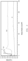
- Fig. 3 includes a plot of the wear rotations vs. the coefficient of friction for the sample S1 and comparative samples CS1 and CS2. The results of the comparison tests are shown in table 1 below.
- Table 1 COF and Wear Life Comparison Sample COF Wear Rating S1 0.023 > 250,000 CS1 0.034 9,700 CS1 0.040 29,500
Landscapes
- Engineering & Computer Science (AREA)
- General Engineering & Computer Science (AREA)
- Mechanical Engineering (AREA)
- Physics & Mathematics (AREA)
- Electromagnetism (AREA)
- Power Engineering (AREA)
- Laminated Bodies (AREA)
- Sliding-Contact Bearings (AREA)
- Compositions Of Macromolecular Compounds (AREA)
Claims (15)
- Reibungsarme Lagerbuchse (100, 230) für ein Solenoid (200), wobei die reibungsarme Lagerbuchse (100, 230) umfasst:eine Kernschicht (110), umfassend ein Polyimidmaterial;eine erste Außenschicht (120), die über einer ersten Oberfläche (112) der Kernschicht (110) liegt, wobei die erste Außenschicht (120) ein Fluorpolymermaterial umfasst und wobei die erste Außenschicht (120) einen Schmelzflussrate von mindestens etwa 2 g/10 min bei 372 °C aufweist;eine zweite Außenschicht (130), die über der ersten Außenschicht (120) liegt, wobei die zweite Außenschicht (130) ein Fluorpolymermaterial umfasst, das sich von dem Fluorpolymermaterial der ersten Außenschicht (120) unterscheidet, und wobei die zweite Außenschicht (130) einen Oberflächenreibungskoeffizienten von nicht mehr als etwa 0,2 aufweist;eine erste Innenschicht (140), die über einer zweiten Oberfläche (114) der Kernschicht (110) liegt, wobei die zweite Oberfläche (114) gegenüber der ersten Oberfläche (112) liegt, wobei die erste Innenschicht (140) ein Fluorpolymermaterial umfasst und wobei die erste Innenschicht (140) einen Schmelzflussrate von mindestens etwa 2 g/10 min bei 372 °C aufweist; undeine zweite Innenschicht (150), die über der ersten Innenschicht (140) liegt, wobei die zweite Innenschicht (150) ein Fluorpolymermaterial umfasst, das sich von dem Fluorpolymermaterial der ersten Innenschicht (140) unterscheidet, und wobei die zweite Innenschicht (150) einen Oberflächenreibungskoeffizienten von nicht mehr als etwa 0,2 aufweist;wobei der Oberflächenreibungskoeffizient einer bestimmten Schicht unter einer Normalkraft von 9 Newton bei 260 mm/s in Kontakt mit einer Polyimidverschleißkugel von 6,35 mm (0,25 Zoll) bei einer Temperatur von 140 °C und geschmiert mit 60 cm2/s (6.000 cs) Silikonöl gemessen wird.
- Reibungsarme Lagerbuchse (100, 230) für ein Solenoid (200), wobei die reibungsarme Lagerbuchse (100, 230) umfasst:eine Kernschicht (110), umfassend ein Polyimidmaterial;eine erste Außenschicht (120), die über einer ersten Oberfläche (112) der Kernschicht (110) liegt, wobei die erste Außenschicht (120) mindestens eines umfasst von einem fluorierten Ethylenpropylenmaterial, einem Perfluoralkoxyalkanmaterial, einem modifizierten PTFE-Material oder einer Kombination davon;eine zweite Außenschicht (130), die über der ersten Außenschicht (120) liegt, wobei die zweite Außenschicht (130) mindestens eines umfasst von einem Polytetrafluorethylenmaterial oder einer Mischung aus einem Polytetrafluorethylenmaterial und einem fluorierten Ethylenpropylenmaterial, einem Perfluoralkoxyalkanmaterial oder einem modifizierten PTFE-Material;eine erste Innenschicht (140), die über einer zweiten Oberfläche (114) der Kernschicht (110) liegt, wobei die zweite Oberfläche (114) gegenüber der ersten Oberfläche (112) liegt, wobei die erste Innenschicht (140) mindestens eines umfasst von einem fluorierten Ethylenpropylenmaterial, einem Perfluoralkoxyalkanmaterial, einem modifizierten PTFE-Material oder einer Kombination davon; undeine zweite Innenschicht (150), die über der ersten Innenschicht (140) liegt, wobei die zweite Innenschicht (150) mindestens eines umfasst von einem Polytetrafluorethylenmaterial oder einer Mischung aus einem Polytetrafluorethylenmaterial und einem fluorierten Ethylenpropylenmaterial, einem Perfluoralkoxyalkanmaterial oder einem modifizierten PTFE-Material.
- Reibungsarme Lagerbuchse (100, 230) nach Anspruch 2, wobei die erste Außenschicht (120) einen Schmelzflussrate von mindestens etwa 2 g/10 min bei 372 °C aufweist.
- Reibungsarme Lagerbuchse (100, 230) nach Anspruch 2, wobei die zweite Außenschicht (130) einen Oberflächenreibungskoeffizienten von nicht mehr als etwa 0,2 aufweist, wobei der Oberflächenreibungskoeffizient unter einer Normalkraft von 9 Newton bei 260 mm/s in Kontakt mit einer Polyimidverschleißkugel von 6,35 mm (0,25 Zoll) bei einer Temperatur von 140 °C und geschmiert mit 60 cm2/s (6.000 cs) Silikonöl gemessen wird.
- Reibungsarme Lagerbuchse (100, 230) nach Anspruch 2, wobei die erste Innenschicht (140) einen Schmelzflussrate von mindestens etwa 2 g/10 min bei 372 °C aufweist.
- Reibungsarme Lagerbuchse (100, 230) nach Anspruch 2, wobei die zweite Innenschicht (150) einen Oberflächenreibungskoeffizienten von nicht mehr als etwa 0,2 aufweist, wobei der Oberflächenreibungskoeffizient unter einer Normalkraft von 9 Newton bei 260 mm/s in Kontakt mit einer Polyimidverschleißkugel von 6,35 mm (0,25 Zoll) bei einer Temperatur von 140 °C und geschmiert mit 60 cm2/s (6.000 cs) Silikonöl gemessen wird.
- Reibungsarme Lagerbuchse (100, 230) nach Anspruch 1, wobei die erste Außenschicht (120) mindestens eines umfasst von einem fluorierten Ethylenpropylenmaterial, einem Perfluoralkoxyalkanmaterial, einem modifizierten PTFE-Material oder einer Kombination davon.
- Reibungsarme Lagerbuchse (100, 230) nach Anspruch 1, wobei die zweite Außenschicht (130) ein Polytetrafluorethylenmaterial oder eine Mischung aus einem Polytetrafluorethylenmaterial und einem fluorierten Ethylenpropylenmaterial, ein Perfluoralkoxyalkanmaterial, ein modifiziertes PTFE-Material umfasst.
- Reibungsarme Lagerbuchse (100, 230) nach Anspruch 1, wobei die erste Innenschicht (140) mindestens eines umfasst von einem fluorierten Ethylenpropylenmaterial, einem Perfluoralkoxyalkanmaterial, einem modifizierten PTFE-Material oder einer Kombination davon.
- Reibungsarme Lagerbuchse (100, 230) nach Anspruch 1, wobei die zweite Innenschicht (150) ein Polytetrafluorethylenmaterial oder eine Mischung aus einem Polytetrafluorethylenmaterial und einem fluorierten Ethylenpropylenmaterial, ein Perfluoralkoxyalkanmaterial, ein modifiziertes PTFE-Material umfasst.
- Reibungsarme Lagerbuchse (100, 230) nach einem der Ansprüche 1 und 2, ferner umfassend eine Verschleißbewertung von mindestens ungefähr 32.000, wobei die Verschleißbewertung gleich der Anzahl von Umdrehungen ist, die vor einem Versagen in einem Tribometertest abgeschlossen werden, und das Versagen als Anstieg des COF von 50 % gegenüber einem stationären Wert während des Tribometertests definiert ist.
- Reibungsarme Lagerbuchse (100, 230) nach einem der Ansprüche 1 und 2, ferner umfassend ein Dickenverhältnis FOLT/CLT der ersten Außenschicht (120) von mindestens etwa 0,02 und nicht größer als etwa 0,4, wobei FOLT gleich der Dicke der ersten Außenschicht ist und CLT gleich der Dicke der Kernschicht (110) ist.
- Reibungsarme Lagerbuchse (100, 230) nach einem der Ansprüche 1 und 2, ferner umfassend ein Dickenverhältnis SOLT/CLT der zweiten Außenschicht (130) von mindestens etwa 0,02 und nicht größer als etwa 0,4, wobei SOLT gleich der Dicke der zweiten Außenschicht ist und CLT gleich der Dicke der Kernschicht (110) ist.
- Reibungsarme Lagerbuchse (100, 230) nach einem der Ansprüche 1 und 2, ferner umfassend ein Dickenverhältnis FILT/CLT der ersten Innenschicht (140) von mindestens etwa 0,02 und nicht größer als etwa 0,4, wobei FILT gleich der Dicke der ersten Innenschicht (140) ist und CLT gleich der Dicke der Kernschicht (110) ist, und ein Dickenverhältnis SILT/CLT der zweiten Innenschicht (150) von mindestens etwa 0,02 und nicht größer als etwa 0,4, wobei SILT gleich der Dicke der zweiten Innenschicht (150) ist und CLT gleich der Dicke der Kernschicht (110) ist.
- Solenoid (200), umfassend:einen Zylinder (210);einen Anker (220) innerhalb des Zylinders (210); unddie reibungsarme Lagerbuchse (100, 230) nach Anspruch 1, die zwischen einer Innenoberfläche des Zylinders (210) und einer Außenoberfläche des Ankers (220) angeordnet ist.
Priority Applications (1)
| Application Number | Priority Date | Filing Date | Title |
|---|---|---|---|
| EP25159578.1A EP4534867A3 (de) | 2018-12-27 | 2019-12-18 | Reibungsarme solenoidlagerauskleidung |
Applications Claiming Priority (2)
| Application Number | Priority Date | Filing Date | Title |
|---|---|---|---|
| US201862785488P | 2018-12-27 | 2018-12-27 | |
| PCT/US2019/067018 WO2020139640A1 (en) | 2018-12-27 | 2019-12-18 | Solenoid low friction bearing liner |
Related Child Applications (1)
| Application Number | Title | Priority Date | Filing Date |
|---|---|---|---|
| EP25159578.1A Division EP4534867A3 (de) | 2018-12-27 | 2019-12-18 | Reibungsarme solenoidlagerauskleidung |
Publications (3)
| Publication Number | Publication Date |
|---|---|
| EP3903010A1 EP3903010A1 (de) | 2021-11-03 |
| EP3903010A4 EP3903010A4 (de) | 2022-11-16 |
| EP3903010B1 true EP3903010B1 (de) | 2025-02-26 |
Family
ID=71122639
Family Applications (2)
| Application Number | Title | Priority Date | Filing Date |
|---|---|---|---|
| EP25159578.1A Pending EP4534867A3 (de) | 2018-12-27 | 2019-12-18 | Reibungsarme solenoidlagerauskleidung |
| EP19906198.7A Active EP3903010B1 (de) | 2018-12-27 | 2019-12-18 | Reibungsarme solenoidlagerauskleidung |
Family Applications Before (1)
| Application Number | Title | Priority Date | Filing Date |
|---|---|---|---|
| EP25159578.1A Pending EP4534867A3 (de) | 2018-12-27 | 2019-12-18 | Reibungsarme solenoidlagerauskleidung |
Country Status (8)
| Country | Link |
|---|---|
| US (2) | US11162531B2 (de) |
| EP (2) | EP4534867A3 (de) |
| JP (1) | JP7202466B2 (de) |
| KR (1) | KR102607938B1 (de) |
| CN (1) | CN113272567B (de) |
| MX (1) | MX2021007389A (de) |
| PL (1) | PL3903010T3 (de) |
| WO (1) | WO2020139640A1 (de) |
Families Citing this family (3)
| Publication number | Priority date | Publication date | Assignee | Title |
|---|---|---|---|---|
| JP7168789B2 (ja) | 2018-12-27 | 2022-11-09 | サン-ゴバン パフォーマンス プラスティックス コーポレイション | プリンタアセンブリの低摩擦ローラライナ |
| PL3903010T3 (pl) | 2018-12-27 | 2025-06-09 | Versiv Composites Limited | Tuleja łożyska o małym tarciu do solenoidu |
| US11852194B2 (en) | 2020-12-11 | 2023-12-26 | Saint-Gobain Performance Plastics Corporation | Solenoid low friction bearing liner |
Citations (2)
| Publication number | Priority date | Publication date | Assignee | Title |
|---|---|---|---|---|
| US20110236691A1 (en) * | 2010-03-23 | 2011-09-29 | Sumitomo Electric Fine Polymer, Inc. | Method for producing fixing-unit member and fixing-unit member |
| US20120315418A1 (en) * | 2010-08-31 | 2012-12-13 | Sumitomo Electric Fine Polymer, Inc | Fixing belt |
Family Cites Families (44)
| Publication number | Priority date | Publication date | Assignee | Title |
|---|---|---|---|---|
| US2559750A (en) | 1949-07-27 | 1951-07-10 | Du Pont | Aqueous colloidal dispersions of polytetrafluoroethylene and the formation of shapedstructures therefrom |
| US2559752A (en) | 1951-03-06 | 1951-07-10 | Du Pont | Aqueous colloidal dispersions of polymers |
| US2833686A (en) | 1955-06-20 | 1958-05-06 | Du Pont | Bonding polytetrafluoroethylene resins |
| BE560454A (de) | 1957-03-29 | |||
| US3179614A (en) | 1961-03-13 | 1965-04-20 | Du Pont | Polyamide-acids, compositions thereof, and process for their preparation |
| US3179634A (en) | 1962-01-26 | 1965-04-20 | Du Pont | Aromatic polyimides and the process for preparing them |
| US3616177A (en) | 1969-09-17 | 1971-10-26 | Du Pont | Laminar structures of polyimides and wire insulated therewith |
| US4628003A (en) | 1981-08-07 | 1986-12-09 | Morton Katz | High temperature heat seal film |
| DE3309904A1 (de) * | 1983-03-18 | 1984-09-20 | Mannesmann Rexroth GmbH, 8770 Lohr | Elektromagnet und magnetventil |
| US5106673A (en) | 1989-02-23 | 1992-04-21 | Chemical Fabrics Corporation | Polyimide and fluoropolymer containing films and laminates |
| US5238748A (en) | 1989-02-23 | 1993-08-24 | Chemfab Corporation | Polyimide and fluoropolymer containing films and laminates |
| JPH0542751U (ja) * | 1991-11-08 | 1993-06-11 | エヌデーシー株式会社 | ソレノイド装置のすべり軸受 |
| CA2106258C (en) | 1992-09-18 | 2003-11-04 | Gautam P. Shah | Moisture barrier film |
| JP3128023B2 (ja) * | 1992-10-30 | 2001-01-29 | トヨタ自動車株式会社 | 摺動皮膜の形成方法 |
| US5731088A (en) | 1996-06-04 | 1998-03-24 | E. I. Du Pont De Nemours And Company | Multilayer polyimide-fluoropolymer insulation having superior cut-through resistance |
| WO2000029210A1 (fr) * | 1998-11-18 | 2000-05-25 | Daikin Industries, Ltd. | Structure polymere contenant du fluor a adhesivite haute temperature, et materiau de glissement utilisant ladite structure |
| EP1229259A1 (de) | 1999-11-12 | 2002-08-07 | Daikin Industries, Ltd. | Zylindrischer artikel und dessen herstellungsverfahren |
| CA2393279A1 (en) | 2000-07-24 | 2002-01-31 | E.I. Du Pont De Nemours And Company | Laser-induced thermal transfer recording process |
| US6630047B2 (en) | 2001-05-21 | 2003-10-07 | 3M Innovative Properties Company | Fluoropolymer bonding composition and method |
| US6994474B2 (en) | 2001-05-29 | 2006-02-07 | Nsk Ltd. | Rolling sliding member and rolling apparatus |
| DE60225928T2 (de) * | 2001-09-18 | 2009-04-16 | Entegris, Inc., Chaska | Hochfeste, chemisch beständige laminarfolie mit begrenzten extraktionsfähigen stoffen |
| DE202005006296U1 (de) * | 2005-04-20 | 2005-07-07 | Bürkert Werke GmbH & Co. KG | Elektromagneteinheit |
| JP5024913B2 (ja) | 2005-06-21 | 2012-09-12 | 株式会社リコー | 画像形成装置 |
| TW200714464A (en) | 2005-07-08 | 2007-04-16 | Arkema France | Multilayer composition |
| AT503986B1 (de) * | 2006-08-02 | 2008-05-15 | Miba Gleitlager Gmbh | Laufschicht für ein lagerelement |
| CN101939796B (zh) * | 2007-12-28 | 2012-11-21 | 钟渊得克萨斯公司 | 具有改善的粘合强度的聚酰亚胺和含氟聚合物粘合层 |
| US20100034919A1 (en) | 2008-08-08 | 2010-02-11 | E. I. Du Pont De Nemours And Company | Melt Processible Semicrystalline Fluoropolymer having Repeating Units Arising from Tetrafluoroethylene, Hexafluoropropylene, and Hydrocarbon Monomer Having a Carboxyl Group and a Polymerizable Carbon-Carbon Double Bond and Multi-Layer Articles Comprising a Layer of the Melt Processible Semicrystalline Fluoropolymer |
| JP5405900B2 (ja) | 2009-02-03 | 2014-02-05 | シャープ株式会社 | 定着装置および画像形成装置 |
| US8121528B2 (en) | 2009-06-24 | 2012-02-21 | Xerox Corporation | Apparatuses useful for printing and methods of treating marking material on media |
| BR112013006817A2 (pt) * | 2010-09-28 | 2016-07-12 | Saint Gobain Performance Plast | método, casquilho e casquilho formado pelo método |
| US9297416B2 (en) | 2011-04-29 | 2016-03-29 | Saint-Gobain Performance Plastics Pampus Gmbh | Maintenance-free slide bearing with FEP or PFA in the adhesive layer |
| EP2707425A1 (de) * | 2011-05-13 | 2014-03-19 | E. I. Du Pont de Nemours and Company | Verschleissarme fluoropolymerverbundstoffe |
| FR2985215B1 (fr) | 2011-12-28 | 2014-09-19 | Saint Gobain Performance Plast | Revetements polymeres deposes sur des substrats par des techniques de projection thermique |
| JP2014186303A (ja) | 2013-02-25 | 2014-10-02 | Ricoh Co Ltd | 定着装置および画像形成装置 |
| JP6197658B2 (ja) | 2014-01-14 | 2017-09-20 | 富士ゼロックス株式会社 | 定着装置、摺動部材および画像形成装置 |
| JP6172001B2 (ja) | 2014-03-18 | 2017-08-02 | 富士ゼロックス株式会社 | 定着装置用部材、定着装置、及び画像形成装置 |
| US20150307670A1 (en) * | 2014-04-25 | 2015-10-29 | Saint-Gobain Performance Plastics Corporation | Thin low friction liners |
| JP6446916B2 (ja) | 2014-08-28 | 2019-01-09 | 富士ゼロックス株式会社 | 定着部材、定着装置、画像形成装置 |
| DE102014218319A1 (de) * | 2014-09-12 | 2015-09-24 | Schaeffler Technologies AG & Co. KG | Gleitlagerkomponente und Lageranordnung mit dieser |
| JP2018049093A (ja) | 2016-09-21 | 2018-03-29 | キヤノンファインテックニスカ株式会社 | 発熱ユニット、定着装置及び画像形成装置 |
| JP6934745B2 (ja) * | 2017-04-26 | 2021-09-15 | 住友電工ファインポリマー株式会社 | 摺動部品及び摺動部品の製造方法 |
| CN206840887U (zh) * | 2017-05-11 | 2018-01-05 | 南京中鸿润宁新材料科技有限公司 | 一种聚酰亚胺套管 |
| PL3903010T3 (pl) | 2018-12-27 | 2025-06-09 | Versiv Composites Limited | Tuleja łożyska o małym tarciu do solenoidu |
| JP7168789B2 (ja) * | 2018-12-27 | 2022-11-09 | サン-ゴバン パフォーマンス プラスティックス コーポレイション | プリンタアセンブリの低摩擦ローラライナ |
-
2019
- 2019-12-18 PL PL19906198.7T patent/PL3903010T3/pl unknown
- 2019-12-18 WO PCT/US2019/067018 patent/WO2020139640A1/en not_active Ceased
- 2019-12-18 US US16/718,278 patent/US11162531B2/en active Active
- 2019-12-18 KR KR1020217023752A patent/KR102607938B1/ko active Active
- 2019-12-18 EP EP25159578.1A patent/EP4534867A3/de active Pending
- 2019-12-18 MX MX2021007389A patent/MX2021007389A/es unknown
- 2019-12-18 EP EP19906198.7A patent/EP3903010B1/de active Active
- 2019-12-18 JP JP2021536376A patent/JP7202466B2/ja active Active
- 2019-12-18 CN CN201980086646.7A patent/CN113272567B/zh active Active
-
2021
- 2021-09-30 US US17/449,491 patent/US11708857B2/en active Active
Patent Citations (2)
| Publication number | Priority date | Publication date | Assignee | Title |
|---|---|---|---|---|
| US20110236691A1 (en) * | 2010-03-23 | 2011-09-29 | Sumitomo Electric Fine Polymer, Inc. | Method for producing fixing-unit member and fixing-unit member |
| US20120315418A1 (en) * | 2010-08-31 | 2012-12-13 | Sumitomo Electric Fine Polymer, Inc | Fixing belt |
Also Published As
| Publication number | Publication date |
|---|---|
| KR102607938B1 (ko) | 2023-12-01 |
| US11708857B2 (en) | 2023-07-25 |
| CN113272567B (zh) | 2023-04-18 |
| PL3903010T3 (pl) | 2025-06-09 |
| JP2022514796A (ja) | 2022-02-15 |
| EP3903010A1 (de) | 2021-11-03 |
| EP4534867A3 (de) | 2025-06-04 |
| MX2021007389A (es) | 2021-09-30 |
| CN113272567A (zh) | 2021-08-17 |
| EP3903010A4 (de) | 2022-11-16 |
| US11162531B2 (en) | 2021-11-02 |
| US20220018397A1 (en) | 2022-01-20 |
| JP7202466B2 (ja) | 2023-01-11 |
| US20200208681A1 (en) | 2020-07-02 |
| KR20210096696A (ko) | 2021-08-05 |
| EP4534867A2 (de) | 2025-04-09 |
| WO2020139640A1 (en) | 2020-07-02 |
Similar Documents
| Publication | Publication Date | Title |
|---|---|---|
| EP3903010B1 (de) | Reibungsarme solenoidlagerauskleidung | |
| EP2621722B1 (de) | Gegossener fluorpolymerfilm für buchsen | |
| US11220120B2 (en) | Printer assembly low friction roller liner | |
| JP2001511502A (ja) | 自己潤滑軸受け | |
| US20190186539A1 (en) | Sliding Member and Bearing | |
| US11261914B2 (en) | Sliding member and bearing | |
| US12247619B2 (en) | Solenoid low friction bearing liner | |
| EP3751162A1 (de) | Gleitelement und lager | |
| US20220184981A1 (en) | Printer assembly low friction roller liner | |
| EP3726080B1 (de) | Gleitelement und lager |
Legal Events
| Date | Code | Title | Description |
|---|---|---|---|
| STAA | Information on the status of an ep patent application or granted ep patent |
Free format text: STATUS: THE INTERNATIONAL PUBLICATION HAS BEEN MADE |
|
| PUAI | Public reference made under article 153(3) epc to a published international application that has entered the european phase |
Free format text: ORIGINAL CODE: 0009012 |
|
| STAA | Information on the status of an ep patent application or granted ep patent |
Free format text: STATUS: REQUEST FOR EXAMINATION WAS MADE |
|
| 17P | Request for examination filed |
Effective date: 20210618 |
|
| AK | Designated contracting states |
Kind code of ref document: A1 Designated state(s): AL AT BE BG CH CY CZ DE DK EE ES FI FR GB GR HR HU IE IS IT LI LT LU LV MC MK MT NL NO PL PT RO RS SE SI SK SM TR |
|
| DAV | Request for validation of the european patent (deleted) | ||
| DAX | Request for extension of the european patent (deleted) | ||
| A4 | Supplementary search report drawn up and despatched |
Effective date: 20221018 |
|
| RIC1 | Information provided on ipc code assigned before grant |
Ipc: F16C 33/20 20060101ALI20221012BHEP Ipc: F16C 17/02 20060101ALI20221012BHEP Ipc: F16C 33/12 20060101AFI20221012BHEP |
|
| GRAP | Despatch of communication of intention to grant a patent |
Free format text: ORIGINAL CODE: EPIDOSNIGR1 |
|
| STAA | Information on the status of an ep patent application or granted ep patent |
Free format text: STATUS: GRANT OF PATENT IS INTENDED |
|
| INTG | Intention to grant announced |
Effective date: 20240326 |
|
| GRAJ | Information related to disapproval of communication of intention to grant by the applicant or resumption of examination proceedings by the epo deleted |
Free format text: ORIGINAL CODE: EPIDOSDIGR1 |
|
| STAA | Information on the status of an ep patent application or granted ep patent |
Free format text: STATUS: REQUEST FOR EXAMINATION WAS MADE |
|
| INTC | Intention to grant announced (deleted) | ||
| RAP1 | Party data changed (applicant data changed or rights of an application transferred) |
Owner name: VERSIV COMPOSITES LIMITED |
|
| GRAP | Despatch of communication of intention to grant a patent |
Free format text: ORIGINAL CODE: EPIDOSNIGR1 |
|
| STAA | Information on the status of an ep patent application or granted ep patent |
Free format text: STATUS: GRANT OF PATENT IS INTENDED |
|
| INTG | Intention to grant announced |
Effective date: 20241004 |
|
| GRAS | Grant fee paid |
Free format text: ORIGINAL CODE: EPIDOSNIGR3 |
|
| GRAA | (expected) grant |
Free format text: ORIGINAL CODE: 0009210 |
|
| STAA | Information on the status of an ep patent application or granted ep patent |
Free format text: STATUS: THE PATENT HAS BEEN GRANTED |
|
| AK | Designated contracting states |
Kind code of ref document: B1 Designated state(s): AL AT BE BG CH CY CZ DE DK EE ES FI FR GB GR HR HU IE IS IT LI LT LU LV MC MK MT NL NO PL PT RO RS SE SI SK SM TR |
|
| REG | Reference to a national code |
Ref country code: GB Ref legal event code: FG4D |
|
| REG | Reference to a national code |
Ref country code: CH Ref legal event code: EP |
|
| REG | Reference to a national code |
Ref country code: DE Ref legal event code: R096 Ref document number: 602019066671 Country of ref document: DE |
|
| REG | Reference to a national code |
Ref country code: IE Ref legal event code: FG4D |
|
| REG | Reference to a national code |
Ref country code: NL Ref legal event code: MP Effective date: 20250226 |
|
| PG25 | Lapsed in a contracting state [announced via postgrant information from national office to epo] |
Ref country code: RS Free format text: LAPSE BECAUSE OF FAILURE TO SUBMIT A TRANSLATION OF THE DESCRIPTION OR TO PAY THE FEE WITHIN THE PRESCRIBED TIME-LIMIT Effective date: 20250526 |
|
| PG25 | Lapsed in a contracting state [announced via postgrant information from national office to epo] |
Ref country code: FI Free format text: LAPSE BECAUSE OF FAILURE TO SUBMIT A TRANSLATION OF THE DESCRIPTION OR TO PAY THE FEE WITHIN THE PRESCRIBED TIME-LIMIT Effective date: 20250226 |
|
| PG25 | Lapsed in a contracting state [announced via postgrant information from national office to epo] |
Ref country code: ES Free format text: LAPSE BECAUSE OF FAILURE TO SUBMIT A TRANSLATION OF THE DESCRIPTION OR TO PAY THE FEE WITHIN THE PRESCRIBED TIME-LIMIT Effective date: 20250226 |
|
| REG | Reference to a national code |
Ref country code: LT Ref legal event code: MG9D |
|
| PG25 | Lapsed in a contracting state [announced via postgrant information from national office to epo] |
Ref country code: NO Free format text: LAPSE BECAUSE OF FAILURE TO SUBMIT A TRANSLATION OF THE DESCRIPTION OR TO PAY THE FEE WITHIN THE PRESCRIBED TIME-LIMIT Effective date: 20250526 Ref country code: IS Free format text: LAPSE BECAUSE OF FAILURE TO SUBMIT A TRANSLATION OF THE DESCRIPTION OR TO PAY THE FEE WITHIN THE PRESCRIBED TIME-LIMIT Effective date: 20250626 |
|
| PG25 | Lapsed in a contracting state [announced via postgrant information from national office to epo] |
Ref country code: NL Free format text: LAPSE BECAUSE OF FAILURE TO SUBMIT A TRANSLATION OF THE DESCRIPTION OR TO PAY THE FEE WITHIN THE PRESCRIBED TIME-LIMIT Effective date: 20250226 |
|
| PG25 | Lapsed in a contracting state [announced via postgrant information from national office to epo] |
Ref country code: HR Free format text: LAPSE BECAUSE OF FAILURE TO SUBMIT A TRANSLATION OF THE DESCRIPTION OR TO PAY THE FEE WITHIN THE PRESCRIBED TIME-LIMIT Effective date: 20250226 |
|
| PG25 | Lapsed in a contracting state [announced via postgrant information from national office to epo] |
Ref country code: PT Free format text: LAPSE BECAUSE OF FAILURE TO SUBMIT A TRANSLATION OF THE DESCRIPTION OR TO PAY THE FEE WITHIN THE PRESCRIBED TIME-LIMIT Effective date: 20250626 Ref country code: LV Free format text: LAPSE BECAUSE OF FAILURE TO SUBMIT A TRANSLATION OF THE DESCRIPTION OR TO PAY THE FEE WITHIN THE PRESCRIBED TIME-LIMIT Effective date: 20250226 |
|
| PG25 | Lapsed in a contracting state [announced via postgrant information from national office to epo] |
Ref country code: GR Free format text: LAPSE BECAUSE OF FAILURE TO SUBMIT A TRANSLATION OF THE DESCRIPTION OR TO PAY THE FEE WITHIN THE PRESCRIBED TIME-LIMIT Effective date: 20250527 Ref country code: BG Free format text: LAPSE BECAUSE OF FAILURE TO SUBMIT A TRANSLATION OF THE DESCRIPTION OR TO PAY THE FEE WITHIN THE PRESCRIBED TIME-LIMIT Effective date: 20250226 |
|
| REG | Reference to a national code |
Ref country code: AT Ref legal event code: MK05 Ref document number: 1770883 Country of ref document: AT Kind code of ref document: T Effective date: 20250226 |
|
| PG25 | Lapsed in a contracting state [announced via postgrant information from national office to epo] |
Ref country code: SE Free format text: LAPSE BECAUSE OF FAILURE TO SUBMIT A TRANSLATION OF THE DESCRIPTION OR TO PAY THE FEE WITHIN THE PRESCRIBED TIME-LIMIT Effective date: 20250226 |
|
| PG25 | Lapsed in a contracting state [announced via postgrant information from national office to epo] |
Ref country code: SM Free format text: LAPSE BECAUSE OF FAILURE TO SUBMIT A TRANSLATION OF THE DESCRIPTION OR TO PAY THE FEE WITHIN THE PRESCRIBED TIME-LIMIT Effective date: 20250226 |
|
| PG25 | Lapsed in a contracting state [announced via postgrant information from national office to epo] |
Ref country code: DK Free format text: LAPSE BECAUSE OF FAILURE TO SUBMIT A TRANSLATION OF THE DESCRIPTION OR TO PAY THE FEE WITHIN THE PRESCRIBED TIME-LIMIT Effective date: 20250226 |
|
| PG25 | Lapsed in a contracting state [announced via postgrant information from national office to epo] |
Ref country code: AT Free format text: LAPSE BECAUSE OF FAILURE TO SUBMIT A TRANSLATION OF THE DESCRIPTION OR TO PAY THE FEE WITHIN THE PRESCRIBED TIME-LIMIT Effective date: 20250226 |
|
| PG25 | Lapsed in a contracting state [announced via postgrant information from national office to epo] |
Ref country code: CZ Free format text: LAPSE BECAUSE OF FAILURE TO SUBMIT A TRANSLATION OF THE DESCRIPTION OR TO PAY THE FEE WITHIN THE PRESCRIBED TIME-LIMIT Effective date: 20250226 Ref country code: EE Free format text: LAPSE BECAUSE OF FAILURE TO SUBMIT A TRANSLATION OF THE DESCRIPTION OR TO PAY THE FEE WITHIN THE PRESCRIBED TIME-LIMIT Effective date: 20250226 |
|
| PG25 | Lapsed in a contracting state [announced via postgrant information from national office to epo] |
Ref country code: SK Free format text: LAPSE BECAUSE OF FAILURE TO SUBMIT A TRANSLATION OF THE DESCRIPTION OR TO PAY THE FEE WITHIN THE PRESCRIBED TIME-LIMIT Effective date: 20250226 |
|
| REG | Reference to a national code |
Ref country code: DE Ref legal event code: R097 Ref document number: 602019066671 Country of ref document: DE |
|
| PLBE | No opposition filed within time limit |
Free format text: ORIGINAL CODE: 0009261 |
|
| STAA | Information on the status of an ep patent application or granted ep patent |
Free format text: STATUS: NO OPPOSITION FILED WITHIN TIME LIMIT |
|
| PGFP | Annual fee paid to national office [announced via postgrant information from national office to epo] |
Ref country code: DE Payment date: 20251028 Year of fee payment: 7 |
|
| PGFP | Annual fee paid to national office [announced via postgrant information from national office to epo] |
Ref country code: GB Payment date: 20251030 Year of fee payment: 7 |
|
| PGFP | Annual fee paid to national office [announced via postgrant information from national office to epo] |
Ref country code: IT Payment date: 20251121 Year of fee payment: 7 |
|
| PGFP | Annual fee paid to national office [announced via postgrant information from national office to epo] |
Ref country code: FR Payment date: 20251110 Year of fee payment: 7 |
|
| PGFP | Annual fee paid to national office [announced via postgrant information from national office to epo] |
Ref country code: BE Payment date: 20251117 Year of fee payment: 7 |
|
| PGFP | Annual fee paid to national office [announced via postgrant information from national office to epo] |
Ref country code: IE Payment date: 20251111 Year of fee payment: 7 |
|
| PGFP | Annual fee paid to national office [announced via postgrant information from national office to epo] |
Ref country code: PL Payment date: 20251117 Year of fee payment: 7 |
|
| PGFP | Annual fee paid to national office [announced via postgrant information from national office to epo] |
Ref country code: RO Payment date: 20251128 Year of fee payment: 7 |
|
| 26N | No opposition filed |
Effective date: 20251127 |