EP3900564B1 - Bewegliches stirnschild - Google Patents
Bewegliches stirnschild Download PDFInfo
- Publication number
- EP3900564B1 EP3900564B1 EP20170849.2A EP20170849A EP3900564B1 EP 3900564 B1 EP3900564 B1 EP 3900564B1 EP 20170849 A EP20170849 A EP 20170849A EP 3900564 B1 EP3900564 B1 EP 3900564B1
- Authority
- EP
- European Patent Office
- Prior art keywords
- visor
- helmet
- shield
- forehead
- protective helmet
- Prior art date
- Legal status (The legal status is an assumption and is not a legal conclusion. Google has not performed a legal analysis and makes no representation as to the accuracy of the status listed.)
- Active
Links
Images
Classifications
-
- A—HUMAN NECESSITIES
- A42—HEADWEAR
- A42B—HATS; HEAD COVERINGS
- A42B3/00—Helmets; Helmet covers ; Other protective head coverings
- A42B3/003—Helmet covers
-
- A—HUMAN NECESSITIES
- A42—HEADWEAR
- A42B—HATS; HEAD COVERINGS
- A42B3/00—Helmets; Helmet covers ; Other protective head coverings
- A42B3/04—Parts, details or accessories of helmets
- A42B3/18—Face protection devices
-
- A—HUMAN NECESSITIES
- A42—HEADWEAR
- A42B—HATS; HEAD COVERINGS
- A42B3/00—Helmets; Helmet covers ; Other protective head coverings
- A42B3/04—Parts, details or accessories of helmets
- A42B3/18—Face protection devices
- A42B3/185—Securing goggles or spectacles on helmet shells
-
- A—HUMAN NECESSITIES
- A42—HEADWEAR
- A42B—HATS; HEAD COVERINGS
- A42B3/00—Helmets; Helmet covers ; Other protective head coverings
- A42B3/04—Parts, details or accessories of helmets
- A42B3/18—Face protection devices
- A42B3/22—Visors
-
- A—HUMAN NECESSITIES
- A42—HEADWEAR
- A42B—HATS; HEAD COVERINGS
- A42B3/00—Helmets; Helmet covers ; Other protective head coverings
- A42B3/04—Parts, details or accessories of helmets
- A42B3/18—Face protection devices
- A42B3/22—Visors
- A42B3/221—Attaching visors to helmet shells, e.g. on motorcycle helmets
- A42B3/222—Attaching visors to helmet shells, e.g. on motorcycle helmets in an articulated manner, e.g. hinge devices
-
- F—MECHANICAL ENGINEERING; LIGHTING; HEATING; WEAPONS; BLASTING
- F41—WEAPONS
- F41H—ARMOUR; ARMOURED TURRETS; ARMOURED OR ARMED VEHICLES; MEANS OF ATTACK OR DEFENCE, e.g. CAMOUFLAGE, IN GENERAL
- F41H1/00—Personal protection gear
- F41H1/04—Protection helmets
-
- F—MECHANICAL ENGINEERING; LIGHTING; HEATING; WEAPONS; BLASTING
- F41—WEAPONS
- F41H—ARMOUR; ARMOURED TURRETS; ARMOURED OR ARMED VEHICLES; MEANS OF ATTACK OR DEFENCE, e.g. CAMOUFLAGE, IN GENERAL
- F41H1/00—Personal protection gear
- F41H1/04—Protection helmets
- F41H1/06—Protection helmets of steel; Steel head-shields
-
- F—MECHANICAL ENGINEERING; LIGHTING; HEATING; WEAPONS; BLASTING
- F41—WEAPONS
- F41H—ARMOUR; ARMOURED TURRETS; ARMOURED OR ARMED VEHICLES; MEANS OF ATTACK OR DEFENCE, e.g. CAMOUFLAGE, IN GENERAL
- F41H1/00—Personal protection gear
- F41H1/04—Protection helmets
- F41H1/08—Protection helmets of plastics; Plastic head-shields
-
- F—MECHANICAL ENGINEERING; LIGHTING; HEATING; WEAPONS; BLASTING
- F41—WEAPONS
- F41H—ARMOUR; ARMOURED TURRETS; ARMOURED OR ARMED VEHICLES; MEANS OF ATTACK OR DEFENCE, e.g. CAMOUFLAGE, IN GENERAL
- F41H5/00—Armour; Armour plates
- F41H5/013—Mounting or securing armour plates
Definitions
- the present invention relates to a movable face shield for a ballistic protective helmet.
- Ballistic protective helmets to protect the wearer's head have been known in the art for a long time. These serve to protect against direct force, e.g. fire from firearms or indirectly, among other things, through the impact on the wearer's head from splinters and from the impact of cutting and stabbing weapons.
- this type of helmet is worn by special forces and increasingly also by patrol officers who arrive at the scene first (so-called "first responders") with the aim of protecting the wearer's self.
- the protective effect of such a helmet is achieved by stopping an impacting projectile (or splinter) and thus preventing penetration of the helmet into the wearer's head.
- the kinetic energy of the impacting parts should be minimized in order to protect the wearer from lethal effects.
- Typical materials from which the helmet cap of a ballistic protective helmet is made are titanium, aramid or polyethylene.
- a visor which can be set up permanently in front of the face as well as being able to be folded up and down.
- the forehead shield is attached to the helmet cap using a Velcro application, see e.g EP 3 520 641 A1 .
- This method of attachment means that the shield can be detachably attached to the helmet cap in order to be able to supplement the protective effect of the ballistic helmet depending on the situation (if necessary in conjunction with a visor).
- Situational circumstances include, for example, an expected fire from a long weapon or other frontal impacts that the bearer of the shield can address more directly. If the threat situation is classified as lower, the shield can be removed to reduce the weight of the helmet and thus increase the wearing comfort for the wearer.
- the use of an additional shield regularly leads to disadvantages if the helmet is to be used together with a forehead shield and a visor. Due to the spatial expansion of the front shield, it is no longer possible to open a conventional visor (e.g. by folding it up), as this is prevented by the spatial expansion of the front shield. This problem can be avoided by designing the visor in such a way that it is able to slide over the front shield. Due to the weight of the visor and the now extended lever arm, the torque acting on the helmet increases, which leads to a reduction in wearing comfort.
- ITUB20160865 also discloses a face shield for a ballistic protective helmet.
- the invention is therefore based on the object of improving the design of the end shields known from the prior art in such a way that they can also be used in combination with a visor, without the impairments in wearing comfort known from the prior art and without impairing or endangering the safety of the police or emergency services through the way it is set up.
- a front shield for a ballistic protective helmet which is set up to move with the visor when a visor of the protective helmet is opened and closed.
- the forehead shield is attached to the helmet in such a way that a visor can be moved together with the forehead shield.
- the forehead shield can basically be attached to the helmet in a displaceable manner. This offers the advantage that a conventional visor can be used in this way, which therefore offers the already known wearing comfort. There is no need for a visor that slides over the front shield.
- a complex conversion of the helmet is no longer necessary depending on the situation, since the desired functionality of opening and closing (or folding up and down) of the visor is also possible when used together with the forehead shield.
- the present disclosure describes several alternative ways in which the faceplate can be slidably attached to a protective helmet.
- the term “displaceable” does not exclude that the front shield or part of it also rotates in addition to a movement relative to the surface of a helmet cap when the front shield or part of it is moved through a visor of the protective helmet.
- the forehead shield or part of it can be lifted off the helmet surface at the lower edge while the visor moves upwards, i.e. out of the field of vision.
- a rotation then takes place.
- this is not excluded by the term “movable”.
- the front shield has a device for attaching the front shield to the protective helmet in a removable and slidable manner.
- This offers the wearer of the protective helmet the opportunity to adapt to the respective situation To adapt the operating conditions and, in the event of an increased risk situation, to be able to rely on additional ballistic protection, which can be made possible by the front shield.
- a removable forehead shield also offers the possibility of adding a forehead shield to existing helmets or retrofitting them. Velcro applications, for example, are preferred as fastening options.
- a forehead shield is not only understood to mean this actual ballistic part, but also other means, devices and elements which are used, for example, to attach the ballistic part to a protective helmet or to connect it to a visor.
- the aim of the enclosure is to attach the forehead shield to the helmet in a movable but still sufficiently strong and stable manner.
- the enclosure can be, for example, a bag which is designed to hold the ballistic part of the forehead shield and to slide along the surface of the helmet dome. Alternatively, it can be a border that surrounds at least part of the edge of the ballistic part.
- the ballistic part of the front shield Since the ballistic part of the front shield is housed in an enclosure, no mechanical processing of the ballistic part is necessary, which could have a detrimental effect on the protective effect of the front shield. Basically, mechanical processing of the ballistic part of the front shield, such as drill holes, reduces its protective effect.
- the housing also has means for pressing the front shield against an outside of a helmet cap of the protective helmet. On the one hand, this will... Front shield held sufficiently firmly on the helmet cap. On the other hand, it is ensured that at least part of the forehead shield can be sufficiently lifted off the helmet cap when the visor is opened. Such lifting can occur because the front shield is attached to a visor and, when opened, this forms an increasing distance from the helmet cap due to its non-spherical shape and/or an eccentric arrangement of the visor bearings.
- the means or means for pressing the front shield compensate for this lifting movement caused by the visor.
- the enclosure is designed to be detachably connected to a helmet cap. This means that the enclosure can be connected to the helmet if necessary and the helmet can therefore be worn with a forehead shield.
- the enclosure is designed to connect to and be removable from a visor.
- the enclosure can be set up in such a way that it allows attachment to the helmet cap and/or the visor.
- the fastening option is preferably designed using a Velcro application.
- the means for pressing the front shield against an outside of a helmet cap of the protective helmet can be at least one clamping element, which is designed to be attached to at least one visor bearing of the protective helmet.
- the tensioning element can be elastic, for example as a rubber band, and have a loop at at least one end, which is designed to be attached to a visor bearing of a helmet cap.
- the tensioning element can be detachably connected to the housing.
- the tensioning element can be connected to the housing using a Velcro application.
- the tensioning element can be separated from the housing and the housing can be attached to the protective helmet without a tensioning element, for example by means of a counterpart corresponding to the Velcro application.
- This means that the face shield is fixed to the protective helmet and cannot be moved. This may be desired, for example, if the protective helmet is worn without a visor.
- the tensioning element can be attached closer to a side of the housing facing away from a visor of the protective helmet than to a side of the housing facing the visor.
- This arrangement enables the lifting or rotation movement already mentioned when the enclosure is moved by a visor of the protective helmet: Due to the non-spherical shape of the protective helmet and/or an eccentric position of the visor bearings, it occurs at the lower edge of the enclosure where this occurs Visor is in contact, resulting in a lifting movement or rotation of the housing. This can be taken into account by attaching the tensioning element further away from the lower edge of the enclosure than from its upper edge.
- the enclosure can be made of at least one flame-retardant material. In this way, burning of the housing and/or the clamping element during fire can be prevented or at least delayed to such an extent that the end shield is held securely in position even during subsequent fire.
- the end shield according to the invention can have more than one clamping element, for example two clamping elements, which are arranged on opposite sides of the end shield or its ballistic part.
- the device is for attaching the front shield to the protective helmet in a removable and slidable manner, at least one rail which is designed to be attached to the protective helmet and to hold a part of the protective shield in a slidable manner.
- the rail can, for example, be glued to the surface of the helmet or attached to it using a Velcro application.
- the other part of the front shield, in particular the ballistic part is then slidably held on the protective helmet by the rail and - similar to the enclosure mechanism already described previously - is moved by a visor of the protective helmet when opening and closing.
- the displaceable part of the protective shield can have a sliding element which is designed to slide in the rail, which preferably has a T-groove.
- the sliding element can be closer to a side facing away from the visor of the ballistic part of the front shield than on a side facing the visor. In this way, the already mentioned lifting or rotational movement of the movable part of the front shield can also occur with the rail mechanism described here when the visor is opened.
- the sliding element and the rail can be designed so that the sliding part can be inserted into the rail.
- the movable part of the front shield in particular the ballistic element, can be detachably and slidably connected to the helmet cap.
- the forehead shield can further have at least one visor fastening means in order to connect the forehead shield to a visor of the protective helmet.
- the visor fastening means can therefore be present in both the housing solution described herein and in the rail solution.
- the visor attachment means can be attached to the enclosure.
- the visor fastening means can be designed as a Velcro application. Part of this application can be arranged on the visor, e.g. on a visor bar, and the corresponding counterpart on the front shield.
- the visor attachment means may be configured to allow relative rotation between the visor and the faceplate. This means that the lifting or rotational movement of the front shield already described can be supported when opening the visor.
- the front shield can in principle have a fixing means in order to fix the front shield on the protective helmet.
- the protective helmet can be worn with the forehead shield but without the visor.
- the fixing means prevents the front shield from lifting or slipping.
- the visor fastening means and/or the fixing means can be a Velcro application.
- a further aspect of the present invention relates to a protective helmet, comprising (a) a helmet cap; and (b) a face shield as described herein.
- the protective helmet can also have at least one means that interacts with the fixing means of the forehead shield.
- this can be a Velcro fleece application, whereby the Velcro part or the fleece part can be arranged, for example, on the top of the helmet.
- the forehead shield can then be sufficiently fixed, as described above, if the protective helmet is worn without a visor.
- the fixing means can be designed to be foldable. In this way, the fixation means is as inconspicuous as possible when wearing the protective helmet with a visor.
- the protective helmet can have a visor.
- the present invention can be used particularly advantageously in a protective helmet with a visor, since the front shield moves with the visor when it is opened and closed.
- the tensioning element can be formed by an elastic and tensionable material.
- the forehead shield can, on the one hand, simply be pressed against the surface of the helmet and is therefore close to the helmet.
- its flexibility allows the forehead shield to be lifted off the front edge when the visor is opened
- Yet another aspect of the present invention relates to a housing for a ballistic element of a forehead shield for a ballistic protective helmet, wherein the housing is designed to accommodate the ballistic element and has a means for pressing the ballistic element against an outside of a helmet cap of the protective helmet, so that the ballistic element can be attached to the helmet cap in a removable and movable manner.
- the helmet cap can be made of metal, fiber-reinforced plastic and/or a combination of both (hybrid helmet).
- the metal used is, for example, titanium and the fiber-reinforced plastic, for example, is aramid and/or polyethylene fibers.
- a hybrid helmet has proven to be particularly resistant to fire from large-caliber weapons.
- the invention also enables helmets to be retrofitted with an additional forehead shield, whereby the protective helmet can be worn with or without a visor.
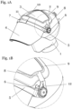
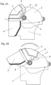
- FIGS. 1A, 1B , 2A and 2B show various views of a preferred embodiment of a forehead shield 3 according to the invention on a protective helmet 2.
- the helmet 2 is a ballistic protective helmet, as can typically be worn by emergency services, such as police or other emergency services, to protect themselves from any kind of external gunfire and/or force.
- the exemplary embodiments of the present invention shown here relate to ballistic protective helmets for special forces and police officers, but are not exclusively limited to these, but can also be used, for example, for protective helmets for military use.
- the helmet cap 2 can be made of metal, fiber-reinforced plastic and/or a combination of both (hybrid helmet).
- titanium is used as metal and aramid and/or polyethylene fibers are used as fiber-reinforced plastic.
- the helmet cap 2 can be produced in a deep-drawing process, preferably from a one-piece titanium sheet, with a single- or multi-layer structure of the cap being possible. It is also possible to make the helmet from steel or aluminum.
- one or more layers made of preferably a fiber composite material made of high molecular weight polyethylene fibers (UHMW-PE) are optionally possible, but are not limited to these. Further layers of aramid fibers can be added to this.
- UHMW-PE high molecular weight polyethylene fibers
- aramid fibers can be added to this.
- other fiber composites can also be considered.
- a combination of materials is referred to as a hybrid.
- the helmet cap 2 can also be made entirely of plastics and/or fiber-rein
- a forehead shield 3 is attached to the ballistic protective helmet 2, which can be worn in combination with a visor 4 (e.g. visual visor).
- the front shield 3 or the actual ballistic element of the front shield is preferably manufactured in such a way that it meets certain requirements of the VPAM (Association of Testing authorities for Attack-Resistant Materials and Construction) testing guidelines, but is not limited to them.
- VPAM Association of Testing authorities for Attack-Resistant Materials and Construction
- the end shield 3 is made of a fiber composite material made of high molecular weight polyethylene fibers (Ultra High Molecular Weight Polyethylene, UHMW-PE), but can in principle also be made of other materials, such as titanium, aluminum, steel or fiber-reinforced plastic, for example made of aramid fibers .
- UHMW-PE Ultra High Molecular Weight Polyethylene
- the front shield or the actual ballistic element 3 is accommodated in a housing 9, which can, for example, have a rubber edging band and, with an additional rubber band 10, prevents the front shield or the ballistic element 3 from slipping or falling out.
- a tensioning element 8 which can be set up, for example, as a rubber band with a tab.
- the enclosure 9 in another embodiment, as can be achieved, for example, by a pocket-like enclosure, which The front shield or the ballistic element 3 can be completely or only partially enclosed and thus encased.
- the enclosure itself can, in addition to a rubber edging, also have other constructions such as a textile element.
- a metallic embodiment of the housing for example as a bent sheet metal part, is also conceivable, in which the end shield is fastened, for example by means of snap fasteners or a clip connection, with the possibility of the embodiments not being limited to the embodiments mentioned.
- the housing 9 and thus the forehead shield accommodated therein or the actual ballistic element 3 is movable along the surface of the helmet cap 2 so that a visor 4 attached to the helmet 2 can be moved up and down.
- the visor 4 is set up as an all-plastic visor (visual visor) according to VPAM2/VPAM3, although other types of visor can also be used with the disclosure according to the invention.
- the visor 4 can also be held by a visor bracket 5 and thus connected to the rest of the protective helmet 2.
- the visor bracket 5 can be rotatably connected to the protective helmet. This can be achieved by attaching corresponding bearings 6 (e.g.
- visor bearings laterally, on both sides of the protective helmet, around which the visor bracket 5 can be rotatably attached/mounted.
- the bearings 6 are preferably attached to the helmet 2 in such a way that they are realized on opposite sides.
- the present invention is not limited to this form of attachment.
- the bearing 6 offers at least one locking point, so that the visor bracket 5 can assume different angles relative to the vertical axis of the wearer. This offers the particular advantage that the visor 4 can be opened and the open visor position can be locked and thus an unwanted folding down of the visor, for example when the wearer is running, can be prevented. Likewise, in a preferred embodiment, at least one further latching point is provided, which stabilizes the closed state of the visor 4. Possible embodiments of the locking points are not those described above Configurations are limited, but any additional locking points can be integrated into the warehouse 6.
- visor bracket and thus the visor 4
- housing 9 and thus the front shield or the ballistic element 3
- Velcro application 7 it is possible to connect the visor bracket (and thus the visor 4) to the housing 9 (and thus the front shield or the ballistic element 3) by means of a Velcro application 7, although other fastening mechanisms are also possible possible are.
- the visor bracket 5 is rotated around the bearing 6, the visor 4 can be folded up or down, with the front shield 3 moving with the visor 4 due to the Velcro application 7, as the front shield 3 slides on the surface of the helmet 2.
- one or more of the helmet components helmet 2, protective shield or ballistic element 3, visor 4, visor bar 5, bearing 6, Velcro applications 7, tensioning element 8, housing 9, and / or rubber band 10 can be made of one or more Several flame-retardant materials can be made, such as leather, Nomex, Kermel, rubber, flame-retardant plastics according to UL94 V-0 and metals, in order to be able to increase the protective effect of the helmet accordingly.
- the Velcro application 7 between the visor bracket 5 and the housing 9 can be arranged in such a way that a kind of hinge 11 results, which makes it possible to create an angle between the housing 9 and the visor bracket 5 (and the visor 4 connected to it). to set.
- the direction of rotation of the visor 4 can be from the head 1 of a wearer outwards (and vice versa).
- the protective helmet 2 can also be worn without a visor within the scope of the present invention.
- static designs are also conceivable, in which the front shield 3 is connected to the helmet cap 2, for example by a further Velcro application 13.
- the front shield 3 can also be used as a retrofit item for an existing protective helmet, which has all the fastening elements required to hold the front shield, but can also be used in combination with a protective helmet as one Type of unit can be purchased.
- the use of the front shield is possible both with an enclosure 9 and without an enclosure 9, although it is also possible here to retrofit a protective helmet with an enclosure to accommodate a protective shield.
- the protective helmet in combination with a movable forehead shield according to the invention (with or without housing), can also be combined with a visor 4 (eg a visual visor), whereby the visor 4 can also be designed as an optional additional retrofit option.
- the retrofitted visor can also be set up to be movable as a unit on the surface of the helmet cap with a retrofitted front shield (with and without housing).
- the at least one clamping element 8 fulfills two relevant functions: On the one hand, the tensioning element ensures that the housing 9 is pressed against the helmet cap 2. Furthermore, the at least one tensioning element 8 serves to enable a joint movement of the housing and visor over the helmet cap, with the housing being lifted off at its lower edge during the movement over the helmet cap surface, due to its non-spherical shape.
- An elastic and tensionable material can, for example, be realized relatively easily using an elastic band or an elastic textile, for example based on elastane.
- the clamping element is designed in such a way that it has a loop-shaped structure 12 at at least one end, which can be used to hang it on at least one bearing and thus, due to the clamping force, the end shield with or without housing against the Press the helmet cap.
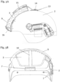
- Fig. 3A shows a side view of a ballistic protective helmet 2 in a further unclaimed embodiment, in which the helmet 2 can be worn without a visor and the associated visor bar.
- the front shield or its ballistic element 3 is also introduced into an enclosure 9 and received by it.
- the enclosure 9 is held in position by means of a loop 13, which is attached to the top of the helmet 2 (preferably by an adhesive connection), and via a fastening element 14 attached to the loop 13 in the form of a Velcro pad.
- the Fastening element 14, which can be connected to the housing 9 via a band, for example, protects the housing 9 from unintentional movement, such as slipping or falling.
- the ballistic element 3 of the front shield can additionally be connected to the housing 9 by a further fastening element 14, thereby preventing the ballistic element 3 from slipping or falling out of the housing 9.
- this holding function is taken over by the Velcro application 7.
- an additional Velcro application 16 which in a preferred embodiment is designed to be folded out, it is possible to establish an additional connection between the helmet 2 and the housing 9.
- the Velcro fleece application 7 is connected to the Velcro fleece application 16. This serves to prevent the housing 9 from unintentionally lifting off and/or slipping from the helmet 2.
- Fig. 3B shows a front view of the ballistic protective helmet 2 of the further unclaimed embodiment Fig. 3A , in which the protective helmet 2 is worn without a visor and only the ballistic element 3 of the forehead shield is attached to the helmet 2 in the housing 9 and is additionally held by the further fastening element 10.
- the Velcro applications 7, 14, 15, 16 it is possible to prevent the housing 9 from unintentionally lifting off and/or slipping away.
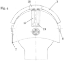
- FIG. 4 shows an alternative solution for a front shield that can be moved with a visor.
- a rail structure 18 of the front shield is attached to the helmet cap 2, which in a preferred embodiment has a T-groove into which a movable part of the front shield is inserted.
- a corresponding recess 19 in the rail structure 17 enables the T-shaped sliding part 18 to be inserted.
- the movable part of the front shield in particular its ballistic element, can thus be pulled forward via the rail structure 17 to the visor bracket 5, to which the visor 4 is attached, and can be connected to it using the Velcro application 7.
- This rail structure 17 also allows the end shield 3 to move along the surface of the helmet cap 2.
- This alternative solution can also be used both with and without a visor.
- the rail structure can be connected to the helmet cap either permanently (e.g. by direct gluing) or removably. If the guide rail is attached to the helmet cap in a removable manner, it can be placed in an unused position
- Embodiment a Velcro application can be used for temporary attachment.
- a stop for the T-shaped sliding part 18 can be provided, which serves in particular to prevent the head shield from unintentionally slipping when the protective helmet 2 is worn without a visor.
- the Velcro fleece applications 7 and 16 can be used for fixation.
- a flexibly configured pair of guide rails which can be attached to the helmet cap both permanently and removably, can also be used to movably mount the forehead shield.
- Plastics, flame-retardant plastics and/or impact-modified plastics according to UL94 V-0 as well as metals are particularly suitable for assembly.
Landscapes
- Engineering & Computer Science (AREA)
- General Engineering & Computer Science (AREA)
- Helmets And Other Head Coverings (AREA)
Priority Applications (9)
| Application Number | Priority Date | Filing Date | Title |
|---|---|---|---|
| PL20170849.2T PL3900564T3 (pl) | 2020-04-22 | 2020-04-22 | Ruchoma osłona czołowa |
| ES20170849T ES2978506T3 (es) | 2020-04-22 | 2020-04-22 | Escudo frontal móvil |
| HRP20240425TT HRP20240425T1 (hr) | 2020-04-22 | 2020-04-22 | Pomični štitnik za čelo |
| EP20170849.2A EP3900564B1 (de) | 2020-04-22 | 2020-04-22 | Bewegliches stirnschild |
| DE202021001121.8U DE202021001121U1 (de) | 2020-04-22 | 2021-03-24 | Bewegliches Stirnschild |
| IL282346A IL282346B2 (en) | 2020-04-22 | 2021-04-14 | Portable forehead protector |
| US17/235,636 US20210330019A1 (en) | 2020-04-22 | 2021-04-20 | Movable forehead shield |
| AU2021202397A AU2021202397A1 (en) | 2020-04-22 | 2021-04-20 | Movable forehead shield |
| CN202110434507.8A CN113532200A (zh) | 2020-04-22 | 2021-04-22 | 可移动前额护罩 |
Applications Claiming Priority (1)
| Application Number | Priority Date | Filing Date | Title |
|---|---|---|---|
| EP20170849.2A EP3900564B1 (de) | 2020-04-22 | 2020-04-22 | Bewegliches stirnschild |
Publications (2)
| Publication Number | Publication Date |
|---|---|
| EP3900564A1 EP3900564A1 (de) | 2021-10-27 |
| EP3900564B1 true EP3900564B1 (de) | 2023-12-27 |
Family
ID=70464830
Family Applications (1)
| Application Number | Title | Priority Date | Filing Date |
|---|---|---|---|
| EP20170849.2A Active EP3900564B1 (de) | 2020-04-22 | 2020-04-22 | Bewegliches stirnschild |
Country Status (9)
| Country | Link |
|---|---|
| US (1) | US20210330019A1 (pl) |
| EP (1) | EP3900564B1 (pl) |
| CN (1) | CN113532200A (pl) |
| AU (1) | AU2021202397A1 (pl) |
| DE (1) | DE202021001121U1 (pl) |
| ES (1) | ES2978506T3 (pl) |
| HR (1) | HRP20240425T1 (pl) |
| IL (1) | IL282346B2 (pl) |
| PL (1) | PL3900564T3 (pl) |
Families Citing this family (6)
| Publication number | Priority date | Publication date | Assignee | Title |
|---|---|---|---|---|
| EP3981275A1 (de) * | 2020-10-06 | 2022-04-13 | Ulbrichts GmbH | Visier für einen ballistischen schutzhelm |
| US20220386734A1 (en) * | 2021-06-04 | 2022-12-08 | Jordan Hunter | Adjustable looped-cord goggle attachable to a helmet |
| CN114468452A (zh) * | 2022-01-25 | 2022-05-13 | 北京阿拉叮特种装备有限公司 | 一种智能ar面罩 |
| EP4305991A1 (de) * | 2022-07-15 | 2024-01-17 | Ulbrichts GmbH | Helmkalotte für einen schutzhelm |
| US12274323B2 (en) * | 2023-06-20 | 2025-04-15 | Ourad Safety Co., Ltd. | Device for connecting lens and earmuff to safety helmet |
| US20250325053A1 (en) * | 2024-04-18 | 2025-10-23 | Joseph Bryan Guzzardi | Eye protection apparatus |
Family Cites Families (14)
| Publication number | Priority date | Publication date | Assignee | Title |
|---|---|---|---|---|
| DE313012C (pl) * | ||||
| US3548411A (en) * | 1969-02-26 | 1970-12-22 | Us Navy | Retractable goggles for helmet |
| US3783452A (en) * | 1972-04-11 | 1974-01-08 | Us Navy | Removable goggles for helmet |
| US5893174A (en) * | 1995-05-22 | 1999-04-13 | Primeau; Charles W. | Non-discard protective facemask/helmet assembly |
| FR2838307B3 (fr) * | 2002-04-16 | 2004-07-09 | Salomon Sa | Ensemble forme par un casque et un masque de protection notamment pour le ski ou la moto |
| CA2658238C (en) * | 2009-03-16 | 2010-05-18 | Danny Higgins | Helmet having a guiding mechanism for a compatible visor and a visor for such a helmet |
| US9222758B2 (en) * | 2011-08-26 | 2015-12-29 | Velocity Systems, Llc | Versatile protective helmet appliqué assembly |
| PL2844098T3 (pl) * | 2012-04-30 | 2016-12-30 | Kask do ochrony mechanicznej, elektrycznej i przed działaniem termicznym, dla elektryków | |
| WO2015030703A1 (en) * | 2013-08-26 | 2015-03-05 | Velocity Systems Llc | Versatile protective helmet applique assembly |
| CN208354713U (zh) * | 2015-06-19 | 2019-01-11 | 奥克利有限公司 | 眼睛佩戴物适配器、头盔、部件、模块化头盔系统和模块化运动头盔 |
| ITUB20160865A1 (it) * | 2016-02-18 | 2017-08-18 | Maurizio Castrati | Elmetto con protezione balistica |
| IT201700021390A1 (it) * | 2017-02-24 | 2018-08-24 | Ci Erre E S R L | Casco protettivo con visiera/occhiale ribaltabile. |
| AU2019215711B2 (en) * | 2018-01-31 | 2022-06-16 | Ulbrichts Gmbh | Ballistic protective helmet |
| HRP20240759T1 (hr) * | 2018-01-31 | 2024-09-13 | Ulbrichts Gmbh | Balistička zaštitna kaciga |
-
2020
- 2020-04-22 EP EP20170849.2A patent/EP3900564B1/de active Active
- 2020-04-22 HR HRP20240425TT patent/HRP20240425T1/hr unknown
- 2020-04-22 ES ES20170849T patent/ES2978506T3/es active Active
- 2020-04-22 PL PL20170849.2T patent/PL3900564T3/pl unknown
-
2021
- 2021-03-24 DE DE202021001121.8U patent/DE202021001121U1/de not_active Expired - Lifetime
- 2021-04-14 IL IL282346A patent/IL282346B2/en unknown
- 2021-04-20 AU AU2021202397A patent/AU2021202397A1/en not_active Abandoned
- 2021-04-20 US US17/235,636 patent/US20210330019A1/en active Pending
- 2021-04-22 CN CN202110434507.8A patent/CN113532200A/zh active Pending
Also Published As
| Publication number | Publication date |
|---|---|
| DE202021001121U1 (de) | 2021-04-01 |
| EP3900564A1 (de) | 2021-10-27 |
| IL282346A (en) | 2021-10-31 |
| CN113532200A (zh) | 2021-10-22 |
| PL3900564T3 (pl) | 2024-06-24 |
| US20210330019A1 (en) | 2021-10-28 |
| ES2978506T3 (es) | 2024-09-13 |
| AU2021202397A1 (en) | 2021-11-11 |
| IL282346B2 (en) | 2025-04-01 |
| IL282346B1 (en) | 2024-12-01 |
| HRP20240425T1 (hr) | 2024-06-21 |
Similar Documents
| Publication | Publication Date | Title |
|---|---|---|
| EP3900564B1 (de) | Bewegliches stirnschild | |
| DE102009042455B4 (de) | Tragsystem mit einer ballistischen Schutzweste | |
| AT516055B1 (de) | Schutzhelm | |
| DE69814405T2 (de) | Kopfbedeckung mit einer gelenkartigen befestigungsvorrichtung für ein visier | |
| DE60100845T2 (de) | Schutzhelm mit vorrichtung zum verstellen der kopfweite | |
| EP1841338B1 (de) | Helm | |
| EP3054801B1 (de) | Schutzhelm | |
| DE102007048106A1 (de) | Schutzweste | |
| DE2442881A1 (de) | Kopfschutz | |
| DE102008021487B4 (de) | Klappwinkelspiegel und Einblickvorrichtung für Klappwinkelspiegel | |
| EP2057910B1 (de) | Schutzhelmsystem | |
| AT1298U1 (de) | Schutzhelm | |
| EP0012334A1 (de) | Tragbarer Schutzschild | |
| EP1843123B1 (de) | Schutzeinrichtung an einer Ein-/Ausstiegsluke eines Kampffahrzeugs, insbesondere eines Kampfpanzers | |
| DE29605503U1 (de) | Körperschutzpanzerung und Körperschutzweste oder -jacke hierfür | |
| DE10050310C1 (de) | Sturzhelm | |
| DE29608345U1 (de) | Helm, insbesondere für den Arbeits-, Brand- und Katastrophenschutz | |
| CH666344A5 (en) | Anti-bullet and splinter helmet for security personnel - has shell with titanium outer layer, inner cover of woven plastic between resilient layers, carrier cage, and titanium visor | |
| DE20318934U1 (de) | Tragbares Schutzschild | |
| DE69823775T2 (de) | Militärischer Schutzhelm | |
| EP3764053B1 (de) | Körperschutzpanzerung mit lösbarem schulterschutz | |
| EP4212049A1 (de) | Aussensystem für einen schutzhelm | |
| EP4602967A1 (de) | Helmkalotte für einen schutzhelm mit verstärkungsschicht | |
| DE202007006105U1 (de) | Schutzhelm mit ballistischer Haube | |
| DE102022132430A1 (de) | Modulares Helmsystem |
Legal Events
| Date | Code | Title | Description |
|---|---|---|---|
| REG | Reference to a national code |
Ref country code: HR Ref legal event code: TUEP Ref document number: P20240425T Country of ref document: HR |
|
| PUAI | Public reference made under article 153(3) epc to a published international application that has entered the european phase |
Free format text: ORIGINAL CODE: 0009012 |
|
| STAA | Information on the status of an ep patent application or granted ep patent |
Free format text: STATUS: THE APPLICATION HAS BEEN PUBLISHED |
|
| AK | Designated contracting states |
Kind code of ref document: A1 Designated state(s): AL AT BE BG CH CY CZ DE DK EE ES FI FR GB GR HR HU IE IS IT LI LT LU LV MC MK MT NL NO PL PT RO RS SE SI SK SM TR |
|
| B565 | Issuance of search results under rule 164(2) epc |
Effective date: 20200915 |
|
| STAA | Information on the status of an ep patent application or granted ep patent |
Free format text: STATUS: REQUEST FOR EXAMINATION WAS MADE |
|
| 17P | Request for examination filed |
Effective date: 20220427 |
|
| RBV | Designated contracting states (corrected) |
Designated state(s): AL AT BE BG CH CY CZ DE DK EE ES FI FR GB GR HR HU IE IS IT LI LT LU LV MC MK MT NL NO PL PT RO RS SE SI SK SM TR |
|
| RIC1 | Information provided on ipc code assigned before grant |
Ipc: F41H 1/08 20060101ALI20230512BHEP Ipc: F41H 1/06 20060101ALI20230512BHEP Ipc: A42B 3/18 20060101AFI20230512BHEP |
|
| GRAP | Despatch of communication of intention to grant a patent |
Free format text: ORIGINAL CODE: EPIDOSNIGR1 |
|
| STAA | Information on the status of an ep patent application or granted ep patent |
Free format text: STATUS: GRANT OF PATENT IS INTENDED |
|
| INTG | Intention to grant announced |
Effective date: 20230707 |
|
| GRAS | Grant fee paid |
Free format text: ORIGINAL CODE: EPIDOSNIGR3 |
|
| GRAA | (expected) grant |
Free format text: ORIGINAL CODE: 0009210 |
|
| STAA | Information on the status of an ep patent application or granted ep patent |
Free format text: STATUS: THE PATENT HAS BEEN GRANTED |
|
| AK | Designated contracting states |
Kind code of ref document: B1 Designated state(s): AL AT BE BG CH CY CZ DE DK EE ES FI FR GB GR HR HU IE IS IT LI LT LU LV MC MK MT NL NO PL PT RO RS SE SI SK SM TR |
|
| REG | Reference to a national code |
Ref country code: GB Ref legal event code: FG4D Free format text: NOT ENGLISH |
|
| REG | Reference to a national code |
Ref country code: CH Ref legal event code: EP |
|
| REG | Reference to a national code |
Ref country code: DE Ref legal event code: R096 Ref document number: 502020006486 Country of ref document: DE |
|
| REG | Reference to a national code |
Ref country code: IE Ref legal event code: FG4D Free format text: LANGUAGE OF EP DOCUMENT: GERMAN |
|
| PG25 | Lapsed in a contracting state [announced via postgrant information from national office to epo] |
Ref country code: GR Free format text: LAPSE BECAUSE OF FAILURE TO SUBMIT A TRANSLATION OF THE DESCRIPTION OR TO PAY THE FEE WITHIN THE PRESCRIBED TIME-LIMIT Effective date: 20240328 |
|
| REG | Reference to a national code |
Ref country code: LT Ref legal event code: MG9D |
|
| PG25 | Lapsed in a contracting state [announced via postgrant information from national office to epo] |
Ref country code: LT Free format text: LAPSE BECAUSE OF FAILURE TO SUBMIT A TRANSLATION OF THE DESCRIPTION OR TO PAY THE FEE WITHIN THE PRESCRIBED TIME-LIMIT Effective date: 20231227 |
|
| PG25 | Lapsed in a contracting state [announced via postgrant information from national office to epo] |
Ref country code: LT Free format text: LAPSE BECAUSE OF FAILURE TO SUBMIT A TRANSLATION OF THE DESCRIPTION OR TO PAY THE FEE WITHIN THE PRESCRIBED TIME-LIMIT Effective date: 20231227 Ref country code: GR Free format text: LAPSE BECAUSE OF FAILURE TO SUBMIT A TRANSLATION OF THE DESCRIPTION OR TO PAY THE FEE WITHIN THE PRESCRIBED TIME-LIMIT Effective date: 20240328 Ref country code: FI Free format text: LAPSE BECAUSE OF FAILURE TO SUBMIT A TRANSLATION OF THE DESCRIPTION OR TO PAY THE FEE WITHIN THE PRESCRIBED TIME-LIMIT Effective date: 20231227 |
|
| REG | Reference to a national code |
Ref country code: NL Ref legal event code: MP Effective date: 20231227 |
|
| PG25 | Lapsed in a contracting state [announced via postgrant information from national office to epo] |
Ref country code: NL Free format text: LAPSE BECAUSE OF FAILURE TO SUBMIT A TRANSLATION OF THE DESCRIPTION OR TO PAY THE FEE WITHIN THE PRESCRIBED TIME-LIMIT Effective date: 20231227 |
|
| PG25 | Lapsed in a contracting state [announced via postgrant information from national office to epo] |
Ref country code: SE Free format text: LAPSE BECAUSE OF FAILURE TO SUBMIT A TRANSLATION OF THE DESCRIPTION OR TO PAY THE FEE WITHIN THE PRESCRIBED TIME-LIMIT Effective date: 20231227 Ref country code: RS Free format text: LAPSE BECAUSE OF FAILURE TO SUBMIT A TRANSLATION OF THE DESCRIPTION OR TO PAY THE FEE WITHIN THE PRESCRIBED TIME-LIMIT Effective date: 20231227 Ref country code: NL Free format text: LAPSE BECAUSE OF FAILURE TO SUBMIT A TRANSLATION OF THE DESCRIPTION OR TO PAY THE FEE WITHIN THE PRESCRIBED TIME-LIMIT Effective date: 20231227 Ref country code: LV Free format text: LAPSE BECAUSE OF FAILURE TO SUBMIT A TRANSLATION OF THE DESCRIPTION OR TO PAY THE FEE WITHIN THE PRESCRIBED TIME-LIMIT Effective date: 20231227 |
|
| PGFP | Annual fee paid to national office [announced via postgrant information from national office to epo] |
Ref country code: FR Payment date: 20240327 Year of fee payment: 5 |
|
| REG | Reference to a national code |
Ref country code: HR Ref legal event code: ODRP Ref document number: P20240425T Country of ref document: HR Payment date: 20240418 Year of fee payment: 5 |
|
| REG | Reference to a national code |
Ref country code: HR Ref legal event code: T1PR Ref document number: P20240425 Country of ref document: HR |
|
| PG25 | Lapsed in a contracting state [announced via postgrant information from national office to epo] |
Ref country code: IS Free format text: LAPSE BECAUSE OF FAILURE TO SUBMIT A TRANSLATION OF THE DESCRIPTION OR TO PAY THE FEE WITHIN THE PRESCRIBED TIME-LIMIT Effective date: 20240427 |
|
| PGFP | Annual fee paid to national office [announced via postgrant information from national office to epo] |
Ref country code: GB Payment date: 20240408 Year of fee payment: 5 |
|
| PGFP | Annual fee paid to national office [announced via postgrant information from national office to epo] |
Ref country code: DE Payment date: 20240321 Year of fee payment: 5 |
|
| PGFP | Annual fee paid to national office [announced via postgrant information from national office to epo] |
Ref country code: HR Payment date: 20240418 Year of fee payment: 5 |
|
| PGFP | Annual fee paid to national office [announced via postgrant information from national office to epo] |
Ref country code: ES Payment date: 20240513 Year of fee payment: 5 |
|
| PGFP | Annual fee paid to national office [announced via postgrant information from national office to epo] |
Ref country code: CZ Payment date: 20240410 Year of fee payment: 5 |
|
| PGFP | Annual fee paid to national office [announced via postgrant information from national office to epo] |
Ref country code: SK Payment date: 20240409 Year of fee payment: 5 |
|
| PG25 | Lapsed in a contracting state [announced via postgrant information from national office to epo] |
Ref country code: SM Free format text: LAPSE BECAUSE OF FAILURE TO SUBMIT A TRANSLATION OF THE DESCRIPTION OR TO PAY THE FEE WITHIN THE PRESCRIBED TIME-LIMIT Effective date: 20231227 Ref country code: IS Free format text: LAPSE BECAUSE OF FAILURE TO SUBMIT A TRANSLATION OF THE DESCRIPTION OR TO PAY THE FEE WITHIN THE PRESCRIBED TIME-LIMIT Effective date: 20240427 Ref country code: EE Free format text: LAPSE BECAUSE OF FAILURE TO SUBMIT A TRANSLATION OF THE DESCRIPTION OR TO PAY THE FEE WITHIN THE PRESCRIBED TIME-LIMIT Effective date: 20231227 |
|
| PGFP | Annual fee paid to national office [announced via postgrant information from national office to epo] |
Ref country code: RO Payment date: 20240422 Year of fee payment: 5 Ref country code: NO Payment date: 20240404 Year of fee payment: 5 Ref country code: IT Payment date: 20240405 Year of fee payment: 5 Ref country code: BG Payment date: 20240430 Year of fee payment: 5 |
|
| PG25 | Lapsed in a contracting state [announced via postgrant information from national office to epo] |
Ref country code: PT Free format text: LAPSE BECAUSE OF FAILURE TO SUBMIT A TRANSLATION OF THE DESCRIPTION OR TO PAY THE FEE WITHIN THE PRESCRIBED TIME-LIMIT Effective date: 20240429 |
|
| PGFP | Annual fee paid to national office [announced via postgrant information from national office to epo] |
Ref country code: PL Payment date: 20240418 Year of fee payment: 5 |
|
| PG25 | Lapsed in a contracting state [announced via postgrant information from national office to epo] |
Ref country code: PT Free format text: LAPSE BECAUSE OF FAILURE TO SUBMIT A TRANSLATION OF THE DESCRIPTION OR TO PAY THE FEE WITHIN THE PRESCRIBED TIME-LIMIT Effective date: 20240429 |
|
| PGFP | Annual fee paid to national office [announced via postgrant information from national office to epo] |
Ref country code: TR Payment date: 20240418 Year of fee payment: 5 |
|
| REG | Reference to a national code |
Ref country code: ES Ref legal event code: FG2A Ref document number: 2978506 Country of ref document: ES Kind code of ref document: T3 Effective date: 20240913 |
|
| REG | Reference to a national code |
Ref country code: DE Ref legal event code: R097 Ref document number: 502020006486 Country of ref document: DE |
|
| PG25 | Lapsed in a contracting state [announced via postgrant information from national office to epo] |
Ref country code: DK Free format text: LAPSE BECAUSE OF FAILURE TO SUBMIT A TRANSLATION OF THE DESCRIPTION OR TO PAY THE FEE WITHIN THE PRESCRIBED TIME-LIMIT Effective date: 20231227 |
|
| PG25 | Lapsed in a contracting state [announced via postgrant information from national office to epo] |
Ref country code: DK Free format text: LAPSE BECAUSE OF FAILURE TO SUBMIT A TRANSLATION OF THE DESCRIPTION OR TO PAY THE FEE WITHIN THE PRESCRIBED TIME-LIMIT Effective date: 20231227 |
|
| PLBE | No opposition filed within time limit |
Free format text: ORIGINAL CODE: 0009261 |
|
| STAA | Information on the status of an ep patent application or granted ep patent |
Free format text: STATUS: NO OPPOSITION FILED WITHIN TIME LIMIT |
|
| PG25 | Lapsed in a contracting state [announced via postgrant information from national office to epo] |
Ref country code: MC Free format text: LAPSE BECAUSE OF FAILURE TO SUBMIT A TRANSLATION OF THE DESCRIPTION OR TO PAY THE FEE WITHIN THE PRESCRIBED TIME-LIMIT Effective date: 20231227 |
|
| PG25 | Lapsed in a contracting state [announced via postgrant information from national office to epo] |
Ref country code: MC Free format text: LAPSE BECAUSE OF FAILURE TO SUBMIT A TRANSLATION OF THE DESCRIPTION OR TO PAY THE FEE WITHIN THE PRESCRIBED TIME-LIMIT Effective date: 20231227 |
|
| REG | Reference to a national code |
Ref country code: CH Ref legal event code: PL |
|
| 26N | No opposition filed |
Effective date: 20240930 |
|
| PG25 | Lapsed in a contracting state [announced via postgrant information from national office to epo] |
Ref country code: LU Free format text: LAPSE BECAUSE OF NON-PAYMENT OF DUE FEES Effective date: 20240422 |
|
| REG | Reference to a national code |
Ref country code: BE Ref legal event code: MM Effective date: 20240430 |
|
| PG25 | Lapsed in a contracting state [announced via postgrant information from national office to epo] |
Ref country code: LU Free format text: LAPSE BECAUSE OF NON-PAYMENT OF DUE FEES Effective date: 20240422 |
|
| PG25 | Lapsed in a contracting state [announced via postgrant information from national office to epo] |
Ref country code: BE Free format text: LAPSE BECAUSE OF NON-PAYMENT OF DUE FEES Effective date: 20240430 |
|
| PG25 | Lapsed in a contracting state [announced via postgrant information from national office to epo] |
Ref country code: BE Free format text: LAPSE BECAUSE OF NON-PAYMENT OF DUE FEES Effective date: 20240430 Ref country code: CH Free format text: LAPSE BECAUSE OF NON-PAYMENT OF DUE FEES Effective date: 20240430 |
|
| PG25 | Lapsed in a contracting state [announced via postgrant information from national office to epo] |
Ref country code: IE Free format text: LAPSE BECAUSE OF NON-PAYMENT OF DUE FEES Effective date: 20240422 |
|
| PG25 | Lapsed in a contracting state [announced via postgrant information from national office to epo] |
Ref country code: SI Free format text: LAPSE BECAUSE OF FAILURE TO SUBMIT A TRANSLATION OF THE DESCRIPTION OR TO PAY THE FEE WITHIN THE PRESCRIBED TIME-LIMIT Effective date: 20231227 |
|
| PGFP | Annual fee paid to national office [announced via postgrant information from national office to epo] |
Ref country code: AT Payment date: 20250721 Year of fee payment: 5 |
|
| PG25 | Lapsed in a contracting state [announced via postgrant information from national office to epo] |
Ref country code: CY Free format text: LAPSE BECAUSE OF FAILURE TO SUBMIT A TRANSLATION OF THE DESCRIPTION OR TO PAY THE FEE WITHIN THE PRESCRIBED TIME-LIMIT; INVALID AB INITIO Effective date: 20200422 |
|
| PG25 | Lapsed in a contracting state [announced via postgrant information from national office to epo] |
Ref country code: HU Free format text: LAPSE BECAUSE OF FAILURE TO SUBMIT A TRANSLATION OF THE DESCRIPTION OR TO PAY THE FEE WITHIN THE PRESCRIBED TIME-LIMIT; INVALID AB INITIO Effective date: 20200422 |
|
| REG | Reference to a national code |
Ref country code: HR Ref legal event code: ODRP Ref document number: P20240425 Country of ref document: HR Payment date: 20251017 Year of fee payment: 6 |