EP3900564B1 - Bewegliches stirnschild - Google Patents
Bewegliches stirnschild Download PDFInfo
- Publication number
- EP3900564B1 EP3900564B1 EP20170849.2A EP20170849A EP3900564B1 EP 3900564 B1 EP3900564 B1 EP 3900564B1 EP 20170849 A EP20170849 A EP 20170849A EP 3900564 B1 EP3900564 B1 EP 3900564B1
- Authority
- EP
- European Patent Office
- Prior art keywords
- visor
- helmet
- shield
- forehead
- protective helmet
- Prior art date
- Legal status (The legal status is an assumption and is not a legal conclusion. Google has not performed a legal analysis and makes no representation as to the accuracy of the status listed.)
- Active
Links
Images
Classifications
-
- A—HUMAN NECESSITIES
- A42—HEADWEAR
- A42B—HATS; HEAD COVERINGS
- A42B3/00—Helmets; Helmet covers ; Other protective head coverings
- A42B3/003—Helmet covers
-
- A—HUMAN NECESSITIES
- A42—HEADWEAR
- A42B—HATS; HEAD COVERINGS
- A42B3/00—Helmets; Helmet covers ; Other protective head coverings
- A42B3/04—Parts, details or accessories of helmets
- A42B3/18—Face protection devices
-
- A—HUMAN NECESSITIES
- A42—HEADWEAR
- A42B—HATS; HEAD COVERINGS
- A42B3/00—Helmets; Helmet covers ; Other protective head coverings
- A42B3/04—Parts, details or accessories of helmets
- A42B3/18—Face protection devices
- A42B3/185—Securing goggles or spectacles on helmet shells
-
- A—HUMAN NECESSITIES
- A42—HEADWEAR
- A42B—HATS; HEAD COVERINGS
- A42B3/00—Helmets; Helmet covers ; Other protective head coverings
- A42B3/04—Parts, details or accessories of helmets
- A42B3/18—Face protection devices
- A42B3/22—Visors
-
- A—HUMAN NECESSITIES
- A42—HEADWEAR
- A42B—HATS; HEAD COVERINGS
- A42B3/00—Helmets; Helmet covers ; Other protective head coverings
- A42B3/04—Parts, details or accessories of helmets
- A42B3/18—Face protection devices
- A42B3/22—Visors
- A42B3/221—Attaching visors to helmet shells, e.g. on motorcycle helmets
- A42B3/222—Attaching visors to helmet shells, e.g. on motorcycle helmets in an articulated manner, e.g. hinge devices
-
- F—MECHANICAL ENGINEERING; LIGHTING; HEATING; WEAPONS; BLASTING
- F41—WEAPONS
- F41H—ARMOUR; ARMOURED TURRETS; ARMOURED OR ARMED VEHICLES; MEANS OF ATTACK OR DEFENCE, e.g. CAMOUFLAGE, IN GENERAL
- F41H1/00—Personal protection gear
- F41H1/04—Protection helmets
-
- F—MECHANICAL ENGINEERING; LIGHTING; HEATING; WEAPONS; BLASTING
- F41—WEAPONS
- F41H—ARMOUR; ARMOURED TURRETS; ARMOURED OR ARMED VEHICLES; MEANS OF ATTACK OR DEFENCE, e.g. CAMOUFLAGE, IN GENERAL
- F41H1/00—Personal protection gear
- F41H1/04—Protection helmets
- F41H1/06—Protection helmets of steel; Steel head-shields
-
- F—MECHANICAL ENGINEERING; LIGHTING; HEATING; WEAPONS; BLASTING
- F41—WEAPONS
- F41H—ARMOUR; ARMOURED TURRETS; ARMOURED OR ARMED VEHICLES; MEANS OF ATTACK OR DEFENCE, e.g. CAMOUFLAGE, IN GENERAL
- F41H1/00—Personal protection gear
- F41H1/04—Protection helmets
- F41H1/08—Protection helmets of plastics; Plastic head-shields
-
- F—MECHANICAL ENGINEERING; LIGHTING; HEATING; WEAPONS; BLASTING
- F41—WEAPONS
- F41H—ARMOUR; ARMOURED TURRETS; ARMOURED OR ARMED VEHICLES; MEANS OF ATTACK OR DEFENCE, e.g. CAMOUFLAGE, IN GENERAL
- F41H5/00—Armour; Armour plates
- F41H5/013—Mounting or securing armour plates
Definitions
- the present invention relates to a movable face shield for a ballistic protective helmet.
- Ballistic protective helmets to protect the wearer's head have been known in the art for a long time. These serve to protect against direct force, e.g. fire from firearms or indirectly, among other things, through the impact on the wearer's head from splinters and from the impact of cutting and stabbing weapons.
- this type of helmet is worn by special forces and increasingly also by patrol officers who arrive at the scene first (so-called "first responders") with the aim of protecting the wearer's self.
- the protective effect of such a helmet is achieved by stopping an impacting projectile (or splinter) and thus preventing penetration of the helmet into the wearer's head.
- the kinetic energy of the impacting parts should be minimized in order to protect the wearer from lethal effects.
- Typical materials from which the helmet cap of a ballistic protective helmet is made are titanium, aramid or polyethylene.
- a visor which can be set up permanently in front of the face as well as being able to be folded up and down.
- the forehead shield is attached to the helmet cap using a Velcro application, see e.g EP 3 520 641 A1 .
- This method of attachment means that the shield can be detachably attached to the helmet cap in order to be able to supplement the protective effect of the ballistic helmet depending on the situation (if necessary in conjunction with a visor).
- Situational circumstances include, for example, an expected fire from a long weapon or other frontal impacts that the bearer of the shield can address more directly. If the threat situation is classified as lower, the shield can be removed to reduce the weight of the helmet and thus increase the wearing comfort for the wearer.
- the use of an additional shield regularly leads to disadvantages if the helmet is to be used together with a forehead shield and a visor. Due to the spatial expansion of the front shield, it is no longer possible to open a conventional visor (e.g. by folding it up), as this is prevented by the spatial expansion of the front shield. This problem can be avoided by designing the visor in such a way that it is able to slide over the front shield. Due to the weight of the visor and the now extended lever arm, the torque acting on the helmet increases, which leads to a reduction in wearing comfort.
- ITUB20160865 also discloses a face shield for a ballistic protective helmet.
- the invention is therefore based on the object of improving the design of the end shields known from the prior art in such a way that they can also be used in combination with a visor, without the impairments in wearing comfort known from the prior art and without impairing or endangering the safety of the police or emergency services through the way it is set up.
- a front shield for a ballistic protective helmet which is set up to move with the visor when a visor of the protective helmet is opened and closed.
- the forehead shield is attached to the helmet in such a way that a visor can be moved together with the forehead shield.
- the forehead shield can basically be attached to the helmet in a displaceable manner. This offers the advantage that a conventional visor can be used in this way, which therefore offers the already known wearing comfort. There is no need for a visor that slides over the front shield.
- a complex conversion of the helmet is no longer necessary depending on the situation, since the desired functionality of opening and closing (or folding up and down) of the visor is also possible when used together with the forehead shield.
- the present disclosure describes several alternative ways in which the faceplate can be slidably attached to a protective helmet.
- the term “displaceable” does not exclude that the front shield or part of it also rotates in addition to a movement relative to the surface of a helmet cap when the front shield or part of it is moved through a visor of the protective helmet.
- the forehead shield or part of it can be lifted off the helmet surface at the lower edge while the visor moves upwards, i.e. out of the field of vision.
- a rotation then takes place.
- this is not excluded by the term “movable”.
- the front shield has a device for attaching the front shield to the protective helmet in a removable and slidable manner.
- This offers the wearer of the protective helmet the opportunity to adapt to the respective situation To adapt the operating conditions and, in the event of an increased risk situation, to be able to rely on additional ballistic protection, which can be made possible by the front shield.
- a removable forehead shield also offers the possibility of adding a forehead shield to existing helmets or retrofitting them. Velcro applications, for example, are preferred as fastening options.
- a forehead shield is not only understood to mean this actual ballistic part, but also other means, devices and elements which are used, for example, to attach the ballistic part to a protective helmet or to connect it to a visor.
- the aim of the enclosure is to attach the forehead shield to the helmet in a movable but still sufficiently strong and stable manner.
- the enclosure can be, for example, a bag which is designed to hold the ballistic part of the forehead shield and to slide along the surface of the helmet dome. Alternatively, it can be a border that surrounds at least part of the edge of the ballistic part.
- the ballistic part of the front shield Since the ballistic part of the front shield is housed in an enclosure, no mechanical processing of the ballistic part is necessary, which could have a detrimental effect on the protective effect of the front shield. Basically, mechanical processing of the ballistic part of the front shield, such as drill holes, reduces its protective effect.
- the housing also has means for pressing the front shield against an outside of a helmet cap of the protective helmet. On the one hand, this will... Front shield held sufficiently firmly on the helmet cap. On the other hand, it is ensured that at least part of the forehead shield can be sufficiently lifted off the helmet cap when the visor is opened. Such lifting can occur because the front shield is attached to a visor and, when opened, this forms an increasing distance from the helmet cap due to its non-spherical shape and/or an eccentric arrangement of the visor bearings.
- the means or means for pressing the front shield compensate for this lifting movement caused by the visor.
- the enclosure is designed to be detachably connected to a helmet cap. This means that the enclosure can be connected to the helmet if necessary and the helmet can therefore be worn with a forehead shield.
- the enclosure is designed to connect to and be removable from a visor.
- the enclosure can be set up in such a way that it allows attachment to the helmet cap and/or the visor.
- the fastening option is preferably designed using a Velcro application.
- the means for pressing the front shield against an outside of a helmet cap of the protective helmet can be at least one clamping element, which is designed to be attached to at least one visor bearing of the protective helmet.
- the tensioning element can be elastic, for example as a rubber band, and have a loop at at least one end, which is designed to be attached to a visor bearing of a helmet cap.
- the tensioning element can be detachably connected to the housing.
- the tensioning element can be connected to the housing using a Velcro application.
- the tensioning element can be separated from the housing and the housing can be attached to the protective helmet without a tensioning element, for example by means of a counterpart corresponding to the Velcro application.
- This means that the face shield is fixed to the protective helmet and cannot be moved. This may be desired, for example, if the protective helmet is worn without a visor.
- the tensioning element can be attached closer to a side of the housing facing away from a visor of the protective helmet than to a side of the housing facing the visor.
- This arrangement enables the lifting or rotation movement already mentioned when the enclosure is moved by a visor of the protective helmet: Due to the non-spherical shape of the protective helmet and/or an eccentric position of the visor bearings, it occurs at the lower edge of the enclosure where this occurs Visor is in contact, resulting in a lifting movement or rotation of the housing. This can be taken into account by attaching the tensioning element further away from the lower edge of the enclosure than from its upper edge.
- the enclosure can be made of at least one flame-retardant material. In this way, burning of the housing and/or the clamping element during fire can be prevented or at least delayed to such an extent that the end shield is held securely in position even during subsequent fire.
- the end shield according to the invention can have more than one clamping element, for example two clamping elements, which are arranged on opposite sides of the end shield or its ballistic part.
- the device is for attaching the front shield to the protective helmet in a removable and slidable manner, at least one rail which is designed to be attached to the protective helmet and to hold a part of the protective shield in a slidable manner.
- the rail can, for example, be glued to the surface of the helmet or attached to it using a Velcro application.
- the other part of the front shield, in particular the ballistic part is then slidably held on the protective helmet by the rail and - similar to the enclosure mechanism already described previously - is moved by a visor of the protective helmet when opening and closing.
- the displaceable part of the protective shield can have a sliding element which is designed to slide in the rail, which preferably has a T-groove.
- the sliding element can be closer to a side facing away from the visor of the ballistic part of the front shield than on a side facing the visor. In this way, the already mentioned lifting or rotational movement of the movable part of the front shield can also occur with the rail mechanism described here when the visor is opened.
- the sliding element and the rail can be designed so that the sliding part can be inserted into the rail.
- the movable part of the front shield in particular the ballistic element, can be detachably and slidably connected to the helmet cap.
- the forehead shield can further have at least one visor fastening means in order to connect the forehead shield to a visor of the protective helmet.
- the visor fastening means can therefore be present in both the housing solution described herein and in the rail solution.
- the visor attachment means can be attached to the enclosure.
- the visor fastening means can be designed as a Velcro application. Part of this application can be arranged on the visor, e.g. on a visor bar, and the corresponding counterpart on the front shield.
- the visor attachment means may be configured to allow relative rotation between the visor and the faceplate. This means that the lifting or rotational movement of the front shield already described can be supported when opening the visor.
- the front shield can in principle have a fixing means in order to fix the front shield on the protective helmet.
- the protective helmet can be worn with the forehead shield but without the visor.
- the fixing means prevents the front shield from lifting or slipping.
- the visor fastening means and/or the fixing means can be a Velcro application.
- a further aspect of the present invention relates to a protective helmet, comprising (a) a helmet cap; and (b) a face shield as described herein.
- the protective helmet can also have at least one means that interacts with the fixing means of the forehead shield.
- this can be a Velcro fleece application, whereby the Velcro part or the fleece part can be arranged, for example, on the top of the helmet.
- the forehead shield can then be sufficiently fixed, as described above, if the protective helmet is worn without a visor.
- the fixing means can be designed to be foldable. In this way, the fixation means is as inconspicuous as possible when wearing the protective helmet with a visor.
- the protective helmet can have a visor.
- the present invention can be used particularly advantageously in a protective helmet with a visor, since the front shield moves with the visor when it is opened and closed.
- the tensioning element can be formed by an elastic and tensionable material.
- the forehead shield can, on the one hand, simply be pressed against the surface of the helmet and is therefore close to the helmet.
- its flexibility allows the forehead shield to be lifted off the front edge when the visor is opened
- Yet another aspect of the present invention relates to a housing for a ballistic element of a forehead shield for a ballistic protective helmet, wherein the housing is designed to accommodate the ballistic element and has a means for pressing the ballistic element against an outside of a helmet cap of the protective helmet, so that the ballistic element can be attached to the helmet cap in a removable and movable manner.
- the helmet cap can be made of metal, fiber-reinforced plastic and/or a combination of both (hybrid helmet).
- the metal used is, for example, titanium and the fiber-reinforced plastic, for example, is aramid and/or polyethylene fibers.
- a hybrid helmet has proven to be particularly resistant to fire from large-caliber weapons.
- the invention also enables helmets to be retrofitted with an additional forehead shield, whereby the protective helmet can be worn with or without a visor.
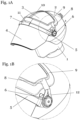
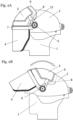
- FIGS. 1A, 1B , 2A and 2B show various views of a preferred embodiment of a forehead shield 3 according to the invention on a protective helmet 2.
- the helmet 2 is a ballistic protective helmet, as can typically be worn by emergency services, such as police or other emergency services, to protect themselves from any kind of external gunfire and/or force.
- the exemplary embodiments of the present invention shown here relate to ballistic protective helmets for special forces and police officers, but are not exclusively limited to these, but can also be used, for example, for protective helmets for military use.
- the helmet cap 2 can be made of metal, fiber-reinforced plastic and/or a combination of both (hybrid helmet).
- titanium is used as metal and aramid and/or polyethylene fibers are used as fiber-reinforced plastic.
- the helmet cap 2 can be produced in a deep-drawing process, preferably from a one-piece titanium sheet, with a single- or multi-layer structure of the cap being possible. It is also possible to make the helmet from steel or aluminum.
- one or more layers made of preferably a fiber composite material made of high molecular weight polyethylene fibers (UHMW-PE) are optionally possible, but are not limited to these. Further layers of aramid fibers can be added to this.
- UHMW-PE high molecular weight polyethylene fibers
- aramid fibers can be added to this.
- other fiber composites can also be considered.
- a combination of materials is referred to as a hybrid.
- the helmet cap 2 can also be made entirely of plastics and/or fiber-rein
- a forehead shield 3 is attached to the ballistic protective helmet 2, which can be worn in combination with a visor 4 (e.g. visual visor).
- the front shield 3 or the actual ballistic element of the front shield is preferably manufactured in such a way that it meets certain requirements of the VPAM (Association of Testing authorities for Attack-Resistant Materials and Construction) testing guidelines, but is not limited to them.
- VPAM Association of Testing authorities for Attack-Resistant Materials and Construction
- the end shield 3 is made of a fiber composite material made of high molecular weight polyethylene fibers (Ultra High Molecular Weight Polyethylene, UHMW-PE), but can in principle also be made of other materials, such as titanium, aluminum, steel or fiber-reinforced plastic, for example made of aramid fibers .
- UHMW-PE Ultra High Molecular Weight Polyethylene
- the front shield or the actual ballistic element 3 is accommodated in a housing 9, which can, for example, have a rubber edging band and, with an additional rubber band 10, prevents the front shield or the ballistic element 3 from slipping or falling out.
- a tensioning element 8 which can be set up, for example, as a rubber band with a tab.
- the enclosure 9 in another embodiment, as can be achieved, for example, by a pocket-like enclosure, which The front shield or the ballistic element 3 can be completely or only partially enclosed and thus encased.
- the enclosure itself can, in addition to a rubber edging, also have other constructions such as a textile element.
- a metallic embodiment of the housing for example as a bent sheet metal part, is also conceivable, in which the end shield is fastened, for example by means of snap fasteners or a clip connection, with the possibility of the embodiments not being limited to the embodiments mentioned.
- the housing 9 and thus the forehead shield accommodated therein or the actual ballistic element 3 is movable along the surface of the helmet cap 2 so that a visor 4 attached to the helmet 2 can be moved up and down.
- the visor 4 is set up as an all-plastic visor (visual visor) according to VPAM2/VPAM3, although other types of visor can also be used with the disclosure according to the invention.
- the visor 4 can also be held by a visor bracket 5 and thus connected to the rest of the protective helmet 2.
- the visor bracket 5 can be rotatably connected to the protective helmet. This can be achieved by attaching corresponding bearings 6 (e.g.
- visor bearings laterally, on both sides of the protective helmet, around which the visor bracket 5 can be rotatably attached/mounted.
- the bearings 6 are preferably attached to the helmet 2 in such a way that they are realized on opposite sides.
- the present invention is not limited to this form of attachment.
- the bearing 6 offers at least one locking point, so that the visor bracket 5 can assume different angles relative to the vertical axis of the wearer. This offers the particular advantage that the visor 4 can be opened and the open visor position can be locked and thus an unwanted folding down of the visor, for example when the wearer is running, can be prevented. Likewise, in a preferred embodiment, at least one further latching point is provided, which stabilizes the closed state of the visor 4. Possible embodiments of the locking points are not those described above Configurations are limited, but any additional locking points can be integrated into the warehouse 6.
- visor bracket and thus the visor 4
- housing 9 and thus the front shield or the ballistic element 3
- Velcro application 7 it is possible to connect the visor bracket (and thus the visor 4) to the housing 9 (and thus the front shield or the ballistic element 3) by means of a Velcro application 7, although other fastening mechanisms are also possible possible are.
- the visor bracket 5 is rotated around the bearing 6, the visor 4 can be folded up or down, with the front shield 3 moving with the visor 4 due to the Velcro application 7, as the front shield 3 slides on the surface of the helmet 2.
- one or more of the helmet components helmet 2, protective shield or ballistic element 3, visor 4, visor bar 5, bearing 6, Velcro applications 7, tensioning element 8, housing 9, and / or rubber band 10 can be made of one or more Several flame-retardant materials can be made, such as leather, Nomex, Kermel, rubber, flame-retardant plastics according to UL94 V-0 and metals, in order to be able to increase the protective effect of the helmet accordingly.
- the Velcro application 7 between the visor bracket 5 and the housing 9 can be arranged in such a way that a kind of hinge 11 results, which makes it possible to create an angle between the housing 9 and the visor bracket 5 (and the visor 4 connected to it). to set.
- the direction of rotation of the visor 4 can be from the head 1 of a wearer outwards (and vice versa).
- the protective helmet 2 can also be worn without a visor within the scope of the present invention.
- static designs are also conceivable, in which the front shield 3 is connected to the helmet cap 2, for example by a further Velcro application 13.
- the front shield 3 can also be used as a retrofit item for an existing protective helmet, which has all the fastening elements required to hold the front shield, but can also be used in combination with a protective helmet as one Type of unit can be purchased.
- the use of the front shield is possible both with an enclosure 9 and without an enclosure 9, although it is also possible here to retrofit a protective helmet with an enclosure to accommodate a protective shield.
- the protective helmet in combination with a movable forehead shield according to the invention (with or without housing), can also be combined with a visor 4 (eg a visual visor), whereby the visor 4 can also be designed as an optional additional retrofit option.
- the retrofitted visor can also be set up to be movable as a unit on the surface of the helmet cap with a retrofitted front shield (with and without housing).
- the at least one clamping element 8 fulfills two relevant functions: On the one hand, the tensioning element ensures that the housing 9 is pressed against the helmet cap 2. Furthermore, the at least one tensioning element 8 serves to enable a joint movement of the housing and visor over the helmet cap, with the housing being lifted off at its lower edge during the movement over the helmet cap surface, due to its non-spherical shape.
- An elastic and tensionable material can, for example, be realized relatively easily using an elastic band or an elastic textile, for example based on elastane.
- the clamping element is designed in such a way that it has a loop-shaped structure 12 at at least one end, which can be used to hang it on at least one bearing and thus, due to the clamping force, the end shield with or without housing against the Press the helmet cap.
- Fig. 3A shows a side view of a ballistic protective helmet 2 in a further unclaimed embodiment, in which the helmet 2 can be worn without a visor and the associated visor bar.
- the front shield or its ballistic element 3 is also introduced into an enclosure 9 and received by it.
- the enclosure 9 is held in position by means of a loop 13, which is attached to the top of the helmet 2 (preferably by an adhesive connection), and via a fastening element 14 attached to the loop 13 in the form of a Velcro pad.
- the Fastening element 14, which can be connected to the housing 9 via a band, for example, protects the housing 9 from unintentional movement, such as slipping or falling.
- the ballistic element 3 of the front shield can additionally be connected to the housing 9 by a further fastening element 14, thereby preventing the ballistic element 3 from slipping or falling out of the housing 9.
- this holding function is taken over by the Velcro application 7.
- an additional Velcro application 16 which in a preferred embodiment is designed to be folded out, it is possible to establish an additional connection between the helmet 2 and the housing 9.
- the Velcro fleece application 7 is connected to the Velcro fleece application 16. This serves to prevent the housing 9 from unintentionally lifting off and/or slipping from the helmet 2.
- Fig. 3B shows a front view of the ballistic protective helmet 2 of the further unclaimed embodiment Fig. 3A , in which the protective helmet 2 is worn without a visor and only the ballistic element 3 of the forehead shield is attached to the helmet 2 in the housing 9 and is additionally held by the further fastening element 10.
- the Velcro applications 7, 14, 15, 16 it is possible to prevent the housing 9 from unintentionally lifting off and/or slipping away.
- FIG. 4 shows an alternative solution for a front shield that can be moved with a visor.
- a rail structure 18 of the front shield is attached to the helmet cap 2, which in a preferred embodiment has a T-groove into which a movable part of the front shield is inserted.
- a corresponding recess 19 in the rail structure 17 enables the T-shaped sliding part 18 to be inserted.
- the movable part of the front shield in particular its ballistic element, can thus be pulled forward via the rail structure 17 to the visor bracket 5, to which the visor 4 is attached, and can be connected to it using the Velcro application 7.
- This rail structure 17 also allows the end shield 3 to move along the surface of the helmet cap 2.
- This alternative solution can also be used both with and without a visor.
- the rail structure can be connected to the helmet cap either permanently (e.g. by direct gluing) or removably. If the guide rail is attached to the helmet cap in a removable manner, it can be placed in an unused position
- Embodiment a Velcro application can be used for temporary attachment.
- a stop for the T-shaped sliding part 18 can be provided, which serves in particular to prevent the head shield from unintentionally slipping when the protective helmet 2 is worn without a visor.
- the Velcro fleece applications 7 and 16 can be used for fixation.
- a flexibly configured pair of guide rails which can be attached to the helmet cap both permanently and removably, can also be used to movably mount the forehead shield.
- Plastics, flame-retardant plastics and/or impact-modified plastics according to UL94 V-0 as well as metals are particularly suitable for assembly.
Landscapes
- Engineering & Computer Science (AREA)
- General Engineering & Computer Science (AREA)
- Helmets And Other Head Coverings (AREA)
Description
- Die vorliegende Erfindung betrifft ein bewegliches Stirnschild für einen ballistischen Schutzhelm.
- Ballistische Schutzhelme zum Schutz des Kopfes seines Trägers sind im Stand der Technik bereits seit längerem bekannt. Diese dienen zum Schutz vor direkter Krafteinwirkung durch z.B. Beschuss mit Feuerwaffen oder indirekt unter anderem durch die Einwirkung auf den Kopf des Trägers durch Splitter sowie durch die Einwirkung von Hieb- und Stichwaffen. Typischerweise wird diese Art von Helmen durch Spezialeinsatzkräfte und zunehmend auch von Streifenpolizisten getragen, welche zuerst am Einsatzort eintreffen (sogenannte "First Responder") mit der Zielsetzung des Eigenschutzes des Trägers.
- Die Schutzwirkung eines derartigen Helms wird dadurch erreicht, dass ein auftreffendes Projektil (oder Splitter) gestoppt wird und somit eine Penetration des Helmes hin zum Kopf des Trägers verhindert wird. Insbesondere soll dabei die kinetische Energie der auftreffenden Teile minimiert werden, um so den Träger vor letalen Auswirkungen zu schützen. Als typische Materialen, aus denen die Helmkalotte eines ballistischen Schutzhelms gefertigt ist, können Titan, Aramid oder Polyethylen in Betracht gezogen werden.
- Zum weiteren Schutz des Gesichts, sowie insbesondere der Augen des Trägers ist es möglich, den Helm mit einem Sichtvisier auszustatten, welches sowohl permanent vor dem Gesicht als auch auf- und herunterklappbar eingerichtet sein kann.
- Um vor allem den anatomisch empfindlichen Stirnbereich des Trägers bei einer frontalen Konfrontation, z.B. bei frontalem Beschuss, aber auch bei einem Angriff mittels Hieb-, Stich- oder Schlagwaffen zusätzlich zu schützen, besteht die Möglichkeit, ballistische Schutzhelme mit einem Schild bzw. einem Stirnschild zu erweitern, um dadurch eine weitere, verstärkte Schutzzone im Bereich der Stirn des Trägers zu erhalten. Es hat sich nämlich gezeigt, dass sehr häufig Angriffe auf Polizisten und Einsatzkräfte von vorne ausgeübt werden.
- Typischerweise wird das Stirnschild an der Helmkalotte über eine Klett-Flausch-Applikation angebracht, siehe z.B.
EP 3 520 641 A1 . Diese Anbringungsweise führt dazu, dass der Schild lösbar an der Helmkalotte angebracht werden kann, um so die Schutzwirkung des ballistischen Helms situativ ergänzen zu können (ggfs. in Zusammenwirkung mit einem Visier). Situative Gegebenheiten umfassen dabei z.B. einen erwarteten Beschuss mit einer Langwaffe oder sonstige frontale Einwirkungen, deren sich der Träger des Schilds direkter zuwenden kann. Ist die Bedrohungslage als geringer einzustufen, kann der Schild zur Gewichtsreduktion des Helms abgenommen werden und damit der Tragekomfort für den Träger erhöht werden. - Die Verwendung eines zusätzlichen Schilds führt jedoch regelmäßig zu Nachteilen, wenn der Helm zusammen mit einem Stirnschild und einem Visier verwendet werden soll. Durch die räumliche Ausdehnung des Stirnschilds, ist es bei einem herkömmlichen Visier nicht mehr möglich, dieses zu öffnen (z.B. durch Hochklappen), da dies durch die räumliche Ausdehnung des Stirnschilds verhindert wird. Diese Problematik kann dadurch umgangen werden, dass das Visier derart konstruiert wird, dass es in der Lage ist, über das Stirnschild zu gleiten. Auf Grund des Eigengewichts des Visiers und dem nun verlängerten Hebelarm, erhöht sich das auf den Helm einwirkende Drehmoment was zu einer Beeinträchtigung des Tragekomforts führt.
- ITUB20160865 offenbart auch einen Stirnschild für einen ballistischen Schuzthelm.
- Der Erfindung liegt daher die Aufgabe zugrunde, die aus dem Stand der Technik bekannte Ausgestaltung der Stirnschilde dahingehend zu verbessern, dass diese auch in Kombination mit einem Visier verwendet werden können, ohne die aus dem Stand der Technik bekannten Beeinträchtigungen des Tragekomforts und ohne die Sicherheit der Polizisten oder Einsatzkräfte durch die Einrichtungsweise zu beeinträchtigen oder zu gefährden.
- Diese Aufgabe wird gelöst durch ein Stirnschild für einen ballistischen Schutzhelm, welches eingerichtet ist, sich beim Öffnen und Schließen eines Visiers des Schutzhelms mit dem Visier mitzubewegen. Erfindungsgemäß wird das Stirnschild so an dem Helm befestigt, dass sich ein Visier zusammen mit dem Stirnschild bewegen lässt. Hierzu kann das Stirnschild grundsätzlich verschiebbar an dem Helm angebracht sein. Dies bietet den Vorteil, dass auf diese Weise ein herkömmliches Visier verwendet werden kann, welches somit den bereits bekannten Tragekomfort bietet. Auf ein über das Stirnschild gleitendes Visier kann verzichtet werden. Außerdem ist ein aufwändiges Umrüsten des Helms situativ nicht mehr erforderlich, da die gewünschte Funktionalität des Öffnens und Schließens (bzw. Hoch- und Herunterklappen) des Visiers auch in gemeinsamer Verwendung mit dem Stirnschild ermöglicht wird.
- In der vorliegenden Offenbarung werden mehrere alternative Möglichkeiten beschrieben, wie das Stirnschild verschiebbar an einem Schutzhelm befestigt werden kann. Der Begriff "verschiebbar" schließt dabei nicht aus, dass das Stirnschild oder ein Teil davon zusätzlich zu einer Bewegung relativ zur Oberfläche einer Helmkalotte auch eine Rotation vollführt, wenn das Stirnschild oder ein Teil davon durch ein Visier des Schutzhelms bewegt wird. Beispielsweise kann das Stirnschild oder ein Teil davon, an der Unterkante von der Helmoberfläche abgehoben werden während sich das Visier nach oben, also aus dem Sichtfeld, bewegt. Zusätzlich zur Verschiebebewegung findet dann also eine Rotation statt. Dies ist jedoch durch den Begriff "verschiebbar" nicht ausgeschlossen.
- Grundsätzlich aufweist das Stirnschild hierzu eine Vorrichtung, um das Stirnschild abnehmbar und verschiebbar an dem Schutzhelm anzubringen. Dies bietet dem Träger des Schutzhelms die Möglichkeit, sich situativ an die jeweiligen Einsatzbedingungen anzupassen und bei einer erhöhten Gefährdungslage auf einen zusätzlichen ballistischen Schutz, welcher durch das Stirnschild ermöglicht werden kann, entsprechend zurückgreifen zu können. Ein abnehmbares Stirnschild bietet auch die Möglichkeit, bereits existierende Helme um ein Stirnschild erweitern bzw. nachrüsten zu können. Als Befestigungsmöglichkeit werden bevorzugt z.B. Klett-Flausch-Applikationen verwendet.
- Eine Möglichkeit, die oben genannte Vorrichtung auszubilden, besteht in einer Einhausung, welche Mittel zum Anpressen des Stirnschilds gegen eine Außenseite einer Helmkalotte des Schutzhelms aufweist. Die Einhausung kann eingerichtet sein, einen ballistischen Teil des Stirnschilds aufzunehmen. Darunter ist jener Teil des Stirnschilds zu verstehen, welchem die eigentliche Schutzwirkung zukommt, z.B. bei Beschuss oder der Einwirkung durch Hieb- und Stichwaffen, und welcher aus einem ausreichend widerstandsfähigen Material, z.B. Titan oder einem Faserverbundstoff gefertigt sein kann. Grundsätzlich wird im Rahmen der vorliegenden Erfindung unter einem Stirnschild also je nach Kontext nicht nur dieser eigentliche ballistische Teil verstanden, sondern auch weitere Mittel, Vorrichtungen und Elemente, welche z.B. zur Befestigung des ballistischen Teils an einem Schutzhelm oder der Verbindung mit einem Visier dienen. Ziel der Einhausung ist es, das Stirnschild beweglich, aber dennoch ausreichend fest und stabil am Helm zu befestigen. Bei der Einhausung kann es sich z.B. um eine Tasche handeln, welche eingerichtet ist, den ballistischen Teil des Stirnschilds aufzunehmen und entlang der Oberfläche der Helmkalotte zu gleiten. Alternativ kann es sich um eine Einfassung handeln, welche zumindest einen Teil des Rands des ballistischen Teils einfasst.
- Da der ballistische Teil des Stirnschilds in einer Einhausung untergebracht wird, sind zudem keine mechanischen Bearbeitungen des ballistischen Teils notwendig, welche der Schutzwirkung des Stirnschilds abträglich sein könnten. Grundsätzlich verringern nämlich mechanische Bearbeitungen des ballistischen Teils des Stirnschilds, wie zum Beispiel Bohrlöcher, dessen Schutzwirkung.
- Die Einhausung weist zudem Mittel zum Anpressen des Stirnschilds gegen eine Außenseite einer Helmkalotte des Schutzhelms auf. Hierdurch wird einerseits das Stirnschild ausreichend fest an der Helmkalotte gehalten. Andererseits wird gewährleistet, dass sich zumindest ein Teil des Stirnschilds beim Öffnen des Visiers ausreichend von der Helmkalotte abheben kann. Ein derartiges Abheben kann dadurch zustande kommen, dass das Stirnschild an einem Visier befestigt wird und dieses beim Öffnen einen sich vergrößernden Abstand zur Helmkalotte aufgrund deren nicht-sphärischer Form und/oder einer exzentrischen Anordnung der Visierlager bildet. Das oder die Mittel zum Anpressen des Stirnschilds gleichen diese durch das Visier verursachte Abhebebewegung entsprechend aus.
- Die Einhausung ist dazu eingerichtet, abnehmbar mit einer Helmkalotte verbunden zu werden. Dadurch kann die Einhausung bei Bedarf mit dem Helm verbunden und dieser somit mit einem Stirnschild getragen werden.
- Die Einhausung ist so eingerichtet, dass sie eine Verbindung mit einem Visier ermöglicht und von diesem abnehmbar eingerichtet ist. Die Einhausung kann so eingerichtet sein, dass sie eine Befestigung an der Helmkalotte und/oder des Visiers ermöglicht. Die Befestigungsmöglichkeit ist dabei bevorzugt durch eine Klett-Flausch-Applikation ausgebildet.
- Bei dem Mittel zum Anpressen des Stirnschilds gegen eine Außenseite einer Helmkalotte des Schutzhelms kann es sich um zumindest ein Spannelement handeln, welches eingerichtet ist, an zumindest einem Visierlager des Schutzhelms befestigt zu werden. Das Spannelement kann dabei elastisch, z.B. als Gummiband ausgeprägt sein und an zumindest einem Ende eine Schlaufe aufweisen, welche derart beschaffen ist, um an einem Visierlager einer Helmkalotte angebracht zu werden.
- Das Spannelement kann lösbar mit der Einhausung verbunden sein. Beispielsweise kann das Spannelement mittels einer Klett-Flausch-Applikation an der Einhausung verbunden sein. Auf diese Weise lässt sich das Spannelement von der Einhausung trennen und die Einhausung auch ohne Spannelement am Schutzhelm, z.B. mittels einem der Klett-Flausch-Applikation entsprechenden Gegenstück befestigt werden. Hierdurch wird das Stirnschild am Schutzhelm fixiert und lässt sich nicht verschieben. Dies kann z.B. dann gewünscht sein, wenn der Schutzhelm ohne Visier getragen wird.
- Das Spannelement kann näher an einer einem Visier des Schutzhelms abgewandten Seite der Einhausung befestigt sein, als an einer dem Visier zugewandten Seite der Einhausung. Diese Anordnung ermöglicht die bereits erwähnte Abhebe- oder Rotationsbewegung, wenn die Einhausung durch ein Visier des Schutzhelms verschoben wird: Aufgrund der nicht-sphärischen Form des Schutzhelms und/oder einer exzentrischen Position der Visierlager, kommt es an der Unterkante der Einhausung, an welcher das Visier anliegt, zu einer Abhebebewegung bzw. Rotation der Einhausung. Dieser kann dadurch Rechnung getragen werden, dass das Spannelement von der Unterkante der Einhausung weiter entfernt befestigt wird als von deren Oberkante.
- Die Einhausung kann aus zumindest einem flammhemmenden Material gefertigt sein. Auf diese Weise kann ein Abbrennen der Einhausung und/oder des Spannelements bei Beschuss verhindert oder zumindest soweit verzögert werden, dass das Stirnschild auch bei nachfolgendem Beschuss sicher in Position gehalten wird.
- Grundsätzlich kann das erfindungsgemäße Stirnschild mehr als ein Spannelement aufweisen, z.B. zwei Spannelemente, welche an gegenüberliegenden Seiten des Stirnschilds bzw. dessen ballistischen Teils angeordnet sind.
- Wie zuvor bereits erläutert, schlagen die Erfinder mehrere Alternativlösungen für eine verschiebbare Befestigung des erfindungsgemäßen Stirnschilds an einer Helmkalotte vor. Gemäß einer weiteren Alternative handelt es sich bei der Vorrichtung, um das Stirnschild abnehmbar und verschiebbar an dem Schutzhelm anzubringen, um zumindest eine Schiene, welche eingerichtet ist, an dem Schutzhelm befestigt zu werden und einen Teil des Schutzschilds verschiebbar zu halten. Die Schiene kann beispielsweise auf die Helmoberfläche aufgeklebt werden oder an dieser mittels einer Klett-Flausch-Applikation befestigt werden. Der andere Teil des Stirnschilds, insbesondere der ballistische Teil, wird dann durch die Schiene verschiebbar am Schutzhelm gehalten und - ähnlich dem bereits zuvor beschriebenen Einhausungsmechanismus - durch ein Visier des Schutzhelms beim Öffnen und Schließen verschoben.
- Der verschiebbare Teil des Schutzschilds kann ein Gleitelement aufweisen, welches eingerichtet ist um in der Schiene, die vorzugsweise eine T-Nut aufweist, zu gleiten.. Das Gleitelement kann näher an einer dem Visier abgewandten Seite des ballistischen Teils des Stirnschilds angeordnet sein als an einer dem Visier zugewandten Seite. Auf diese Weise kann es auch bei dem hier beschriebenen Schienenmechanismus zu der bereits erwähnten Abhebe- bzw. Rotationsbewegung des beweglichen Teils des Stirnschilds kommen, wenn das Visier geöffnet wird.
- Das Gleitelement und die Schiene können so ausgestaltet sein, dass das Gleitteil in die Schiene eingeführt werden kann. Auf diese Weise kann der bewegliche Teil des Stirnschilds, insbesondere das ballistische Element, lösbar und verschiebbar mit der Helmkalotte verbunden werden.
- Unabhängig vom Befestigungsmechanismus des Stirnschilds an der Helmkalotte, kann das Stirnschild weiter zumindest ein Visierbefestigungsmittel aufweisen, um das Stirnschild mit einem Visier des Schutzhelms zu verbinden. Das Visierbefestigungsmittel kann also sowohl bei der hierin beschriebenen Einhausungslösung als auch bei der Schienenlösung vorhanden sein. Bei der Einhausungslösung kann das Visierbefestigungsmittel an der Einhausung angebracht sein. Das Visierbefestigungsmittel kann als Klett-Flausch-Applikation ausgeführt sein. Ein Teil dieser Applikation kann am Visier, z.B. an einem Visierbügel, und das entsprechende Gegenstück am Stirnschild angeordnet sein. Das Visierbefestigungsmittel kann so eingerichtet sein, dass eine relative Drehung zwischen dem Visier und dem Stirnschild möglich ist. Somit kann die bereits beschriebene Abhebe- oder Rotationsbewegung des Stirnschilds beim Öffnen des Visiers unterstützt werden.
- Das Stirnschild kann grundsätzlich ein Fixierungsmittel aufweisen, um das Stirnschild an dem Schutzhelm zu fixieren. Auf diese Weise kann der Schutzhelm mit dem Stirnschild, jedoch ohne Visier getragen werden. Auch ohne Visier wird auf diese Weise ein Abheben oder Verrutschen des Stirnschilds durch das Fixierungsmittel verhindert.
- Bei dem Visierbefestigungsmittel und/oder bei dem Fixierungsmittel kann es sich um eine Klett-Flausch-Applikation handeln. Dies ermöglicht ein einfaches Umrüsten des Helms zwischen einer Verwendung mit Visier und einer Verwendung ohne Visier: Wenn der Schutzhelm ohne Visier getragen wird, kann das Stirnschild durch die Klett-Flausch-Applikation einfach fixiert werden. Sobald der Schutzhelm wieder mit einem Visier ausgestattet wird, kann die Klett-Flausch-Applikation zwischen Stirnschild und Schutzhelm gelöst und das Stirnschild mittels einer weiteren Klett-Flausch-Applikation am Visier, z.B. an dessen Visierbügel, befestigt werden, um ein Mitbewegen des Stirnschilds mit dem Visier zu ermöglichen, wie hierin beschrieben.
- Ein weiterer Aspekt der vorliegenden Erfindung betrifft einen Schutzhelm, aufweisend (a) eine Helmkalotte; und (b) ein Stirnschild, wie es hierein beschrieben ist.
- Der Schutzhelm kann weiter zumindest ein mit dem Fixierungsmittel des Stirnschilds zusammenwirkendes Mittel aufweisen. Beispielsweise kann es sich dabei um eine Klett-Flausch-Applikation handeln, wobei der Klett-Teil oder der Flauschteil z.B. auf der Oberseite des Helms angeordnet sein kann. Das Stirnschild kann dann, wie zuvor beschrieben, ausreichend fixiert werden, wenn der Schutzhelm ohne Visier getragen wird.
- Das Fixierungsmittel kann ausklappbar ausgestaltet sein. Auf diese Weise ist das Fixierungsmittel beim Tragen des Schutzhelms mit Visier möglichst unauffällig.
- Der Schutzhelm kann ein Visier aufweisen. Wie bereits beschrieben, kann die vorliegende Erfindung besonders vorteilhaft bei einem Schutzhelm mit Visier verwendet werden, da sich das Stirnschild mit dem Visier beim Öffnen und Schließen mitbewegt.
- Das Spannelement kann durch ein elastisches und spannbares Material ausgebildet sein. Auf diese Weise kann das Stirnschild einerseits einfach gegen die Helmoberfläche gepresst werden und liegt somit eng am Helm andererseits erlaubt es durch seine Flexibilität das Abheben des Stirnschildes an der Vorderkante beim Öffnen des Visiers
Noch ein weiterer Aspekt der vorliegenden Erfindung betrifft eine Einhausung für ein ballistisches Element eines Stirnschilds für einen ballistischen Schutzhelm, wobei die Einhausung eingerichtet ist, das ballistische Element aufzunehmen und ein Mittel zum Anpressen des ballistischen Elements gegen eine Außenseite einer Helmkalotte des Schutzhelms aufweist, so dass das ballistische Element abnehmbar und verschiebbar an der Helmkalotte befestigt werden kann. Die Vorteile und weiteren Austgestaltungen einer derartigen Einhausung wurden bereits ausführlich beschrieben, so dass an dieser Stelle zur Vermeidung von Wiederholungen darauf verwiesen wird. - Grundsätzlich kann im Rahmen der vorliegenden Erfindung die Helmkalotte aus Metall, aus faserverstärktem Kunststoff und/oder aus einer Kombination von beiden (Hybrid-Helm) gefertigt sein. Als Metall werden z.B. Titan und als faserverstärkter Kunststoff z.B. Aramid- und/oder Polyethylenfasern verwendet. Ein Hybrid-Helm hat sich vor allem bei Beschuss aus großkalibrigen Waffen als widerstandsfähig erwiesen.
- Die Erfindung ermöglicht insbesondere auch die Nachrüstung von Helmen um ein zusätzliches Stirnschild, wobei der Schutzhelm mit oder ohne Visier getragen werden kann.
- Die Aspekte der vorliegenden Erfindung werden im Folgenden anhand von bevorzugten Ausführungsbeispiele der Erfindung unter Bezugnahme auf die Zeichnungen erläutert. Die Zeichnungen zeigen:
- Fig. 1A:
- Einen erfindungsgemäßen Helm mit einer erfindungsgemäßen Einhausung, einem Stirnschild und einem Visier;
- Fig. 1B:
- Detaildarstellung des Helms aus
Fig. 1A ; - Fig. 2A:
- Seitenansicht des Ausführungsbeispiels aus
Fig. 1A mit Visier im geschlossenen Zustand; - Fig. 2B:
- Seitenansicht des Ausführungsbeispiels aus
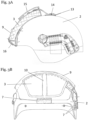
Fig. 1A mit Visier im geöffneten Zustand; und - Fig. 3A:
- eine Seitenansicht eines ballistischen Schutzhelms in einer weiteren bevorzugten Ausführungsform ohne Visier mit angebrachtem Stirnschild; und
- Fig. 3B:
- Frontansicht des ballistischen Schutzhelms aus
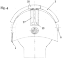
Fig. 3A . - Fig. 4:
- Rückansicht der Helmkalotte mit Schienenstruktur zur Aufnahme eines Stirnschilds und/oder einer Einhausung
- Die
Figuren 1A, 1B ,2A und 2B zeigen verschiedene Ansichten einer bevorzugten Ausführungsform eines erfindungsgemäßen Stirnschilds 3 an einem Schutzhelm 2. Dabei handelt sich um eine von mehreren Möglichkeiten, um das Stirnschild 3 verschiebbar an dem Schutzhelm 2 zu befestigen, nämlich mittels einer Einhausung 9. Bei dem Helm 2 handelt es sich um einen ballistischen Schutzhelm, wie dieser typischerweise von Einsatzkräften, wie z.B. Polizei oder anderen Einsatzkräften getragen werden kann, um sich vor Schuss- und/oder Krafteinwirkungen jeglicher Art von außen zu schützen. Die hier gezeigten Ausführungsbeispiele der vorliegenden Erfindung betreffen ballistische Schutzhelme für Spezialkräfte und Polizisten, sind jedoch nicht exklusiv auf diese beschränkt, sondern sind z.B. auch für Schutzhelme für den militärischen Einsatz anwendbar. - Die Helmkalotte 2 kann aus Metall, aus faserverstärktem Kunststoff und/oder aus einer Kombination von beiden (Hybrid-Helm) gefertigt sein. Als Metall werden z.B. Titan und als faserverstärkter Kunststoff z.B. Aramid- und/oder Polyethylenfasern verwendet. Die Helmkalotte 2 kann in einem Tiefziehprozess, vorzugsweise aus einem einstückigen Titanblech hergestellt werden, wobei ein ein- oder mehrschichtiger Aufbau der Kalotte möglich ist. Eine Herstellung des Helms aus Stahl oder Aluminium ist ebenfalls möglich. Ebenso kommen optional eine oder mehrere Schichten aus vorzugsweise einem Faserverbundmaterial aus hochmolekularen Polyethylenfasern (Ultra High Molecular Weight Polyethylene, UHMW-PE) in Betracht, sind jedoch nicht auf diese beschränkt. Weiterführend können diesem, weitere Schichten mit Aramidfasern beigemischt werden. Neben der bevorzugten Ausführungsform kommen grundsätzlich auch noch andere Faserverbundstoffe in Erwägung Eine Materialkombination wird dabei als Hybrid bezeichnet. Die Helmkalotte 2 kann auch vollständig aus Kunststoffen und/oder faserverstärkten Kunststoffen gefertigt sein.
- An dem ballistische Schutzhelm 2 ist ein Stirnschild 3 angebracht, welches in Kombination mit einem Visier 4 (z.B. Sichtvisier) getragen werden kann. Das Stirnschild 3 bzw. das eigentliche ballistische Element des Stirnschilds, ist dabei bevorzugt so gefertigt, dass es bestimmte Anforderungen der VPAM-(Vereinigung der Prüfstellen für angriffshemmende Materialien und Konstruktion) Prüfungsrichtlinie erfüllt, jedoch nicht darauf beschränkt ist. Durch Anbringen des Stirnschilds 3 ist es möglich, die Front- bzw. Stirnpartie des Kopfes 1 eines Trägers des Schutzhelms 2 zusätzlich vor Einwirkungen, die frontal (oder auf die Stirnpartie abzielen) gegen den Träger gerichtet sind, zu schützen, wie dies z.B. durch frontalen Beschuss, aber auch durch den Einsatz von Hieb- und Stichwaffen bei Schlägen notwendig sein kann. Auch andere, nicht genannte Angriffe auf die vom Schild abgedeckte Kopfpartie, können somit ohne schädigende Effekte auf den Träger des Helms, abgewehrt werden. Das Stirnschild 3 ist in der bevorzugten Ausführungsform aus einem Faserverbundmaterial aus hochmolekularen Polyethylenfasern (Ultra High Molecular Weight Polyethylene, UHMW-PE) gefertigt, kann jedoch grundsätzlich auch aus anderen Materialien gefertigt sein, wie z.B. Titan, Aluminium, Stahl oder faserverstärktem Kunststoff z.B. aus Aramidfasern. Mittels des Stirnschilds 3 ist es somit möglich, eine zusätzliche, optionale Schutzwirkung zu gewährleisten, falls dies situativ erforderlich oder gewünscht ist.
- Im Ausführungsbeispiel der
Figuren 1A, 1B ,2A und 2B ist das Stirnschild, bzw. das eigentliche ballistische Element 3 in einer Einhausung 9 aufgenommen, welche z.B. ein Gummieinfassband aufweisen kann und mit einem zusätzlichen Gummiband 10 ein Verrutschen oder Herausfallen des Stirnschilds bzw. des ballistischen Elements 3 verhindert. Um eine unbeabsichtigte Bewegung des Stirnschilds/ballistischen Elements 3 zu verhindern, wird das Stirnschild/ballistisches Element 3 durch ein Spannelement 8, welches z.B. als Gummiband mit einer Lasche eingerichtet sein kann, gegen die Oberfläche des Helms 2 gepresst. - Neben einem Gummieinfassband sowie dem Spannelement 8 ist es auch möglich, die Einhausung 9 in einer anderen Ausführungsform zu realisieren, wie dies z.B. durch eine taschenartige Einhausung erreicht werden kann, welche das Stirnschild bzw. das ballistische Element 3 komplett oder auch nur teilweise umfassen und damit einhausen kann. Die Einhausung selbst kann dabei, neben einem Gummieinfassband, auch andere Konstruktionen aufweisen wie z.B. ein textiles Element. Des Weiteren ist auch eine metallische Ausführungsform der Einhausung, z.B. als Blechbiegeteil denkbar, in welcher das Stirnschild z.B. durch Druckknöpfe oder eine Clip-Verbindung befestigt wird, wobei die Möglichkeit der Ausführungsformen nicht auf die angeführten Ausführungsformen beschränkt sind.
- Wichtig ist, dass im Rahmen der vorliegenden Erfindung die Einhausung 9 und damit das darin aufgenommene Stirnschild bzw. das eigentliche ballistische Element 3 entlang der Oberfläche der Helmkalotte 2 beweglich ist, damit ein an dem Helm 2 befestigtes Visier 4 auf und ab bewegt werden kann. Das Visier 4 ist in einem bevorzugten Ausführungsbeispiel als ein Vollkunststoffvisier (Sichtvisier) gemäß VPAM2/VPAM3 eingerichtet, wobei jedoch auch andere Visiertypen mit der erfindungsgemäßen Offenbarung genutzt werden können. Das Visier 4 kann des Weiteren von einem Visierbügel 5 gehalten und damit mit dem Rest des Schutzhelms 2 verbunden werden. Der Visierbügel 5 kann drehbar mit dem Schutzhelm verbunden werden. Dies kann dadurch erreicht werden, dass lateral, auf beiden Seiten des Schutzhelms entsprechende Lager 6 (z.B. Visierlager) angebracht werden, um welche der Visierbügel 5 drehbar angebracht/gelagert werden kann. Die Lager 6 werden dabei bevorzugt so am Helm 2 angebracht, dass diese auf gegenüberliegenden Seiten realisiert sind. Die vorliegende Erfindung ist jedoch nicht auf diese Anbringungsform beschränkt.
- In einer bevorzugten Ausführungsform bietet das Lager 6 dabei zumindest einen Rastpunkt, sodass der Visierbügel 5 verschiedene Winkel relativ zur vertikalen Achse des Trägers einnehmen kann. Dies bietet insbesondere den Vorteil, dass das Visier 4 geöffnet werden kann und die geöffnete Visierstellung arretiert werden kann und somit ein unerwünschtes Herunterklappen des Visiers, z.B. bei einer Laufbewegung des Trägers verhindert werden kann. Ebenso ist in einer bevorzugten Ausführungsform zumindest ein weiterer Rastpunkt vorgesehen, der den geschlossenen Zustand des Visiers 4 stabilisiert. Mögliche Ausführungsformen der Rastpunkte sind dabei nicht auf die zuvor beschriebenen Konfigurationen beschränkt, sondern es können beliebige weitere Rastpunkte in das Lager 6 integriert werden.
- In einem bevorzugten Ausführungsbeispiel ist es möglich, mittels einer Klett-Flausch-Applikation 7, den Visierbügel (und damit das Visier 4) mit der Einhausung 9 (und damit dem Stirnschild bzw. dem ballistischen Element 3) zu verbinden, wobei jedoch auch andere Befestigungsmechanismen möglich sind. Bei einer Drehung des Visierbügels 5 um das Lager 6 kann somit das Visier 4 hochgeklappt oder runterklappt werden wobei sich durch die Klett-Flausch-Applikation 7 das Stirnschild 3 mit dem Visier 4 mitbewegt indem das Stirnschild 3 auf der Oberfläche des Helms 2 gleitet.
- In einer bevorzugten Ausführungsform können eine oder mehrere der Helmkomponenten Helm 2, Schutzschild bzw. ballistisches Element 3, Visier 4, Visierbügel 5, Lager 6, Klett-Flausch-Applikationen 7, Spannelement 8, Einhausung 9, und/oder Gummiband 10 aus einem oder mehreren flammhemmenden Materialien gefertigt werden, wie z.B. Leder, Nomex, Kermel, Gummi, Flammehemmende Kunststoffe nach UL94 V-0 und Metalle, um die Schutzwirkung des Helms entsprechend erhöhen zu können.
- Die Klett-Flausch-Applikation 7 zwischen Visierbügel 5 und der Einhausung 9, kann so angeordnet sein, dass sich eine Art Scharnier 11 ergibt, welches es ermöglicht, einen Winkel zwischen der Einhausung 9 sowie dem Visierbügel 5 (und dem damit verbundenen Visier 4) einzustellen. Die Rotationsrichtung des Visiers 4 kann dabei vom Kopf 1 eines Trägers ausgehend nach außen (und umgekehrt) sein.
- Der Schutzhelm 2 kann im Rahmen der vorliegenden Erfindung auch ohne Visier getragen werden. Grundsätzlich sind auch statische Auslegungsformen denkbar, in denen das Stirnschild 3 z.B. durch eine weitere Klett-Flausch-Applikation 13 mit der Helmkalotte 2 verbunden wird. Das Stirnschild 3 kann dabei auch als Nachrüstgegenstand bzgl. eines bereits vorhandenen Schutzhelms, welcher alle benötigten Befestigungselementen zur Aufnahme des Stirnschilds aufweist, benutzt werden, kann jedoch auch in Kombination mit einem Schutzhelm als eine Art Einheit erworben werden. Die Benutzung des Stirnschilds ist dabei sowohl mit Einhausung 9 als auch ohne Einhausung 9 möglich, wobei auch hier eine Nachrüstung eines Schutzhelms um eine Einhausung zur Aufnahme eines Schutzschilds möglich ist. Der Schutzhelm, in Kombination mit einem erfindungsgemäßen beweglichen Stirnschilds (mit oder ohne Einhausung), kann dabei zusätzlich mit einem Visier 4 (z.B. einem Sichtvisier) kombiniert werden, wobei auch das Visier 4 als optionale zusätzliche Nachrüstoption ausgeführt sein kann. Erfindungsgemäß kann das nachgerüstete Visier auch mit nachgerüstetem Stirnschild (mit und ohne Einhausung) als Einheit beweglich auf der Oberfläche der Helmkalotte eingerichtet sein.
- Das zumindest eine Spannelement 8 erfüllt dabei zwei relevante Funktionen:
Zum einen sorgt das Spannelement dafür, dass die Einhausung 9 gegen die Helmkalotte 2 gepresst wird. Des Weiteren dient das zumindest eine Spannelement 8 dazu, eine gemeinsame Bewegung von Einhausung und Visier über die Helmkalotte zu ermöglichen, wobei ein Abheben der Einhausung an deren Unterkante während der Bewegung über die Helmkalottenoberfläche, auf Grund deren nicht-sphärischer Form, ermöglicht wird. Ein elastisches und spannbares Material kann beispielsweise relativ einfach durch einen Gummizug oder ein elastisches Textil, z.B. auf Basis von Elastan, realisiert werden. Das Spannelement ist in einer bevorzugten Ausführungsform dabei so beschaffen, dass es an zumindest an einem Ende eine schlaufenförmige Struktur 12 aufweist, welche dazu benutzt werden kann, diese an zumindest einem Lager einzuhängen und damit auf Grund der Spannkraft das Stirnschild mit oder ohne Einhausung gegen die Helmkalotte zu pressen. -
Fig. 3A zeigt eine Seitenansicht eines ballistischen Schutzhelms 2 in einer weiteren nicht beanspruchten Ausführungsform, in welcher der Helm 2 ohne ein Visier sowie den dazugehörigen Visierbügel getragen werden kann. Das Stirnschild bzw. dessen ballistisches Element 3 wird dabei ebenfalls in eine Einhausung 9 eingebracht und von dieser aufgenommen. Mittels eines Flausches 13, welcher an der Oberseite des Helms 2 (bevorzugt durch eine Klebeverbindung) angebracht ist, und über ein am Flausch 13 angebrachtes Befestigungselement 14 in Form eines Klettpads wird die Einhausung 9 in Position gehalten. Das Befestigungselement 14, welches z.B. über ein Band mit der Einhausung 9 verbunden sein kann, schützt dabei die Einhausung 9 vor einer unbeabsichtigten Bewegung, wie z.B. ein Verrutschen oder Herunterfallen. Das ballistische Element 3 des Stirnschilds kann in einer bevorzugten Ausführungsform zusätzlich durch ein weiteres Befestigungselement 14 mit der Einhausung 9 verbunden werden und dadurch ein Verrutschen oder Herausfallen des ballistischen Elements 3 aus der Einhausung 9 verhindert werden. Beim Tragen des Schutzhelms mit Visier 4, wird diese Haltefunktion durch die Klett-Flausch-Applikation 7 übernommen. Über eine zusätzliche Klett-Flausch-Applikation 16, welche in einer bevorzugten Ausführungsform herausklappbar eingerichtet ist, ist es möglich, eine zusätzliche Verbindung zwischen dem Helm 2 und der Einhausung 9 herzustellen. Dazu wird in der bevorzugten Ausführungsform die Klett-Flausch-Applikation 7 mit der Klett-Flausch-Applikation 16 verbunden. Dies dient dazu, ein unbeabsichtigtes Abheben und/oder Verrutschen der Einhausung 9, vom Helm 2 zu verhindern. -
Fig. 3B zeigt eine Frontansicht des ballistischen Schutzhelms 2 der weiteren nicht beanspruchten Ausführungsform ausFig. 3A , in welcher der Schutzhelm 2 ohne ein Visier getragen wird und lediglich das ballistische Element 3 des Stirnschilds in der Einhausung 9 auf dem Helm 2 angebracht wird und zusätzlich durch das weitere Befestigungselement 10 gehalten wird. Mittels der Klett-Flausch-Applikationen 7, 14, 15, 16 ist es möglich, ein unbeabsichtigtes Abheben und/oder Wegrutschen der Einhausung 9 zu verhindern. -
Figur 4 zeigt eine Alternativlösung für ein Stirnschild, welches mit einem Visier mitbewegt werden kann. An der Helmkalotte 2 ist eine Schienenstruktur 18 des Stirnschilds angebracht, welche in einer bevorzugten Ausführungsform eine T-Nut aufweist, in welche ein beweglicher Teil des Stirnschilds eingeführt wird. Eine entsprechende Aussparung 19 der Schienenstruktur 17 ermöglicht das Einbringen des T-förmigen Gleitteils 18. Über die Schienenstruktur 17 kann somit der bewegliche Teil des Stirnschilds, insbesondere dessen ballistisches Element nach vorne zum Visierbügel 5 gezogen werden, an dem das Visier 4 angebracht ist, und mittels der Klett-Flausch-Applikation 7 mit diesem verbunden werden. Diese Schienenstruktur 17 erlaubt ebenfalls eine Bewegung des Stirnschildes 3 entlang der Oberfläche der Helmkalotte 2. Auch diese Alternativlösung kann sowohl mit als auch ohne Visier verwendet werden. Die Schienenstruktur kann dabei sowohl permanent (z.B. durch direkte Verklebung) oder abnehmbar mit der Helmkalotte verbunden sein. Bei einer abnehmbaren Anbringung der Führungsschiene an der Helmkalotte kann in einer nicht beanspruchten - Ausführungsform eine Klett-Flausch-Applikation zur temporären Befestigung benutzt werden. An der Seite der Schienenstruktur 17, welche dem Visierbügel 5 zugewandt ist, kann ein Anschlag für das T-förmige Gleitteil 18 vorgesehen sein, was insbesondere dazu dient, ein unbeabsichtigtes Verrutschen des Stirnschilds zu verhindern, wenn der Schutzhelm 2 ohne Visier getragen wird. Hierzu können die Klett-Flausch-Applikationen 7 und 16 zur Fixierung verwendet werden.
- In einer weiteren Ausführungsform kann auch ein flexibel eingerichtetes Paar von Führungsschienen, welche an der Helmkalotte, sowohl permanent als auch abnehmbar angebracht werden können, dazu eingesetzt werden, das Stirnschild bewegbar zu lagern. Für die Montage kommen dabei insbesondere Kunststoffe, flammhemmende Kunststoffe und/oder schlagzähmodifizierte Kunststoffe nach UL94 V-0 sowie Metalle in Betracht.
-
- 1
- Kopf
- 2
- Helm / Schutzhelm / Helmkalotte
- 3
- Schild/ Stirnschild/ ballistisches Element
- 4
- Visier / Sichtvisier
- 5
- Visierbefestigungsmittel / Visierbügel
- 6
- Lager
- 7
- Klett-Flausch-Applikation
- 8
- Spannelement
- 9
- Einhausung
- 10
- Gummiband
- 11
- Scharnier
- 12
- Schlaufenförmiges Ende des Spannelements
- 13
- Flausch
- 14
- Befestigungselement
- 15
- Befestigungselement
- 16
- Klett-Flausch-Applikation
- 17
- Schienenstruktur
- 18
- T-förmiges Gleitteil
- 19
- Einführöffnung für Gleitteil
Claims (14)
- Stirnschild (3) für einen ballistischen Schutzhelm (2), welches eingerichtet ist, sich beim Öffnen und Schließen eines Visiers (4) des Schutzhelms (2) mit dem Visier (4) mitzubewegen,
dadurch gekennzeichnet, dass
das Stirnschild (3) eine Vorrichtung (9) aufweist, um das Stirnschild (3) abnehmbar und verschiebbar an dem Schutzhelm (2) anzubringen. - Stirnschild (3) nach Anspruch 1, wobei es sich bei der Vorrichtung um eine Einhausung (9) handelt, welche Mittel (8) zum Anpressen des Stirnschilds (3) gegen eine Außenseite einer Helmkalotte des Schutzhelms (2) aufweist.
- Stirnschild (3) nach Anspruch 2, wobei es sich bei dem Mittel um zumindest ein Spannelement (8) handelt, welches eingerichtet ist, an zumindest einem Visierlager (6) des Schutzhelms (2) befestigt zu werden.
- Stirnschild (3) nach Anspruch 3, wobei das Spannelement (8) näher an einer einem Visier (4) des Schutzhelms (2) abgewandten Seite der Einhausung (9) befestigt ist, als an einer dem Visier (4) zugewandten Seite der Einhausung (9).
- Stirnschild (3) nach einem der Ansprüche 2 bis 4, wobei die Einhausung (9) aus zumindest einem flammhemmenden Material gefertigt ist.
- Stirnschild (3) nach Anspruch 1, wobei es sich bei der Vorrichtung um zumindest eine Schiene (17) handelt, welche eingerichtet ist, an dem Schutzhelm (2) befestigt zu werden und einen Teil des Schutzschilds (3) verschiebbar zu halten.
- Stirnschild (3) nach Anspruch 6, wobei der verschiebbare Teil des Schutzschilds (3) ein Gleitelement (18) aufweiset, welches eingerichtet ist, in der Schiene (17) zu gleiten.
- Stirnschild (3) nach einem der Ansprüche 1 bis 7, weiter aufweisend zumindest ein Visierbefestigungsmittel, um das Stirnschild mit einem Visier des Schutzhelms zu verbinden.
- Stirnschild (3) nach einem der Ansprüche 1 bis 8, weiter aufweisend zumindest ein Fixierungsmittel, um das Stirnschild (3) an dem Schutzhelm (2) zu fixieren.
- Stirnschild (3) nach einem der Ansprüche 8 oder 9, wobei es sich bei dem Visierbefestigungsmittel und/oder bei dem Fixierungsmittel um eine Klett-Flausch-Applikation (7) handelt.
- Schutzhelm (2), aufweisend:a) eine Helmkalotte; undb) ein Stirnschild (3) nach einem der Ansprüche 1 bis 10.
- Schutzhelm (2) nach Anspruch 11, weiter aufweisend zumindest ein mit dem Fixierungsmittel (7) des Stirnschilds (3) nach Anspruch 10 zusammenwirkendes Mittel.
- Schutzhelm nach einem der Ansprüche 11 oder 12, weiter aufweisend ein Visier (4).
- Einhausung (9) für ein ballistisches Element eines Stirnschilds (3) für einen ballistischen Schutzhelm (2), wobei die Einhausung (9) eingerichtet ist, das ballistische Element aufzunehmen und ein Mittel (8) zum Anpressen des ballistischen Elements gegen eine Außenseite einer Helmkalotte des Schutzhelms (2) aufweist, so dass das ballistische Element abnehmbar und verschiebbar an der Helmkalotte befestigt werden kann.
Priority Applications (9)
| Application Number | Priority Date | Filing Date | Title |
|---|---|---|---|
| PL20170849.2T PL3900564T3 (pl) | 2020-04-22 | 2020-04-22 | Ruchoma osłona czołowa |
| HRP20240425TT HRP20240425T1 (hr) | 2020-04-22 | 2020-04-22 | Pomični štitnik za čelo |
| EP20170849.2A EP3900564B1 (de) | 2020-04-22 | 2020-04-22 | Bewegliches stirnschild |
| ES20170849T ES2978506T3 (es) | 2020-04-22 | 2020-04-22 | Escudo frontal móvil |
| DE202021001121.8U DE202021001121U1 (de) | 2020-04-22 | 2021-03-24 | Bewegliches Stirnschild |
| IL282346A IL282346B2 (en) | 2020-04-22 | 2021-04-14 | Portable forehead protector |
| US17/235,636 US20210330019A1 (en) | 2020-04-22 | 2021-04-20 | Movable forehead shield |
| AU2021202397A AU2021202397A1 (en) | 2020-04-22 | 2021-04-20 | Movable forehead shield |
| CN202110434507.8A CN113532200A (zh) | 2020-04-22 | 2021-04-22 | 可移动前额护罩 |
Applications Claiming Priority (1)
| Application Number | Priority Date | Filing Date | Title |
|---|---|---|---|
| EP20170849.2A EP3900564B1 (de) | 2020-04-22 | 2020-04-22 | Bewegliches stirnschild |
Publications (2)
| Publication Number | Publication Date |
|---|---|
| EP3900564A1 EP3900564A1 (de) | 2021-10-27 |
| EP3900564B1 true EP3900564B1 (de) | 2023-12-27 |
Family
ID=70464830
Family Applications (1)
| Application Number | Title | Priority Date | Filing Date |
|---|---|---|---|
| EP20170849.2A Active EP3900564B1 (de) | 2020-04-22 | 2020-04-22 | Bewegliches stirnschild |
Country Status (9)
| Country | Link |
|---|---|
| US (1) | US20210330019A1 (de) |
| EP (1) | EP3900564B1 (de) |
| CN (1) | CN113532200A (de) |
| AU (1) | AU2021202397A1 (de) |
| DE (1) | DE202021001121U1 (de) |
| ES (1) | ES2978506T3 (de) |
| HR (1) | HRP20240425T1 (de) |
| IL (1) | IL282346B2 (de) |
| PL (1) | PL3900564T3 (de) |
Families Citing this family (6)
| Publication number | Priority date | Publication date | Assignee | Title |
|---|---|---|---|---|
| EP3981275A1 (de) * | 2020-10-06 | 2022-04-13 | Ulbrichts GmbH | Visier für einen ballistischen schutzhelm |
| US20220386734A1 (en) * | 2021-06-04 | 2022-12-08 | Jordan Hunter | Adjustable looped-cord goggle attachable to a helmet |
| CN114468452A (zh) * | 2022-01-25 | 2022-05-13 | 北京阿拉叮特种装备有限公司 | 一种智能ar面罩 |
| EP4305991A1 (de) * | 2022-07-15 | 2024-01-17 | Ulbrichts GmbH | Helmkalotte für einen schutzhelm |
| US12274323B2 (en) * | 2023-06-20 | 2025-04-15 | Ourad Safety Co., Ltd. | Device for connecting lens and earmuff to safety helmet |
| US20250325053A1 (en) * | 2024-04-18 | 2025-10-23 | Joseph Bryan Guzzardi | Eye protection apparatus |
Family Cites Families (15)
| Publication number | Priority date | Publication date | Assignee | Title |
|---|---|---|---|---|
| DE313012C (de) * | ||||
| US3548411A (en) * | 1969-02-26 | 1970-12-22 | Us Navy | Retractable goggles for helmet |
| US3783452A (en) * | 1972-04-11 | 1974-01-08 | Us Navy | Removable goggles for helmet |
| US5893174A (en) * | 1995-05-22 | 1999-04-13 | Primeau; Charles W. | Non-discard protective facemask/helmet assembly |
| FR2838307B3 (fr) * | 2002-04-16 | 2004-07-09 | Salomon Sa | Ensemble forme par un casque et un masque de protection notamment pour le ski ou la moto |
| CA2658238C (en) * | 2009-03-16 | 2010-05-18 | Danny Higgins | Helmet having a guiding mechanism for a compatible visor and a visor for such a helmet |
| US9222758B2 (en) * | 2011-08-26 | 2015-12-29 | Velocity Systems, Llc | Versatile protective helmet appliqué assembly |
| EP2844098B1 (de) * | 2012-04-30 | 2016-06-22 | Société Anonyme des Ets. CATU | Schutzhelm für mechanische-, elektrische- und wärmebelastung für elektriker |
| WO2015030703A1 (en) * | 2013-08-26 | 2015-03-05 | Velocity Systems Llc | Versatile protective helmet applique assembly |
| WO2016205757A1 (en) * | 2015-06-19 | 2016-12-22 | Oakley, Inc. | Sports helmet having modular components |
| WO2017136936A1 (en) * | 2016-02-10 | 2017-08-17 | Pre Labs Inc. | Ballistic body armor panels and methods of making same |
| ITUB20160865A1 (it) * | 2016-02-18 | 2017-08-18 | Maurizio Castrati | Elmetto con protezione balistica |
| IT201700021390A1 (it) * | 2017-02-24 | 2018-08-24 | Ci Erre E S R L | Casco protettivo con visiera/occhiale ribaltabile. |
| CN111698920A (zh) * | 2018-01-31 | 2020-09-22 | 乌尔布里希特有限责任公司 | 弹道保护头盔 |
| HRP20240759T1 (hr) * | 2018-01-31 | 2024-09-13 | Ulbrichts Gmbh | Balistička zaštitna kaciga |
-
2020
- 2020-04-22 EP EP20170849.2A patent/EP3900564B1/de active Active
- 2020-04-22 ES ES20170849T patent/ES2978506T3/es active Active
- 2020-04-22 PL PL20170849.2T patent/PL3900564T3/pl unknown
- 2020-04-22 HR HRP20240425TT patent/HRP20240425T1/hr unknown
-
2021
- 2021-03-24 DE DE202021001121.8U patent/DE202021001121U1/de not_active Expired - Lifetime
- 2021-04-14 IL IL282346A patent/IL282346B2/en unknown
- 2021-04-20 AU AU2021202397A patent/AU2021202397A1/en not_active Abandoned
- 2021-04-20 US US17/235,636 patent/US20210330019A1/en active Pending
- 2021-04-22 CN CN202110434507.8A patent/CN113532200A/zh active Pending
Also Published As
| Publication number | Publication date |
|---|---|
| ES2978506T3 (es) | 2024-09-13 |
| DE202021001121U1 (de) | 2021-04-01 |
| CN113532200A (zh) | 2021-10-22 |
| IL282346B2 (en) | 2025-04-01 |
| US20210330019A1 (en) | 2021-10-28 |
| HRP20240425T1 (hr) | 2024-06-21 |
| PL3900564T3 (pl) | 2024-06-24 |
| EP3900564A1 (de) | 2021-10-27 |
| AU2021202397A1 (en) | 2021-11-11 |
| IL282346A (en) | 2021-10-31 |
| IL282346B1 (en) | 2024-12-01 |
Similar Documents
| Publication | Publication Date | Title |
|---|---|---|
| EP3900564B1 (de) | Bewegliches stirnschild | |
| DE102009042455B4 (de) | Tragsystem mit einer ballistischen Schutzweste | |
| AT516055B1 (de) | Schutzhelm | |
| DE69814405T2 (de) | Kopfbedeckung mit einer gelenkartigen befestigungsvorrichtung für ein visier | |
| EP1841338B1 (de) | Helm | |
| EP3054801B1 (de) | Schutzhelm | |
| DE102007048106A1 (de) | Schutzweste | |
| DE2442881A1 (de) | Kopfschutz | |
| DE102008021487B4 (de) | Klappwinkelspiegel und Einblickvorrichtung für Klappwinkelspiegel | |
| EP2057910B1 (de) | Schutzhelmsystem | |
| AT1298U1 (de) | Schutzhelm | |
| EP0012334A1 (de) | Tragbarer Schutzschild | |
| DE29605503U1 (de) | Körperschutzpanzerung und Körperschutzweste oder -jacke hierfür | |
| EP1843123A1 (de) | Schutzeinrichtung an einer Ein-/Ausstiegsluke eines Kampffahrzeugs, insbesondere eines Kampfpanzers | |
| WO2019149661A1 (de) | Ballistischer schutzhelm | |
| DE102022132430A1 (de) | Modulares Helmsystem | |
| EP4212050A1 (de) | Innensystem für einen schutzhelm | |
| DE29608345U1 (de) | Helm, insbesondere für den Arbeits-, Brand- und Katastrophenschutz | |
| CH666344A5 (en) | Anti-bullet and splinter helmet for security personnel - has shell with titanium outer layer, inner cover of woven plastic between resilient layers, carrier cage, and titanium visor | |
| DE20318934U1 (de) | Tragbares Schutzschild | |
| DE69823775T2 (de) | Militärischer Schutzhelm | |
| EP3764053B1 (de) | Körperschutzpanzerung mit lösbarem schulterschutz | |
| EP4212049A1 (de) | Aussensystem für einen schutzhelm | |
| EP4602967A1 (de) | Helmkalotte für einen schutzhelm mit verstärkungsschicht | |
| EP3520641A1 (de) | Ballistischer schutzhelm |
Legal Events
| Date | Code | Title | Description |
|---|---|---|---|
| REG | Reference to a national code |
Ref country code: HR Ref legal event code: TUEP Ref document number: P20240425T Country of ref document: HR |
|
| PUAI | Public reference made under article 153(3) epc to a published international application that has entered the european phase |
Free format text: ORIGINAL CODE: 0009012 |
|
| STAA | Information on the status of an ep patent application or granted ep patent |
Free format text: STATUS: THE APPLICATION HAS BEEN PUBLISHED |
|
| AK | Designated contracting states |
Kind code of ref document: A1 Designated state(s): AL AT BE BG CH CY CZ DE DK EE ES FI FR GB GR HR HU IE IS IT LI LT LU LV MC MK MT NL NO PL PT RO RS SE SI SK SM TR |
|
| B565 | Issuance of search results under rule 164(2) epc |
Effective date: 20200915 |
|
| STAA | Information on the status of an ep patent application or granted ep patent |
Free format text: STATUS: REQUEST FOR EXAMINATION WAS MADE |
|
| 17P | Request for examination filed |
Effective date: 20220427 |
|
| RBV | Designated contracting states (corrected) |
Designated state(s): AL AT BE BG CH CY CZ DE DK EE ES FI FR GB GR HR HU IE IS IT LI LT LU LV MC MK MT NL NO PL PT RO RS SE SI SK SM TR |
|
| RIC1 | Information provided on ipc code assigned before grant |
Ipc: F41H 1/08 20060101ALI20230512BHEP Ipc: F41H 1/06 20060101ALI20230512BHEP Ipc: A42B 3/18 20060101AFI20230512BHEP |
|
| GRAP | Despatch of communication of intention to grant a patent |
Free format text: ORIGINAL CODE: EPIDOSNIGR1 |
|
| STAA | Information on the status of an ep patent application or granted ep patent |
Free format text: STATUS: GRANT OF PATENT IS INTENDED |
|
| INTG | Intention to grant announced |
Effective date: 20230707 |
|
| GRAS | Grant fee paid |
Free format text: ORIGINAL CODE: EPIDOSNIGR3 |
|
| GRAA | (expected) grant |
Free format text: ORIGINAL CODE: 0009210 |
|
| STAA | Information on the status of an ep patent application or granted ep patent |
Free format text: STATUS: THE PATENT HAS BEEN GRANTED |
|
| AK | Designated contracting states |
Kind code of ref document: B1 Designated state(s): AL AT BE BG CH CY CZ DE DK EE ES FI FR GB GR HR HU IE IS IT LI LT LU LV MC MK MT NL NO PL PT RO RS SE SI SK SM TR |
|
| REG | Reference to a national code |
Ref country code: GB Ref legal event code: FG4D Free format text: NOT ENGLISH |
|
| REG | Reference to a national code |
Ref country code: CH Ref legal event code: EP |
|
| REG | Reference to a national code |
Ref country code: DE Ref legal event code: R096 Ref document number: 502020006486 Country of ref document: DE |
|
| REG | Reference to a national code |
Ref country code: IE Ref legal event code: FG4D Free format text: LANGUAGE OF EP DOCUMENT: GERMAN |
|
| PG25 | Lapsed in a contracting state [announced via postgrant information from national office to epo] |
Ref country code: GR Free format text: LAPSE BECAUSE OF FAILURE TO SUBMIT A TRANSLATION OF THE DESCRIPTION OR TO PAY THE FEE WITHIN THE PRESCRIBED TIME-LIMIT Effective date: 20240328 |
|
| REG | Reference to a national code |
Ref country code: LT Ref legal event code: MG9D |
|
| PG25 | Lapsed in a contracting state [announced via postgrant information from national office to epo] |
Ref country code: LT Free format text: LAPSE BECAUSE OF FAILURE TO SUBMIT A TRANSLATION OF THE DESCRIPTION OR TO PAY THE FEE WITHIN THE PRESCRIBED TIME-LIMIT Effective date: 20231227 |
|
| PG25 | Lapsed in a contracting state [announced via postgrant information from national office to epo] |
Ref country code: LT Free format text: LAPSE BECAUSE OF FAILURE TO SUBMIT A TRANSLATION OF THE DESCRIPTION OR TO PAY THE FEE WITHIN THE PRESCRIBED TIME-LIMIT Effective date: 20231227 Ref country code: GR Free format text: LAPSE BECAUSE OF FAILURE TO SUBMIT A TRANSLATION OF THE DESCRIPTION OR TO PAY THE FEE WITHIN THE PRESCRIBED TIME-LIMIT Effective date: 20240328 Ref country code: FI Free format text: LAPSE BECAUSE OF FAILURE TO SUBMIT A TRANSLATION OF THE DESCRIPTION OR TO PAY THE FEE WITHIN THE PRESCRIBED TIME-LIMIT Effective date: 20231227 |
|
| REG | Reference to a national code |
Ref country code: NL Ref legal event code: MP Effective date: 20231227 |
|
| PG25 | Lapsed in a contracting state [announced via postgrant information from national office to epo] |
Ref country code: NL Free format text: LAPSE BECAUSE OF FAILURE TO SUBMIT A TRANSLATION OF THE DESCRIPTION OR TO PAY THE FEE WITHIN THE PRESCRIBED TIME-LIMIT Effective date: 20231227 |
|
| PG25 | Lapsed in a contracting state [announced via postgrant information from national office to epo] |
Ref country code: SE Free format text: LAPSE BECAUSE OF FAILURE TO SUBMIT A TRANSLATION OF THE DESCRIPTION OR TO PAY THE FEE WITHIN THE PRESCRIBED TIME-LIMIT Effective date: 20231227 Ref country code: RS Free format text: LAPSE BECAUSE OF FAILURE TO SUBMIT A TRANSLATION OF THE DESCRIPTION OR TO PAY THE FEE WITHIN THE PRESCRIBED TIME-LIMIT Effective date: 20231227 Ref country code: NL Free format text: LAPSE BECAUSE OF FAILURE TO SUBMIT A TRANSLATION OF THE DESCRIPTION OR TO PAY THE FEE WITHIN THE PRESCRIBED TIME-LIMIT Effective date: 20231227 Ref country code: LV Free format text: LAPSE BECAUSE OF FAILURE TO SUBMIT A TRANSLATION OF THE DESCRIPTION OR TO PAY THE FEE WITHIN THE PRESCRIBED TIME-LIMIT Effective date: 20231227 |
|
| REG | Reference to a national code |
Ref country code: HR Ref legal event code: ODRP Ref document number: P20240425T Country of ref document: HR Payment date: 20240418 Year of fee payment: 5 |
|
| REG | Reference to a national code |
Ref country code: HR Ref legal event code: T1PR Ref document number: P20240425 Country of ref document: HR |
|
| PG25 | Lapsed in a contracting state [announced via postgrant information from national office to epo] |
Ref country code: IS Free format text: LAPSE BECAUSE OF FAILURE TO SUBMIT A TRANSLATION OF THE DESCRIPTION OR TO PAY THE FEE WITHIN THE PRESCRIBED TIME-LIMIT Effective date: 20240427 |
|
| PG25 | Lapsed in a contracting state [announced via postgrant information from national office to epo] |
Ref country code: SM Free format text: LAPSE BECAUSE OF FAILURE TO SUBMIT A TRANSLATION OF THE DESCRIPTION OR TO PAY THE FEE WITHIN THE PRESCRIBED TIME-LIMIT Effective date: 20231227 Ref country code: IS Free format text: LAPSE BECAUSE OF FAILURE TO SUBMIT A TRANSLATION OF THE DESCRIPTION OR TO PAY THE FEE WITHIN THE PRESCRIBED TIME-LIMIT Effective date: 20240427 Ref country code: EE Free format text: LAPSE BECAUSE OF FAILURE TO SUBMIT A TRANSLATION OF THE DESCRIPTION OR TO PAY THE FEE WITHIN THE PRESCRIBED TIME-LIMIT Effective date: 20231227 |
|
| PG25 | Lapsed in a contracting state [announced via postgrant information from national office to epo] |
Ref country code: PT Free format text: LAPSE BECAUSE OF FAILURE TO SUBMIT A TRANSLATION OF THE DESCRIPTION OR TO PAY THE FEE WITHIN THE PRESCRIBED TIME-LIMIT Effective date: 20240429 |
|
| PG25 | Lapsed in a contracting state [announced via postgrant information from national office to epo] |
Ref country code: PT Free format text: LAPSE BECAUSE OF FAILURE TO SUBMIT A TRANSLATION OF THE DESCRIPTION OR TO PAY THE FEE WITHIN THE PRESCRIBED TIME-LIMIT Effective date: 20240429 |
|
| REG | Reference to a national code |
Ref country code: ES Ref legal event code: FG2A Ref document number: 2978506 Country of ref document: ES Kind code of ref document: T3 Effective date: 20240913 |
|
| REG | Reference to a national code |
Ref country code: DE Ref legal event code: R097 Ref document number: 502020006486 Country of ref document: DE |
|
| PG25 | Lapsed in a contracting state [announced via postgrant information from national office to epo] |
Ref country code: DK Free format text: LAPSE BECAUSE OF FAILURE TO SUBMIT A TRANSLATION OF THE DESCRIPTION OR TO PAY THE FEE WITHIN THE PRESCRIBED TIME-LIMIT Effective date: 20231227 |
|
| PG25 | Lapsed in a contracting state [announced via postgrant information from national office to epo] |
Ref country code: DK Free format text: LAPSE BECAUSE OF FAILURE TO SUBMIT A TRANSLATION OF THE DESCRIPTION OR TO PAY THE FEE WITHIN THE PRESCRIBED TIME-LIMIT Effective date: 20231227 |
|
| PLBE | No opposition filed within time limit |
Free format text: ORIGINAL CODE: 0009261 |
|
| STAA | Information on the status of an ep patent application or granted ep patent |
Free format text: STATUS: NO OPPOSITION FILED WITHIN TIME LIMIT |
|
| PG25 | Lapsed in a contracting state [announced via postgrant information from national office to epo] |
Ref country code: MC Free format text: LAPSE BECAUSE OF FAILURE TO SUBMIT A TRANSLATION OF THE DESCRIPTION OR TO PAY THE FEE WITHIN THE PRESCRIBED TIME-LIMIT Effective date: 20231227 |
|
| PG25 | Lapsed in a contracting state [announced via postgrant information from national office to epo] |
Ref country code: MC Free format text: LAPSE BECAUSE OF FAILURE TO SUBMIT A TRANSLATION OF THE DESCRIPTION OR TO PAY THE FEE WITHIN THE PRESCRIBED TIME-LIMIT Effective date: 20231227 |
|
| REG | Reference to a national code |
Ref country code: CH Ref legal event code: PL |
|
| 26N | No opposition filed |
Effective date: 20240930 |
|
| PG25 | Lapsed in a contracting state [announced via postgrant information from national office to epo] |
Ref country code: LU Free format text: LAPSE BECAUSE OF NON-PAYMENT OF DUE FEES Effective date: 20240422 |
|
| REG | Reference to a national code |
Ref country code: BE Ref legal event code: MM Effective date: 20240430 |
|
| PG25 | Lapsed in a contracting state [announced via postgrant information from national office to epo] |
Ref country code: LU Free format text: LAPSE BECAUSE OF NON-PAYMENT OF DUE FEES Effective date: 20240422 |
|
| PG25 | Lapsed in a contracting state [announced via postgrant information from national office to epo] |
Ref country code: BE Free format text: LAPSE BECAUSE OF NON-PAYMENT OF DUE FEES Effective date: 20240430 |
|
| PG25 | Lapsed in a contracting state [announced via postgrant information from national office to epo] |
Ref country code: BE Free format text: LAPSE BECAUSE OF NON-PAYMENT OF DUE FEES Effective date: 20240430 Ref country code: CH Free format text: LAPSE BECAUSE OF NON-PAYMENT OF DUE FEES Effective date: 20240430 |
|
| PG25 | Lapsed in a contracting state [announced via postgrant information from national office to epo] |
Ref country code: IE Free format text: LAPSE BECAUSE OF NON-PAYMENT OF DUE FEES Effective date: 20240422 |
|
| PG25 | Lapsed in a contracting state [announced via postgrant information from national office to epo] |
Ref country code: SI Free format text: LAPSE BECAUSE OF FAILURE TO SUBMIT A TRANSLATION OF THE DESCRIPTION OR TO PAY THE FEE WITHIN THE PRESCRIBED TIME-LIMIT Effective date: 20231227 |
|
| PG25 | Lapsed in a contracting state [announced via postgrant information from national office to epo] |
Ref country code: CY Free format text: LAPSE BECAUSE OF FAILURE TO SUBMIT A TRANSLATION OF THE DESCRIPTION OR TO PAY THE FEE WITHIN THE PRESCRIBED TIME-LIMIT; INVALID AB INITIO Effective date: 20200422 |
|
| PG25 | Lapsed in a contracting state [announced via postgrant information from national office to epo] |
Ref country code: HU Free format text: LAPSE BECAUSE OF FAILURE TO SUBMIT A TRANSLATION OF THE DESCRIPTION OR TO PAY THE FEE WITHIN THE PRESCRIBED TIME-LIMIT; INVALID AB INITIO Effective date: 20200422 |
|
| REG | Reference to a national code |
Ref country code: HR Ref legal event code: ODRP Ref document number: P20240425 Country of ref document: HR Payment date: 20251017 Year of fee payment: 6 |
|
| PGFP | Annual fee paid to national office [announced via postgrant information from national office to epo] |
Ref country code: DE Payment date: 20251027 Year of fee payment: 6 |
|
| PGFP | Annual fee paid to national office [announced via postgrant information from national office to epo] |
Ref country code: GB Payment date: 20251016 Year of fee payment: 6 |
|
| PGFP | Annual fee paid to national office [announced via postgrant information from national office to epo] |
Ref country code: NO Payment date: 20251022 Year of fee payment: 6 |
|
| PGFP | Annual fee paid to national office [announced via postgrant information from national office to epo] |
Ref country code: AT Payment date: 20251021 Year of fee payment: 6 |
|
| PGFP | Annual fee paid to national office [announced via postgrant information from national office to epo] |
Ref country code: IT Payment date: 20251031 Year of fee payment: 6 |
|
| PGFP | Annual fee paid to national office [announced via postgrant information from national office to epo] |
Ref country code: HR Payment date: 20251017 Year of fee payment: 6 Ref country code: FR Payment date: 20251017 Year of fee payment: 6 |
|
| PGFP | Annual fee paid to national office [announced via postgrant information from national office to epo] |
Ref country code: TR Payment date: 20251017 Year of fee payment: 6 |
|
| PGFP | Annual fee paid to national office [announced via postgrant information from national office to epo] |
Ref country code: CZ Payment date: 20251015 Year of fee payment: 6 |
|
| PGFP | Annual fee paid to national office [announced via postgrant information from national office to epo] |
Ref country code: BG Payment date: 20251023 Year of fee payment: 6 Ref country code: PL Payment date: 20251016 Year of fee payment: 6 |
|
| PGFP | Annual fee paid to national office [announced via postgrant information from national office to epo] |
Ref country code: SK Payment date: 20251016 Year of fee payment: 6 Ref country code: RO Payment date: 20251020 Year of fee payment: 6 |
|
| PGFP | Annual fee paid to national office [announced via postgrant information from national office to epo] |
Ref country code: ES Payment date: 20251020 Year of fee payment: 6 |