EP3892483B1 - Ladegutbehälter und fahrzeug - Google Patents
Ladegutbehälter und fahrzeug Download PDFInfo
- Publication number
- EP3892483B1 EP3892483B1 EP20168774.6A EP20168774A EP3892483B1 EP 3892483 B1 EP3892483 B1 EP 3892483B1 EP 20168774 A EP20168774 A EP 20168774A EP 3892483 B1 EP3892483 B1 EP 3892483B1
- Authority
- EP
- European Patent Office
- Prior art keywords
- container
- winding core
- hand crank
- tarpaulin
- cargo container
- Prior art date
- Legal status (The legal status is an assumption and is not a legal conclusion. Google has not performed a legal analysis and makes no representation as to the accuracy of the status listed.)
- Active
Links
Images



Classifications
-
- B—PERFORMING OPERATIONS; TRANSPORTING
- B60—VEHICLES IN GENERAL
- B60J—WINDOWS, WINDSCREENS, NON-FIXED ROOFS, DOORS, OR SIMILAR DEVICES FOR VEHICLES; REMOVABLE EXTERNAL PROTECTIVE COVERINGS SPECIALLY ADAPTED FOR VEHICLES
- B60J7/00—Non-fixed roofs; Roofs with movable panels, e.g. rotary sunroofs
- B60J7/08—Non-fixed roofs; Roofs with movable panels, e.g. rotary sunroofs of non-sliding type, i.e. movable or removable roofs or panels, e.g. let-down tops or roofs capable of being easily detached or of assuming a collapsed or inoperative position
- B60J7/085—Non-fixed roofs; Roofs with movable panels, e.g. rotary sunroofs of non-sliding type, i.e. movable or removable roofs or panels, e.g. let-down tops or roofs capable of being easily detached or of assuming a collapsed or inoperative position winding up, e.g. for utility vehicles
-
- B—PERFORMING OPERATIONS; TRANSPORTING
- B60—VEHICLES IN GENERAL
- B60J—WINDOWS, WINDSCREENS, NON-FIXED ROOFS, DOORS, OR SIMILAR DEVICES FOR VEHICLES; REMOVABLE EXTERNAL PROTECTIVE COVERINGS SPECIALLY ADAPTED FOR VEHICLES
- B60J7/00—Non-fixed roofs; Roofs with movable panels, e.g. rotary sunroofs
- B60J7/08—Non-fixed roofs; Roofs with movable panels, e.g. rotary sunroofs of non-sliding type, i.e. movable or removable roofs or panels, e.g. let-down tops or roofs capable of being easily detached or of assuming a collapsed or inoperative position
- B60J7/10—Non-fixed roofs; Roofs with movable panels, e.g. rotary sunroofs of non-sliding type, i.e. movable or removable roofs or panels, e.g. let-down tops or roofs capable of being easily detached or of assuming a collapsed or inoperative position readily detachable, e.g. tarpaulins with frames, or fastenings for tarpaulins
- B60J7/102—Readily detachable tarpaulins, e.g. for utility vehicles; Frames therefor
- B60J7/104—Fastening means for tarpaulins
Definitions
- the invention relates to a cargo container for a vehicle according to the preamble of claim 1.
- the invention also relates to a vehicle comprising such a cargo container.
- a container with an upper loading opening and a tarpaulin covering device which has a tarpaulin, an elongate winding core and a tarpaulin tensioning device.
- the winding core is an elongate rod in the form of a tube extending along a first side of the container and a second side of the container opposite the first side of the container.
- the tarpaulin is fixed on the one hand on the first side of the container and on the other hand on the winding core. In an open position releasing the loading opening, the tarpaulin is stored on the first side of the container, wound up on the winding core as a roll.
- the tarpaulin By rolling the winding core, the tarpaulin can be unwound from the winding core from the first side of the container to the second side of the container and can be spread out over the loading opening. Furthermore, the tarpaulin can be tensioned by means of the tarpaulin tensioning device in a closed position covering the loading opening.
- the tarpaulin tensioning device has an outwardly protruding tensioning hook section on the second side of the container, over which the winding core can be moved when the tarpaulin is spread out and into which the winding core can be hooked for tensioning the tarpaulin after it has been spread out is.
- the winding core can be rotated when it is hooked into the tensioning hook section in order to wind up the tarpaulin again a little and thereby tension it in the closed position.
- the tarpaulin tensioning device has a locking device arranged at a first longitudinal end of the winding core for locking the winding core in a winding core rotational position that tensions the tarpaulin in the closed position, the locking device having two engaging means that can be interlocked to lock the winding core.
- One of the engaging means is attached to the mandrel or to a member connected to the mandrel for common rotation and the other to the container.
- the tarpaulin tensioning device also has a ratchet mechanism comprising the engagement means.
- the ratchet mechanism has a toothed ring portion as the winding core-side engaging means of the locking device.
- the container-side engagement means is movably attached to the container between a spool-locked position and a spool-release position and is biased to the spool-locked position by the spring force of a spring.
- the tarpaulin tensioning device has a crank device which is connected to the winding core or can be releasably connected thereto for common rotation, the engagement means of the locking device on the winding core side being provided on the crank device.
- More cargo containers with a rollable tarpaulin cover are in the U.S. 6,641,199 B1 and the CA 2 428 891 A1 described.
- the invention is based on the object of specifying a cargo container for a vehicle that is improved over the prior art and an improved vehicle.
- a cargo container for a vehicle for example a tipping body for a vehicle, comprises a container body comprising an upper container opening, for example a loading opening. Furthermore, the container body comprises a covering device for the container opening with a tarpaulin, an elongate winding core and a tarpaulin tensioning device.
- the winding core extends with its longitudinal axis in a first position along a first side of the container and in a second position along a second side of the container opposite the first side of the container.
- the tarpaulin is attached on one side to the first side of the container and with an opposite tarpaulin side to the winding core.
- the tarpaulin is at least partially unwound from the winding core, guided over the container opening and locked and tensioned on the second side of the container and via the winding core on the container body.
- the tarpaulin tensioning device comprises at least one hand crank arranged on one longitudinal side of the winding core for generating a rotation of the winding core about its longitudinal axis, the hand crank being in mechanical engagement with the winding core in an operating state and the mechanical engagement being released in a free-running state that differs from the operating state.
- the tarpaulin clamping device comprises at least two spaced-apart receiving hooks in the longitudinal extension of the second side of the container, into which the winding core can be hooked at various longitudinal positions and the tarpaulin can be tensioned when the same is rotated in the winding direction of the tarpaulin.
- the tarpaulin tensioning device comprises at least one bracket, which is fastened to an end of the second container side that faces the hand crank in the tensioned state of the tarpaulin.
- the console includes an upper Supporting surface for supporting the end of the winding core provided with the hand crank and is positioned at such a height on the second side of the container that the winding core rests clamped on the upper support surface in the tensioned state of the tarpaulin.
- a deflection of the end of the winding core provided with the hand crank causes the clamping.
- the winding core which is rod-shaped, for example tubular, for example
- it can be sufficiently fixed so that the tarpaulin is held securely in its tensioned position at least when the vehicle is stationary. It is thus possible to lock the winding core in the tensioned state of the tarpaulin, for example indirectly via the hand crank, without the tensioned state of the tarpaulin being released during this period. Due to the simple construction compared to the ratchet mechanism known from the prior art for bracing and locking the tarpaulin, this can be implemented with particularly low expenditure on materials and costs.
- the console is characterized by a significantly reduced weight compared to the ratchet mechanism, and operator safety is increased since the risk of a user's hand or finger being crushed is reduced compared to the ratchet mechanism. Furthermore, due to the simple structure, maintenance effort is also significantly reduced or eliminated entirely.
- the deflection of the winding core is achieved, for example, by arranging an upper edge of the upper support surface of the console higher than a lower edge of the winding core when the free end, on which the crank is arranged, is braced in the tensioned state of the tarpaulin on the receiving hook. This difference in height corresponds to the subsequent deflection of the winding core when its end rests on the upper bearing surface of the console.
- the deflection takes place in particular by a through the Tension generated elastic deformation, in particular bending, of the winding core.
- the console includes a locking structure for locking the hand crank in its operating state when the tarpaulin is stretched.
- a particularly stable locking of the winding core can also be implemented, which holds it and the tension of the tarpaulin securely, especially while the vehicle is being driven.
- the locking structure comprises at least one lock for blocking a movement of the hand crank from its operating state into the freewheeling state. A movement of the hand crank in the freewheeling state is thus blocked and a release of the mechanical engagement between the hand crank and winding core is reliably avoided.
- the lock is aligned in such a way that a lever arm of the hand crank in the locked state runs at least essentially in the direction of a vertical axis of the container body. It is thus possible to prevent the hand crank from protruding beyond a lateral boundary of the cargo container, so that permissible width dimensions of the vehicle containing the cargo container can be reliably maintained. Furthermore, collisions between the hand crank and objects, people or animals located laterally next to the cargo container can be effectively avoided while the vehicle is being driven.
- the lock comprises a latching element for latching the hand crank.
- a latching element for latching the hand crank. This allows a simple arrangement of the hand crank in or on the lock while at the same time holding the hand crank particularly securely in its locked position. Also can when the hand crank engages in the locking element, haptic and/or acoustic feedback can be given to a user in a simple manner when the hand crank has reached a position secured in the lock.
- the locking structure comprises at least one rotary lock for blocking movement of the hand crank and associated rotation of the winding core counter to the winding direction of the tarpaulin. A movement of the hand crank counter to the winding-up direction of the tarpaulin and an associated rotational movement of the winding core are thus blocked, so that the tensioned state of the tarpaulin is reliably prevented from being released.
- the rotary lock is aligned in such a way that a lever arm of the hand crank runs at least essentially in the direction of a vertical axis of the container body in the locked state. It is thus possible to prevent the hand crank from protruding beyond a lateral boundary of the cargo container, so that permissible width dimensions of the vehicle containing the cargo container can be reliably maintained. Furthermore, collisions between the hand crank and objects, people or animals located laterally next to the cargo container can be effectively avoided while the vehicle is being driven.
- the rotary lock includes a latching element for latching the hand crank. This allows a simple arrangement of the hand crank in or on the turnstile while at the same time holding the hand crank particularly securely in its locked position.
- haptic and/or acoustic feedback can also be given to a user in a simple manner when the hand crank has reached a position secured in the rotary lock.
- the lock and the rotary lock are designed as a common element.
- construction and operation of the locking structure are further simplified, and weight thereof is minimized.
- the deflection of the winding core is 10 mm to 20 mm.
- Such a deflection leads to a secure clamping of the winding core with at the same time a particularly low mechanical stress on the winding core.
- the winding core can also be arranged on the upper support surface of the console easily and with little effort for a user.
- the deflection of the winding core is at least essentially in the direction of a vertical axis of the container body. This achieves a particularly secure clamping of the winding core on the upper support surface of the console while at the same time securely holding the winding core on the receiving hook.
- the winding core is designed as a hollow body, at least in the region of its end provided with the hand crank.
- An engagement element is arranged or formed inside the hollow body and the hand crank comprises a second engagement element correlating with the engagement element, wherein a section of the hand crank comprising the second engagement element can be arranged concentrically inside the hollow body.
- the two engagement elements are in the operating state of the hand crank in mechanical engagement and the section of the hand crank is shifted in the freewheeling state of the hand crank in the longitudinal direction of the winding core to the end of the winding core provided with the hand crank.
- Such an arrangement and design of winding core and hand crank is on the one hand particularly simple and can be realized with little material and cost and on the other hand is characterized by a simple and safe usability. Furthermore, such an arrangement is very space-saving, safe, low-maintenance, stable and reliable.
- the tarpaulin is wound up on the winding core in an open position exposing the container opening and is arranged in the region of the first side of the container. This enables easy and safe loading of the cargo container, for example with a bulk material.
- the vehicle according to the invention comprises at least one cargo container as described above, which is characterized by a covering of the container opening that can be implemented easily and by a particularly secure locking of the tarpaulin in the tensioned and closed state that can be implemented with particularly low material and cost expenditure.
- the cargo container is a dump body. Due to the design of the covering device, the winding core, the tarpaulin tensioning device and the locking structure, the tipping body can be loaded particularly easily and can be closed easily and securely with the tarpaulin.
- figure 1 is a sectional view of a possible embodiment of a cargo container 1 for a vehicle.
- figure 2 shows a side view of the cargo container 1 according to FIG figure 1 .
- the cargo container 1 is designed in particular as a so-called dump body and comprises a container body 2 with a container bottom 2.1 and two opposing container side walls, hereinafter referred to as container sides 2.2, 2.3, which protrude upwards from the container bottom 2.1. Furthermore, the cargo container 1 comprises a container flap 2.4 and an end wall 2.5 lying opposite this and connecting the two container sides 2.2, 2.3. On an upper side of the container body 2 there is an upper container opening O for loading the same with a good, for example a bulk good.
- the cargo container 1 comprises a covering device 3 for the container opening O, the covering device 3 comprising a tarpaulin 3.1, an elongate winding core 3.2 which is, for example, rod-shaped, for example tubular, and a tarpaulin clamping device 3.3.
- Plane 3.1 is to maintain clarity of the representation in figure 2 Not shown.
- the winding core 3.2 extends with its longitudinal axis in a first position along the first container side 2.2 and in a second position along the second container side 2.3 opposite the first container side 2.2.
- the tarpaulin 3.1 is fastened on one side to the first container side 2.2 and with an opposite tarpaulin side to the winding core 3.2, with the tarpaulin being at least partially unwound from the winding core 3.2 in a closed position that closes the container opening O, guided over the container opening O and attached to the second Container side 2.3 and locked on the winding core 3.2 on the container body 2 and is stretched.
- the tarpaulin 3.1 thus prevents a load located in the load container 1 from escaping.
- the tarpaulin tensioning device 3.3 comprises at least two receiving hooks 3.3.1, 3.3.2 spaced apart from one another in the longitudinal extent of the second container side 2.3, into which the winding core 3.2 can be hooked from below at various longitudinal positions and, when the same is rotated in the winding direction of the tarpaulin 3.1, the tarpaulin 3.1 is tensioned.
- the tarpaulin tensioning device 3.3 comprises at least one hand crank 3.3.3 arranged on one longitudinal side of the winding core 3.2 for generating a rotation of the winding core 3.2 about its longitudinal axis, wherein the hand crank 3.3.3 is in mechanical engagement with the winding core 3.2 in one operating state and in a freewheeling state that deviates from the operating state, the mechanical engagement is released.
- the winding core 3.2 is designed as a hollow body at least in the region of its end provided with the hand crank 3.3.3.
- An engagement element 3.2.1 is formed inside the hollow body.
- the hand crank 3.3.3 comprises a second engagement element 3.3.3.1 which correlates with the engagement element 3.2.1, a section 3.3.3.2 of the hand crank 3.3.3 comprising the second engagement element 3.3.3.1 being arranged concentrically within the hollow body.
- the two engagement elements 3.2.1, 3.3.3.1 are mechanically engaged in the operating state of the hand crank 3.3.3.
- the section 3.3.3.2 of the hand crank 3.3.3 is to achieve the freewheeling state in the longitudinal direction of the
- the winding core 3.2 can be moved to the end of the winding core 3.2 provided with the hand crank 3.3.3, for example pulled out of it.
- the tarpaulin 3.1 In order to move the tarpaulin 3.1 into the closed position and tension it, the tarpaulin 3.1 is first completely unwound from the winding core 3.2 and guided over the container opening O in such a way that the winding core 3.2, held by the tarpaulin 3.1, hangs freely on the second container side 2.3.
- the winding core 3.2 is then rotated in a winding direction by means of the hand crank 3.3.3, which is in its operating state, and is thus guided under the receiving hooks 3.3.1, 3.3.2.
- the tarpaulin 3.1 is stretched.
- the tarpaulin tensioning device 3.3 also includes at least one console 3.3.4, which is attached to one end of the second container side 2.3 facing the hand crank 3.3.3 in the tensioned state of the tarpaulin 3.1.
- the console 3.3.4 includes an upper support surface 3.3.4.1 for supporting the end of the winding core 3.2 provided with the hand crank 3.3.3. Furthermore, the console 3.3.4 is attached to the second side of the container 2.3 at such a height that the winding core 3.2 lies clamped on the upper support surface 3.3.4.1 when the tarpaulin 3.1 is stretched, and any deflection of the end of the Winding core 3.2 causes a clamping thereof on the console 3.3.4.
- the deflection of the winding core 3.2 is formed at least essentially in the direction of a vertical axis of the container body 2 and is, for example, 10 mm to 20 mm.
- the deflection of the winding core 3.2 is achieved, for example, in that an upper edge of the upper bearing surface 3.3.4.1 of the console 3.3.4 is arranged higher than a lower edge of the winding core 3.2 when this is at the free end on which the crank 3.3.3 is arranged in the tensioned state the tarpaulin 3.1 is clamped to the hooks 3.3.1, 3.3.2.
- This difference in height corresponds to the later deflection of the winding core 3.2 when its end rests on the upper bearing surface 3.3.4.1 of the console 3.3.4.
- the console 3.3.4 also includes a locking structure 3.3.4.2 for locking the hand crank 3.3.3 in its tensioned operating state Condition of the tarpaulin 3.1.
- a locking structure 3.3.4.2 for locking the hand crank 3.3.3 in its tensioned operating state Condition of the tarpaulin 3.1.
- Different embodiments of the console 3.3.4 with different embodiments of a locking structure 3.3.4.2 are in the Figures 3 to 10 shown.
- the function of the cargo container 1 with the container body 2 and the covering device 3 corresponds to the function described in the Figures 1 and 2 illustrated embodiment of the cargo container 1.
- the bracket 3.3.4 includes a locking structure 3.3.4.2, which includes a recess A made in the support surface 3.3.4.1.
- the recess A is open in a direction away from the container body 2 in the longitudinal direction of the winding core 3.2, so that the hand crank 3.3.3 can be moved from the operating state to the freewheeling state by moving it in the longitudinal direction of the winding core 3.2.
- the hand crank 3.3.3 In order to arrange the hand crank 3.3.3 in the locking structure 3.3.4.2 and to secure it against rotation, it is pulled out of the winding core 3.2 after tensioning the tarpaulin 3.1 and clamping the winding core 3.2 on the support surface 3.3.4.1 of the console 3.3.4. that a lever arm 3.3.3.3 of the same is spaced from the console 3.3.4.
- the hand crank 3.3.3 is in its freewheeling state, which in figure 6 is shown in more detail.
- the hand crank 3.3.3 can then be rotated into a position in which the lever arm 3.3.3.3 runs at least essentially in the direction of a vertical axis of the container body 2.
- the hand crank 3.3.3 is then reinserted in the direction of the winding core 3.2 and into the recess A.
- this and the winding core 3.2 is secured against rotation.
- the recess A forms a rotation lock.
- the recess A with the lever arm 3.3.3.3 includes locking structures A1 to A3, which the hand crank 3.3.3 when the lever arm 3.3.3.3 is in one of these held and by a desired rotary movement of the winding core 3.2 and a pressure generated thereby against a Ensure movement of the hand crank 3.3.3 from its operating state to the freewheeling state.
- the recess A at the same time forms a barrier for blocking a movement of the hand crank 3.3.3 from its operating state to the freewheeling state. That is, this lock and the rotation lock are formed in the form of the recess A as a common member.
- locking element R shown in more detail can be attached, in which the lever arm 3.3.3.3 of the hand crank 3.3.3 can also be locked.
- figure 6 shows a detail of the first embodiment of the cargo container 1 with an unlocked hand crank 3.3.3 in the freewheeling state.
- the engagement element 3.3.3.1 of the hand crank 3.3.3 has external teeth which can engage in the engagement element 3.2.1 of the winding core 3.2 in different positions relative to one another.
- figure 7 is a perspective view of a second embodiment of a cargo container 1 for a vehicle with a locked hand crank 3.3.3.
- figure 8 shows a detail of the second embodiment of the cargo container 1 with a non-locked hand crank 3.3.3 in the freewheeling state.
- the locking structure 3.3.4.2 includes a recess A made in the support surface 3.3.4.1, which is open in a direction that is perpendicular to the longitudinal direction of the winding core 3.2 in the transverse direction of the container body 2.
- the recess A forms a turnstile in which the hand crank 3.3.3 and the winding core 3.2 are secured against rotation.
- the recess A forms a barrier for blocking a movement of the hand crank 3.3.3 from its operating state to the freewheeling state due to its limitation directed away from the winding core 3.2.
- locking element R shown in more detail can be attached, in which the lever arm 3.3.3.3 of the hand crank 3.3.3 can also be locked.
- figure 9 is a perspective view of a third embodiment of a cargo container 1 for a vehicle with a locked hand crank 3.3.3.
- figure 10 shows a section of the third exemplary embodiment of the cargo container 1 with a non-locked hand crank 3.3.3 in the freewheeling state.
- the recess A includes no blocking structures A1 to A3, but a locking element R, in which the lever arm 3.3.3.3 of the hand crank 3.3.3 can be locked and is thus secured together with the winding core 3.2 against rotation.
- the latching element R forms a lock for blocking a movement of the hand crank 3.3.3 from its operating state to the freewheeling state due to the possible latching.
Landscapes
- Engineering & Computer Science (AREA)
- Mechanical Engineering (AREA)
- Details Of Rigid Or Semi-Rigid Containers (AREA)
Description
- Die Erfindung betrifft einen Ladegutbehälter für ein Fahrzeug gemäß dem Oberbegriff des Anspruchs 1.
- Die Erfindung betrifft weiterhin ein Fahrzeug, umfassend einen solchen Ladegutbehälter.
- Bei auf Fahrzeugen angeordneten Behältern ist es erforderlich, dass in dem Behälter befindliches Ladegut nicht aus diesem entweicht, beispielsweise durch ein Herausschleudern bei Erschütterungen oder aufgrund von Fahrtwind. Hierzu sind derartige Behälter mit einer Plane abgedeckt.
- Aus der
EP 3 012 138 A2 ist ein Behälter mit einer oberen Beladeöffnung und einer Planenabdeckvorrichtung bekannt, die eine Plane, einen länglichen Wickelkern und eine Planenspannvorrichtung aufweist. Der Wickelkern ist eine sich entlang einer ersten Behälterseite und einer der ersten Behälterseite gegenüberliegenden zweiten Behälterseite erstreckende längliche Stange in Rohrform. Die Plane ist einerseits an der ersten Behälterseite und andererseits an dem Wickelkern fixiert. In einer die Beladeöffnung freigebenden Öffnungsstellung ist die Plane als Wickel auf dem Wickelkern aufgewickelt an der ersten Seite des Behälters gelagert. Durch Rollen des Wickelkerns ist die Plane von der ersten Behälterseite zu der zweiten Behälterseite von dem Wickelkern abwickelbar und dabei über die Beladeöffnung ausbreitbar. Weiterhin ist die Plane mittels der Planenspannvorrichtung in einer die Beladeöffnung abdeckenden Schließstellung spannbar. Dabei weist die Planenspannvorrichtung an der zweiten Behälterseite einen nach außen abstehenden Spannhakenabschnitt auf, über den hinweg der Wickelkern beim Ausbreiten der Plane bewegbar ist und in den der Wickelkern zum Spannen der Plane nach deren Ausbreiten einhakbar ist. Der Wickelkern ist in seinem im Spannhakenabschnitt eingehakten Zustand drehbar, um die Plane ein Stück weit wieder aufzuwickeln und dabei in der Schließstellung zu spannen. Die Planenspannvorrichtung weist eine an einem ersten Längsende des Wickelkerns angeordnete Arretierungsvorrichtung zum Arretieren des Wickelkerns in einer die Plane in der Schließstellung spannenden Wickelkerndrehstellung auf, wobei die Arretierungsvorrichtung zwei zum Arretieren des Wickelkerns miteinander verriegelnd in Eingriff bringbare Eingriffsmittel aufweist. Von den Eingriffsmitteln ist eines am Wickelkern oder an einem mit dem Wickelkern zur gemeinsamen Drehung verbundenen Element und das andere am Behälter befestigt. Die Planenspannvorrichtung weist weiterhin einen die Eingriffsmittel umfassenden Ratschenmechanismus auf. Der Ratschenmechanismus weist einen Zahnkranzabschnitt als wickelkernseitiges Eingriffsmittel der Arretierungsvorrichtung auf. Das behälterseitige Eingriffsmittel ist zwischen einer Wickelkern-Arretierstellung und einer Wickelkern-Freigabestellung bewegbar an dem Behälter befestigt und mittels Federkraft einer Feder zu der Wickelkern-Arretierstellung vorgespannt. Die Planenspannvorrichtung weist eine mit dem Wickelkern verbundene oder zur gemeinsamen Drehung damit lösbar verbindbare Kurbeleinrichtung auf, wobei das wickelkernseitige Eingriffsmittel der Arretierungsvorrichtung an der Kurbeleinrichtung vorgesehen ist. - Weitere Ladegutbehälter mit einer aufrollbaren Planenabdeckung sind in der
US 6 641 199 B1 und derCA 2 428 891 A1 beschrieben. - Der Erfindung liegt die Aufgabe zu Grunde, einen gegenüber dem Stand der Technik verbesserten Ladegutbehälter für ein Fahrzeug und ein verbessertes Fahrzeug anzugeben.
- Die Aufgabe wird erfindungsgemäß gelöst durch einen Ladegutbehälter, welcher die im Anspruch 1 angegebenen Merkmale aufweist, und durch ein Fahrzeug, welches die im Anspruch 14 angegebenen Merkmale aufweist.
- Vorteilhafte Ausgestaltungen der Erfindung sind Gegenstand der abhängigen Ansprüche.
- Ein Ladegutbehälter für ein Fahrzeug, beispielsweise eine Kippmulde für ein Fahrzeug, umfasst einen Behälterkörper, umfassend eine obere Behälteröffnung, beispielsweise eine Beladeöffnung. Weiterhin umfasst der Behälterkörper eine Abdeckvorrichtung für die Behälteröffnung mit einer Plane, einem länglichen Wickelkern und einer Planenspannvorrichtung. Der Wickelkern erstreckt sich mit seiner Längsachse in einer ersten Position entlang einer ersten Behälterseite und in einer zweiten Position entlang einer der ersten Behälterseite gegenüberliegenden zweiten Behälterseite. Die Plane ist einseitig an der ersten Behälterseite und mit einer gegenüberliegenden Planenseite an dem Wickelkern befestigt. Weiterhin ist die Plane in einer die Behälteröffnung verschließenden Verschlussstellung zumindest teilweise von dem Wickelkern abgewickelt, über die Behälteröffnung geführt und an der zweiten Behälterseite und über den Wickelkern an dem Behälterkörper arretiert und gespannt. Die Planenspannvorrichtung umfasst zumindest eine an einer Längsseite an dem Wickelkern angeordnete Handkurbel zur Erzeugung einer Drehung des Wickelkerns um seine Längsachse, wobei die Handkurbel in einem Betriebszustand mit dem Wickelkern in mechanischem Eingriff steht und in einem von dem Betriebszustand abweichenden Freilaufzustand der mechanische Eingriff gelöst ist. Weiterhin umfasst die Planenspannvorrichtung zumindest zwei in Längsausdehnung der zweiten Behälterseite an dieser voneinander beabstandet angeordnete Aufnahmehaken, in welche der Wickelkern an verschiedenen Längspositionen einhakbar und bei Ausführung einer Drehung desselben in Aufwickelrichtung der Plane die Plane spannbar ist.
- Erfindungsgemäß umfasst die Planenspannvorrichtung zumindest eine Konsole, welche an einem der Handkurbel im gespannten Zustand der Plane zugewandten Ende der zweiten Behälterseite befestigt ist. Dabei umfasst die Konsole eine obere Auflagefläche für eine Auflage des mit der Handkurbel versehenen Endes des Wickelkerns und ist derart höhenpositioniert an der zweiten Behälterseite befestigt, dass der Wickelkern im gespannten Zustand der Plane geklemmt auf der oberen Auflagefläche aufliegt. Hierbei bewirkt eine Auslenkung des mit der Handkurbel versehenen Endes des Wickelkerns die Klemmung.
- Mittels der Klemmung des Wickelkerns, welcher beispielsweise stangenförmig, zum Beispiel rohrförmig, ausgebildet ist, kann eine ausreichende Fixierung desselben realisiert werden, so dass die Plane zumindest während eines Stillstands des Fahrzeugs sicher in ihrer gespannten Position gehalten ist. Somit ist es möglich, den Wickelkern im gespannten Zustand der Plane, beispielsweise indirekt über die Handkurbel, zu arretieren, ohne dass sich der gespannte Zustand der Plane in diesem Zeitraum löst. Dies kann aufgrund des einfachen Aufbaus gegenüber dem aus dem Stand der Technik bekannten Ratschenmechanismus zur Verspannung und Arretierung der Plane mit besonders geringem Material- und Kostenaufwand realisiert werden. Weiterhin zeichnet sich die Konsole neben ihrem einfachen Aufbau gegenüber dem Ratschenmechanismus durch ein signifikant verringertes Gewicht aus und eine Bedienersicherheit ist erhöht, da eine Gefahr von Quetschungen einer Hand oder eines Fingers eines Nutzers gegenüber dem Ratschenmechanismus verringert ist. Weiterhin ist aufgrund des einfachen Aufbaus auch ein Wartungsaufwand signifikant verringert oder entfällt vollständig.
- Die Auslenkung des Wickelkerns wird beispielsweise dadurch erreicht, dass eine Oberkante der oberen Auflagefläche der Konsole höher angeordnet ist als eine Unterkante des Wickelkerns, wenn dieser bei freiem Ende, an welchem die Kurbel angeordnet ist, im gespannten Zustand der Plane an den Aufnahmehaken verspannt ist. Dabei entspricht dieser Höhenunterschied der späteren Auslenkung des Wickelkerns, wenn dieser mit seinem Ende auf der oberen Auflagefläche der Konsole aufliegt. Die Auslenkung erfolgt dabei insbesondere durch eine durch die Verspannung erzeugte elastische Verformung, insbesondere Biegung, des Wickelkerns.
- In einer möglichen Ausgestaltung des Ladegutbehälters umfasst die Konsole eine Arretierstruktur zur Arretierung der Handkurbel in ihrem Betriebszustand im gespannten Zustand der Plane. Mittels dieser Arretierung der Handkurbel in ihrem Betriebszustand, in welchem diese mit dem Wickelkern in mechanischem Eingriff steht, kann somit auch eine besonders stabile Arretierung des Wickelkerns realisiert werden, welche diesen und die Spannung der Plane insbesondere auch während des Fahrbetriebs des Fahrzeugs sicher hält.
- In einer weiteren möglichen Ausgestaltung des Ladegutbehälters umfasst die Arretierstruktur zumindest eine Sperre zur Sperrung einer Bewegung der Handkurbel aus ihrem Betriebszustand in den Freilaufzustand. Somit ist eine Bewegung der Handkurbel in den Freilaufzustand gesperrt und ein Lösen des mechanischen Eingriffs zwischen Handkurbel und Wickelkern sicher vermieden.
- In einer weiteren möglichen Ausgestaltung des Ladegutbehälters ist die Sperre derart ausgerichtet, dass ein Hebelarm der Handkurbel im arretierten Zustand zumindest im Wesentlichen in Richtung einer Hochachse des Behälterkörpers verläuft. Somit kann ein Herausragen der Handkurbel über eine seitliche Begrenzung des Ladegutbehälters vermieden werden, so dass zulässige Breitenmaße des den Ladegutbehälter umfassenden Fahrzeugs sicher eingehalten werden können. Weiterhin können so während eines Fahrbetriebs des Fahrzeugs Kollisionen der Handkurbel mit seitlich neben dem Ladegutbehälter befindlichen Objekten, Personen oder Tieren wirkungsvoll vermieden werden.
- In einer weiteren möglichen Ausgestaltung des Ladegutbehälters umfasst die Sperre ein Rastelement zur Verrastung der Handkurbel. Dies ermöglicht eine einfache Anordnung der Handkurbel in oder an der Sperre bei gleichzeitig besonders sicherem Halt der Handkurbel in ihrer gesperrten Position. Auch kann bei einem Einrasten der Handkurbel in dem Rastelement in einfacher Weise eine haptische und/oder akustische Rückmeldung bei Erreichen einer in der Sperre gesicherten Position der Handkurbel an einen Nutzer gegeben werden.
- In einer weiteren möglichen Ausgestaltung des Ladegutbehälters umfasst die Arretierstruktur zumindest eine Drehsperre zur Sperrung einer Bewegung der Handkurbel und einer damit verbundenen Drehung des Wickelkerns entgegen der Aufwickelrichtung der Plane. Somit sind eine Bewegung der Handkurbel entgegen der Aufwickelrichtung der Plane und eine damit verbundene Drehbewegung des Wickelkerns gesperrt, so dass ein Lösen des gespannten Zustands der Plane sicher vermieden wird.
- In einer weiteren möglichen Ausgestaltung des Ladegutbehälters ist die Drehsperre derart ausgerichtet, dass ein Hebelarm der Handkurbel im arretierten Zustand zumindest im Wesentlichen in Richtung einer Hochachse des Behälterkörpers verläuft. Somit kann ein Herausragen der Handkurbel über eine seitliche Begrenzung des Ladegutbehälters vermieden werden, so dass zulässige Breitenmaße des den Ladegutbehälter umfassenden Fahrzeugs sicher eingehalten werden können. Weiterhin können so während eines Fahrbetriebs des Fahrzeugs Kollisionen der Handkurbel mit seitlich neben dem Ladegutbehälter befindlichen Objekten, Personen oder Tieren wirkungsvoll vermieden werden.
- In einer weiteren möglichen Ausgestaltung des Ladegutbehälters umfasst die Drehsperre ein Rastelement zur Verrastung der Handkurbel. Dies ermöglicht eine einfache Anordnung der Handkurbel in oder an der Drehsperre bei gleichzeitig besonders sicherem Halt der Handkurbel in ihrer gesperrten Position. Auch kann bei einem Einrasten der Handkurbel in dem Rastelement in einfacher Weise eine haptische und/oder akustische Rückmeldung bei Erreichen einer in der Drehsperre gesicherten Position der Handkurbel an einen Nutzer gegeben werden.
- In einer weiteren möglichen Ausgestaltung des Ladegutbehälters sind die Sperre und die Drehsperre als gemeinsames Element ausgebildet. Somit sind ein Aufbau und eine Bedienung der Arretierstruktur weiter vereinfacht und ein Gewicht derselben ist minimiert.
- In einer weiteren möglichen Ausgestaltung des Ladegutbehälters beträgt die Auslenkung des Wickelkerns 10 mm bis 20 mm. Eine solche Auslenkung führt zu einer sicheren Klemmung des Wickelkerns bei gleichzeitig besonders geringer mechanischer Beanspruchung des Wickelkerns. Auch ist bei einer derartigen Auslenkung eine Anordnung des Wickelkerns auf der oberen Auflagefläche der Konsole einfach und mit geringem Kraftaufwand für einen Nutzer ausführbar.
- In einer weiteren möglichen Ausgestaltung des Ladegutbehälters ist die Auslenkung des Wickelkerns zumindest im Wesentlichen in Richtung einer Hochachse des Behälterkörpers ausgebildet. Hierdurch wird eine besonders sichere Klemmung des Wickelkerns an der oberen Auflagefläche der Konsole bei gleichzeitig sicherem Halt des Wickelkerns an den Aufnahmehaken erreicht.
- In einer weiteren möglichen Ausgestaltung des Ladegutbehälters ist der Wickelkern zumindest im Bereich seines mit der Handkurbel versehenen Endes als Hohlkörper ausgebildet. Innerhalb des Hohlkörpers ist ein Eingriffselement angeordnet oder ausgebildet und die Handkurbel umfasst ein mit dem Eingriffselement korrelierendes zweites Eingriffselement, wobei ein das zweite Eingriffselement umfassender Abschnitt der Handkurbel konzentrisch innerhalb des Hohlkörpers anordbar ist. Die beiden Eingriffselemente stehen im Betriebszustand der Handkurbel in mechanischem Eingriff und der Abschnitt der Handkurbel ist im Freilaufzustand der Handkurbel in Längsrichtung des Wickelkerns zum mit der Handkurbel versehenen Ende des Wickelkerns verschoben. Eine solche Anordnung und Ausbildung von Wickelkern und Handkurbel ist einerseits besonders einfach und mit geringem Material und Kostenaufwand realisierbar und zeichnet sich andererseits durch eine einfache und sichere Bedienbarkeit aus. Weiterhin ist eine solche Anordnung sehr platzsparend, sicher, wartungsarm, stabil und zuverlässig.
- In einer weiteren möglichen Ausgestaltung des Ladegutbehälters ist die Plane in einer die Behälteröffnung freigebenden Öffnungsstellung auf dem Wickelkern aufgewickelt im Bereich der ersten Behälterseite angeordnet. Dies ermöglicht eine einfache und sichere Beladung des Ladegutbehälters, beispielsweise mit einem Schüttgut.
- Das erfindungsgemäße Fahrzeug umfasst zumindest einen zuvor beschriebenen Ladegutbehälter, welcher sich durch eine einfach realisierbare Abdeckung der Behälteröffnung und durch eine mit besonders geringem Material- und Kostenaufwand realisierbare und dabei besonders sichere Arretierung der Plane im gespannten und geschlossenen Zustand auszeichnet.
- In einer möglichen Ausgestaltung des Fahrzeugs ist der Ladegutbehälter eine Kippmulde. Die Kippmulde ist aufgrund der Ausbildung der Abdeckvorrichtung, des Wickelkerns, der Planenspannvorrichtung und der Arretierstruktur besonders einfach beladbar sowie einfach und sicher mit der Plane verschließbar.
- Ausführungsbeispiele der Erfindung werden im Folgenden anhand von Zeichnungen näher erläutert.
- Darin zeigen:
- Figur 1
- schematisch eine Schnittdarstellung eines Ladegutbehälters für ein Fahrzeug,
- Figur 2
- schematisch eine Seitenansicht des Ladegutbehälters gemäß
Figur 1 , - Figur 3
- schematisch eine erste perspektivische Ansicht eines Ausschnitts eines ersten Ausführungsbeispiels eines Ladegutbehälters für ein Fahrzeug mit einer arretierten Handkurbel,
- Figur 4
- schematisch eine zweite perspektivische Ansicht eines Ausschnitts des Ladegutbehälters gemäß
Figur 3 mit arretierter Handkurbel, - Figur 5
- schematisch eine dritte perspektivische Ansicht eines Ausschnitts des Ladegutbehälters gemäß
Figur 3 mit arretierter Handkurbel, - Figur 6
- schematisch eine vierte perspektivische Ansicht eines Ausschnitts des Ladegutbehälters gemäß
Figur 3 mit nicht arretierter Handkurbel, - Figur 7
- schematisch eine erste perspektivische Ansicht eines Ausschnitts eines zweiten Ausführungsbeispiels eines Ladegutbehälters für ein Fahrzeug mit einer arretierten Handkurbel,
- Figur 8
- schematisch eine zweite perspektivische Ansicht eines Ausschnitts des Ladegutbehälters gemäß
Figur 7 mit nicht arretierter Handkurbel, - Figur 9
- schematisch eine erste perspektivische Ansicht eines Ausschnitts eines dritten Ausführungsbeispiels eines Ladegutbehälters für ein Fahrzeug mit einer arretierten Handkurbel und
- Figur 10
- schematisch eine zweite perspektivische Ansicht eines Ausschnitts des Ladegutbehälters gemäß
Figur 9 . - Einander entsprechende Teile sind in allen Figuren mit den gleichen Bezugszeichen versehen.
- In
Figur 1 ist eine Schnittdarstellung eines möglichen Ausführungsbeispiels eines Ladegutbehälters 1 für ein Fahrzeug dargestellt.Figur 2 zeigt eine Seitenansicht des Ladegutbehälters 1 gemäßFigur 1 . - Der Ladegutbehälter 1 ist insbesondere als so genannte Kippmulde ausgebildet und umfasst einen Behälterkörper 2 mit einem Behälterboden 2.1 und zwei gegenüberliegende Behälterseitenwände, im Folgenden als Behälterseiten 2.2, 2.3 bezeichnet, welche vom Behälterboden 2.1 nach oben abragen. Weiterhin umfasst der Ladegutbehälter 1 eine Behälterklappe 2.4 und eine dieser gegenüberliegende, die beiden Behälterseiten 2.2, 2.3 verbindende Stirnwand 2.5. An einer Oberseite des Behälterkörpers 2 ist eine obere Behälteröffnung O zur Beladung desselben mit einem Gut, beispielsweise einem Schüttgut, ausgebildet.
- Weiterhin umfasst der Ladegutbehälter 1 eine Abdeckvorrichtung 3 für die Behälteröffnung O, wobei die Abdeckvorrichtung 3 eine Plane 3.1, einen länglichen Wickelkern 3.2, welcher beispielsweise stangenförmig, zum Beispiel rohrförmig, ausgebildet ist, und eine Planenspannvorrichtung 3.3 umfasst. Die Plane 3.1 ist zur Erhaltung einer Übersichtlichkeit der Darstellung in
Figur 2 nicht gezeigt. - Der Wickelkern 3.2 erstreckt sich mit seiner Längsachse in einer ersten Position entlang der ersten Behälterseite 2.2 und in einer zweiten Position entlang der der ersten Behälterseite 2.2 gegenüberliegenden zweiten Behälterseite 2.3.
- Die Plane 3.1 ist einseitig an der ersten Behälterseite 2.2 und mit einer gegenüberliegenden Planenseite an dem Wickelkern 3.2 befestigt, wobei die Plane in einer dargestellten, die Behälteröffnung O verschließenden Verschlussstellung zumindest teilweise von dem Wickelkern 3.2 abgewickelt, über die Behälteröffnung O geführt und an der zweiten Behälterseite 2.3 und über den Wickelkern 3.2 an dem Behälterkörper 2 arretiert und gespannt ist. In dieser Verschlussstellung verhindert die Plane 3.1 somit ein Entweichen eines in dem Ladegutbehälter 1 befindlichen Ladeguts.
- In einer nicht näher dargestellten Öffnungsstellung der Plane 3.1 gibt diese die Behälteröffnung O frei und ist auf dem Wickelkern 3.2 aufgewickelt im Bereich der ersten Behälterseite 2.2 angeordnet.
- Die Planenspannvorrichtung 3.3 umfasst zumindest zwei in Längsausdehnung der zweiten Behälterseite 2.3 an dieser voneinander beabstandet angeordnete Aufnahmehaken 3.3.1, 3.3.2, in welche der Wickelkern 3.2 von unten an verschiedenen Längspositionen einhakbar und bei Ausführung einer Drehung desselben in Aufwickelrichtung der Plane 3.1 die Plane 3.1 spannbar ist.
- Weiterhin umfasst die Planenspannvorrichtung 3.3 zumindest eine an einer Längsseite an dem Wickelkern 3.2 angeordnete Handkurbel 3.3.3 zur Erzeugung einer Drehung des Wickelkerns 3.2 um seine Längsachse, wobei die Handkurbel 3.3.3 in einem Betriebszustand mit dem Wickelkern 3.2 in mechanischem Eingriff steht und in einem von dem Betriebszustand abweichenden Freilaufzustand der mechanische Eingriff gelöst ist.
- Hierzu ist, wie in den
Figuren 3 bis 10 näher dargestellt, der Wickelkern 3.2 zumindest im Bereich seines mit der Handkurbel 3.3.3 versehenen Endes als Hohlkörper ausgebildet. Innerhalb des Hohlkörpers ist ein Eingriffselement 3.2.1 ausgebildet. Die Handkurbel 3.3.3 umfasst ein mit dem Eingriffselement 3.2.1 korrelierendes zweites Eingriffselement 3.3.3.1, wobei ein das zweite Eingriffselement 3.3.3.1 umfassender Abschnitt 3.3.3.2 der Handkurbel 3.3.3 konzentrisch innerhalb des Hohlkörpers angeordnet ist. Die beiden Eingriffselemente 3.2.1, 3.3.3.1 stehen dabei im Betriebszustand der Handkurbel 3.3.3 in mechanischem Eingriff. Der Abschnitt 3.3.3.2 der Handkurbel 3.3.3 ist zur Erzielung des Freilaufzustands in Längsrichtung des Wickelkerns 3.2 zum mit der Handkurbel 3.3.3 versehenen Ende des Wickelkerns 3.2 verschiebbar, beispielsweise aus diesem herausziehbar. - Um die Plane 3.1 in die Verschlussstellung zu überführen und zu spannen, wird die Plane 3.1 zunächst vollständig vom Wickelkern 3.2 abgewickelt und derart über die Behälteröffnung O geführt, dass der Wickelkern 3.2, gehalten durch die Plane 3.1, an der zweiten Behälterseite 2.3 frei herabhängt. Anschließend wird der Wickelkern 3.2 mittels der in ihrem Betriebszustand befindlichen Handkurbel 3.3.3 in eine Aufwickelrichtung gedreht und somit unter die Aufnahmehaken 3.3.1, 3.3.2 geführt. Dabei wird die Plane 3.1 gespannt.
- Um ein Zurückdrehen des Wickelkerns 3.2 entgegen der Aufwickelrichtung zu verhindern, umfasst die Planenspannvorrichtung 3.3 weiterhin zumindest eine Konsole 3.3.4, welche an einem der Handkurbel 3.3.3 im gespannten Zustand der Plane 3.1 zugewandten Ende der zweiten Behälterseite 2.3 befestigt ist.
- Dabei umfasst die Konsole 3.3.4 eine obere Auflagefläche 3.3.4.1 für eine Auflage des mit der Handkurbel 3.3.3 versehenen Endes des Wickelkerns 3.2. Ferner ist die Konsole 3.3.4 derart höhenpositioniert an der zweiten Behälterseite 2.3 befestigt, dass der Wickelkern 3.2 im gespannten Zustand der Plane 3.1 geklemmt auf der oberen Auflagefläche 3.3.4.1 aufliegt und eine dabei vorhandene Auslenkung des mit der Handkurbel 3.3.3 versehenen Endes des Wickelkerns 3.2 eine Klemmung desselben an der Konsole 3.3.4 bewirkt. Die Auslenkung des Wickelkerns 3.2 ist dabei zumindest im Wesentlichen in Richtung einer Hochachse des Behälterkörpers 2 ausgebildet und beträgt beispielsweise 10 mm bis 20 mm.
- Das heißt, die Auslenkung des Wickelkerns 3.2 wird beispielsweise dadurch erreicht, dass eine Oberkante der oberen Auflagefläche 3.3.4.1 der Konsole 3.3.4 höher angeordnet ist als eine Unterkante des Wickelkerns 3.2, wenn dieser bei freiem Ende, an welchem die Kurbel 3.3.3 angeordnet ist, im gespannten Zustand der Plane 3.1 an den Aufnahmehaken 3.3.1, 3.3.2 verspannt ist. Dabei entspricht dieser Höhenunterschied der späteren Auslenkung des Wickelkerns 3.2, wenn dieser mit seinem Ende auf der oberen Auflagefläche 3.3.4.1 der Konsole 3.3.4 aufliegt.
- Um auch bei großen Erschütterungen während eines Fahrbetriebs des Fahrzeugs eine Arretierung des Wickelkerns 3.2 und damit der Plane 3.1 im gespannten Zustand zu ermöglichen, umfasst die Konsole 3.3.4 weiterhin eine Arretierstruktur 3.3.4.2 zur Arretierung der Handkurbel 3.3.3 in ihrem Betriebszustand im gespannten Zustand der Plane 3.1. Verschiedene Ausführungsbeispiele der Konsole 3.3.4 mit verschiedenen Ausführungsbeispielen einer Arretierstruktur 3.3.4.2 sind in den
Figuren 3 bis 10 dargestellt. - In den
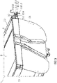
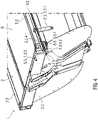
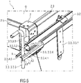
Figuren 3 bis 5 sind verschiedene Ausschnitte eines ersten Ausführungsbeispiels eines Ladegutbehälters 1 für ein Fahrzeug mit einer arretierten Handkurbel 3.3.3 aus verschiedenen Perspektiven dargestellt. Die Plane 3.1 ist aus Gründen der Übersichtlichkeit nicht dargestellt. - Die Funktion des Ladegutbehälters 1 mit dem Behälterkörper 2 und der Abdeckvorrichtung 3 entspricht der beschriebenen Funktion des in den
Figuren 1 und 2 dargestellten Ausführungsbeispiels des Ladegutbehälters 1. - Im dargestellten Ausführungsbeispiel umfasst die Konsole 3.3.4 eine Arretierstruktur 3.3.4.2, welche eine in die Auflagefläche 3.3.4.1 eingebrachte Aussparung A umfasst. Die Aussparung A ist in einer Richtung, welche vom Behälterkörper 2 in Längsrichtung des Wickelkerns 3.2 weggerichtet ist, geöffnet, so dass die Handkurbel 3.3.3 durch Bewegung in Längsrichtung des Wickelkerns 3.2 aus dem Betriebszustand in den Freilaufzustand bewegbar ist.
- Um die Handkurbel 3.3.3 in der Arretierstruktur 3.3.4.2 anzuordnen und gegen eine Drehung zu sichern, wird diese nach Spannen der Plane 3.1 und Verklemmen des Wickelkerns 3.2 auf der Auflagefläche 3.3.4.1 der Konsole 3.3.4 soweit aus dem Wickelkern 3.2 herausgezogen, dass ein Hebelarm 3.3.3.3 derselben von der Konsole 3.3.4 beabstandet ist. Hierbei befindet sich die Handkurbel 3.3.3 in ihrem Freilaufzustand, welcher in
Figur 6 näher dargestellt ist. - Anschließend kann die Handkurbel 3.3.3 in eine Position gedreht werden, in welcher der Hebelarm 3.3.3.3 zumindest im Wesentlichen in Richtung einer Hochachse des Behälterkörpers 2 verläuft.
- Anschließend wird die Handkurbel 3.3.3 wieder in Richtung des Wickelkerns 3.2 und in die Aussparung A eingeführt. Somit ist diese und ist der Wickelkern 3.2 gegen eine Drehung gesichert. Dadurch bildet die Aussparung A eine Drehsperre.
- Weiterhin umfasst die Aussparung A mit dem Hebelarm 3.3.3.3 korrelierende Sperrstrukturen A1 bis A3, welche die Handkurbel 3.3.3 bei Anlage des Hebelarms 3.3.3.3 in einer von diesen gehaltenen und durch eine gewollte Drehbewegung des Wickelkerns 3.2 und eines dadurch erzeugten Drucks gegen eine Bewegung der Handkurbel 3.3.3 aus ihrem Betriebszustand in den Freilaufzustand sichern. Somit bildet die Aussparung A gleichzeitig eine Sperre zur Sperrung einer Bewegung der Handkurbel 3.3.3 aus ihrem Betriebszustand in den Freilaufzustand. Das heißt, diese Sperre und die Drehsperre sind in Form der Aussparung A als gemeinsames Element ausgebildet.
- In einer nicht näher dargestellten Ausgestaltung kann im Bereich der Sperrstrukturen A1 bis A3 zumindest ein in den
Figuren 9 und10 näher dargestelltes Rastelement R befestigt sein, in welchem der Hebelarm 3.3.3.3 der Handkurbel 3.3.3 zusätzlich verrastbar ist. -
Figur 6 zeigt einen Ausschnitt des ersten Ausführungsbeispiels des Ladegutbehälters 1 mit einer nicht arretierten Handkurbel 3.3.3 im Freilaufzustand. - Das Eingriffselement 3.3.3.1 der Handkurbel 3.3.3 weist eine Außenverzahnung auf, welche in das Eingriffselement 3.2.1 des Wickelkerns 3.2 in verschiedenen relativen Positionen zueinander eingreifen kann.
- In
Figur 7 ist eine perspektivische Ansicht eines zweiten Ausführungsbeispiels eines Ladegutbehälters 1 für ein Fahrzeug mit einer arretierten Handkurbel 3.3.3 dargestellt.Figur 8 zeigt einen Ausschnitt des zweiten Ausführungsbeispiels des Ladegutbehälters 1 mit einer nicht arretierten Handkurbel 3.3.3 im Freilaufzustand. - Im Unterschied zu dem in den
Figuren 3 bis 6 dargestellten ersten Ausführungsbeispiel des Ladegutbehälters 1 umfasst die Arretierstruktur 3.3.4.2 eine in die Auflagefläche 3.3.4.1 eingebrachte Aussparung A, welche in einer Richtung, welche senkrecht von der Längsrichtung des Wickelkerns 3.2 in Querrichtung des Behälterkörpers 2 weggerichtet ist, offen ist. Dabei bildet die Aussparung A eine Drehsperre, in welcher die Handkurbel 3.3.3 und der Wickelkern 3.2 gegen eine Drehung gesichert sind. Gleichzeitig bildet die Aussparung A durch ihre vom Wickelkern 3.2 weg gerichtete Begrenzung eine Sperre zur Sperrung einer Bewegung der Handkurbel 3.3.3 aus ihrem Betriebszustand in den Freilaufzustand. - In einer nicht näher dargestellten Ausgestaltung kann im Bereich der Aussparung A zumindest ein in den
Figuren 9 und10 näher dargestelltes Rastelement R befestigt sein, in welchem der Hebelarm 3.3.3.3 der Handkurbel 3.3.3 zusätzlich verrastbar ist. - In
Figur 9 ist eine perspektivische Ansicht eines dritten Ausführungsbeispiels eines Ladegutbehälters 1 für ein Fahrzeug mit einer arretierten Handkurbel 3.3.3 dargestellt.Figur 10 zeigt einen Ausschnitt des dritten Ausführungsbeispiels des Ladegutbehälters 1 mit einer nicht arretierten Handkurbel 3.3.3 im Freilaufzustand. - Im Unterschied zu dem in den
Figuren 3 bis 6 dargestellten ersten Ausführungsbeispiel des Ladegutbehälters 1 umfasst die Aussparung A keine Sperrstrukturen A1 bis A3, jedoch ein Rastelement R, in welchem der Hebelarm 3.3.3.3 der Handkurbel 3.3.3 verrastbar und somit gemeinsam mit dem Wickelkern 3.2 gegen eine Drehung gesichert ist. Gleichzeitig bildet das Rastelement R durch die mögliche Verrastung eine Sperre zur Sperrung einer Bewegung der Handkurbel 3.3.3 aus ihrem Betriebszustand in den Freilaufzustand. -
- 1
- Ladegutbehälter
- 2
- Behälterkörper
- 2.1
- Behälterboden
- 2.2
- Behälterseite
- 2.3
- Behälterseite
- 2.4
- Behälterklappe
- 2.5
- Stirnwand
- 3
- Abdeckvorrichtung
- 3.1
- Plane
- 3.2
- Wickelkern
- 3.2.1
- Eingriffselement
- 3.3
- Planenspannvorrichtung
- 3.3.1
- Aufnahmehaken
- 3.3.2
- Aufnahmehaken
- 3.3.3
- Handkurbel
- 3.3.3.1
- Eingriffselement
- 3.3.3.2
- Abschnitt
- 3.3.3.3
- Hebelarm
- 3.3.4
- Konsole
- 3.3.4.1
- Auflagefläche
- 3.3.4.2
- Arretierstruktur
- A
- Aussparung
- A1 bis A3
- Sperrstruktur
- O
- Behälteröffnung
- R
- Rastelement
Claims (15)
- Ladegutbehälter (1) für ein Fahrzeug mit- einem Behälterkörper (2), umfassend eine obere Behälteröffnung (O),- einer Abdeckvorrichtung (3) für die Behälteröffnung (O) mit einer Plane (3.1), einem länglichen Wickelkern (3.2) und einer Planenspannvorrichtung (3.3), wobei- der Wickelkern (3.2) sich mit seiner Längsachse in einer ersten Position entlang einer ersten Behälterseite (2.2) und in einer zweiten Position entlang einer der ersten Behälterseite (2.2) gegenüberliegenden zweiten Behälterseite (2.3) erstreckt,- die Plane (3.1) einseitig an der ersten Behälterseite (2.2) und mit einer gegenüberliegenden Planenseite an dem Wickelkern (3.2) befestigt ist,- die Plane (3.1) in einer die Behälteröffnung (O) verschließenden Verschlussstellung zumindest teilweise von dem Wickelkern (3.2) abgewickelt, über die Behälteröffnung (O) geführt und an der zweiten Behälterseite (2.3) und über den Wickelkern (3.2) an dem Behälterkörper (2) arretiert und gespannt ist,- die Planenspannvorrichtung (3.3) zumindest eine an einer Längsseite an dem Wickelkern (3.2) angeordnete Handkurbel (3.3.3) zur Erzeugung einer Drehung des Wickelkerns (3.2) um seine Längsachse umfasst, wobei die Handkurbel (3.3.3) in einem Betriebszustand mit dem Wickelkern (3.2) in mechanischem Eingriff steht und in einem von dem Betriebszustand abweichenden Freilaufzustand der mechanische Eingriff gelöst ist,- die Planenspannvorrichtung (3.3) zumindest zwei in Längsausdehnung der zweiten Behälterseite (2.3) an dieser voneinander beabstandet angeordnete Aufnahmehaken (3.3.1, 3.3.2) umfasst, in welche der Wickelkern (3.2) an verschiedenen Längspositionen einhakbar und bei Ausführung einer Drehung desselben in Aufwickelrichtung der Plane (3.1) die Plane (3.1) spannbar ist, dadurch gekennzeichnet, dass- die Planenspannvorrichtung (3.3) zumindest eine Konsole (3.3.4) umfasst, welche an einem der Handkurbel (3.3.3) im gespannten Zustand der Plane (3.1) zugewandten Ende der zweiten Behälterseite (2.3) befestigt ist,- die Konsole (3.3.4) eine obere Auflagefläche (3.3.4.1) für eine Auflage des mit der Handkurbel (3.3.3) versehenen Endes des Wickelkerns (3.2) umfasst,- die Konsole (3.3.4) derart höhenpositioniert an der zweiten Behälterseite (2.3) befestigt ist, dass der Wickelkern (3.2) im gespannten Zustand der Plane (3.1) geklemmt auf der oberen Auflagefläche (3.3.4.1) aufliegt und- eine Auslenkung des mit der Handkurbel (3.3.3) versehenen Endes des Wickelkerns (3.2) die Klemmung bewirkt.
- Ladegutbehälter (1) nach Anspruch 1,
dadurch gekennzeichnet, dass die Konsole (3.3.4) eine Arretierstruktur (3.3.4.2) zur Arretierung der Handkurbel (3.3.3) in ihrem Betriebszustand im gespannten Zustand der Plane (3.1) umfasst. - Ladegutbehälter (1) nach Anspruch 2,
dadurch gekennzeichnet, dass die Arretierstruktur (3.3.4.2) zumindest eine Sperre zur Sperrung einer Bewegung der Handkurbel (3.3.3) aus ihrem Betriebszustand in den Freilaufzustand umfasst. - Ladegutbehälter (1) nach Anspruch 3,
dadurch gekennzeichnet, dass die Sperre derart ausgerichtet ist, dass ein Hebelarm (3.3.3.3) der Handkurbel (3.3.3) im arretierten Zustand zumindest im Wesentlichen in Richtung einer Hochachse des Behälterkörpers (2) verläuft. - Ladegutbehälter (1) nach Anspruch 3 oder 4,
dadurch gekennzeichnet, dass die Sperre ein Rastelement (R) zur Verrastung der Handkurbel (3.3.3) umfasst. - Ladegutbehälter (1) nach einem der Ansprüche 2 bis 5,
dadurch gekennzeichnet, dass die Arretierstruktur (3.3.4.2) zumindest eine Drehsperre zur Sperrung einer Bewegung der Handkurbel (3.3.3) und einer damit verbundenen Drehung des Wickelkerns (3.2) entgegen der Aufwickelrichtung der Plane (3.1) umfasst. - Ladegutbehälter (1) nach Anspruch 6,
dadurch gekennzeichnet, dass die Drehsperre derart ausgerichtet ist, dass ein Hebelarm (3.3.3.3) der Handkurbel (3.3.3) im arretierten Zustand zumindest im Wesentlichen in Richtung einer Hochachse des Behälterkörpers (2) verläuft. - Ladegutbehälter (1) nach Anspruch 6 oder 7,
dadurch gekennzeichnet, dass die Drehsperre ein Rastelement (R) zur Verrastung der Handkurbel (3.3.3) umfasst. - Ladegutbehälter (1) nach einem der Ansprüche 6 bis 8,
dadurch gekennzeichnet, dass die Sperre und die Drehsperre als gemeinsames Element ausgebildet sind. - Ladegutbehälter (1) nach einem der vorhergehenden Ansprüche,
dadurch gekennzeichnet, dass die Auslenkung des Wickelkerns (3.2) 10 mm bis 20 mm beträgt. - Ladegutbehälter (1) nach einem der vorhergehenden Ansprüche,
dadurch gekennzeichnet, dass die Auslenkung des Wickelkerns (3.2) zumindest im Wesentlichen in Richtung einer Hochachse des Behälterkörpers (2) ausgebildet ist. - Ladegutbehälter (1) nach einem der vorhergehenden Ansprüche,
dadurch gekennzeichnet, dass- der Wickelkern (3.2) zumindest im Bereich seines mit der Handkurbel (3.3.3) versehenen Endes als Hohlkörper ausgebildet ist,- innerhalb des Hohlkörpers ein Eingriffselement (3.2.1) angeordnet oder ausgebildet ist,- die Handkurbel (3.3.3) ein mit dem Eingriffselement (3.2.1) korrelierendes zweites Eingriffselement (3.3.3.1) umfasst,- ein das zweite Eingriffselement (3.3.3.1) umfassender Abschnitt (3.3.3.2) der Handkurbel (3.3.3) konzentrisch innerhalb des Hohlkörpers anordbar ist,- die beiden Eingriffselemente (3.2.1, 3.3.3.1) im Betriebszustand der Handkurbel (3.3.3) in mechanischem Eingriff stehen und- der Abschnitt (3.3.3.2) der Handkurbel (3.3.3) im Freilaufzustand der Handkurbel (3.3.3) in Längsrichtung des Wickelkerns (3.2) zum mit der Handkurbel (3.3.3) versehenen Ende des Wickelkerns (3.2) verschoben ist. - Ladegutbehälter (1) nach einem der vorhergehenden Ansprüche,
dadurch gekennzeichnet, dass die Plane (3.1) in einer die Behälteröffnung (O) freigebenden Öffnungsstellung auf dem Wickelkern (3.2) aufgewickelt im Bereich der ersten Behälterseite (2.2) angeordnet ist. - Fahrzeug, umfassend zumindest einen Ladegutbehälter (1) nach einem der vorhergehenden Ansprüche.
- Fahrzeug nach Anspruch 14, wobei der Ladegutbehälter (1) eine Kippmulde ist.
Priority Applications (2)
| Application Number | Priority Date | Filing Date | Title |
|---|---|---|---|
| PL20168774.6T PL3892483T3 (pl) | 2020-04-08 | 2020-04-08 | Pojemnik ładunkowy i pojazd |
| EP20168774.6A EP3892483B1 (de) | 2020-04-08 | 2020-04-08 | Ladegutbehälter und fahrzeug |
Applications Claiming Priority (1)
| Application Number | Priority Date | Filing Date | Title |
|---|---|---|---|
| EP20168774.6A EP3892483B1 (de) | 2020-04-08 | 2020-04-08 | Ladegutbehälter und fahrzeug |
Publications (2)
| Publication Number | Publication Date |
|---|---|
| EP3892483A1 EP3892483A1 (de) | 2021-10-13 |
| EP3892483B1 true EP3892483B1 (de) | 2022-08-24 |
Family
ID=70277224
Family Applications (1)
| Application Number | Title | Priority Date | Filing Date |
|---|---|---|---|
| EP20168774.6A Active EP3892483B1 (de) | 2020-04-08 | 2020-04-08 | Ladegutbehälter und fahrzeug |
Country Status (2)
| Country | Link |
|---|---|
| EP (1) | EP3892483B1 (de) |
| PL (1) | PL3892483T3 (de) |
Family Cites Families (3)
| Publication number | Priority date | Publication date | Assignee | Title |
|---|---|---|---|---|
| US6641199B1 (en) * | 2001-09-14 | 2003-11-04 | W. Glen Hicks | Dual side tarp |
| CA2428891C (en) * | 2003-05-16 | 2006-04-04 | Real Royer | Tarpaulin rod securing device |
| DE102014221384A1 (de) | 2014-10-21 | 2016-05-04 | Franz Xaver Meiller Fahrzeug- Und Maschinenfabrik - Gmbh & Co Kg | Planenabdeckvorrichtung sowie ein damit ausgestatteter Behälter mit einer oberen Beladeöffnung |
-
2020
- 2020-04-08 EP EP20168774.6A patent/EP3892483B1/de active Active
- 2020-04-08 PL PL20168774.6T patent/PL3892483T3/pl unknown
Also Published As
| Publication number | Publication date |
|---|---|
| EP3892483A1 (de) | 2021-10-13 |
| PL3892483T3 (pl) | 2022-11-21 |
Similar Documents
| Publication | Publication Date | Title |
|---|---|---|
| DE2403238C3 (de) | Kraftfahrzeugtürverschluli mit zwei gegenüberliegenden Sperrklinken und einer Gabelfalle | |
| WO1998024660A2 (de) | Sicherheitsnetzanordnung mit vereinfachter bedienung | |
| DE60018954T2 (de) | Türverriegelungssystem für einen container | |
| DE2604615B2 (de) | Sicherheits-Lasthaken | |
| DE2245802C3 (de) | Rückzieheinrichtung für einen Sicherheitsgurt | |
| DE3302303A1 (de) | Gurtrueckspuler | |
| DE8913486U1 (de) | Vorrichtung zum Betätigen eines Deckels einer Kraftfahrzeugkarosserie | |
| EP0156379A2 (de) | Kassenlade für eine Registrierkasse | |
| EP1900569B1 (de) | Ratschenanordnung zum Spannen aufwickelbarer Gegenstände | |
| EP0600228B1 (de) | Vorrichtung zum Öffnen und Schliessen eines Lukendeckels an einem Kampffahrzeug, insbesondere einem Kampfpanzer | |
| EP0588262A1 (de) | Verfahren und Vorrichtung zur Straffung von Sicherheitsgurten | |
| DE4013158C2 (de) | Abdeckrollo für Kraftfahrzeuge | |
| EP3892483A1 (de) | Ladegutbehälter und fahrzeug | |
| EP0471875A1 (de) | Eisenbahngüterwagen | |
| DE69702008T2 (de) | Fenster mit einem Treibstangenschloss und einer Auftriebsvorrichtung | |
| DE1580485C3 (de) | Vorrichtung zum Verriegeln des hinteren Endes eines kippbaren Fahrerhauses | |
| DE3048652C2 (de) | Handbetätigungsanordnung für Frachtladesysteme | |
| DE202015105844U1 (de) | Fahrzeugaufbau | |
| DE3839464C2 (de) | ||
| DE3722604C2 (de) | Wendevorrichtung für Rafflamellenstores | |
| DE102021122625A1 (de) | Containerverriegelungsvorrichtung sowie Containerverriegelungsverfahren | |
| EP3192952B1 (de) | Kraftfahrzeugschloss | |
| DE4135663C1 (en) | Roll cover for vehicle load space - is supported by cross-struts sliding in rails and fitting into boxes at ends of rails | |
| AT403361B (de) | Verriegelungsvorrichtung für die pendelachse einer schwenk- und pendelbaren bordwand einer kippbaren ladebrücke | |
| DE2009604C3 (de) | Türverschluß mit Gabelfalle, insbesondere für KFZ-Türen |
Legal Events
| Date | Code | Title | Description |
|---|---|---|---|
| PUAI | Public reference made under article 153(3) epc to a published international application that has entered the european phase |
Free format text: ORIGINAL CODE: 0009012 |
|
| STAA | Information on the status of an ep patent application or granted ep patent |
Free format text: STATUS: THE APPLICATION HAS BEEN PUBLISHED |
|
| AK | Designated contracting states |
Kind code of ref document: A1 Designated state(s): AL AT BE BG CH CY CZ DE DK EE ES FI FR GB GR HR HU IE IS IT LI LT LU LV MC MK MT NL NO PL PT RO RS SE SI SK SM TR |
|
| STAA | Information on the status of an ep patent application or granted ep patent |
Free format text: STATUS: REQUEST FOR EXAMINATION WAS MADE |
|
| 17P | Request for examination filed |
Effective date: 20211025 |
|
| RBV | Designated contracting states (corrected) |
Designated state(s): AL AT BE BG CH CY CZ DE DK EE ES FI FR GB GR HR HU IE IS IT LI LT LU LV MC MK MT NL NO PL PT RO RS SE SI SK SM TR |
|
| INTG | Intention to grant announced |
Effective date: 20220318 |
|
| RIC1 | Information provided on ipc code assigned before grant |
Ipc: B60J 7/10 20060101ALI20220304BHEP Ipc: B65H 18/10 20060101ALI20220304BHEP Ipc: B60J 7/08 20060101AFI20220304BHEP |
|
| GRAS | Grant fee paid |
Free format text: ORIGINAL CODE: EPIDOSNIGR3 |
|
| STAA | Information on the status of an ep patent application or granted ep patent |
Free format text: STATUS: GRANT OF PATENT IS INTENDED |
|
| GRAA | (expected) grant |
Free format text: ORIGINAL CODE: 0009210 |
|
| STAA | Information on the status of an ep patent application or granted ep patent |
Free format text: STATUS: THE PATENT HAS BEEN GRANTED |
|
| AK | Designated contracting states |
Kind code of ref document: B1 Designated state(s): AL AT BE BG CH CY CZ DE DK EE ES FI FR GB GR HR HU IE IS IT LI LT LU LV MC MK MT NL NO PL PT RO RS SE SI SK SM TR |
|
| REG | Reference to a national code |
Ref country code: CH Ref legal event code: EP |
|
| REG | Reference to a national code |
Ref country code: DE Ref legal event code: R096 Ref document number: 502020001564 Country of ref document: DE |
|
| REG | Reference to a national code |
Ref country code: IE Ref legal event code: FG4D Free format text: LANGUAGE OF EP DOCUMENT: GERMAN |
|
| REG | Reference to a national code |
Ref country code: AT Ref legal event code: REF Ref document number: 1513411 Country of ref document: AT Kind code of ref document: T Effective date: 20220915 |
|
| REG | Reference to a national code |
Ref country code: LT Ref legal event code: MG9D |
|
| REG | Reference to a national code |
Ref country code: NL Ref legal event code: MP Effective date: 20220824 |
|
| PG25 | Lapsed in a contracting state [announced via postgrant information from national office to epo] |
Ref country code: SE Free format text: LAPSE BECAUSE OF FAILURE TO SUBMIT A TRANSLATION OF THE DESCRIPTION OR TO PAY THE FEE WITHIN THE PRESCRIBED TIME-LIMIT Effective date: 20220824 Ref country code: RS Free format text: LAPSE BECAUSE OF FAILURE TO SUBMIT A TRANSLATION OF THE DESCRIPTION OR TO PAY THE FEE WITHIN THE PRESCRIBED TIME-LIMIT Effective date: 20220824 Ref country code: PT Free format text: LAPSE BECAUSE OF FAILURE TO SUBMIT A TRANSLATION OF THE DESCRIPTION OR TO PAY THE FEE WITHIN THE PRESCRIBED TIME-LIMIT Effective date: 20221226 Ref country code: NO Free format text: LAPSE BECAUSE OF FAILURE TO SUBMIT A TRANSLATION OF THE DESCRIPTION OR TO PAY THE FEE WITHIN THE PRESCRIBED TIME-LIMIT Effective date: 20221124 Ref country code: NL Free format text: LAPSE BECAUSE OF FAILURE TO SUBMIT A TRANSLATION OF THE DESCRIPTION OR TO PAY THE FEE WITHIN THE PRESCRIBED TIME-LIMIT Effective date: 20220824 Ref country code: LV Free format text: LAPSE BECAUSE OF FAILURE TO SUBMIT A TRANSLATION OF THE DESCRIPTION OR TO PAY THE FEE WITHIN THE PRESCRIBED TIME-LIMIT Effective date: 20220824 Ref country code: LT Free format text: LAPSE BECAUSE OF FAILURE TO SUBMIT A TRANSLATION OF THE DESCRIPTION OR TO PAY THE FEE WITHIN THE PRESCRIBED TIME-LIMIT Effective date: 20220824 Ref country code: FI Free format text: LAPSE BECAUSE OF FAILURE TO SUBMIT A TRANSLATION OF THE DESCRIPTION OR TO PAY THE FEE WITHIN THE PRESCRIBED TIME-LIMIT Effective date: 20220824 |
|
| PG25 | Lapsed in a contracting state [announced via postgrant information from national office to epo] |
Ref country code: IS Free format text: LAPSE BECAUSE OF FAILURE TO SUBMIT A TRANSLATION OF THE DESCRIPTION OR TO PAY THE FEE WITHIN THE PRESCRIBED TIME-LIMIT Effective date: 20221224 Ref country code: HR Free format text: LAPSE BECAUSE OF FAILURE TO SUBMIT A TRANSLATION OF THE DESCRIPTION OR TO PAY THE FEE WITHIN THE PRESCRIBED TIME-LIMIT Effective date: 20220824 Ref country code: GR Free format text: LAPSE BECAUSE OF FAILURE TO SUBMIT A TRANSLATION OF THE DESCRIPTION OR TO PAY THE FEE WITHIN THE PRESCRIBED TIME-LIMIT Effective date: 20221125 |
|
| PG25 | Lapsed in a contracting state [announced via postgrant information from national office to epo] |
Ref country code: SM Free format text: LAPSE BECAUSE OF FAILURE TO SUBMIT A TRANSLATION OF THE DESCRIPTION OR TO PAY THE FEE WITHIN THE PRESCRIBED TIME-LIMIT Effective date: 20220824 Ref country code: RO Free format text: LAPSE BECAUSE OF FAILURE TO SUBMIT A TRANSLATION OF THE DESCRIPTION OR TO PAY THE FEE WITHIN THE PRESCRIBED TIME-LIMIT Effective date: 20220824 Ref country code: ES Free format text: LAPSE BECAUSE OF FAILURE TO SUBMIT A TRANSLATION OF THE DESCRIPTION OR TO PAY THE FEE WITHIN THE PRESCRIBED TIME-LIMIT Effective date: 20220824 Ref country code: DK Free format text: LAPSE BECAUSE OF FAILURE TO SUBMIT A TRANSLATION OF THE DESCRIPTION OR TO PAY THE FEE WITHIN THE PRESCRIBED TIME-LIMIT Effective date: 20220824 |
|
| REG | Reference to a national code |
Ref country code: DE Ref legal event code: R097 Ref document number: 502020001564 Country of ref document: DE |
|
| PG25 | Lapsed in a contracting state [announced via postgrant information from national office to epo] |
Ref country code: SK Free format text: LAPSE BECAUSE OF FAILURE TO SUBMIT A TRANSLATION OF THE DESCRIPTION OR TO PAY THE FEE WITHIN THE PRESCRIBED TIME-LIMIT Effective date: 20220824 Ref country code: EE Free format text: LAPSE BECAUSE OF FAILURE TO SUBMIT A TRANSLATION OF THE DESCRIPTION OR TO PAY THE FEE WITHIN THE PRESCRIBED TIME-LIMIT Effective date: 20220824 |
|
| PG25 | Lapsed in a contracting state [announced via postgrant information from national office to epo] |
Ref country code: AL Free format text: LAPSE BECAUSE OF FAILURE TO SUBMIT A TRANSLATION OF THE DESCRIPTION OR TO PAY THE FEE WITHIN THE PRESCRIBED TIME-LIMIT Effective date: 20220824 |
|
| PLBE | No opposition filed within time limit |
Free format text: ORIGINAL CODE: 0009261 |
|
| STAA | Information on the status of an ep patent application or granted ep patent |
Free format text: STATUS: NO OPPOSITION FILED WITHIN TIME LIMIT |
|
| 26N | No opposition filed |
Effective date: 20230525 |
|
| PG25 | Lapsed in a contracting state [announced via postgrant information from national office to epo] |
Ref country code: SI Free format text: LAPSE BECAUSE OF FAILURE TO SUBMIT A TRANSLATION OF THE DESCRIPTION OR TO PAY THE FEE WITHIN THE PRESCRIBED TIME-LIMIT Effective date: 20220824 |
|
| P01 | Opt-out of the competence of the unified patent court (upc) registered |
Effective date: 20230810 |
|
| REG | Reference to a national code |
Ref country code: CH Ref legal event code: PL |
|
| PG25 | Lapsed in a contracting state [announced via postgrant information from national office to epo] |
Ref country code: LU Free format text: LAPSE BECAUSE OF NON-PAYMENT OF DUE FEES Effective date: 20230408 |
|
| PG25 | Lapsed in a contracting state [announced via postgrant information from national office to epo] |
Ref country code: MC Free format text: LAPSE BECAUSE OF FAILURE TO SUBMIT A TRANSLATION OF THE DESCRIPTION OR TO PAY THE FEE WITHIN THE PRESCRIBED TIME-LIMIT Effective date: 20220824 |
|
| PG25 | Lapsed in a contracting state [announced via postgrant information from national office to epo] |
Ref country code: MC Free format text: LAPSE BECAUSE OF FAILURE TO SUBMIT A TRANSLATION OF THE DESCRIPTION OR TO PAY THE FEE WITHIN THE PRESCRIBED TIME-LIMIT Effective date: 20220824 Ref country code: LI Free format text: LAPSE BECAUSE OF NON-PAYMENT OF DUE FEES Effective date: 20230430 Ref country code: CH Free format text: LAPSE BECAUSE OF NON-PAYMENT OF DUE FEES Effective date: 20230430 |
|
| REG | Reference to a national code |
Ref country code: IE Ref legal event code: MM4A |
|
| PG25 | Lapsed in a contracting state [announced via postgrant information from national office to epo] |
Ref country code: IE Free format text: LAPSE BECAUSE OF NON-PAYMENT OF DUE FEES Effective date: 20230408 |
|
| PG25 | Lapsed in a contracting state [announced via postgrant information from national office to epo] |
Ref country code: IE Free format text: LAPSE BECAUSE OF NON-PAYMENT OF DUE FEES Effective date: 20230408 |
|
| PG25 | Lapsed in a contracting state [announced via postgrant information from national office to epo] |
Ref country code: BG Free format text: LAPSE BECAUSE OF FAILURE TO SUBMIT A TRANSLATION OF THE DESCRIPTION OR TO PAY THE FEE WITHIN THE PRESCRIBED TIME-LIMIT Effective date: 20220824 |
|
| PG25 | Lapsed in a contracting state [announced via postgrant information from national office to epo] |
Ref country code: BG Free format text: LAPSE BECAUSE OF FAILURE TO SUBMIT A TRANSLATION OF THE DESCRIPTION OR TO PAY THE FEE WITHIN THE PRESCRIBED TIME-LIMIT Effective date: 20220824 |
|
| PGFP | Annual fee paid to national office [announced via postgrant information from national office to epo] |
Ref country code: PL Payment date: 20250328 Year of fee payment: 6 Ref country code: CZ Payment date: 20250326 Year of fee payment: 6 |
|
| PGFP | Annual fee paid to national office [announced via postgrant information from national office to epo] |
Ref country code: DE Payment date: 20250327 Year of fee payment: 6 |
|
| PGFP | Annual fee paid to national office [announced via postgrant information from national office to epo] |
Ref country code: GB Payment date: 20250423 Year of fee payment: 6 |
|
| PGFP | Annual fee paid to national office [announced via postgrant information from national office to epo] |
Ref country code: IT Payment date: 20250430 Year of fee payment: 6 Ref country code: BE Payment date: 20250422 Year of fee payment: 6 |
|
| PGFP | Annual fee paid to national office [announced via postgrant information from national office to epo] |
Ref country code: FR Payment date: 20250428 Year of fee payment: 6 |
|
| PGFP | Annual fee paid to national office [announced via postgrant information from national office to epo] |
Ref country code: AT Payment date: 20250416 Year of fee payment: 6 |
|
| PG25 | Lapsed in a contracting state [announced via postgrant information from national office to epo] |
Ref country code: CY Free format text: LAPSE BECAUSE OF FAILURE TO SUBMIT A TRANSLATION OF THE DESCRIPTION OR TO PAY THE FEE WITHIN THE PRESCRIBED TIME-LIMIT; INVALID AB INITIO Effective date: 20200408 |
|
| PG25 | Lapsed in a contracting state [announced via postgrant information from national office to epo] |
Ref country code: HU Free format text: LAPSE BECAUSE OF FAILURE TO SUBMIT A TRANSLATION OF THE DESCRIPTION OR TO PAY THE FEE WITHIN THE PRESCRIBED TIME-LIMIT; INVALID AB INITIO Effective date: 20200408 |
|
| PG25 | Lapsed in a contracting state [announced via postgrant information from national office to epo] |
Ref country code: TR Free format text: LAPSE BECAUSE OF FAILURE TO SUBMIT A TRANSLATION OF THE DESCRIPTION OR TO PAY THE FEE WITHIN THE PRESCRIBED TIME-LIMIT Effective date: 20220824 |