EP3887301B1 - Verfahren zum montieren einer förderkette für ein palettenband eines fahrsteigs - Google Patents
Verfahren zum montieren einer förderkette für ein palettenband eines fahrsteigs Download PDFInfo
- Publication number
- EP3887301B1 EP3887301B1 EP19791269.4A EP19791269A EP3887301B1 EP 3887301 B1 EP3887301 B1 EP 3887301B1 EP 19791269 A EP19791269 A EP 19791269A EP 3887301 B1 EP3887301 B1 EP 3887301B1
- Authority
- EP
- European Patent Office
- Prior art keywords
- chain
- chain pin
- conveyor
- piece
- coupled
- Prior art date
- Legal status (The legal status is an assumption and is not a legal conclusion. Google has not performed a legal analysis and makes no representation as to the accuracy of the status listed.)
- Active
Links
Images



Classifications
-
- B—PERFORMING OPERATIONS; TRANSPORTING
- B66—HOISTING; LIFTING; HAULING
- B66B—ELEVATORS; ESCALATORS OR MOVING WALKWAYS
- B66B23/00—Component parts of escalators or moving walkways
- B66B23/02—Driving gear
- B66B23/024—Chains therefor
-
- B—PERFORMING OPERATIONS; TRANSPORTING
- B66—HOISTING; LIFTING; HAULING
- B66B—ELEVATORS; ESCALATORS OR MOVING WALKWAYS
- B66B21/00—Kinds or types of escalators or moving walkways
- B66B21/10—Moving walkways
-
- B—PERFORMING OPERATIONS; TRANSPORTING
- B66—HOISTING; LIFTING; HAULING
- B66B—ELEVATORS; ESCALATORS OR MOVING WALKWAYS
- B66B23/00—Component parts of escalators or moving walkways
- B66B23/02—Driving gear
- B66B23/022—Driving gear with polygon effect reduction means
-
- B—PERFORMING OPERATIONS; TRANSPORTING
- B66—HOISTING; LIFTING; HAULING
- B66B—ELEVATORS; ESCALATORS OR MOVING WALKWAYS
- B66B23/00—Component parts of escalators or moving walkways
- B66B23/08—Carrying surfaces
- B66B23/10—Carrying belts
Definitions
- the present invention relates to a method for installing a conveyor chain for a pallet belt of a moving walk, a method for replacing a connecting element in a conveyor chain and a method for installing a pallet belt for a moving walk, and such a conveyor chain, a pallet belt with such a conveyor chain and a moving walk with such a pallet strap.
- Moving walks are used as passenger transport systems to transport people within a building along a travel path that is usually horizontal or only slightly inclined.
- a moving walk has a pallet belt on which passengers can stand and which can be moved in all directions along the travel path.
- a large number of pallets are arranged one behind the other on the pallet belt.
- Each of the pallets is typically mounted between two conveyor chains positioned along opposite sides of the pallet belt.
- Each of the conveyor chains is in turn composed of a large number of elongated chain links, which are arranged one behind the other at a spacing and are pivotably connected to one another via chain pins, so that the entire conveyor chain can withstand high tensile loads.
- the spacing essentially corresponds to the distance between the central longitudinal axes of the chain pins.
- the pallet belt is arranged all around. This means that the pallets can be moved in a forward direction along the travel path using the conveyor chains. At the ends of the travel path, the pallet belt is deflected by deflection devices so that the pallets with the pallet belt that is closed in the form of a ring can be moved in the opposite return direction back to the start of the travel path.
- deflection devices usually have deflection sprockets, which each interact with one of the conveyor chains in order to deflect it from the forward direction to the return direction or vice versa, generally by 180°.
- a moving walk is to be installed in a building that is to be newly built, it can be provided that at least parts of the moving walk are integrated in a floor of the building, so that a running surface formed by the pallets in advance can end as flush as possible with a surface of this floor. It can be advantageous to provide moving walks with a low overall height for this purpose so that no deep pits in which the moving walk can be accommodated have to be provided in the floors of the structure.
- a moving walk is to be retrofitted in an already existing building, it may not be possible or at least very expensive in some cases, for example for reasons of statics, to sink it at least partially in a floor of the building. In this case, the moving walk must be set up on the floor of the structure.
- a height difference between a level on which the running surface of the moving walk runs and a level of the surrounding ground should be as small as possible.
- the aim should be to use a moving walkway with a particularly low overall height.
- the overall height of a moving walk is largely determined by the overall height of its deflection devices and in particular by a diameter of the deflection chain wheels used therein, which are usually arranged vertically.
- so-called polygon effects can occur due to the fact that not arbitrarily narrow pallets can be used, but the pallets have a minimum length for practical use (measured in the direction of the travel path).
- Such polygon effects can occur noticeably if the length of the pallets and the associated pitch of the conveyor chain are not sufficiently small compared to the diameter of the deflection sprockets.
- a minimum number of teeth of the deflection sprockets of 17 teeth and thus a minimum overall height was usually not undercut in conventional moving walks.
- a pallet belt for use in a conveyor system, in particular a moving walkway is described.
- the pallet belt described has two conveyor chains and pallets arranged between them.
- This pallet strap due to its structural design, can help to some extent Limiting polygon effects even when using small deflection sprockets.
- the structural design of the pallet belt described is relatively fragile and has a large number of safety-relevant components which, in the event of incorrect assembly or failure, could lead to dangerous situations for the user.
- connection elements that are adjacent in the direction of extension can be arranged so as to overlap one another.
- a second end of a front of the two connection elements and a first end of a rear of the two connection elements are each coupled to a common two-part chain pin. This is done in that the first chain pin part of the common two-part chain pin is coupled to the second end of the front of the two connection elements and the second chain pin part of the common two-part chain pin is coupled to the first end of the rear of the two connection elements.
- the first end of each of the connecting elements can be coupled to the respective first two-part chain pin in a pivotable and coaxially positioned manner and the second end of each of the connecting elements can be pivoted to the respective second two-part chain pin and can be coupled in the direction of extension over a predetermined distance be coupled linearly displaceable out.
- at least one of the connection elements is first coupled with the second end during the coupling process by sliding it on in the axial direction with the associated first chain pin part of the respective first two-part chain pin. Then the first end with the associated second chain pin part of the respective second two-part Coupled chain pin by the second chain pin part is firmly connected to the first chain pin part of the respective second two-part chain pin.
- the features coupling, coupling, coupled is understood in the present document to mean a connection that enables relative movements between the coupled parts in at least one direction of movement, but which does not allow the coupled parts to be separated without additional effort.
- Such an additional effort can be, for example, the loosening of a screw, a nut, a cotter pin, the actuation of a snap-in device or even an irreversible destruction of a coupling component and the like in order to break the coupling of the parts.
- a pluggable structure can be provided between the first chain pin part and the second chain pin part, so that the second chain pin part can be plugged together with the first chain pin part during assembly.
- an anti-twist device can be provided between the first chain pin part and the second chain pin part, which prevents the first chain pin part from twisting relative to the second chain pin part in a positive and/or cohesive manner.
- Projection and depression structures formed on the chain bolt parts for example, such as spring washers according to DIN 6796, can be provided as form-fitting anti-twist devices. In this case, these structures can also be provided on only one of the chain pin parts, with their projections being embossed in the other chain pin part during assembly. Additional machine elements such as pins or the like are also possible. Cohesive anti-twist devices such as anaerobic-curing adhesives are particularly advantageous.
- connection element can have a through-opening at the first end and at the second end.
- the respective two-part chain pin can extend through these in the coupled state.
- the first end of the connecting elements can each be held on the associated two-part chain pin via a sliding element, the sliding element being arranged on the associated two-part chain pin before the connecting element is pushed on axially. After the attachment element has been slid on axially, the sliding element is interposed between opposing surfaces of the attachment element on the one hand and the associated two-part chain pin on the other hand.
- the second end of the connecting element can be held on the associated two-part chain pin via a bushing, so that the bushing is interposed between the through-opening of the connecting element on the one hand and the associated two-part chain pin on the other when the connecting element is pushed on axially.
- each connecting element can be fastened with each of its ends to the respectively associated two-part chain pin with the aid of a fastening element that can be detached in the axial direction.
- the second chain pin part is preferably also firmly connected or secured to the first chain pin part.
- a method for replacing a connection element in a conveyor chain is proposed.
- the conveyor chain was assembled according to a method of the type described above and has corresponding structural properties resulting from these assembly methods.
- the method has at least the following steps, possibly, but not necessarily, in the specified order: First, the second chain pin part of the second two-part chain pin associated with the connection element to be exchanged is removed. Then, by pivoting the connection element following the connection element to be exchanged, the second end of the connection element to be exchanged is released, so that it can be decoupled from the associated second chain pin. After that you can Subtracting the first end and second end in the axial direction, the connection element to be replaced can be decoupled from the associated two-part chain pin.
- connection element detached and removed in this way can now be replaced by a replacement connection element.
- This is done by coupling the replacement connection element by sliding it in the axial direction onto the associated first and second two-part chain pins.
- the following connection element has to be coupled to the second two-part chain pin belonging to the replacement replacement element. This is done by pivoting the subsequent connection element into the intended position and by firmly connecting the second chain pin part to the first chain pin part of the second associated two-part chain pin.
- a method for assembling a pallet band for a moving walkway comprises at least the following steps, possibly but not necessarily in the order given:
- a first and a second conveyor chain are assembled according to an embodiment of the first aspect of the invention.
- the two conveyor chains are arranged parallel to each other.
- a plurality of pallets are then attached to the two conveyor chains, with the pallets being arranged one behind the other in the direction in which the conveyor chains extend.
- Each of the pallets is attached at a first lateral end to one of the connection elements of the first conveyor chain and at an opposite second lateral end to one of the connection elements of the second conveyor chain.
- the method according to the invention enables a structured and secure assembly of interlocking and overlapping elements or components of a conveyor chain or a pallet belt.
- interlocking and overarching elements ensure a high level of operational reliability.
- the special design of the interlocking and overarching elements also requires a structured approach when replacing elements.
- pallets were usually connected directly to possibly extended chain pins of the conveyor chains.
- conveyor chains with a relatively large pitch were used here, so that the length of the pallets essentially corresponded to the pitch of the conveyor chains.
- this mechanism is provided in the area where the pallets are connected to one or more of the chain pins with which the pallets are to be coupled.
- the structure of such a mechanism can be complex and/or sensitive.
- this type of connection of the pallets to the conveyor chains it can be expensive to assemble the pallet belt and/or to dismantle it, for example, as part of a maintenance process and/or to replace defective parts of the pallet belt, for example.
- Embodiments of the assembly method described herein make it possible to assemble a structurally and functionally specially designed conveyor chain in a simple manner or to be able to easily disassemble or replace components contained therein.
- the construction according to the invention increases the security against breakage of the conveyor chain through the formation of parallel chain structures.
- connection elements are provided to which the pallets can be attached.
- These connection elements form a kind of additional chain running parallel to the respective conveyor chain, with the connection elements being many times longer than the chain links of the conveyor chain, i.e. the additional chain formed from the connection elements has a greater pitch than the chain formed from the chain links. In other words, a connection element overlaps several chain links.
- the connection elements are coupled with some of the chain pins of the conveyor chain, which also couple the chain links. Since the connecting elements are longer than the chain links of the conveyor chains, the opposite ends of the connecting elements are each coupled to every second, every third or, more generally, every nth (n > 2) chain pin, i.e. between two chain pins coupled to a connecting element there is at least a chain pin that is not coupled to the attachment element.
- connection elements in connection with the above-described two-piece design of the chain pins are structurally suitable in order to be able to compensate for the differences in length that occur when the conveyor chains are deflected between the shorter chain links of the conveyor chains and the connection elements, which are longer in comparison.
- the conveyor chain can also be deflected around deflection sprockets with a small diameter, without polygon effects causing undesired effects.
- the pallets are not connected directly to the chain pins, but are indirectly connected to the two-part chain pins via the connection elements, it can be achieved, among other things, that the pallets and/or other components of the pallet belt can be easily assembled, disassembled or replaced.
- connection elements and two-part chain pins can be designed in such a way that by removing a second chain pin part, the connection element can be pivoted and thereby decoupled from the first chain pin part in the tangential direction.
- adjacent connection elements with their opposite Ends are coupled to a common two-piece chain pin can be individually detached from the respective two-piece chain pin.
- connection elements or pallets attached to them are to be replaced, for example because of wear, not all connection elements need to be detached from the chain formed by the chain links. Instead, for example, individual connection elements can be detached and replaced.
- the first chain pin parts can in each case project through second through-openings of the connection elements and the second chain pin parts can in each case project through first through-openings in the connection elements.
- a pallet belt for a moving walkway can be created which has a first and a second conveyor chain of the aforementioned configuration and includes a plurality of pallets which are arranged one behind the other in a direction in which the conveyor chains extend.
- the two conveyor chains are arranged parallel to one another, with each of the pallets being attached to one of the connecting elements of the first conveyor chain at a first lateral end and to one of the connecting elements of the second conveyor chain at an opposite second lateral end. Due to the design of the conveyor chain, each of the pallets can be at least an integer multiple longer than the chain links.
- This pallet band can be used in a moving walk that has two deflection devices, each with deflection sprockets for deflecting the pallet band in deflection areas at opposite ends of the moving walk.
- a moving walkway 1 is shown roughly schematically, with the aid of which passengers can be transported along a horizontal travel path.
- the moving walkway 1 has a pallet belt 3, the stepable, upward-pointing portion of which extends in a direction 17 along the travel path.
- This portion of the pallet band 3 that can be walked on is moved in a forward direction when the moving walkway 1 is in operation.
- the pallet band 3 is closed in a ring or arranged circumferentially and is deflected at opposite ends of the moving walk 1 by means of deflection sprockets 9, so that a portion of the pallet band directed downwards is moved back in a return direction.
- inclined ramps 11 are provided in an entrance area and in an exit area.
- a handrail 13 is arranged along the travel path, which is only shown with a broken line for reasons of clarity.
- the pallet belt 3 consists essentially of two conveyor chains 5 and several pallets 7 held on these conveyor chains 5.
- the conveyor chains 5 are parallel to one another and are arranged on opposite sides of the moving walk 1 in relation to a width direction (perpendicular to the plane of the drawing).
- Each conveyor chain 5 is composed of a large number of chain links which are pivotally coupled to one another by means of chain pins.
- the pallets 7 are mechanically connected to the two conveyor chains 5, so that moving the conveyor chains 5 also moves the pallets 7 along the travel path.
- the moving walkway 1 is built on a floor 15 .
- An overall height h should be as small as possible, for example in order to limit the length or inclination of the ramps 11 . Due to such a desired low overall height h, the diameter of the deflection chain wheels 9 should also be as small as possible.
- a length of the chain links forming the conveyor chain essentially corresponds to a length of the pallets.
- a pitch of the conventional conveyor chain essentially corresponds to a pitch of the conventional pallet band formed therewith.
- a pallet is connected at its front end and its rear end to one of the chain pins at the opposite ends of the chain link running parallel to the pallet 7 .
- the present invention relates to a moving walkway 1 and its components, such as in particular the pallet belt 3 and the conveyor chain 5, or a method for installing or repairing such components, in which the moving walkway 1 has a low overall height h can be provided without adjusting the deflection of the pallet band 3 unacceptable strong polygon effects. Furthermore, the present invention increases the operational safety of the moving walkway 1 due to its specific structural characteristics. In addition, the conveyor chain 5 and the pallet belt 3 formed with it can be easily installed and the components contained therein can be easily exchanged if necessary.
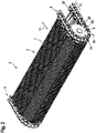
- a part of a moving walkway 1 is shown in perspective in a deflection area 19 .
- the pallet band 3 is deflected in the deflection area 19 by means of a deflection device 21 from a forward direction to a return direction or vice versa.
- the deflection device 21 has deflection chain wheels 9 in the form of gear wheels 23, which are arranged on opposite sides of the pallet belt 3 and interact with conveyor chains 5 running there.
- the deflection sprockets 9 have a small diameter of, for example, less than 40 cm, preferably less than 30 cm and more preferably less than 25 cm, so that the entire moving walk 1 has a low overall height h of, for example, significantly less than 50 cm, preferably even less than 35 cm , may have.
- the teeth 25 formed on the sprocket 23, which mesh with individual chain links 27 of the conveyor chain 5, can be arranged closely adjacent to each other. Accordingly, at least 17 teeth 25 can also be provided on the outer circumference of the small deflection chain wheel 9, so that polygon effects can remain negligible when the conveyor chains 5 rotate.
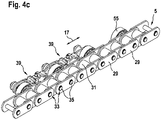
- the conveyor chain 5 has a number of elongated chain links 27 .
- the chain links 27 are arranged one behind the other along the extension direction 17 of the conveyor chain 5 .
- Each chain link 27 is in the example shown (see in particular Figure 4a ) formed with two parallel, sheet-like tabs 29. The tabs 29 are spaced apart from each other by sleeves 31 .
- Chain links 27 that are adjacent in the direction of extension 17 are each connected to one another in a joint area 33 by means of a chain pin 35 .
- the conveyor chain 5 can be subjected to high tensile loads and can be pivoted transversely to the direction of extent 17 about the respective central longitudinal axes M of the chain pins 35 .
- a distance between the central longitudinal axes M between two adjacent chain pins 35 on the conveyor chain 5 corresponds to the chain pitch distance T1.
- the individual chain links 27 of the conveyor chain 5 are so short that the chain pitch T1 is preferably shorter than 10 cm, more preferably shorter than 6 cm and in particular 50 mm ⁇ 2 mm. amounts to.
- the pallets 7 are usually connected directly to the chain pins 35 of the conveyor chains 5.
- the pallets 7 are directly connected at the lateral end faces to extended chain pins 35 that protrude laterally beyond the conveyor chains 5 .
- connection elements 39 are provided on the conveyor chain 5 in the case of the pallet belt 3 proposed here.
- the connecting elements 39 are arranged one behind the other in the direction of extent 17 or parallel to it.
- Two connection elements 39 that are adjacent in the direction of extent 17 are pivotally coupled to one another transversely to the direction of extent 17 .
- Such a coupling can take place, for example, via two-part chain pins 37 of the conveyor chain 5, which protrude laterally beyond the chain links 27 and with which the connection elements 39 can be connected.
- the two-part chain bolts 37 here have a first chain bolt part 36 and a second chain bolt part 38 .
- a pluggable structure 49 is preferably provided between the first chain pin part 36 and the second chain pin part 38 . This allows the second chain pin part 38 to be plugged together with the first chain pin part 36 during assembly, so that the two chain pin parts 36, 38 are precisely positioned relative to one another and assembly is made considerably easier. In particular, shear forces and bending moments acting between the two chain pin parts 36, 38 are efficiently transmitted via the pluggable structure 49.
- an anti-twist device 48 which, after assembly, prevents the first chain pin part 36 from rotating relative to the second chain pin part 38 in a form-fitting and/or cohesive manner.
- Projection and depression structures formed on the chain bolt parts for example, such as spring washers according to DIN 6796, can be provided as form-fitting anti-twist devices. In this case, these structures can also be provided on only one of the chain pin parts, with their projections being embossed in the other chain pin part during assembly. Additional machine elements such as pins or the like are also possible. Cohesive anti-twist devices such as anaerobic-curing adhesives are particularly advantageous.
- connection elements 39 can be coupled at a first end 41 to an associated first of the two-part chain pins 37 and be coupled at a second end 43 to an associated second of the two-part chain pins 37 .
- connection element pitch T2 A distance in the extension direction 17 between the central longitudinal axes M of the first and the second two-part chain pin 37 is referred to herein as the connecting element pitch T2.
- the connection elements 39 should be approximately an integer multiple, i.e. for example twice or three times longer than the chain links 27.
- each of the connecting elements 39 is not connected at its opposite ends 41, 43 to directly adjacent chain pins 35, 37. Instead, there is at least one chain pin 35, 37, which is not coupled to the connecting element 39, between two chain pins 35, 37, to which one of the respective ends 41, 43 of the connecting element 39 is connected. In other words, each of the connection elements 39 is only coupled to every second, every third or generally every nth of the chain pins 35, 37.
- connection elements 39 are coupled at their ends 41 , 43 to every third chain pin 35 , 37 , these chain pins 35 , 37 then being designed as two-part chain pins 37 . Between such two-part chain pins 37 there are in each case two shorter chain pins 35 which only connect the chain links 27 of the conveyor chain 5 but are not connected to the connection element 39 running parallel thereto.
- the pallets 7 are not directly connected to the conveyor chain 5. Instead, the pallets 7 are each attached to the connection elements 39 and indirectly connected to the chain links 27 of the conveyor chain 5 via these connection elements 39 .
- a length L of the pallets 7, measured in the extension direction 17, can correspond approximately to the connection element pitch T2 and thus be many times longer than the length of the chain links 27 and their chain pitch T1.
- the pallets 7 are slightly shorter than the connection element spacing T2, so that a small gap remains between adjacent pallets 7 and the pallets 7 can thus move relative to one another.
- a pallet length of almost 150 mm can be used for a conveyor chain 5 with a chain pitch T1 of 50 mm, so that each of the pallets 7 spans or “overlaps” several chain links 27 .
- connection elements 39 In order to be able to compensate for any shortening of the chord due to the longer connection elements 39 compared to the chain links 27 , a special configuration of the connection elements 39 or the manner in which they are connected to the conveyor chain 5 is necessary. In particular, at least one of the ends 41, 43 of each connection element 39 should be coupled to the conveyor chain 5 in such a way that length compensation can be created to compensate for the shortening of the chord.
- the two-part chain pins 37 described with a specific connection element 39 are referred to below as associated two-part chain pins 37 .
- the two-part chain pins 37 which interact with a specific area of the connecting element 39, are the first of the two-part chain pins 37 and the second of the two-part chain pins 37 or referred to as the first two-part chain pin 37 and the second two-part chain pin 37 in order to be able to describe their arrangement in relation to the associated connection element 39 .
- the ends of the attachment element 39 are referred to as the first end 41 and the second end 43 for the same reason, these designations not being intended to specify any direction of movement of the attachment element 39 in the direction of extension.
- first end 41 of a connecting element 39 can be pivoted and positioned coaxially with the first chain pin 37 .
- the first end 41 of the connecting element 39 can be coupled to the first two-part chain pin 37 in such a way that the connecting element 39 can pivot about the central longitudinal axis M of the first two-part chain pin 37, but in directions transverse to the central longitudinal axis M of the chain pin 37 relative to the two-part Chain pin 37 is position-bound.
- the first end 41 of the connecting element 39 is thus connected to the conveyor chain 5 so that it can pivot about the central longitudinal axis M of the two-part chain pin 37, but cannot be linearly displaced relative to it.
- the first end 41 of the connecting element 39 can be positively connected to the first two-part chain pin 37 in such a way that only pivoting movements about the central longitudinal axis M of the two-part chain pin 37 are possible, but no translational movements in the direction of extension 17 relative to the two-part chain pin 37 be allowed.
- each of the connecting elements 39 can be coupled to the second two-part chain pin 37 in a pivotable manner as well as being linearly guided in the direction of extent 17 and displaceable over a predetermined distance d.
- the second end 43 of the connecting element 39 can be coupled to the second two-part chain pin 37 in such a way that the connecting element 39 can pivot about the central longitudinal axis M of the second two-part chain pin 37 and additionally in a direction transverse to this central longitudinal axis M relative to the two-part chain pin 37 is displaceable over the predetermined distance d and it due to the design of the coupling between the connection element 39 and the second two-part chain pin 37 is guided in its linear movement.
- connection of the second end 43 of the connection element 39 to the second chain pin 37 can be configured in such a way that this second end 43 can move translationally in the direction transverse to the central longitudinal axis M of the two-part chain pin 37 relative to the second two-part chain pin 37 .
- This distance d can correspond to the length of the above-mentioned chord shortening or be greater than this.
- the distance d can correspond to the length by which the chord between the first and the second two-part chain pin 37 differs from the circumference along a circle segment when the conveyor chain 5 is deflected around the circle segment.
- the distance d can correspond to at least 150% or preferably at least 200% of the diameter of the second chain pin 37 .
- connection elements 39 described herein and their connection to the conveyor chain 5 a parallel chain is created, so to speak, the pitch of which is significantly greater than that of the chain links 27 and essentially corresponds to the length of the pallets 7 . Due to the structural and functional design of the connection elements 39 at their first and second ends 41, 43 and the way in which these ends are coupled to the two-part chain pins 37 of the conveyor chain 5, it is possible to achieve a shortening of the chord, as occurs when the pallet belt is deflected 3 is effected, can be compensated at the connection elements 39.
- the connecting element 39 has a through-opening 45, 47 at the first and at the second end 41, 43, through which the respective two-part chain pin 37 extends when coupled with the respective associated chain pin 37.
- through-openings 45, 47 should be formed at the opposite ends 41, 43 of the connecting element 39, through which the two-part chain pins 37 can extend.
- This through-openings 45, 47 can be dimensioned such that it is, for example, at of the first passage opening 45 comes to a partial form fit with the cylindrical, two-part chain pin 37 .
- the first through-opening 45 can be round, at least in some areas, and can have approximately the same diameter as the diameter of the two-part chain pin 37 .
- the second through-opening 47 in the connection element 39 can preferably be of elongate design, for example rectangular or quasi-rectangular.
- a length of this second passage opening 47 in the direction of extent 17 can correspond to the distance d by which the connection element 39 should be able to move relative to the associated two-part chain pin 37 .
- a height of this second passage opening 47 can correspond approximately to the diameter of the associated two-part chain pin 37 .
- adjacent connection elements 39 can overlap one another in the direction of extension 17 and the second end 43 of a front connection element 39 and the first end 41 of a rear connection element 39 can each be coupled to a common two-part chain pin 37 .
- connection elements 39 of the conveyor chain 5 described here can overlap in the direction of extent 17, similar to the link plates 29 of the chain links 27, and adjacent connection elements 39 can each be coupled with one of their ends 41, 43 to a common two-part chain pin 37.
- each of the connecting elements 39 can be connected at least at one of its ends 41, 43 in a direction transverse to the direction of extension 17 and transverse to the central longitudinal axis M of that two-part chain pin 37 with which the respective end 41, 43 is detachably coupled to the associated two-piece link pin 37.
- the second chain pin part 38 must only be detached from the first chain pin part 36 on the corresponding two-part chain pin 37 and removed in the axial direction from the corresponding through-opening 45 , 47 of the connection element 39 .
- connection elements 39 can be detached at one of their ends from the associated, two-part chain pin 37 by, after the removal of the second chain pin part 38, this end 41, 43 in the direction transverse to the direction of extension 17 and transverse to the central longitudinal axis M of the two-part Chain pin 37 is relocated.
- the point of separation between the first chain pin part 36 and the second chain pin part 38 should be structurally designed in such a way that after the removal of the second chain pin part 38, at least one of the connection elements 39 can be pivoted up or down out of the direction of extent 17 and thereby from the associated one two-part chain pin 37 can be solved.
- Such a detachability from the associated two-part chain pin 37 which can be achieved in particular by pivoting the connecting element 39, allows the connecting element 39 to be detached from the coupling to the conveyor chain 5 at least at the relevant end 41, 43 without the connecting element 39 moving away from the chain in the axial direction associated two-part chain pin 37 would have to be deducted.
- a simple possibility can thereby be realized of being able to easily assemble or disassemble the conveyor chain 5 presented here, together with the connection elements 39 arranged thereon, or to be able to exchange individual connection elements 39 .
- connection elements 39 of the conveyor chain 5 can preferably be designed identically, i.e. have the same geometry.
- the chain formed by the connection elements 39 can thus have a simple structure and only one type of connection elements 39 needs to be produced, stored and ultimately assembled.
- Two mirror-symmetrical types of connection elements 39 (right/left) may be required for the two conveyor chains 5 of a pallet belt 3 that run parallel to one another and lie opposite one another.
- connection elements 39 can be formed as cranked links, so that, for example, all second ends 43 of the connection elements 39 are arranged closer to the chain links 27 on the associated two-part chain bolts 37 than the first ends 41 of adjacent connecting elements 39 arranged on the same two-part chain pin 37.
- connection elements 39 can be pushed axially over the first chain pin part 36 of an associated two-part chain pin 37 for mounting the conveyor chain 5 with the second through opening 47 .
- the connecting elements 39 can then be pivoted in order to align their first through-opening 45 with an adjacent two-part chain pin 37, so that the respective second chain pin part 38 can pass through the respective through-opening 43 can be plugged in and firmly connected to the respective first chain pin part 36 .
- the connection elements 39 can be mounted on the conveyor chain 5 parallel to the chain links 27 to form a chain, so to speak, although they overlap one another in the direction of extension.
- the second end 43 of the connection elements 39 can each be held on the associated two-part chain pin 37 via a sliding element 51 .
- the sliding element 51 can be stored between mutually opposite surfaces of the connection element 39 on the one hand and the two-part chain pin 37 on the other hand.
- connection elements 39 can each be coupled at their second end 43 via the sliding element 51 to the associated two-part chain pin 37 .
- the sliding element 51 can ensure a desired force fit in certain directions or a certain form fit in certain directions between the two-part chain pin 37 on the one hand and, for example, inner surfaces in the area of the through-opening 47 in the connection element 39 .
- connection element 39 can have at its second end 43 a through-opening 47 designed in the manner of an elongated hole with inner surfaces that are parallel to one another.
- the sliding element 51 can then Have an outer contour with outer surfaces that are parallel to one another and adjoin the inner surfaces of the through-opening 47 .
- the sliding element 51 can have a rectangular or quasi-rectangular outer contour, for example, and the through-opening 47 in the second end 43 of the attachment element 39 can also be rectangular or quasi-rectangular.
- a height of the sliding element 51 can correspond to a height of the through-opening 47 .
- a length of the slide member 51 should be shorter than a length of the through hole 47 .
- the length of the sliding element 51 can be less than 50% or less than 30% of the length of the through hole.
- the sliding element 51 can move linearly within the through opening 47, for example by the distance d described above.
- the sliding element 51 can be designed as a square component and can form a linear guide with the through-opening 47 designed as an elongated hole in the connection element 39 .
- the configuration of the sliding element 51 and the through-opening 47 can cause a linear guide for the connecting element 39 in order to be able to compensate for the shortening of the chord that occurs when the conveyor chain 5 is deflected.
- first end 41 of the connecting element 39 can also be held on the associated two-part chain pin 35 via a bushing 53 .
- the bushing 53 can be positioned between an outer surface of the associated two-part chain pin 37 and an inner surface in the area of the Through opening 45 of the connection element 39 may be stored in between.
- the bushing 53 can be closed in the form of a ring, in particular in the form of a circle or cylinder.
- the bushing 53 can be pivoted in an axial direction onto the two-part Chain pin 37 are pushed. In this way, a form fit can be generated between the two-part chain pin 37 and the connecting element 39 in the region of its first through-opening 45 which is open at the side.
- the sliding element 51 and/or the bushing 53 can be made at least partially from a polymer material, ie consist of a polymer material or, for example, be coated with a polymer material.
- a polymer material ie consist of a polymer material or, for example, be coated with a polymer material.
- polymer materials can be used which on the one hand have sufficient strength, but on the other hand also allow sufficient sliding properties between the sliding element 51 or the bushing 53 on the one hand and the assigned two-part chain bolts 37 and connecting elements 39 that are to be coupled and pivot in relation to these components on the other hand .
- thermosets or thermoplastics such as PA, PMMA, POM, GRP, CRP, PVC, PTFE and the like can be used as polymer materials.
- connection elements 39 can be made of metal.
- the connecting elements 39 can obtain sufficient mechanical stability to act as an intermediate link between the pallets 7 attached to them and the chain links 27 of the conveyor chain 5 coupled to one another and, for example, to be able to absorb tensile forces of the conveyor chain 5 if a chain link 27 breaks.
- high-strength metals such as steel can be used.
- At least one guide roller 55 can be arranged on at least some of the chain pins 35, 37, wherein the guide roller 55 should be rotatably mounted relative to the respective chain pin 35, 37 about its central longitudinal axis M.
- Such guide rollers 55 can be similar to conventional conveyor chains serve to support and guide the conveyor chain 5 during a movement along the extension direction 17 against guide rails (not shown) or to reduce friction between the conveyor chain 5 and a supporting and/or guiding structure.
- the guide rollers 55 can be formed, for example, with metal or with a polymer material.
- the guide rollers 55 can be mounted on the respective chain pins 35, 37 with reduced friction, for example via a sliding bearing or ball bearing.
- the guide rollers 55 can be arranged between the chain links 27 and the connection elements 39 . In the present exemplary embodiment, the guide rollers 55 are arranged exclusively on the two-part link pins 37 .
- further components can be provided on the conveyor chain 5 .
- one or more sliding disks or spacer disks 57 can be provided axially along the two-part chain bolts 37 .
- a fixing screw 59 can be provided at one axial end of the two-part chain pin 37, which can be screwed onto the respective two-part chain pin 37 and which in this way, in particular, ensures the cohesion of the first and second chain pin parts 36, 38 and the two-part chain pins with this 37 coupled components, that is, the connection elements 39, the sliding elements 51 and the bushings 53 against axial slipping off the two-part chain pin 37 secured.
- the chain links 27 and attachment elements 39 can have structural and/or functional properties as previously described.
- the chain links 27 can be loaded with the aid of chain pins 35 and two-part chain pins 37 and transverse to a train respective central longitudinal axis M of the chain pins 35, 37 can be pivotally coupled to one another.
- the connection elements 39 can then be coupled to one another and to the chain links 27 in a coupling process. In this case, not all process steps necessarily have to be carried out at the same installation site and within a single time interval.
- the chain links 27 and the chain pins 35, 37 can already be obtained as a fully assembled chain from a subcontractor specializing in such chains.
- each of the connection elements 39 can first be coupled with a first end by sliding it on in the axial direction with the associated two-part chain pin 37.
- connection elements 39 is then coupled to the associated two-part chain pin 37 by pivoting in a pivoting direction 61 (see indicated, e.g Figure 4a ) an opposite second end of the connecting element 39 is brought into alignment in the tangential direction with the associated two-part chain pin 37 and the first chain pin part 36 is joined to the second chain pin part 38 of this two-part chain pin 37 .
- each of the connection elements 39 is first coupled axially with a first end to one of the two-part chain pins 37 .
- the respective end with a through-opening 45, 47 provided there can be pushed over one of the two-part chain pins 37 for this purpose.
- At least one of the connecting elements 39 is then pivoted about the central longitudinal axis M of the two-part chain pin 37, with which it is already coupled at its first end, in the pivoting direction 61 and finally coupled in the tangential direction with the associated other two-part chain pin 37, with the second Chain pin part 38 of this two-part chain pin 37 must be separated from the first chain pin part 36 that pivoting into the aligned position is at all possible.
- connection elements 39 it is also possible to couple the two ends of the connecting elements 39 one after the other axially to the associated two-part chain bolts 37 . This can be done for all connection elements 39 to be provided on the conveyor chain 5 that is closed all the way around, with the exception of the last connection element 39. This last connection element 39 cannot be mounted in the same way, since one of the two two-part chain pins 37 to which it is to be coupled is already “blocked" by another, previously installed connection element 39 .
- connection element 39 must be pivoted with its second end in the pivoting direction 61 in order to then be able to couple it tangentially to the two-part chain pin 37 "disassembled" into two chain pin parts 36, 38.
- connection elements 39 their first and second ends can correspond to the first and second ends 41, 43 described hereinabove or vice versa.
- the first end of the connection element 39 corresponds to the second end 43, which is pushed onto one of the two-part chain pins 37 with its slot-like and ring-shaped through-opening 47.
- this connecting element 39 is then pivoted in the pivoting direction 61 and thus moved with its opposite, second, first end 41 in the tangential direction and, in the process, with the associated other two-part chain pin 37 in coupled in the aforementioned manner.
- each attachment element 39 is detachably coupled to the associated two-part chain pin 37 at its second end in a direction transverse to the direction of extent 17 and transverse to the central longitudinal axis M of the associated two-part chain pin 37 .
- each of the connecting elements 39 should preferably be coupled at least at its second end to the associated two-part chain pin 37 in such a way that it can be separated in a direction transverse to the direction of extent 17 and transverse to the central longitudinal axis M of the associated two-part chain pin 37 by separating the second chain pin part 38 can be released from the coupling again by the first chain pin part 36 .
- the first end of the connection elements 39 can each be held on the associated two-part chain pin 37 via a sliding element 51 .
- the sliding element 51 is arranged here before the axial sliding of the connection element 39 on the associated two-part chain pin 39 and then at the axial Sliding the connection element 39 between opposite surfaces of the connection element 39 on the one hand and the associated two-part chain pin 37 on the other hand.
- first end of a connecting element 39 can be coupled to the associated two-part chain pin 37 in that it does not make direct contact with this associated two-part chain pin 37 but is held on the two-part chain pin 37 via the intermediate sliding element 51 .
- This sliding element 51 can be square or rectangular, for example, as described above, and can engage in a slot-like through-opening 47 at the first end of the connection element 39 .
- the sliding element 51 can first be attached to the associated two-part chain pin 37 , for example by being pushed axially onto the chain pin 37 .
- the first end of the connecting element 39 can then be coupled axially onto the sliding element 51 attached in this way, i.e. it can be pushed axially, for example.
- the second end of the connection element 39 can be held on the associated two-part chain pin 37 via a bushing 53 .
- the bushing 53 can be arranged together with the second chain pin part 38 on the associated first chain pin part 36 .
- the bushing 53 can be designed in such a way that, after this arrangement, it interacts in a form-fitting manner with the through-opening 45 in the second end of the attachment element 39 and thereby blocks pivoting of the attachment element 39 counter to the pivoting direction 61 .
- the second end of the connecting element 39 can also be coupled to the associated two-part chain pin 37 in that it does not make direct contact with this two-part chain pin 37 but is held on the two-part chain pin 37 via the intermediate bushing 53 .
- the second end with its through-opening 45 can first be pivoted over the first chain pin part 36 of the two-part chain pin 37 .
- the second end can then be fixed to the first chain pin part 36 with the aid of the bushing 53 and the second chain pin part 38 .
- the bushing 53 can be pushed axially over the second chain pin part 38, for example.
- the bushing 53 can be designed in such a way that it fills an intermediate space that is initially still present between the two-part chain pin 37 and the edge of the through-opening 45 in the second end of the connecting element 39 and can thus interact with this through-opening 45 in a form-fitting manner.
- the connection element 39 is thus held in a form-fitting manner on the associated two-part chain pin 37 by the bushing 53 .
- each connecting element 39 can be fastened with each of its ends to the respectively associated two-part chain pin 37 with the aid of a fastening element 63 that can be detached in the axial direction.
- a fastening element 63 for example in the form of the fixing screw 59, can be attached fixed with the two-part chain bolt 37.
- This fastening element 63 can prevent the connection element 39 from detaching from the two-part chain pin 37 in the axial direction.
- the fastening element 63 itself can be detached from the two-part chain pin 37, for example by unscrewing the fixing screw 59, so that the connection element 39 can then be pulled off the two-part chain pin 37 in the axial direction.
- connection elements 39 can be mounted on the conveyor chain 5, this has two-part chain pins 37 at every third joint point. Guide rollers 55 are first arranged on these chain pins 37, ie pushed on axially, for example. Then the sliding elements 51 are pushed axially onto the two-part chain bolts 37 . The connection elements 39 are then mounted.
- the connecting elements 39 can each be pushed axially onto the chain bolts 37 with their first end and then pivoted in the pivoting direction 61 in order to couple the respective second ends to adjacent two-part chain bolts 37 in the aforementioned manner.
- all the connection elements 39 with the exception of a last connection element 39 can be pushed axially one after the other with their two ends onto adjacent two-part chain pins 37 .
- at least the last connecting element 39 cannot be pushed on axially in such a way, but must be pivoted tangentially with its second end in order to be coupled with the associated chain pin 37 .
- connection elements 39 can then be secured, for example, by axially pushing in the bushings 53 and fixing them axially with the aid of the fixing screws 59 on the two-part chain bolts 37 .
- sliding and/or spacer disks 57 can also be provided between the individual elements, which in particular can distance flanks of the connection elements 39 from one another.
- the conveyor chain 5 described here or the conveyor chain 5 assembled using the method described here can enable a particularly simple exchange of connection elements 39 in the conveyor chain 5 .
- the two-part nature of the associated two-part chain pins is first broken by their second chain pin parts 38 being removed.
- the second end of the second end of the second end of the second end of the second end of the second end of the connecting element 39 adjacent to the connecting element 39 to be exchanged is then pivoted in the tangential direction counter to the pivoting direction 61 in order to release the second end of the connecting element 39 to be exchanged.
- the connection element 39 to be replaced is then detached from the associated two-part chain pin 37 by pulling off the first and second end in the axial direction.
- the connection element 39 released in this way is then replaced by a replacement connection element replaced.
- This replacement connection element is then, similar to the original assembly of the conveyor chain 5, first with its first end by pushing it on in the axial direction with the associated two-part chain pin 37 and then pivoting in the pivoting direction 61 with an opposite second end in the tangential direction and through joining the chain pin parts 36, 38 coupled with the associated two-part chain pin 37.
- each individual connecting element 39 of the conveyor chain 5 is detachably coupled at its second end to the associated two-part chain pin 37 and the coupling there is not achieved by axially pulling off the connecting element 39, but by a tangential pivoting of the connection element 39 is to be effected.
- adjacent connection elements 39 overlap in the direction of extent 17, this can result in a single connection element 39 being able to be released from the chain by pivoting at its second end, without the adjacent connection element 39 also having to be released at its first end and for this purpose would have to be pulled off the two-part chain pin 37 axially.
- connection elements 39 and/or pallets 7 attached thereto can be considerably simplified.
- worn attachment elements 39 can be replaced individually and easily.
- a single connecting element 39 can be removed during maintenance by removing the two fixing screws 59, the second chain pin parts 38 and bushings 53 on the associated two-part chain pin 37 of the conveyor chain 5 in the area of this connecting element 39 . Then the overlapping end of the adjacent connection element 39 must be pivoted. The connection element 39 to be removed is then exposed and can in turn be detached from the chain. For this purpose, the first end 41 can first be swiveled upwards and then the second end 43 can be pulled off axially from the chain pin 37 associated there.
- a pallet belt 3 for a moving walkway 1 can also be assembled in an advantageous manner.
- two conveyor chains 5 are first installed according to the method presented here and then arranged parallel to one another.
- Several pallets 7 are then mounted on the two conveyor chains 5.
- the pallets 7 are arranged one behind the other in the extension direction 17 of the conveyor chains 5 and each of the pallets 7 is attached at a first lateral end to one of the connection elements 39 of the first conveyor chain 5 and at an opposite second lateral end to one of the connection elements 39 of the second conveyor chain 5 .
- the pallet belt 3 can be formed by two conveyor chains 5 supplemented with connection elements 39 and the pallets 7 screwed tightly to the connection elements 39 .
- an assembly device can be used in factory assembly, the positioning part of which is two chain guides that can be adapted to the different pallet widths. The easiest way to do this is, for example, with a rotatably mounted axle with sprockets.
- the assembly device can be fully automated by placement machines, for example in the form of robots.
Landscapes
- Escalators And Moving Walkways (AREA)
- Chain Conveyers (AREA)
- Belt Conveyors (AREA)
Applications Claiming Priority (2)
| Application Number | Priority Date | Filing Date | Title |
|---|---|---|---|
| EP18208432 | 2018-11-27 | ||
| PCT/EP2019/079258 WO2020108895A1 (de) | 2018-11-27 | 2019-10-25 | Verfahren zum montieren einer förderkette für ein palettenband eines fahrsteigs |
Publications (2)
| Publication Number | Publication Date |
|---|---|
| EP3887301A1 EP3887301A1 (de) | 2021-10-06 |
| EP3887301B1 true EP3887301B1 (de) | 2022-11-30 |
Family
ID=64500180
Family Applications (1)
| Application Number | Title | Priority Date | Filing Date |
|---|---|---|---|
| EP19791269.4A Active EP3887301B1 (de) | 2018-11-27 | 2019-10-25 | Verfahren zum montieren einer förderkette für ein palettenband eines fahrsteigs |
Country Status (11)
| Country | Link |
|---|---|
| US (1) | US11339029B2 (pl) |
| EP (1) | EP3887301B1 (pl) |
| JP (1) | JP7451525B2 (pl) |
| KR (1) | KR102760298B1 (pl) |
| CN (1) | CN113015688B (pl) |
| CA (1) | CA3114679A1 (pl) |
| ES (1) | ES2934933T3 (pl) |
| PL (1) | PL3887301T3 (pl) |
| SG (1) | SG11202103380XA (pl) |
| TW (1) | TWI840440B (pl) |
| WO (1) | WO2020108895A1 (pl) |
Families Citing this family (2)
| Publication number | Priority date | Publication date | Assignee | Title |
|---|---|---|---|---|
| AT522646B1 (de) * | 2019-06-12 | 2021-04-15 | Innova Patent Gmbh | Plattenförderer |
| US20250263242A1 (en) * | 2024-02-21 | 2025-08-21 | Bradley S. Quick | Feed chain conveyor |
Family Cites Families (22)
| Publication number | Priority date | Publication date | Assignee | Title |
|---|---|---|---|---|
| GB636360A (en) * | 1946-11-09 | 1950-04-26 | Baker Perkins Ltd | Improvements in and relating to conveying mechanism |
| GB952098A (en) * | 1960-03-04 | 1964-03-11 | Adele Oellrich | Improvements in or relating to endless chain conveyors |
| US3718249A (en) * | 1971-04-12 | 1973-02-27 | Stanray Corp | Carousel for baggage and other articles |
| DE2713449B1 (de) * | 1977-03-26 | 1978-08-24 | Mannesmann Ag | Ketten eines Stueckgut-Verteilfoerderers mit kippbaren Tragplatten |
| US4232783A (en) * | 1979-03-19 | 1980-11-11 | Westinghouse Electric Corp. | Step link for transportation apparatus |
| DE4233552C2 (de) * | 1992-09-30 | 1995-08-03 | Rud Ketten Rieger & Dietz | Laschenkette und mit dieser ausgerüstetes Becherwerk |
| DE19525827C2 (de) | 1995-07-15 | 1998-05-14 | Kone Oy | Palettenkörper für Rollsteige |
| EP0795512B1 (de) | 1996-03-11 | 2000-07-05 | Thyssen Aufzüge Gmbh | Fahrsteig |
| JP3595467B2 (ja) | 1999-07-28 | 2004-12-02 | 三菱重工業株式会社 | スラットコンベヤ |
| JP3917529B2 (ja) | 2003-01-09 | 2007-05-23 | 株式会社日立製作所 | 電動動路 |
| JP5176223B2 (ja) * | 2006-07-04 | 2013-04-03 | インベンテイオ・アクテイエンゲゼルシヤフト | 乗客輸送装置用の駆動システム |
| DE112010005926B4 (de) * | 2010-10-08 | 2016-11-17 | Otis Elevator Company | Personenbeförderungsvorrichtung mit bewegbaren seitlichen Tafelelementen |
| CN103359596A (zh) * | 2012-04-10 | 2013-10-23 | 通力股份公司 | 用于运送系统的踏板链条、链轮和自动人行道 |
| DE102012013704A1 (de) * | 2012-07-10 | 2013-06-20 | Kone Corporation | Sicherheitseinrichtung für eine Personenförderanlage |
| EP2914534A4 (en) * | 2012-11-01 | 2016-11-16 | Otis Elevator Co | EXCENTRATED PALLET GUIDE FOR WALKING SIDEWALK |
| JP6281299B2 (ja) | 2013-04-17 | 2018-02-21 | 中西金属工業株式会社 | スラットコンベア装置 |
| RU2660102C2 (ru) * | 2013-07-26 | 2018-07-04 | Инвенцио Аг | Паллета траволатора |
| AU2015266278C1 (en) * | 2014-05-28 | 2019-02-28 | Inventio Ag | Link chain of a moving walkway or an escalator |
| DE102014014133A1 (de) * | 2014-09-30 | 2016-03-31 | Liebherr-Verzahntechnik Gmbh | Werkstückträger |
| US10308482B2 (en) * | 2015-05-06 | 2019-06-04 | Otis Elevator Company | Tread element for people conveyor comprising a cantilever arm |
| EP3231760A1 (en) * | 2016-04-15 | 2017-10-18 | Otis Elevator Company | Fixing modules and pallets for a pallet conveyor |
| EP3231761B1 (en) | 2016-04-15 | 2019-02-20 | Otis Elevator Company | Pallet conveyor |
-
2019
- 2019-10-25 CN CN201980074950.XA patent/CN113015688B/zh active Active
- 2019-10-25 KR KR1020217014374A patent/KR102760298B1/ko active Active
- 2019-10-25 JP JP2021529403A patent/JP7451525B2/ja active Active
- 2019-10-25 ES ES19791269T patent/ES2934933T3/es active Active
- 2019-10-25 CA CA3114679A patent/CA3114679A1/en active Pending
- 2019-10-25 PL PL19791269.4T patent/PL3887301T3/pl unknown
- 2019-10-25 US US17/309,111 patent/US11339029B2/en active Active
- 2019-10-25 SG SG11202103380XA patent/SG11202103380XA/en unknown
- 2019-10-25 EP EP19791269.4A patent/EP3887301B1/de active Active
- 2019-10-25 WO PCT/EP2019/079258 patent/WO2020108895A1/de not_active Ceased
- 2019-11-13 TW TW108141159A patent/TWI840440B/zh active
Also Published As
| Publication number | Publication date |
|---|---|
| CA3114679A1 (en) | 2020-06-04 |
| KR20210094529A (ko) | 2021-07-29 |
| EP3887301A1 (de) | 2021-10-06 |
| BR112021006372A2 (pt) | 2021-07-06 |
| KR102760298B1 (ko) | 2025-01-24 |
| TWI840440B (zh) | 2024-05-01 |
| PL3887301T3 (pl) | 2023-02-13 |
| SG11202103380XA (en) | 2021-05-28 |
| ES2934933T3 (es) | 2023-02-28 |
| TW202026225A (zh) | 2020-07-16 |
| US11339029B2 (en) | 2022-05-24 |
| JP2022507981A (ja) | 2022-01-18 |
| JP7451525B2 (ja) | 2024-03-18 |
| US20220081259A1 (en) | 2022-03-17 |
| WO2020108895A1 (de) | 2020-06-04 |
| CN113015688B (zh) | 2023-07-25 |
| CN113015688A (zh) | 2021-06-22 |
Similar Documents
| Publication | Publication Date | Title |
|---|---|---|
| EP3060511B1 (de) | Befestigungsvorrichtung zum befestigen einer stufe oder palette an einem zugmittel | |
| DE2157422A1 (de) | Endlos-Fördervorrichtung wie Rolltreppe o.dgl | |
| EP2276685A1 (de) | Bandförderer | |
| EP3529180B1 (de) | Fördersystem | |
| EP3887301B1 (de) | Verfahren zum montieren einer förderkette für ein palettenband eines fahrsteigs | |
| EP3873841B1 (de) | Förderkette für ein palettenband eines fahrsteiges geringer bauhöhe | |
| EP3137406A1 (de) | Fahrbahnsystem für eine fahrtreppe oder einen fahrsteig | |
| DE69402725T2 (de) | Treppenkette für Rolltreppe | |
| DE19633837C2 (de) | Seilzug mit elastischem Rahmen | |
| DE2730959C3 (de) | Zuspannvorrichtung für Reibungsbremsen, insbesondere von Schienenfahrzeugen | |
| EP3873842B1 (de) | Verfahren zum montieren einer förderkette für ein palettenband eines fahrsteigs | |
| EP2019054A1 (de) | Förderanlage zum Transport von Gütern | |
| EP1201350A2 (de) | Radsatzpresse zum Auf- und Abpressen von Rädern, Bremsscheiben oder dergleichen auf Achsen von Schienenfahrzeugen | |
| EP1572495B1 (de) | Vorfeld-fahrzeug mit schneckenantrieb | |
| EP2029299A1 (de) | Montagefreundliche laschenkette | |
| DE102017222853B4 (de) | Fördervorrichtung | |
| EP1238880A1 (de) | Anlage zum Abfahren von Personen von einer Bergstation in eine Talstation | |
| EP4308488B1 (de) | Kettenglied sowie laschenkette und kettenförderer | |
| EP3722243B1 (de) | Einlaufschiene für fahrtreppen oder fahrsteige sowie personenfördervorrichtung mit einer solchen einlaufschiene | |
| EP2799620A1 (de) | Gerüst für die Erstellung baulicher Anlagen | |
| EP4499554B1 (de) | Verbindungsgetriebe einer als fahrtreppe oder fahrsteig ausgestalteten personenförderanlage | |
| DE3914994A1 (de) | Plattenkette | |
| EP4263411A1 (de) | Schienenbefestigungsvorrichtung für führungsschienenabschnitte einer fahrtreppe oder eines fahrsteiges | |
| EP4551492B1 (de) | Tragwerk mit einer ausrichtungsvorrichtung für tragwerksektions- verbindungsbereiche | |
| AT528412B1 (de) | Förderkette zum Fördern von Fördergut |
Legal Events
| Date | Code | Title | Description |
|---|---|---|---|
| STAA | Information on the status of an ep patent application or granted ep patent |
Free format text: STATUS: UNKNOWN |
|
| STAA | Information on the status of an ep patent application or granted ep patent |
Free format text: STATUS: THE INTERNATIONAL PUBLICATION HAS BEEN MADE |
|
| PUAI | Public reference made under article 153(3) epc to a published international application that has entered the european phase |
Free format text: ORIGINAL CODE: 0009012 |
|
| STAA | Information on the status of an ep patent application or granted ep patent |
Free format text: STATUS: REQUEST FOR EXAMINATION WAS MADE |
|
| 17P | Request for examination filed |
Effective date: 20210330 |
|
| AK | Designated contracting states |
Kind code of ref document: A1 Designated state(s): AL AT BE BG CH CY CZ DE DK EE ES FI FR GB GR HR HU IE IS IT LI LT LU LV MC MK MT NL NO PL PT RO RS SE SI SK SM TR |
|
| DAV | Request for validation of the european patent (deleted) | ||
| DAX | Request for extension of the european patent (deleted) | ||
| GRAP | Despatch of communication of intention to grant a patent |
Free format text: ORIGINAL CODE: EPIDOSNIGR1 |
|
| STAA | Information on the status of an ep patent application or granted ep patent |
Free format text: STATUS: GRANT OF PATENT IS INTENDED |
|
| INTG | Intention to grant announced |
Effective date: 20220624 |
|
| GRAS | Grant fee paid |
Free format text: ORIGINAL CODE: EPIDOSNIGR3 |
|
| RAP3 | Party data changed (applicant data changed or rights of an application transferred) |
Owner name: INVENTIO AG |
|
| GRAA | (expected) grant |
Free format text: ORIGINAL CODE: 0009210 |
|
| STAA | Information on the status of an ep patent application or granted ep patent |
Free format text: STATUS: THE PATENT HAS BEEN GRANTED |
|
| AK | Designated contracting states |
Kind code of ref document: B1 Designated state(s): AL AT BE BG CH CY CZ DE DK EE ES FI FR GB GR HR HU IE IS IT LI LT LU LV MC MK MT NL NO PL PT RO RS SE SI SK SM TR |
|
| REG | Reference to a national code |
Ref country code: CH Ref legal event code: EP Ref country code: GB Ref legal event code: FG4D Free format text: NOT ENGLISH |
|
| REG | Reference to a national code |
Ref country code: AT Ref legal event code: REF Ref document number: 1534558 Country of ref document: AT Kind code of ref document: T Effective date: 20221215 |
|
| REG | Reference to a national code |
Ref country code: IE Ref legal event code: FG4D Free format text: LANGUAGE OF EP DOCUMENT: GERMAN |
|
| REG | Reference to a national code |
Ref country code: DE Ref legal event code: R096 Ref document number: 502019006439 Country of ref document: DE |
|
| REG | Reference to a national code |
Ref country code: NL Ref legal event code: FP |
|
| REG | Reference to a national code |
Ref country code: ES Ref legal event code: FG2A Ref document number: 2934933 Country of ref document: ES Kind code of ref document: T3 Effective date: 20230228 |
|
| REG | Reference to a national code |
Ref country code: LT Ref legal event code: MG9D |
|
| PG25 | Lapsed in a contracting state [announced via postgrant information from national office to epo] |
Ref country code: SE Free format text: LAPSE BECAUSE OF FAILURE TO SUBMIT A TRANSLATION OF THE DESCRIPTION OR TO PAY THE FEE WITHIN THE PRESCRIBED TIME-LIMIT Effective date: 20221130 Ref country code: PT Free format text: LAPSE BECAUSE OF FAILURE TO SUBMIT A TRANSLATION OF THE DESCRIPTION OR TO PAY THE FEE WITHIN THE PRESCRIBED TIME-LIMIT Effective date: 20230331 Ref country code: NO Free format text: LAPSE BECAUSE OF FAILURE TO SUBMIT A TRANSLATION OF THE DESCRIPTION OR TO PAY THE FEE WITHIN THE PRESCRIBED TIME-LIMIT Effective date: 20230228 Ref country code: LT Free format text: LAPSE BECAUSE OF FAILURE TO SUBMIT A TRANSLATION OF THE DESCRIPTION OR TO PAY THE FEE WITHIN THE PRESCRIBED TIME-LIMIT Effective date: 20221130 Ref country code: FI Free format text: LAPSE BECAUSE OF FAILURE TO SUBMIT A TRANSLATION OF THE DESCRIPTION OR TO PAY THE FEE WITHIN THE PRESCRIBED TIME-LIMIT Effective date: 20221130 |
|
| PG25 | Lapsed in a contracting state [announced via postgrant information from national office to epo] |
Ref country code: RS Free format text: LAPSE BECAUSE OF FAILURE TO SUBMIT A TRANSLATION OF THE DESCRIPTION OR TO PAY THE FEE WITHIN THE PRESCRIBED TIME-LIMIT Effective date: 20221130 Ref country code: LV Free format text: LAPSE BECAUSE OF FAILURE TO SUBMIT A TRANSLATION OF THE DESCRIPTION OR TO PAY THE FEE WITHIN THE PRESCRIBED TIME-LIMIT Effective date: 20221130 Ref country code: IS Free format text: LAPSE BECAUSE OF FAILURE TO SUBMIT A TRANSLATION OF THE DESCRIPTION OR TO PAY THE FEE WITHIN THE PRESCRIBED TIME-LIMIT Effective date: 20230330 Ref country code: HR Free format text: LAPSE BECAUSE OF FAILURE TO SUBMIT A TRANSLATION OF THE DESCRIPTION OR TO PAY THE FEE WITHIN THE PRESCRIBED TIME-LIMIT Effective date: 20221130 Ref country code: GR Free format text: LAPSE BECAUSE OF FAILURE TO SUBMIT A TRANSLATION OF THE DESCRIPTION OR TO PAY THE FEE WITHIN THE PRESCRIBED TIME-LIMIT Effective date: 20230301 |
|
| P01 | Opt-out of the competence of the unified patent court (upc) registered |
Effective date: 20230521 |
|
| PG25 | Lapsed in a contracting state [announced via postgrant information from national office to epo] |
Ref country code: SM Free format text: LAPSE BECAUSE OF FAILURE TO SUBMIT A TRANSLATION OF THE DESCRIPTION OR TO PAY THE FEE WITHIN THE PRESCRIBED TIME-LIMIT Effective date: 20221130 Ref country code: RO Free format text: LAPSE BECAUSE OF FAILURE TO SUBMIT A TRANSLATION OF THE DESCRIPTION OR TO PAY THE FEE WITHIN THE PRESCRIBED TIME-LIMIT Effective date: 20221130 Ref country code: EE Free format text: LAPSE BECAUSE OF FAILURE TO SUBMIT A TRANSLATION OF THE DESCRIPTION OR TO PAY THE FEE WITHIN THE PRESCRIBED TIME-LIMIT Effective date: 20221130 Ref country code: DK Free format text: LAPSE BECAUSE OF FAILURE TO SUBMIT A TRANSLATION OF THE DESCRIPTION OR TO PAY THE FEE WITHIN THE PRESCRIBED TIME-LIMIT Effective date: 20221130 |
|
| PG25 | Lapsed in a contracting state [announced via postgrant information from national office to epo] |
Ref country code: SK Free format text: LAPSE BECAUSE OF FAILURE TO SUBMIT A TRANSLATION OF THE DESCRIPTION OR TO PAY THE FEE WITHIN THE PRESCRIBED TIME-LIMIT Effective date: 20221130 Ref country code: AL Free format text: LAPSE BECAUSE OF FAILURE TO SUBMIT A TRANSLATION OF THE DESCRIPTION OR TO PAY THE FEE WITHIN THE PRESCRIBED TIME-LIMIT Effective date: 20221130 |
|
| REG | Reference to a national code |
Ref country code: DE Ref legal event code: R097 Ref document number: 502019006439 Country of ref document: DE |
|
| PLBE | No opposition filed within time limit |
Free format text: ORIGINAL CODE: 0009261 |
|
| STAA | Information on the status of an ep patent application or granted ep patent |
Free format text: STATUS: NO OPPOSITION FILED WITHIN TIME LIMIT |
|
| 26N | No opposition filed |
Effective date: 20230831 |
|
| PG25 | Lapsed in a contracting state [announced via postgrant information from national office to epo] |
Ref country code: SI Free format text: LAPSE BECAUSE OF FAILURE TO SUBMIT A TRANSLATION OF THE DESCRIPTION OR TO PAY THE FEE WITHIN THE PRESCRIBED TIME-LIMIT Effective date: 20221130 |
|
| PG25 | Lapsed in a contracting state [announced via postgrant information from national office to epo] |
Ref country code: MC Free format text: LAPSE BECAUSE OF FAILURE TO SUBMIT A TRANSLATION OF THE DESCRIPTION OR TO PAY THE FEE WITHIN THE PRESCRIBED TIME-LIMIT Effective date: 20221130 |
|
| REG | Reference to a national code |
Ref country code: BE Ref legal event code: MM Effective date: 20231031 |
|
| PG25 | Lapsed in a contracting state [announced via postgrant information from national office to epo] |
Ref country code: LU Free format text: LAPSE BECAUSE OF NON-PAYMENT OF DUE FEES Effective date: 20231025 |
|
| PG25 | Lapsed in a contracting state [announced via postgrant information from national office to epo] |
Ref country code: LU Free format text: LAPSE BECAUSE OF NON-PAYMENT OF DUE FEES Effective date: 20231025 |
|
| PG25 | Lapsed in a contracting state [announced via postgrant information from national office to epo] |
Ref country code: BE Free format text: LAPSE BECAUSE OF NON-PAYMENT OF DUE FEES Effective date: 20231031 |
|
| PG25 | Lapsed in a contracting state [announced via postgrant information from national office to epo] |
Ref country code: IE Free format text: LAPSE BECAUSE OF NON-PAYMENT OF DUE FEES Effective date: 20231025 |
|
| PG25 | Lapsed in a contracting state [announced via postgrant information from national office to epo] |
Ref country code: IE Free format text: LAPSE BECAUSE OF NON-PAYMENT OF DUE FEES Effective date: 20231025 |
|
| PG25 | Lapsed in a contracting state [announced via postgrant information from national office to epo] |
Ref country code: BG Free format text: LAPSE BECAUSE OF FAILURE TO SUBMIT A TRANSLATION OF THE DESCRIPTION OR TO PAY THE FEE WITHIN THE PRESCRIBED TIME-LIMIT Effective date: 20221130 |
|
| PG25 | Lapsed in a contracting state [announced via postgrant information from national office to epo] |
Ref country code: BG Free format text: LAPSE BECAUSE OF FAILURE TO SUBMIT A TRANSLATION OF THE DESCRIPTION OR TO PAY THE FEE WITHIN THE PRESCRIBED TIME-LIMIT Effective date: 20221130 |
|
| PG25 | Lapsed in a contracting state [announced via postgrant information from national office to epo] |
Ref country code: CY Free format text: LAPSE BECAUSE OF FAILURE TO SUBMIT A TRANSLATION OF THE DESCRIPTION OR TO PAY THE FEE WITHIN THE PRESCRIBED TIME-LIMIT; INVALID AB INITIO Effective date: 20191025 |
|
| PG25 | Lapsed in a contracting state [announced via postgrant information from national office to epo] |
Ref country code: HU Free format text: LAPSE BECAUSE OF FAILURE TO SUBMIT A TRANSLATION OF THE DESCRIPTION OR TO PAY THE FEE WITHIN THE PRESCRIBED TIME-LIMIT; INVALID AB INITIO Effective date: 20191025 |
|
| REG | Reference to a national code |
Ref country code: CH Ref legal event code: U11 Free format text: ST27 STATUS EVENT CODE: U-0-0-U10-U11 (AS PROVIDED BY THE NATIONAL OFFICE) Effective date: 20251101 |
|
| PGFP | Annual fee paid to national office [announced via postgrant information from national office to epo] |
Ref country code: NL Payment date: 20251024 Year of fee payment: 7 |
|
| PGFP | Annual fee paid to national office [announced via postgrant information from national office to epo] |
Ref country code: DE Payment date: 20251028 Year of fee payment: 7 |
|
| PGFP | Annual fee paid to national office [announced via postgrant information from national office to epo] |
Ref country code: GB Payment date: 20251023 Year of fee payment: 7 |
|
| PGFP | Annual fee paid to national office [announced via postgrant information from national office to epo] |
Ref country code: AT Payment date: 20251020 Year of fee payment: 7 |
|
| PGFP | Annual fee paid to national office [announced via postgrant information from national office to epo] |
Ref country code: IT Payment date: 20251022 Year of fee payment: 7 |
|
| PGFP | Annual fee paid to national office [announced via postgrant information from national office to epo] |
Ref country code: FR Payment date: 20251027 Year of fee payment: 7 |
|
| PGFP | Annual fee paid to national office [announced via postgrant information from national office to epo] |
Ref country code: TR Payment date: 20251013 Year of fee payment: 7 |
|
| PGFP | Annual fee paid to national office [announced via postgrant information from national office to epo] |
Ref country code: CH Payment date: 20251101 Year of fee payment: 7 |
|
| PGFP | Annual fee paid to national office [announced via postgrant information from national office to epo] |
Ref country code: CZ Payment date: 20251017 Year of fee payment: 7 |
|
| PGFP | Annual fee paid to national office [announced via postgrant information from national office to epo] |
Ref country code: PL Payment date: 20251016 Year of fee payment: 7 |
|
| PGFP | Annual fee paid to national office [announced via postgrant information from national office to epo] |
Ref country code: ES Payment date: 20251118 Year of fee payment: 7 |