EP3877633B1 - Katalytisch aktiver partikelfilter mit hoher filtrationseffizienz - Google Patents
Katalytisch aktiver partikelfilter mit hoher filtrationseffizienz Download PDFInfo
- Publication number
- EP3877633B1 EP3877633B1 EP19801525.7A EP19801525A EP3877633B1 EP 3877633 B1 EP3877633 B1 EP 3877633B1 EP 19801525 A EP19801525 A EP 19801525A EP 3877633 B1 EP3877633 B1 EP 3877633B1
- Authority
- EP
- European Patent Office
- Prior art keywords
- filter
- powder
- coating
- wall
- oxide
- Prior art date
- Legal status (The legal status is an assumption and is not a legal conclusion. Google has not performed a legal analysis and makes no representation as to the accuracy of the status listed.)
- Active
Links
Images



Classifications
-
- F—MECHANICAL ENGINEERING; LIGHTING; HEATING; WEAPONS; BLASTING
- F01—MACHINES OR ENGINES IN GENERAL; ENGINE PLANTS IN GENERAL; STEAM ENGINES
- F01N—GAS-FLOW SILENCERS OR EXHAUST APPARATUS FOR MACHINES OR ENGINES IN GENERAL; GAS-FLOW SILENCERS OR EXHAUST APPARATUS FOR INTERNAL-COMBUSTION ENGINES
- F01N3/00—Exhaust or silencing apparatus having means for purifying, rendering innocuous, or otherwise treating exhaust
- F01N3/02—Exhaust or silencing apparatus having means for purifying, rendering innocuous, or otherwise treating exhaust for cooling, or for removing solid constituents of, exhaust
- F01N3/021—Exhaust or silencing apparatus having means for purifying, rendering innocuous, or otherwise treating exhaust for cooling, or for removing solid constituents of, exhaust by means of filters
- F01N3/022—Exhaust or silencing apparatus having means for purifying, rendering innocuous, or otherwise treating exhaust for cooling, or for removing solid constituents of, exhaust by means of filters characterised by specially adapted filtering structure, e.g. honeycomb, mesh or fibrous
-
- B—PERFORMING OPERATIONS; TRANSPORTING
- B01—PHYSICAL OR CHEMICAL PROCESSES OR APPARATUS IN GENERAL
- B01D—SEPARATION
- B01D46/00—Filters or filtering processes specially modified for separating dispersed particles from gases or vapours
- B01D46/0027—Filters or filtering processes specially modified for separating dispersed particles from gases or vapours with additional separating or treating functions
-
- B—PERFORMING OPERATIONS; TRANSPORTING
- B01—PHYSICAL OR CHEMICAL PROCESSES OR APPARATUS IN GENERAL
- B01D—SEPARATION
- B01D46/00—Filters or filtering processes specially modified for separating dispersed particles from gases or vapours
- B01D46/24—Particle separators, e.g. dust precipitators, using rigid hollow filter bodies
- B01D46/2403—Particle separators, e.g. dust precipitators, using rigid hollow filter bodies characterised by the physical shape or structure of the filtering element
- B01D46/2418—Honeycomb filters
- B01D46/2425—Honeycomb filters characterized by parameters related to the physical properties of the honeycomb structure material
- B01D46/24492—Pore diameter
-
- B—PERFORMING OPERATIONS; TRANSPORTING
- B01—PHYSICAL OR CHEMICAL PROCESSES OR APPARATUS IN GENERAL
- B01D—SEPARATION
- B01D46/00—Filters or filtering processes specially modified for separating dispersed particles from gases or vapours
- B01D46/24—Particle separators, e.g. dust precipitators, using rigid hollow filter bodies
- B01D46/2403—Particle separators, e.g. dust precipitators, using rigid hollow filter bodies characterised by the physical shape or structure of the filtering element
- B01D46/2418—Honeycomb filters
- B01D46/2451—Honeycomb filters characterized by the geometrical structure, shape, pattern or configuration or parameters related to the geometry of the structure
-
- B—PERFORMING OPERATIONS; TRANSPORTING
- B01—PHYSICAL OR CHEMICAL PROCESSES OR APPARATUS IN GENERAL
- B01D—SEPARATION
- B01D46/00—Filters or filtering processes specially modified for separating dispersed particles from gases or vapours
- B01D46/24—Particle separators, e.g. dust precipitators, using rigid hollow filter bodies
- B01D46/2403—Particle separators, e.g. dust precipitators, using rigid hollow filter bodies characterised by the physical shape or structure of the filtering element
- B01D46/2418—Honeycomb filters
- B01D46/2451—Honeycomb filters characterized by the geometrical structure, shape, pattern or configuration or parameters related to the geometry of the structure
- B01D46/2474—Honeycomb filters characterized by the geometrical structure, shape, pattern or configuration or parameters related to the geometry of the structure of the walls along the length of the honeycomb
-
- B—PERFORMING OPERATIONS; TRANSPORTING
- B01—PHYSICAL OR CHEMICAL PROCESSES OR APPARATUS IN GENERAL
- B01D—SEPARATION
- B01D46/00—Filters or filtering processes specially modified for separating dispersed particles from gases or vapours
- B01D46/24—Particle separators, e.g. dust precipitators, using rigid hollow filter bodies
- B01D46/2403—Particle separators, e.g. dust precipitators, using rigid hollow filter bodies characterised by the physical shape or structure of the filtering element
- B01D46/2418—Honeycomb filters
- B01D46/2451—Honeycomb filters characterized by the geometrical structure, shape, pattern or configuration or parameters related to the geometry of the structure
- B01D46/2482—Thickness, height, width, length or diameter
-
- B—PERFORMING OPERATIONS; TRANSPORTING
- B01—PHYSICAL OR CHEMICAL PROCESSES OR APPARATUS IN GENERAL
- B01D—SEPARATION
- B01D46/00—Filters or filtering processes specially modified for separating dispersed particles from gases or vapours
- B01D46/24—Particle separators, e.g. dust precipitators, using rigid hollow filter bodies
- B01D46/2403—Particle separators, e.g. dust precipitators, using rigid hollow filter bodies characterised by the physical shape or structure of the filtering element
- B01D46/2418—Honeycomb filters
- B01D46/2451—Honeycomb filters characterized by the geometrical structure, shape, pattern or configuration or parameters related to the geometry of the structure
- B01D46/2484—Cell density, area or aspect ratio
-
- B—PERFORMING OPERATIONS; TRANSPORTING
- B01—PHYSICAL OR CHEMICAL PROCESSES OR APPARATUS IN GENERAL
- B01D—SEPARATION
- B01D46/00—Filters or filtering processes specially modified for separating dispersed particles from gases or vapours
- B01D46/24—Particle separators, e.g. dust precipitators, using rigid hollow filter bodies
- B01D46/2403—Particle separators, e.g. dust precipitators, using rigid hollow filter bodies characterised by the physical shape or structure of the filtering element
- B01D46/2418—Honeycomb filters
- B01D46/2498—The honeycomb filter being defined by mathematical relationships
-
- B—PERFORMING OPERATIONS; TRANSPORTING
- B01—PHYSICAL OR CHEMICAL PROCESSES OR APPARATUS IN GENERAL
- B01D—SEPARATION
- B01D46/00—Filters or filtering processes specially modified for separating dispersed particles from gases or vapours
- B01D46/66—Regeneration of the filtering material or filter elements inside the filter
- B01D46/80—Chemical processes for the removal of the retained particles, e.g. by burning
- B01D46/82—Chemical processes for the removal of the retained particles, e.g. by burning with catalysts
-
- B—PERFORMING OPERATIONS; TRANSPORTING
- B01—PHYSICAL OR CHEMICAL PROCESSES OR APPARATUS IN GENERAL
- B01J—CHEMICAL OR PHYSICAL PROCESSES, e.g. CATALYSIS OR COLLOID CHEMISTRY; THEIR RELEVANT APPARATUS
- B01J35/00—Catalysts, in general, characterised by their form or physical properties
- B01J35/50—Catalysts, in general, characterised by their form or physical properties characterised by their shape or configuration
- B01J35/56—Foraminous structures having flow-through passages or channels, e.g. grids or three-dimensional [3D] monoliths
-
- B—PERFORMING OPERATIONS; TRANSPORTING
- B01—PHYSICAL OR CHEMICAL PROCESSES OR APPARATUS IN GENERAL
- B01J—CHEMICAL OR PHYSICAL PROCESSES, e.g. CATALYSIS OR COLLOID CHEMISTRY; THEIR RELEVANT APPARATUS
- B01J37/00—Processes, in general, for preparing catalysts; Processes, in general, for activation of catalysts
- B01J37/02—Impregnation, coating or precipitation
- B01J37/024—Multiple impregnation or coating
-
- C—CHEMISTRY; METALLURGY
- C04—CEMENTS; CONCRETE; ARTIFICIAL STONE; CERAMICS; REFRACTORIES
- C04B—LIME, MAGNESIA; SLAG; CEMENTS; COMPOSITIONS THEREOF, e.g. MORTARS, CONCRETE OR LIKE BUILDING MATERIALS; ARTIFICIAL STONE; CERAMICS; REFRACTORIES; TREATMENT OF NATURAL STONE
- C04B35/00—Shaped ceramic products characterised by their composition; Ceramics compositions; Processing powders of inorganic compounds preparatory to the manufacturing of ceramic products
- C04B35/01—Shaped ceramic products characterised by their composition; Ceramics compositions; Processing powders of inorganic compounds preparatory to the manufacturing of ceramic products based on oxide ceramics
- C04B35/16—Shaped ceramic products characterised by their composition; Ceramics compositions; Processing powders of inorganic compounds preparatory to the manufacturing of ceramic products based on oxide ceramics based on silicates other than clay
- C04B35/18—Shaped ceramic products characterised by their composition; Ceramics compositions; Processing powders of inorganic compounds preparatory to the manufacturing of ceramic products based on oxide ceramics based on silicates other than clay rich in aluminium oxide
- C04B35/195—Alkaline earth aluminosilicates, e.g. cordierite or anorthite
-
- F—MECHANICAL ENGINEERING; LIGHTING; HEATING; WEAPONS; BLASTING
- F01—MACHINES OR ENGINES IN GENERAL; ENGINE PLANTS IN GENERAL; STEAM ENGINES
- F01N—GAS-FLOW SILENCERS OR EXHAUST APPARATUS FOR MACHINES OR ENGINES IN GENERAL; GAS-FLOW SILENCERS OR EXHAUST APPARATUS FOR INTERNAL-COMBUSTION ENGINES
- F01N3/00—Exhaust or silencing apparatus having means for purifying, rendering innocuous, or otherwise treating exhaust
- F01N3/02—Exhaust or silencing apparatus having means for purifying, rendering innocuous, or otherwise treating exhaust for cooling, or for removing solid constituents of, exhaust
- F01N3/021—Exhaust or silencing apparatus having means for purifying, rendering innocuous, or otherwise treating exhaust for cooling, or for removing solid constituents of, exhaust by means of filters
- F01N3/022—Exhaust or silencing apparatus having means for purifying, rendering innocuous, or otherwise treating exhaust for cooling, or for removing solid constituents of, exhaust by means of filters characterised by specially adapted filtering structure, e.g. honeycomb, mesh or fibrous
- F01N3/0222—Exhaust or silencing apparatus having means for purifying, rendering innocuous, or otherwise treating exhaust for cooling, or for removing solid constituents of, exhaust by means of filters characterised by specially adapted filtering structure, e.g. honeycomb, mesh or fibrous the structure being monolithic, e.g. honeycombs
-
- F—MECHANICAL ENGINEERING; LIGHTING; HEATING; WEAPONS; BLASTING
- F01—MACHINES OR ENGINES IN GENERAL; ENGINE PLANTS IN GENERAL; STEAM ENGINES
- F01N—GAS-FLOW SILENCERS OR EXHAUST APPARATUS FOR MACHINES OR ENGINES IN GENERAL; GAS-FLOW SILENCERS OR EXHAUST APPARATUS FOR INTERNAL-COMBUSTION ENGINES
- F01N3/00—Exhaust or silencing apparatus having means for purifying, rendering innocuous, or otherwise treating exhaust
- F01N3/02—Exhaust or silencing apparatus having means for purifying, rendering innocuous, or otherwise treating exhaust for cooling, or for removing solid constituents of, exhaust
- F01N3/021—Exhaust or silencing apparatus having means for purifying, rendering innocuous, or otherwise treating exhaust for cooling, or for removing solid constituents of, exhaust by means of filters
- F01N3/033—Exhaust or silencing apparatus having means for purifying, rendering innocuous, or otherwise treating exhaust for cooling, or for removing solid constituents of, exhaust by means of filters in combination with other devices
- F01N3/035—Exhaust or silencing apparatus having means for purifying, rendering innocuous, or otherwise treating exhaust for cooling, or for removing solid constituents of, exhaust by means of filters in combination with other devices with catalytic reactors
-
- B—PERFORMING OPERATIONS; TRANSPORTING
- B01—PHYSICAL OR CHEMICAL PROCESSES OR APPARATUS IN GENERAL
- B01D—SEPARATION
- B01D2279/00—Filters adapted for separating dispersed particles from gases or vapours specially modified for specific uses
- B01D2279/30—Filters adapted for separating dispersed particles from gases or vapours specially modified for specific uses for treatment of exhaust gases from IC Engines
-
- B—PERFORMING OPERATIONS; TRANSPORTING
- B01—PHYSICAL OR CHEMICAL PROCESSES OR APPARATUS IN GENERAL
- B01J—CHEMICAL OR PHYSICAL PROCESSES, e.g. CATALYSIS OR COLLOID CHEMISTRY; THEIR RELEVANT APPARATUS
- B01J2523/00—Constitutive chemical elements of heterogeneous catalysts
-
- F—MECHANICAL ENGINEERING; LIGHTING; HEATING; WEAPONS; BLASTING
- F01—MACHINES OR ENGINES IN GENERAL; ENGINE PLANTS IN GENERAL; STEAM ENGINES
- F01N—GAS-FLOW SILENCERS OR EXHAUST APPARATUS FOR MACHINES OR ENGINES IN GENERAL; GAS-FLOW SILENCERS OR EXHAUST APPARATUS FOR INTERNAL-COMBUSTION ENGINES
- F01N2250/00—Combinations of different methods of purification
- F01N2250/02—Combinations of different methods of purification filtering and catalytic conversion
-
- F—MECHANICAL ENGINEERING; LIGHTING; HEATING; WEAPONS; BLASTING
- F01—MACHINES OR ENGINES IN GENERAL; ENGINE PLANTS IN GENERAL; STEAM ENGINES
- F01N—GAS-FLOW SILENCERS OR EXHAUST APPARATUS FOR MACHINES OR ENGINES IN GENERAL; GAS-FLOW SILENCERS OR EXHAUST APPARATUS FOR INTERNAL-COMBUSTION ENGINES
- F01N2330/00—Structure of catalyst support or particle filter
- F01N2330/06—Ceramic, e.g. monoliths
-
- F—MECHANICAL ENGINEERING; LIGHTING; HEATING; WEAPONS; BLASTING
- F01—MACHINES OR ENGINES IN GENERAL; ENGINE PLANTS IN GENERAL; STEAM ENGINES
- F01N—GAS-FLOW SILENCERS OR EXHAUST APPARATUS FOR MACHINES OR ENGINES IN GENERAL; GAS-FLOW SILENCERS OR EXHAUST APPARATUS FOR INTERNAL-COMBUSTION ENGINES
- F01N2330/00—Structure of catalyst support or particle filter
- F01N2330/60—Discontinuous, uneven properties of filter material, e.g. different material thickness along the longitudinal direction; Higher filter capacity upstream than downstream in same housing
-
- F—MECHANICAL ENGINEERING; LIGHTING; HEATING; WEAPONS; BLASTING
- F01—MACHINES OR ENGINES IN GENERAL; ENGINE PLANTS IN GENERAL; STEAM ENGINES
- F01N—GAS-FLOW SILENCERS OR EXHAUST APPARATUS FOR MACHINES OR ENGINES IN GENERAL; GAS-FLOW SILENCERS OR EXHAUST APPARATUS FOR INTERNAL-COMBUSTION ENGINES
- F01N2370/00—Selection of materials for exhaust purification
- F01N2370/02—Selection of materials for exhaust purification used in catalytic reactors
- F01N2370/04—Zeolitic material
-
- F—MECHANICAL ENGINEERING; LIGHTING; HEATING; WEAPONS; BLASTING
- F01—MACHINES OR ENGINES IN GENERAL; ENGINE PLANTS IN GENERAL; STEAM ENGINES
- F01N—GAS-FLOW SILENCERS OR EXHAUST APPARATUS FOR MACHINES OR ENGINES IN GENERAL; GAS-FLOW SILENCERS OR EXHAUST APPARATUS FOR INTERNAL-COMBUSTION ENGINES
- F01N2510/00—Surface coverings
- F01N2510/06—Surface coverings for exhaust purification, e.g. catalytic reaction
-
- F—MECHANICAL ENGINEERING; LIGHTING; HEATING; WEAPONS; BLASTING
- F01—MACHINES OR ENGINES IN GENERAL; ENGINE PLANTS IN GENERAL; STEAM ENGINES
- F01N—GAS-FLOW SILENCERS OR EXHAUST APPARATUS FOR MACHINES OR ENGINES IN GENERAL; GAS-FLOW SILENCERS OR EXHAUST APPARATUS FOR INTERNAL-COMBUSTION ENGINES
- F01N2510/00—Surface coverings
- F01N2510/06—Surface coverings for exhaust purification, e.g. catalytic reaction
- F01N2510/063—Surface coverings for exhaust purification, e.g. catalytic reaction zeolites
-
- F—MECHANICAL ENGINEERING; LIGHTING; HEATING; WEAPONS; BLASTING
- F01—MACHINES OR ENGINES IN GENERAL; ENGINE PLANTS IN GENERAL; STEAM ENGINES
- F01N—GAS-FLOW SILENCERS OR EXHAUST APPARATUS FOR MACHINES OR ENGINES IN GENERAL; GAS-FLOW SILENCERS OR EXHAUST APPARATUS FOR INTERNAL-COMBUSTION ENGINES
- F01N2510/00—Surface coverings
- F01N2510/06—Surface coverings for exhaust purification, e.g. catalytic reaction
- F01N2510/068—Surface coverings for exhaust purification, e.g. catalytic reaction characterised by the distribution of the catalytic coatings
- F01N2510/0682—Surface coverings for exhaust purification, e.g. catalytic reaction characterised by the distribution of the catalytic coatings having a discontinuous, uneven or partially overlapping coating of catalytic material, e.g. higher amount of material upstream than downstream or vice versa
Definitions
- the present invention is directed to a method for producing a wall-flow filter for reducing harmful exhaust gases and fine particles of an internal combustion engine.
- Diesel particulate filters and gasoline particulate filters are suitable units for removing particulate emissions and reducing pollutants in exhaust gases.
- These are wall-flow honeycomb structures referred to as catalyst supports, carriers, or substrate monoliths.
- the catalytically active coating can be located on the surface or in the walls of the channels forming this surface.
- the catalytically active coating is often applied to the catalyst support in the form of a suspension in a so-called coating process.
- the quantities of oxide support materials for the catalytically active precious metals of the catalyst or oxide catalyst materials are generally applied in smaller quantities to a filter than to a flow-through monolith.
- the catalytic effectiveness of a catalytically coated particulate filter is often inferior to a flow-through monolith of the same size.
- catalytically active coating is not as a layer on the channel walls of a porous wall-flow filter, but the channel walls of the filter are permeated with the catalytically active material ( WO2005016497A1 , JPH01-151706, EP1789190B1 ).
- the particle size of the catalytic coating is selected so that the particles can penetrate the pores of the wall-flow filter and be fixed there by calcination.
- a disadvantage of catalytically active filters with an in-wall coating is that the amount of catalytically active substance is limited by the absorption capacity of the porous wall.
- filtration efficiency i.e. the filter effect itself.
- Special wet-applied filtration coatings are used, for example, in the EP2832962A1 mentioned.
- WO2011151711A1 A method is described by which an uncoated or catalytically coated filter, which carries the catalytically active material in the channel walls (in-wall coating with washcoat), is exposed to a dry aerosol.
- the aerosol is provided by the distribution of a powdered, high-melting metal oxide and is passed over the inlet side of a wall-flow filter by means of a gas stream.
- the individual particles with a particle size of 0.2 ⁇ m to 5 ⁇ m, agglomerate to form a bridged network of particles and are deposited as a layer on the surface of the individual inlet channels running through the wall-flow filter.
- the typical loading of a filter with the powder is between 5 g and 50 g per liter of filter volume. It is expressly pointed out that it is not desirable to achieve a coating in the pores of the wall-flow filter with the metal oxide.
- a filtration layer (“discriminating layer”) is created on the walls of the flow channels on the inlet side by deposition of ceramic particles via a particle aerosol.
- the layers consist of oxides of zirconium, aluminum, or silicon, preferably in fiber form from 1 nm to 5 ⁇ m, and have a layer thickness of more than 10 ⁇ m, usually 25 ⁇ m to 75 ⁇ m. After the coating process, the applied powder particles are calcined in a heat process.
- Another method to increase the filtration efficiency of catalytically non-active wall-flow filters is to create a membrane ("trapping layer") on the surfaces of the inlet channels of filters.
- Patent specification US8277880B2 The filtration membrane on the surfaces of the inlet channels is created by sucking a gas stream loaded with ceramic particles (e.g., silicon carbide, cordierite). After the filter layer has been applied, the honeycomb body is fired at temperatures greater than 1000°C to increase the adhesion of the powder layer to the channel walls.
- ceramic particles e.g., silicon carbide, cordierite
- a coating within the pores of a wall flow filter unit by atomization of dry particles is used in the US8388721B2 described.
- the powder should penetrate deep into the pores. 20% to 60% of the wall surface should remain accessible to soot particles, thus remaining open.
- a more or less strong powder gradient can be set between the inlet and outlet sides.
- the pores of the channel walls of the US8388721B2 Filters coated with powder in the pores can be subsequently coated with a catalytically active component.
- the catalytically active material is located in the filter's channel walls.
- a non-catalytically coated wall-flow filter is coated with a gas stream containing, for example, aluminum oxide particles in such a way that the entire particles, which have a particle size of 0.1 ⁇ m to 5 ⁇ m, are deposited as a porous filling in the pores of the wall-flow filter.
- the particles themselves can realize an additional functionality of the filter in addition to the filter effect. For example, these particles are deposited in the pores of the filter in an amount of more than 80 g/l based on the filter volume. They fill 10% to 50% of the volume of the filled pores in the channel walls.
- Wall-flow filters are coated with a possibly dry synthetic ash in such a way that a continuous membrane layer is created on the walls of the possibly catalytically coated wall-flow filter.
- the object of the present invention is to provide a corresponding particulate filter in which sufficient filtration efficiency is coupled with the smallest possible increase in exhaust back pressure and high catalytic activity.
- the present invention relates to a method for producing a wall-flow filter for removing particles from the exhaust gas of internal combustion engines according to claim 1.
- a wall-flow filter which has been zoned and coated in a conventional wet-technical manner, in which the catalytically active coating is located on the surface of the channel wall and which is coated with a dry powder gas aerosol after drying and/or calcining, a wall-flow filter is obtained which has extremely good filtration efficiency and only slightly increased exhaust back pressure, while at the same time having excellent catalytic effectiveness.
- the catalytically coated and subsequently powder-coated filters described here differ from those that form in the exhaust system of a vehicle due to ash deposits during operation.
- the catalytically active filters are specifically dusted with a specific, dry powder. This allows the balance between filtration efficiency and exhaust backpressure to be precisely adjusted from the outset. Therefore, the present invention does not include wall-flow filters in which undefined ash deposits have occurred from the combustion of fuel, e.g., in the cylinder during driving or by means of a burner.
- any ceramic material commonly used in the state of the art can be used as wall-flow monoliths or wall-flow filters.
- Porous wall-flow filter substrates made of cordierite, silicon carbide, or aluminum titanate are preferred. These wall-flow filter substrates have inflow and outflow channels, with the downstream ends of the inflow channels and the upstream ends of the outflow channels closed with gas-tight plugs, offset from one another.
- the exhaust gas to be cleaned, which flows through the filter substrate is forced to pass through the porous wall between the inflow and outflow channels, resulting in a particle filtering effect.
- the porosity, pore/radius distribution, and wall thickness can be used to tailor the filtration properties for particles.
- the porosity of uncoated wall-flow filters is typically more than 40%, generally from 40% to 75%, particularly from 50% to 70% [measured according to DIN 66133 - latest version on the date of filing].
- the average pore size of the uncoated filters is at least 7 ⁇ m, e.g., from 7 ⁇ m to 34 ⁇ m, preferably more than 10 ⁇ m, particularly more preferably from 10 ⁇ m to 25 ⁇ m, or very preferably from 15 ⁇ m to 20 ⁇ m [measured according to DIN 66134, latest version on the filing date].
- Finished filters (catalytically coated) with a pore size of generally 10 ⁇ m to 20 ⁇ m and a porosity of 50% to 65% are particularly preferred.
- the catalytic coating Z of the wall-flow filter to be coated with the powder does not extend over the entire length of the wall-flow filter.
- the coating Z is located, starting from the respective end of the wall-flow filter, over a length of 10 to 90% of the length L.
- the minimum length of the coating Z is at least 1.25 cm, preferably at least 2.0 cm, and most preferably at least 2.5 cm from the respective end of the filter.
- the coating Z is located on the surface O A .
- This so-called applied coating amounts to 10 to 90% of the length L of the wall-flow filter, preferably 30 to 80%, and particularly preferably 60 to 80%, from the respective end of the wall-flow filter.
- the applied coating means that this coating extends above the surface O A into the channel A of the wall-flow filter, thus reducing the channel cross-section. Only subordinate The superficial pores of the surface O A are filled with the catalytically active material. More than 80%, preferably more than 90%, of the catalytically active material is not located in the porous wall of channel A.
- the coating Z has a thickness gradient over the length L such that the smallest thickness of the coating Z prevails at the respective ends of the wall-flow filter.
- the thickness therefore increases along the length L of the wall-flow filter (see Fig. 3 ) It is possible for this coating to be preferably more than 2 times, more preferably up to more than 3 times, thicker at one end of the coating than at the other end.
- the thickness is the height to which the coating Z rises above the surface O A .
- the thickness gradient of the coating on the channel wall also ensures that the filtration efficiency is equalized over the entire length L of the filter. The result is more uniform deposition of the soot over the entire filter wall and thus an improved increase in exhaust gas back pressure and possibly better burn-off of the soot.
- the wall-flow filter which is subjected to the powder gas aerosol according to the invention, therefore already contains catalytic activity (here designated Z).
- catalytic activity is understood to mean the ability to convert harmful components of the exhaust gas from internal combustion engines into less harmful ones.
- the exhaust gas components NOx, CO, and HC, or the particulate burn-off are mentioned here.
- This catalytic activity is provided, according to the expert, by coating the wall-flow filter in its walls and/or on its walls with a catalytically active material.
- the term "coating” is therefore understood to mean the application of catalytically active materials to a wall-flow filter. The coating performs the actual catalytic function.
- the coating is achieved by applying a correspondingly low-viscosity aqueous suspension of the catalytically active components—also called a washcoat—in or onto the wall of the wall-flow filter, e.g., according to EP1789190B1 After applying the suspension, the wall-flow filter is dried and, if necessary, calcined at elevated temperature.
- the catalytically coated filter has a loading of 20 g/l to 200 g/l, preferably 30 g/l to 150 g/l. The most suitable loading amount for a wall-coated filter depends on its cell density, wall thickness, and porosity.
- the catalytic coating of the filter can preferably be selected from the group consisting of three-way catalysts, SCR catalysts, nitrogen oxide storage catalysts, oxidation catalysts, and soot burn-off coatings.
- SCR catalysts sulfur-catalytic coatings
- nitrogen oxide storage catalysts nitrogen oxide storage catalysts
- oxidation catalysts oxidation catalysts
- soot burn-off coatings Regarding the individual catalytic functions in question and their explanation, reference is made to the explanations in the WO2011151711A1 referred to.
- coatings that have three-way functionality and are active in particular at operating temperatures of 250 to 1100 °C. They typically contain one or more precious metals fixed on one or more carrier materials, as well as one or more oxygen storage components. Suitable precious metals are, in particular, platinum, palladium, and rhodium, with palladium, rhodium, or palladium and rhodium being preferred, and palladium and rhodium being particularly preferred. Based on the particulate filter according to the invention, the proportion of rhodium in the total precious metal content is in particular greater than or equal to 10 wt. %. The precious metals are typically used in amounts of 0.15 to 5 g/l, based on the volume of the wall-flow filter.
- Suitable support materials for the precious metals include all materials familiar to the person skilled in the art for this purpose. Such materials are, in particular, metal oxides with a BET surface area of 30 to 250 m 2 /g, preferably 100 to 200 m 2 /g (determined according to DIN 66132 - latest version on the date of filing). Particularly suitable support materials for the precious metals are selected from the series consisting of aluminum oxide, doped aluminum oxide, silicon oxide, titanium dioxide, and mixed oxides of one or more thereof. Doped aluminum oxides are, for example, lanthanum oxide-, zirconium oxide-, and/or titanium oxide-doped aluminum oxides. Lanthanum-stabilized aluminum oxide is advantageously used, with lanthanum being used in amounts of 1 to 10 wt.
- % preferably 3 to 6 wt. %, each calculated as La 2 O 3 and based on the weight of the stabilized aluminum oxide.
- Another suitable support material is lanthanum-stabilized aluminum oxide, the surface of which is coated with lanthanum oxide, barium oxide or strontium oxide.
- Cerium/zirconium/rare earth metal mixed oxides are particularly suitable as oxygen storage components.
- the term "cerium/zirconium/rare earth metal mixed oxide” in The present invention excludes physical mixtures of cerium oxide, zirconium oxide, and rare earth oxide. Rather, "cerium/zirconium/rare earth metal mixed oxides" are characterized by a largely homogeneous, three-dimensional crystal structure, ideally free of phases of pure cerium oxide, zirconium oxide, or rare earth oxide (solid solution). Depending on the manufacturing process, however, not completely homogeneous products may be produced, which can generally be used without disadvantage. Furthermore, the term “rare earth metal” or “rare earth metal oxide” within the meaning of the present invention does not include cerium or cerium oxide.
- rare earth metal oxides considered in the cerium/zirconium/rare earth metal mixed oxides include lanthanum oxide, yttrium oxide, praseodymium oxide, neodymium oxide, and/or samarium oxide.
- Lanthanum oxide, yttrium oxide, and/or praseodymium oxide are preferred. Particular preference is given to lanthanum oxide and/or yttrium oxide, and very particular preference is given to lanthanum oxide and yttrium oxide, yttrium oxide and praseodymium oxide, and lanthanum oxide and praseodymium oxide.
- the oxygen storage components are free of neodymium oxide.
- the mass ratio of cerium oxide to zirconium oxide in the cerium/zirconium/rare earth metal mixed oxides can vary within wide limits. It is, for example, 0.1 to 1.5, preferably 0.2 to 1 or 0.3 to 0.5.
- cerium/zirconium/rare earth metal mixed oxides contain yttrium oxide as a rare earth metal, its proportion is in particular 5 to 15 wt.% based on the oxygen storage material. If the cerium/zirconium/rare earth metal mixed oxides contain praseodymium oxide as a rare earth metal, its proportion is in particular 2 to 10 wt.% based on the oxygen storage material. If the cerium/zirconium/rare earth metal mixed oxides contain lanthanum oxide and yttrium oxide as a rare earth metal, its mass ratio is in particular 0.1 to 1.
- cerium/zirconium/rare earth metal mixed oxides contain lanthanum oxide and praseodymium oxide as a rare earth metal, its mass ratio is in particular 0.1 to 1.
- the coatings Y, Y' and Z usually contain oxygen storage components in quantities of 15 to 120 g/l, based on the volume of the wall-flow filter.
- the mass ratio of carrier materials and oxygen storage components in the coating Z is usually 0.3 to 1.5, for example 0.4 to 1.3.
- the coating Z comprises lanthanum-stabilized aluminum oxide, rhodium, palladium or palladium and rhodium and a An oxygen storage component comprising zirconium oxide, cerium oxide, yttrium oxide, and lanthanum oxide.
- the coating Z comprises lanthanum-stabilized aluminum oxide, rhodium, palladium, or palladium and rhodium, and an oxygen storage component comprising zirconium oxide, cerium oxide, praseodymium oxide, and lanthanum oxide.
- the coating Z does not contain zeolite and molecular sieve.
- the composition of the respective coating and the type of coating (on the wall), as well as the amount of catalytic coating applied, can be varied and combined to achieve the desired catalytic activity.
- the variation in the catalytically active coating described above creates different wall permeabilities in the filter.
- the catalytic layers on the filter walls sometimes exhibit inhomogeneities, small cracks, varying layer thicknesses, and sometimes even uncoated defects. While they demonstrate high catalytic activity and acceptable backpressure, they have a relatively low fresh filtration efficiency. Areas without a catalytic coating may also exhibit lower filtration efficiency. All of this leads to the channel walls having varying degrees of gas permeability and can have areas with varying gas permeability.
- the zone-coated, dry exhaust gas filter is coated with a powder in the direction of exhaust gas flow in such a way that the cell wall areas with the strongest flow are covered with loose, porous powder accumulations in the pores and, if applicable, can also be coated on the wall in order to achieve the desired increased filtration efficiency.
- the formation of the inherently porous powder accumulations surprisingly leads to a relatively low increase in back pressure.
- the wall-flow filter is exposed to a powder gas aerosol in such a way that the powder is deposited on the channel walls on the inlet side upon exposure and forms a coherent layer there.
- the wall-flow filter is exposed to a powder gas aerosol in such a way that the powder is deposited in the pores of the filter walls upon exposure and fills them up to the inlet surface, without forming a coherent layer on the walls of the filter.
- the amount of powder used depends on the type of powder, the type of coating (see above) and, if applicable, the volume of the available pores and can be determined by a specialist in preliminary tests under the given boundary conditions (not too high exhaust back pressure).
- the filter is loaded with powder no more than 50 g/l based on the filter volume.
- the value is no more than 20 g/l, most preferably no more than 10 g/l.
- the lower limit naturally forms the desired increase in filtration efficiency.
- the exact amount of powder required to increase filtration efficiency is determined depending on the length and type of catalytic coating. If only a powder coating in the surface pores of the filter is desired, a quantity of up to 10 g/l, preferably up to 5 g/l, is advantageously sufficient under the aforementioned conditions.
- Powders which are preferably used in the present invention to generate the aerosol are well known to the person skilled in the art. These are high-melting metal compounds which are commonly used as support materials for catalysts in the automotive exhaust sector. Preference is given to using corresponding metal oxide, metal sulfate, metal phosphate, metal carbonate or metal hydroxide powders or mixtures thereof.
- the metals suitable for the metal compounds are, in particular, those selected from the group of alkali, alkaline earth or earth metals or transition metals. Preference is given to using metals selected from the group of calcium, magnesium, strontium, barium, aluminum, silicon, titanium, zirconium, and cerium. These metals can preferably be used as oxides, as stated.
- an aerosol which is a mixture of air and one of these metal oxide powders, is particularly preferred.
- mixed oxide solid solutions of one metal oxide in at least one other
- zeolites and zeotypes are defined as in WO2015049110A1 .
- Pyrogenic metal oxides are generally characterized by a high specific surface area and low bulk density. Generally, this process can be used to produce high-surface-area oxides of various metals. These oxides are preferably made from the group of metals consisting of silicon, aluminum, titanium, zirconium, cerium, or mixtures of these metals.
- the particle diameter in the aerosol should be at least smaller than the pores of the wall-flow filter.
- the powder has a ratio of the mean particle diameter (Q 3 distribution; measured according to the latest ISO 13320 on the filing date) d50 in the dry aerosol to the mean pore diameter of the wall-flow filter after coating (measured according to DIN 66134 - latest version on the filing date) of between 0.03 and 2, preferably between 0.05 and 1.43, and most preferably between 0.05 and 0.63. This ensures that the powder particles in the aerosol can precipitate into the pores of the wall-flow filter walls, following the gas flow.
- the powders should advantageously be fixed to the support without prior or subsequent treatment.
- an optimization between the largest possible surface area of the used Powders are beneficial for crosslinking and adhesion.
- small particles follow the streamlines with almost no inertia due to their short particle relaxation time. This uniform, convection-driven movement is superimposed on a random "dithering" movement.
- a filter loaded with powder should offer the largest possible surface area.
- the powder should therefore have a high fines content, since small particles offer significantly larger surface areas for the same total oxide volume. At the same time, however, the pressure drop must only increase insignificantly. This requires loose crosslinking of the powders.
- powders with a tapped density between 50 g/l and 900 g/l are preferred, preferably between 200 g/l and 850 g/l, and most preferably between 400 g/l and 800 g/l.
- the powders can be used as such according to the invention as described above.
- the use of dry powder that has catalytic activity with regard to exhaust gas aftertreatment is also conceivable.
- the powder itself can also be catalytically active with regard to the reduction of pollutants in the exhaust gas of an internal combustion engine. All activities known to those skilled in the art are suitable for this purpose, such as TWC, DOC, SCR, LNT, or soot burn-off catalysts.
- the powder will have the same catalytic activity as any catalytic coating applied to the filter. This further increases the overall catalytic activity of the filter compared to filters not coated with catalytically active powder.
- a three-way activity of the powder applied as an aerosol with activation comprising palladium and rhodium as well as an oxygen storage material such as cerium zirconium oxide, is preferred. It is also conceivable that catalytically active material is used for the SCR reaction.
- the powder can consist, for example, of zeolites or zeotypes exchanged with transition metal ions. The use of iron and/or copper exchanged zeolites is particularly preferred, and the material used to produce the powder gas aerosol is highly preferred.
- a powder whose catalytic activity leads to improved soot combustion.
- Preferred is a powder consisting of an aluminum oxide impregnated with one or more precious metals.
- Preferred precious metals in this case are platinum, palladium, rhodium, or mixtures thereof. Particular preference is given to an aluminum oxide impregnated with platinum and palladium.
- Other materials that catalyze soot combustion are pure or doped cerium oxides and/or cerium-zirconium mixed oxides. Doping elements known to those skilled in the art are those from the group of rare earth metals, such as lanthanum, yttrium, neodymium, and praseodymium.
- alkali metals such as magnesium, calcium, iron, copper, and manganese.
- transition metals such as magnesium, calcium, iron, copper, and manganese.
- These can be applied to the filter either directly in powder form, e.g. as sulfate, carbonate, oxide or analogous compounds, or as a composite in combination with aluminum oxide, cerium oxide and/or cerium/zirconium mixed oxide.
- the powder-coated filters described here differ from those that form in a vehicle's exhaust system due to ash deposits during operation.
- the filters are specifically coated with various specific dry powders. This allows the balance between filtration efficiency, catalytic activity, and exhaust backpressure to be adjusted from the outset to suit the specific application (diesel soot, gasoline engine soot).
- a dry filter provided with a catalytically active coating and having regions of varying permeability is applied to the inlet side with powder gas aerosols.
- the powder gas aerosol is applied to the filter by dispersing the powder in a gas, which is then fed into a gas stream and subsequently drawn through the inlet side of the filter.
- the aerosol from the gas and the powder can be produced according to the instructions of the person skilled in the art or as described below.
- a powder with mixed with a gas http://www.tsi.com/Aerosolqeneratoren-und-dispersierer/ ; https://www.palas.de/de/product/aerosolqeneratorssolidparticles ).
- This mixture of gas and powder thus produced is then advantageously fed via a gas stream into the inlet side of the wall-flow filter.
- the inlet side refers to the part of the filter formed by the inflow channels/inlet channels.
- the inlet surface is formed by the wall surfaces of the inflow channels/inlet channels on the inlet side of the wall-flow filter. The same applies to the outlet side.
- gases considered suitable for the present purpose by a person skilled in the art can be used as gases for producing the aerosol and introducing it into the filter.
- air is particularly preferred.
- other reaction gases can also be used which can develop either an oxidizing (e.g., O2 , NO2 ) or a reducing (e.g., H2 ) activity towards the powder used.
- inert gases e.g., N2
- noble gases e.g., He
- the aerosol is sucked through the filter at a speed of 5 m/s to 60 m/s, more preferably 10 m/s to 50 m/s, and most preferably 15 m/s to 40 m/s. This also achieves advantageous adhesion of the applied powder.
- the dispersion of the powder in the gas to establish a powder gas aerosol is achieved in various ways.
- the powder is dispersed by at least one or a combination of the following measures: compressed air, ultrasound, sieving, in-situ grinding, blower, gas expansion, fluidized bed.
- Other dispersion methods not mentioned here may also be used by the skilled person.
- the skilled person is free to choose a method for producing the powder gas aerosol.
- the powder is first converted into a powder gas aerosol by dispersion and then introduced into a gas stream.
- the resulting mixture of gas and powder is then introduced into an existing gas stream, which carries the finely divided powder to the inlet side E of the wall-flow filter.
- This process is preferably supported by a suction device positioned in the pipe downstream of the filter.
- a suction device positioned in the pipe downstream of the filter.
- the powder gas aerosol is generated directly in the gas stream.
- the method according to the invention allows a much more uniform and thorough mixing of the gas stream with the powder gas aerosol, which ultimately ensures an advantageous distribution of the powder particles in the filter in both the radial and axial directions and thus helps to standardize and control the deposition of the powder particles on the inlet surface of the filter.
- the powder is dry when it is applied to the wall-flow filter according to the invention.
- the powder is mixed with ambient air and applied to the filter.
- the concentration of the particles is reduced to such a level that no significant agglomeration occurs until deposition in the wall-flow filter. This preserves the particle size in the aerosol that was set during dispersion.
- At least a partial gas stream is taken downstream from the suction device and added back to the gas stream being drawn through the filter before the powder is added.
- the suction fans for the necessary pressures generate an exhaust air temperature of approximately 70°C, since the installed suction power is preferably >20 kW.
- the waste heat from the suction fan is used to heat the supply air in order to reduce the relative humidity of the supply air. This, in turn, reduces the adhesion of the particles to one another and to the inlet plugs. The powder deposition process can thus be better controlled.
- a gas stream is subjected to a powder gas aerosol, which is then sucked into a filter. This ensures that the powder can be distributed sufficiently well in the gas stream to penetrate the filter's inlet channels on the inlet side of the wall-flow filter.
- the homogeneous distribution of the powder in the gas/air requires intensive mixing. Diffusers, venturi mixers, and static mixers are known to those skilled in the art for this purpose. Mixing devices that prevent powder deposits on the surfaces of the coating system are particularly suitable for the powder coating process. Diffusers and venturi tubes are therefore preferred for this process. Introducing the dispersed powder into a rapidly rotating flow with high turbulence has also proven effective.
- the gas transporting the powder should exhibit a piston flow (as uniform a velocity as possible across the cross-section) upon impact with the filter. This is preferably achieved by an accelerated flow upstream of the filter. As is known to those skilled in the art, a continuous reduction in the cross-section without abrupt changes causes such an accelerated flow, described by the continuity equation. Furthermore, it is also known to those skilled in the art that the flow profile thus more closely approximates a piston profile.
- internals such as sieves, rings, disks, etc. can be used below and/or above the filter.
- the powder coating apparatus has one or more devices (turbulators, vortex generators) with which the gas stream carrying the powder gas aerosol can be swirled before it hits the filter.
- devices such as sieves, grids placed at a sufficient distance upstream of the filter. The distance should not be too great or too small so that sufficient swirling of the gas stream is achieved directly in front of the filter.
- a person skilled in the art can determine the distance in simple experiments.
- the advantage of this measure is that no powder components are deposited on the inlet plugs of the outlet channels and all powder can penetrate into the inlet channels.
- a turbulator, turbulence generator, or vortex generator refers to devices that cause artificial flow disturbances.
- vortices especially micro-vortices
- the Karman vortex street H. Benard, CR Acad. Sci. Paris Ser. IV 147, 839 (1908 ); 147, 970 (1908); T. von Karman, Nachr. Ges. Wiss. Göttingen, Math.
- the wall-flow filter produced in this way can be used to reduce harmful exhaust gases from an internal combustion engine.
- all catalytic exhaust gas aftertreatments (see above) with a filter that are suitable for this purpose can serve as applications, but in particular those in which the filter is used in an exhaust system together with one or more catalytically active units selected from the group consisting of nitrogen oxide storage catalysts, SCR catalysts, three-way catalysts, and diesel oxidation catalysts.
- the filter is particularly advantageously used in combination with a three-way catalyst, particularly on the downstream side. It is particularly advantageous if the filter itself is a three-way catalytically active filter.
- the filters produced by the process according to the invention, optionally coated with catalytically active powder, are suitable for all of these applications.
- the filters are preferably used to treat exhaust gases from a stoichiometrically operated internal combustion engine.
- Diesel engines without DPFs can have particle emissions up to ten times higher, based on particle mass, than gasoline engines without GPFs (Maricq et al., SAE 1999-01-01530). Furthermore, gasoline engines produce significantly fewer primary particles, and the secondary particles (agglomerates) are significantly smaller than those from diesel engines. Emissions from gasoline engines range from particle sizes smaller than 200 nm (Hall et al., SAE 1999-01-3530) to 400 nm (Mathis et al., Atmospheric Environment 38 4347), with the maximum in the range of around 60 nm to 80 nm.
- Dry in the sense of the present invention therefore means excluding the use of a liquid, especially water.
- the preparation of a suspension of the powder in a liquid for atomization into a gas stream should be avoided.
- a certain degree of moisture may be tolerable for both the filter and the powder, provided that the goal of achieving the finely distributed deposition of the powder in or on the inlet surface is not negatively affected.
- the powder is generally free-flowing and dispersible by energy input.
- the moisture content of the powder or filter at the time of exposure to the powder should be less than 20%, preferably less than 10%, and most preferably less than 5% (measured at 20°C and atmospheric pressure according to ISO 11465, latest version on the filing date).
- the catalytically coated wall-flow filter produced according to the invention shows excellent filtration efficiency with only a moderate increase in exhaust back pressure compared to a wall-flow filter not coated with powder in the fresh state.
- the wall-flow filter preferably shows an improvement in soot particle separation (filter effect) in the filter of at least 5%, preferably at least 10%, and most preferably at least 20%, with a relative increase in exhaust gas backpressure of the fresh wall-flow filter of at most 40%, preferably of at most 20%, and most preferably of at most 10%, compared to a fresh filter coated with catalytically active material and not treated with powder.
- the powder is deposited in the open pores of the filter and forms a porous matrix there.
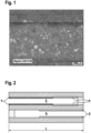
- the Fig. 1 shows a light microscopy image of a filter coated with powder.
- the photo shows a top view of several channel walls in an area of the filter where there is no catalytically active on-wall layer.
- the powder selectively deposits itself in the pores of the wall and fills them.
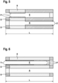
- Fig. 2 shows schematically a filter not according to the invention, which has a zone of an on-wall layer on the inlet (Y) and outlet side (Z) with a zone length of approximately 60% of the total length and is charged with powder (P) at the end in the uncoated part of the inlet channel (E).
- Fig. 3 shows the same, non-inventive construction of the filter as Fig. 2 with the difference that the two on-wall layers (X, Y) have a coating gradient from the end faces to the center of the beam.
- Fig. 4 shows a filter not according to the invention with an on-wall layer (X) in the inlet area E, which is charged with a powder (P) in the inlet channel (E).
- Fig. 5 shows a filter not according to the invention with an on-wall layer (Z) in the outlet area A and a zone with an in-wall coating (X), in which the powder (P) is deposited in the area of highest permeability.
- Fig. 6 shows a filter not according to the invention in which the walls of the channels are completely activated with an in-wall coating (X) and which has a zone with an on-wall layer (Y) on the inlet side (E) and has been charged with powder (P).
- Fig. 7 shows the same filter as Fig. 5 but without catalytically active in-wall coating (X).
- Fig. 8 shows schematically a filter not according to the invention with one on-wall layer each in the inlet (Y) and outlet channel (Z) with a length of approximately 30% of the total length L and an area in the inlet channel (E) loaded with powder (P).
- Fig. 9 shows the results of the investigations into the filtration efficiency of all particle filters described here and particle filters according to the state of the art.
- Fig. 10 shows a photo of an opened filter with a zone of an on-wall layer in the inlet channels (grey, left side) and the area loaded with powder (right side) - not according to the invention
- Fig. 11 shows enlargements of the filter Fig. 10 with photos of the entrance (1), the middle (2) and the exit (3) of the filter
- Fig. 12 shows a schematic drawing of an advantageous device for applying a powder to the filters.
- the powder 420 or 421 is mixed with the pressurized gas 451 through the atomizer nozzle 440 in the mixing chamber with the gas stream 454 and then sucked or forced through the filter 430.
- the particles that pass through are filtered out in the exhaust filter 400.
- the blower 410 ensures the necessary volume flow.
- the exhaust gas is divided into an exhaust gas 452 and a warm recycle gas 453.
- the warm recycle gas 453 is mixed with the fresh gas 450.
- the wall-flow filter substrates had a cell density of 46.5 cells per square centimeter and a cell wall thickness of 0.22 mm. They exhibited a porosity of 65% and an average pore size of 18 ⁇ m.
- Comparative Example 1 a coating suspension was applied to the outflow channels.
- Comparative Example 2 coating suspensions were applied in two steps to the inflow and outflow channels.
- the filter described in Comparative Example 3 contains both a coating arranged in the wall and a coating suspension applied to the inflow channels. After application of each coating suspension, the wall-flow filters were dried and calcined at 500°C for a period of 4 hours.
- the coating suspension was applied according to the instructions of the person skilled in the art (as described in DE102010007499A1 described)
- the resulting catalytically active filters were tested for their fresh filtration efficiency on an engine test bench in the real exhaust gas of an engine operating predominantly (>50% of operating time) and on average (average lambda over the running time) with a stoichiometric air/fuel mixture.
- a globally standardized test procedure for determining exhaust emissions known as WLTP (Worldwide Harmonized Light Vehicles Test Procedure), was applied.
- the driving cycle used was WLTC Class 3.
- Each filter was installed close to the engine directly downstream of a conventional three-way catalytic converter. This three-way catalytic converter was the same for all filters tested.
- Each filter was subjected to a WLTP test. To detect particulate emissions during testing, particle counters were installed upstream of the three-way catalytic converter and downstream of the particulate filter.
- Some catalytically active particulate filters were also subjected to engine test bench aging.
- the aging consisted of overrun cut-off aging with Exhaust gas temperature before the catalyst inlet was 950°C (maximum bed temperature 1030°C). The aging time was 38 hours. After aging, the filters were tested for their catalytic activity.
- a noble metal-containing coating suspension containing a cerium/zirconium mixed oxide, a lanthanum-doped aluminum oxide, and barium sulfate was applied to 80% of the length of the filter outlet channel on wall-flow filters with a diameter of 118 mm and a length of 152 mm.
- the coating suspension was subsequently calcined at 500°C.
- the grain size of the oxides in the coating suspension was selected so that the suspension was predominantly applied to the filter wall (only a small amount of the finest fraction of the coating particles penetrated the wall pores; less than 10%).
- the coating quantity of VGPF1 after calcination corresponded to 67 g/l, based on the substrate volume.
- a noble metal-containing coating suspension containing a cerium/zirconium mixed oxide, a lanthanum-doped aluminum oxide, and barium sulfate was applied to a wall-flow filter with a diameter of 118 mm and a length of 118 mm. The coating suspension was then calcined over 60% of the length of the inlet channel. In a second coating step, another noble metal-containing coating suspension was applied over 60% of the length of the outlet channel and then calcined. The coating suspension used in the second coating step also contained a cerium/zirconium mixed oxide, a lanthanum-doped aluminum oxide, and barium sulfate. The grain size of the oxides in the coating suspension was selected so that the suspension was applied predominantly to the filter wall. The coating quantity of VGPF2 after calcination corresponded to 100 g/l, based on the substrate volume.
- a precious metal-containing coating suspension containing a cerium/zirconium mixed oxide, a lanthanum-doped aluminum oxide, and barium sulfate was applied to the entire length of a highly porous wall-flow filter with a diameter of 132 mm and a length of 102 mm.
- the coating was then calcined.
- the grain size of the oxides in the coating suspension was selected so that the suspension was predominantly located in the filter wall (>90%).
- the coating quantity after calcination corresponded to 100 g/l, based on the substrate volume.
- a second coating step another precious metal-containing coating suspension was applied to 60% of the inlet channel and subsequently calcined.
- the coating suspension used in the second coating step also contained a cerium/zirconium mixed oxide, a lanthanum-doped aluminum oxide, and barium sulfate.
- the grain size of the oxides in the coating suspension was selected so that the suspension was applied predominantly to the filter wall.
- the coating quantity of VGPF3 after calcination corresponded to 132 g/l, based on the substrate volume.
- Example 1 (according to the invention):
- the inflow channels of the filter were charged with 4 g/l of a highly porous aluminum oxide.
- the relative increase in back pressure of the GPF1 compared to the VGPF1 was 8.6 mbar.
- the GPF1 filter described in Example 1 is Fig. 7 outlined.
- the inflow channels of the filter were charged with 0.2 g/l of a high-melting pyrogenic aluminum oxide.
- the relative increase in back pressure of the GPF1 compared to the VGPF1 was 5 mbar.
- the filter GPF2 described in Example 2 is Fig. 7 outlined.
- the inflow channels of the filter were charged with 10 g/l of a highly porous aluminum oxide.
- the filter GPF3 described in Example 3 is Fig. 2 outlined.
- the inflow channels of the filter were charged with 4 g/l of a highly porous aluminum oxide.
- the filter GPF4 described in Example 4 is Fig. 4 outlined.
- the inflow channels of the filter were charged with 7 g/l of a highly porous aluminum oxide.
- the filter GPF5 described in Example 5 is Fig. 4 outlined.
- Fig. 9 shows filtration values resulting from the raw particle emissions and particle emissions after the respective filter during a WLTP procedure.
- the non-inventive particulate filters GPF4 and GPF5 were subjected to engine test bench aging and a subsequent measurement of the light-off behavior.
- Table 1 contains the light-off data for the aged filters VGPF3, GPF4, and GPF5.
- Table 1 T 50 HC stoch T 50 CO stoch T 50 NOx stoch VGPF3 381 398 395 GPF4 386 401 401 GPF5 383 401 402
Landscapes
- Chemical & Material Sciences (AREA)
- Engineering & Computer Science (AREA)
- Chemical Kinetics & Catalysis (AREA)
- Physics & Mathematics (AREA)
- Geometry (AREA)
- Mechanical Engineering (AREA)
- Combustion & Propulsion (AREA)
- General Engineering & Computer Science (AREA)
- Organic Chemistry (AREA)
- Materials Engineering (AREA)
- Ceramic Engineering (AREA)
- Manufacturing & Machinery (AREA)
- Structural Engineering (AREA)
- Catalysts (AREA)
- Filtering Materials (AREA)
- Exhaust Gas Treatment By Means Of Catalyst (AREA)
Description
- Die vorliegende Erfindung ist auf ein Verfahren zur Herstellung eines Wandflussfilters zur Minderung schädlicher Abgase und feiner Partikel eines Verbrennungsmotors gerichtet.
- Zur Entfernung der Partikelemissionen und Reduzierung der Schadstoffe in Abgasen sind Dieselpartikelfilter bzw. Benzinpartikelfilter mit und ohne zusätzliche katalytisch aktive Beschichtung geeignete Aggregate. Dies sind Wandflusswabenkörper, die als Katalysatorträger, Träger oder Substratmonolithe bezeichnet werden. Zur Erfüllung der gesetzlichen Normen ist es für die aktuellen und zukünftigen Applikationen zur Abgasnachbehandlung von Verbrennungsmotoren aus Kostengründen aber auch aus Bauraumgründen wünschenswert, Partikelfilter mit anderen katalytisch aktiven Funktionalitäten zu kombinieren. Die katalytisch aktive Beschichtung kann sich dabei auf der Oberfläche bzw. in den diese Oberfläche bildenden Wänden der Kanäle befinden. Die katalytisch aktive Beschichtung wird häufig in einem sogenannten Beschichtungsvorgang in Form einer Suspension auf den Katalysatorträger aufgebracht. Viele derartige Prozesse sind in der Vergangenheit von Autoabgaskatalysatorherstellern hierzu veröffentlicht worden (
EP1064094B1 ,EP2521618B1 ,WO10015573A2 EP1136462B1 ,US6478874B1 ,US4609563A ,WO9947260A1 JP5378659B2 EP2415522A1 ,JP2014205108A2 - Es hat schon einige Anstrengungen gegeben, Partikelfilter bereitzustellen, die eine gute katalytische Aktivität durch eine aktive Beschichtung aufweisen und einen dennoch möglichst geringen Abgasgegendruck zeigen. Im Hinblick auf einen niedrigen Abgasgegendruck hat es sich als günstig erwiesen, wenn die katalytisch aktive Beschichtung nicht als Schicht auf den Kanalwänden eines porösen Wandflussfilters befindlich ist, sondern die Kanalwände des Filters mit dem katalytisch aktiven Material durchsetzt sind (
WO2005016497A1 , JPH01-151706,EP1789190B1 ). Hierfür wird die Partikelgröße der katalytischen Beschichtung so gewählt, dass die Partikel in die Poren der Wandflussfilter eindringen und dort durch Kalzinieren fixiert werden können. Nachteilig an katalytisch aktiven Filtern mit einer In-Wand-Beschichtung ist, dass die Menge an katalytisch wirksamer Substanz durch das Aufnahmevermögen der porösen Wand begrenzt ist. - Es hat sich gezeigt, dass durch Aufbringen der katalytisch aktiven Substanzen auf die Oberflächen der Kanalwände eines Wandflusswabenkörpers eine Erhöhung der Umsetzung der Schadstoffe im Abgas erzielt werden kann. Auch Kombinationen von Aufwand- und In-Wand-Beschichtung mit katalytisch aktivem Material sind möglich, wodurch die katalytische Performance weiter gesteigert werden kann, ohne dass sich der Staudruck wesentlich erhöht (
WO2018172299A1 ;WO2015082892A2 ). - Neben der katalytischen Wirksamkeit ist eine weitere Funktionalität des Filters, die durch eine Beschichtung verbessert werden kann, seine Filtrationseffizienz, also die Filterwirkung selbst. Spezielle naßtechnisch aufgebrachte Filtrationsbeschichtungen werden z.B. in der
EP2832962A1 erwähnt. - In der
WO2011151711A1 wird eine Methode beschrieben, mit der ein nicht beschichteter oder katalytisch beschichteter Filter, der das katalytische aktive Material in den Kanalwänden trägt (In-Wand-Beschichtung mit Washcoat) mit einem trockenen Aerosol beaufschlagt wird. Das Aerosol wird durch die Verteilung eines pulverförmigen hochschmelzenden Metalloxids bereitgestellt und mittels eines Gasstroms über die Einlassseite eines Wandflussfilters geführt. Hierbei agglomerieren die einzelnen Partikel mit einer Partikelgröße von 0,2 µm bis 5 µm zu einem verbrückten Netzwerk an Partikeln und werden als Schicht auf der Oberfläche der einzelnen den Wandflussfilter durchziehenden Einlasskanäle abgeschieden. Die typische Beladung eines Filters mit dem Pulver beträgt zwischen 5 g und 50 g pro Liter Filtervolumen. Es wird ausdrücklich darauf hingewiesen, dass es nicht erwünscht ist, mit dem Metalloxid eine Beschichtung in den Poren des Wandflussfilters zu erreichen. - Eine weitere Methode zur Erhöhung der Filtrationseffizienz von katalytisch nicht aktiven Filtern wird in der
WO2012030534A1 beschrieben. Hierbei wird auf den Wänden der Strömungskanäle der Einlassseite eine Filtrationsschicht ("discriminating layer") durch Ablagerung von keramischen Partikel über ein Partikelaerosol erzeugt. Die Schichten bestehen aus Oxiden von Zirkon, Aluminium oder Silicium, bevorzugt in Faserform von 1 nm bis 5 µm und haben eine Schichtdicke von mehr als 10 µm, in der Regel 25 µm bis 75 µm. Nach dem Beschichtungsprozess werden die aufgetragenen Pulverpartikel in einem Wärmeprozess kalziniert. - Ein weiteres Verfahren bei dem zur Erhöhung der Filtrationseffizienz von katalytisch nicht aktiven Wandflussfiltern eine Membran ("trapping layer") auf den Oberflächen der Einlasskanäle von Filtern erzeugt wird, ist in der
Patentschrift US8277880B2 beschrieben. Die Filtrationsmembran auf den Oberflächen der Einlasskanäle wird durch Durchsaugen eines mit Keramikpartikeln (z. B. Siliciumcarbid, Cordierit) beladenen Gasstroms realisiert. Der Wabenkörper wird nach dem Aufbringen der Filterschicht bei Temperaturen von größer 1000°C gebrannt um die Haftfestigkeit der Pulverschicht auf den Kanalwänden zu erhöhen. InEP2502661A2 undEP2502662B1 werden weitere Aufwandbeschichtungen durch Pulverapplikation erwähnt. - Eine Beschichtung innerhalb der Poren eines Wandflussfilteraggregats mittels Verdüsung von trockenen Partikeln wird in der
US8388721B2 beschrieben. Hier soll allerdings das Pulver tief in die Poren eindringen. 20 % bis 60 % der Oberfläche der Wand soll für Rußpartikel zugänglich, demnach offenbleiben. Abhängig von der Strömungsgeschwindigkeit des Pulver-Gas-Gemisches kann ein mehr oder minder starker Pulvergradient zwischen Einlass- und Auslassseite eingestellt werden. Die Poren der Kanalwände des nachUS8388721B2 mit Pulver in den Poren beschichteten Filters können nachträglich mit einer katalytisch aktiven Komponente beschichtet werden. Auch hier befindet sich das katalytisch aktive Material in den Kanalwänden des Filters. - Ebenfalls wird die Einbringung des Pulvers in die Poren, z. B. mithilfe eines Aerosolgenerators, in der
EP2727640A1 beschrieben. Hier wird ein nicht katalytisch beschichteter Wandflussfilter mit einem z. B. Aluminiumoxidpartikel enthaltenden Gasstroms dergestalt beschichtet, dass die kompletten Partikel, die eine Partikelgröße von 0,1 µm bis 5 µm aufweisen, als poröse Füllung in den Poren des Wandflussfilters abgeschieden werden. Die Partikel selber können eine weitere Funktionalität des Filters zusätzlich zu der Filterwirkung realisieren. Beispielhaft werden diese Partikel in einer Menge von mehr als 80 g/l bezogen auf das Filtervolumen in den Poren des Filters abgeschieden. Sie füllen dabei 10 % bis 50 % des Volumens der gefüllten Poren in den Kanalwänden aus. Dieser Filter weist sowohl mit Ruß beladen wie auch ohne Ruß eine gegenüber dem unbehandelten Filter verbesserte Filtrationseffizienz bei einem geringeren Abgasgegendruck des mit Ruß beladenen Filters auf. - In der
WO2018115900A1 werden Wandflussfilter mit einer ggf. trockenen synthetischen Asche dergestalt beschichtet, dass eine kontinuierliche Membranschicht auf den Wänden des ggf. katalytisch beschichteten Wandflussfilters entsteht. - Alle in diesem Stand der Technik aufgeführten Patente haben das Ziel, die Filtrationseffizienz eines Filters durch eine Belegung des Filters mit einem Pulver zu erhöhen. Die derart hinsichtlich Filtrationseffizienz optimierten Filter können auch vor der Pulverbeschichtung eine katalytisch aktive Beschichtung in den porösen Kanalwänden tragen. In keinem der Beispiele finden sich jedoch Hinweise darauf, gleichzeitig die katalytische Wirkung eines Filters und die Erhöhung der Filtrationseffizienz zu optimieren. Es besteht daher weiterhin Bedarf an Partikelfiltern, bei denen sowohl die katalytische Aktivität und die Filtrationseffizienz im Hinblick auf den Abgasgegendruck optimiert sind.
- Aufgabe der vorliegenden Erfindung ist es, einen entsprechenden Partikelfilter anzugeben, bei dem eine ausreichende Filtrationseffizienz mit einer möglichst geringen Erhöhung des Abgasgegendrucks und einer hohen katalytischen Aktivität gekoppelt ist.
- Diese und weitere sich aus dem Stand der Technik in naheliegender Weise ergebenden Aufgaben werden durch die Angabe eines Partikelfilters gemäß den Ansprüchen erfüllt.
- Die vorliegende Erfindung bezieht sich auf einVerfahren zur Herstellung eines Wandflussfilters zur Entfernung von Partikeln aus dem Abgas von Verbrennungsmotoren gemäß Anspruch 1. Durch die Beaufschlagung eines in konventioneller Art nasstechnisch zoniert beschichteten Wandflussfilters, bei dem sich die katalytisch aktive Beschichtung auf der Oberfläche der Kanalwand befindet und den man nach dem Trocknen und/oder Kalzinieren mit einem trockenen Pulvergasaerosol beschichtet, erhält man einen Wandflussfilter mit überaus guter Filtrationseffizienz und nur wenig erhöhtem Abgasgegendruck und gleichzeitig hervorragender katalytischer Wirksamkeit.
- Die hier beschriebenen katalytisch beschichteten und anschließend mit Pulver beaufschlagten Filter unterscheiden sich von denen, die im Abgasstrang eines Fahrzeugs durch Ascheablagerung während des Betriebs entstehen. Erfindungsgemäß werden die katalytisch aktiven Filter gezielt mit einem bestimmten, trockenen Pulver bestäubt. Dies führt dazu, dass die Balance zwischen Filtrationseffizienz und Abgasgegendruck von Anfang an gezielt eingestellt werden kann. Nicht mitumfasst von der vorliegenden Erfindung sind daher Wandflussfilter, bei denen undefinierte Ascheablagerungen aus der Verbrennung von Kraftstoff z.B. im Zylinder während des Fahrbetriebs oder mittels eines Brenners erfolgt sind.
- Als Wandflussmonolithe oder Wandflussfilter können alle im Stand der Technik üblichen keramischen Materialien eingesetzt werden. Bevorzugt werden poröse Wandflussfiltersubstrate aus Cordierit, Siliziumcarbid oder Aluminiumtitanat eingesetzt. Diese Wandflussfiltersubstrate weisen An- und Abströmkanäle auf, wobei jeweils die abströmseitigen Enden der Anströmkanäle und die anströmseitigen Enden der Abströmkanäle gegeneinander versetzt mit gasdichten "Stopfen" verschlossen sind. Hierbei wird das zu reinigende Abgas, das das Filtersubstrat durchströmt, zum Durchtritt durch die poröse Wand zwischen An- und Abströmkanal gezwungen, was eine Partikelfilterwirkung bedingt. Durch die Porosität, Poren-/Radienverteilung, und Dicke der Wand kann die Filtrationseigenschaft für Partikel ausgelegt werden. Die Porosität der unbeschichteten Wandflussfilter beträgt in der Regel mehr als 40 %, generell von 40 % bis 75 %, besonders von 50 % bis 70 % [gemessen nach DIN 66133 - neueste Fassung am Anmeldetag]. Die durchschnittliche Porengröße der unbeschichteten Filter beträgt wenigstens 7 µm, z. B. von 7 µm bis 34 µm, bevorzugt mehr als 10 µm, insbesondere mehr bevorzugt von 10 µm bis 25 µm oder ganz bevorzugt von 15 µm bis 20 µm [gemessen nach DIN 66134 neueste Fassung am Anmeldetag]. Die fertiggestellten Filter (katalytisch beschichtet) mit einer Porengröße von in der Regel 10 µm bis 20 µm und einer Porosität von 50 % bis 65 % sind besonders bevorzugt.
- Die katalytische Beschichtung Z des mit dem Pulver zu beaufschlagenden Wandflussfilters erstreckt sich nicht über die gesamte Länge des Wandflussfilters. Die Beschichtung Z befindet sich ausgehend vom jeweiligen Ende des Wandflussfilters auf einer Länge von 10 bis zu 90 % der Länge L. Die minimale Länge der Beschichtung Z beträgt mindestens 1,25 cm, vorzugsweise mindestens 2,0 cm und ganz bevorzugt mindestens 2,5 cm vom jeweiligen Ende des Filters gerechnet. Die Beschichtung Z befindet sich auf der Oberfläche OA. Diese so genannten Aufwandbeschichtung beträgt vom jeweiligen Ende des Wandflussfilters gerechnet 10 bis 90 % der Länge L des Wandflussfilters, vorzugsweise 30 bis 80 % und besonders bevorzugt 60 bis 80%. Unter Aufwandbeschichtung ist gemeint, dass diese Beschichtung sich über die Oberfläche OA, in den Kanal A des Wandflussfilters erhebt, den Kanalquerschnitt mithin erniedrigen. Nur untergeordnet werden die oberflächlich liegenden Poren der Oberfläche OA, mit dem katalytisch aktiven Material gefüllt. Mehr als 80 %, bevorzugt mehr als 90 % des katalytisch aktiven Materials befindet sich nicht in der porösen Wand des Kanals A.
- In einer weiter bevorzugten Ausführungsform weist die Beschichtung Z einen Dickegradienten über die Länge L dergestalt auf, dass an den jeweiligen Enden des Wandflussfilters die geringste Dicke der Beschichtung Z vorherrscht. Die Dicke wächst mithin entlang der Länge L des Wandflussfilters (siehe
Fig. 3 ) Dabei kann es sein, dass diese Beschichtung vorzugsweise mehr als 2-mal, mehr bevorzugt bis zu mehr als 3-mal die Dicke an einem Beschichtungsende aufweist wie am anderen Beschichtungsende. Die Dicke ist dabei die Höhe, mit der sich die Beschichtung Z über die Oberfläche OA, erhebt. Durch den Dickegradienten der Beschichtung auf der Kanalwand erreicht man zudem, dass sich die Filtrationseffizienz über die gesamte Länge L des Filters angleicht. Eine gleichmäßigere Abscheidung des Rußes über die gesamte Filterwand und damit ein verbesserter Abgasgegendruckanstieg und ggf. ein besserer Abbrand des Rußes sind das Resultat. - Der Wandflussfilter, welcher erfindungsgemäß mit dem Pulvergasaerosol beaufschlagt wird, trägt demgemäß eine katalytische Aktivität (hier mit Z bezeichnet) bereits in sich. Unter katalytischer Aktivität wird vorliegend die Fähigkeit verstanden, schädlich Bestandteile des Abgases von Verbrennungsmotoren in weniger schädliche zu verwandeln. Insbesondere sind hier die Abgasbestandteile NOx, CO und HC oder der Partikelabbrand zu nennen. Diese katalytische Aktivität wird nach Maßgabe des Fachmanns durch eine Beschichtung des Wandflussfilters in dessen Wände und/oder auf dessen Wände mit einem katalytisch aktiven Material bereitgestellt. Unter dem Begriff des Beschichtens wird demgemäß das Aufbringen von katalytisch aktiven Materialien auf einen Wandflussfilter verstanden. Die Beschichtung übernimmt die eigentliche katalytische Funktion. Vorliegend erfolgt die Beschichtung durch das Aufbringen einer entsprechend wenig viskosen wässrigen Suspension der katalytisch aktiven Komponenten - auch Washcoat genannt - in oder auf die Wand des Wandflussfilters, z. B. gemäß
EP1789190B1 . Nach dem Aufbringen der Suspension wird der Wandflussfilter getrocknet und gegebenenfalls bei erhöhter Temperatur kalziniert. Der katalytisch beschichtete Filter besitzt eine Beladung von 20 g/l bis 200 g/l, vorzugsweise 30 g/l bis 150 g/l. Die geeignetste Beladungsmenge eines in der Wand beschichteten Filters hängt von seiner Zelldichte, seiner Wandstärke und der Porosität ab. - Im Prinzip sind alle dem Fachmann für den Autoabgasbereich bekannten Beschichtungen sowie Kombination derer für die vorliegende Erfindung geeignet. Die katalytische Beschichtung des Filters kann bevorzugt aus der Gruppe bestehend aus Dreiwegkatalysator, SCR-Katalysator, Stickoxidspeicherkatalysator, Oxidationskatalysator, Rußabbrandbeschichtung ausgewählt werden. Hinsichtlich der einzelnen in Frage kommenden katalytischen Funktionen und deren Erklärung wird auf die Ausführungen in der
WO2011151711A1 verwiesen. - Besonders bevorzugt sind Beschichtungen, die eine Dreiwegefunktionalität besitzen und insbesondere bei Betriebstemperaturen von 250 bis 1100 °C aktiv sind. Sie enthalten üblicherweise ein oder mehrere Edelmetalle, die auf einem oder mehreren Trägermaterialien fixiert sind, sowie ein oder mehrere Sauerstoffspeicherkomponenten. Als Edelmetalle kommen insbesondere Platin, Palladium und Rhodium in Frage, wobei Palladium, Rhodium oder Palladium und Rhodium bevorzugt und Palladium und Rhodium besonders bevorzugt sind. Bezogen auf das erfindungsgemäße Partikelfilter ist der Anteil von Rhodium am gesamten Edelmetallgehalt insbesondere größer oder gleich 10 Gew.-%. Die Edelmetalle werden üblicherweise in Mengen von 0,15 bis 5 g/l, bezogen auf das Volumen des Wandflussfilters eingesetzt.
- Als Trägermaterialien für die Edelmetalle kommen alle dem Fachmann für diesen Zweck geläufigen Materialien in Betracht. Solche Materialien sind insbesondere Metalloxide mit einer BET-Oberfläche von 30 bis 250 m2/g, bevorzugt von 100 bis 200 m2/g (bestimmt nach DIN 66132 - neueste Fassung am Anmeldetag). Besonders geeignete Trägermaterialien für die Edelmetalle sind ausgewählt aus der Reihe bestehend aus Aluminiumoxid, dotiertes Aluminiumoxid, Siliziumoxid, Titandioxid und Mischoxiden aus einem oder mehreren davon. Dotierte Aluminiumoxide sind beispielsweise Lanthanoxid-, Zirkoniumoxid- und/oder Titanoxid-dotierte Aluminiumoxide. Mit Vorteil wird Lanthan-stabilisiertes Aluminiumoxid eingesetzt, wobei Lanthan in Mengen von 1 bis 10 Gew.-%, bevorzugt 3 bis 6 Gew.-%, jeweils berechnet als La2O3 und bezogen auf das Gewicht des stabilisierten Aluminiumoxides, verwendet wird. Ein weiteres geeignetes Trägermaterial ist Lanthan-stabilisiertes Aluminiumoxid, dessen Oberfläche mit Lanthanoxid, mit Bariumoxid oder mit Strontiumoxid beschichtet ist.
- Als Sauerstoffspeicherkomponente kommen insbesondere Cer/Zirkonium/Seltenerdmetall-Mischoxide in Frage. Der Begriff "Cer/Zirkonium/Seltenerdmetall-Mischoxid" im Sinne vorliegender Erfindung schließt physikalische Mischungen aus Ceroxid, Zirkoniumoxid und Seltenerdoxid aus. Vielmehr sind "Cer/Zirkonium/Seltenerdmetall-Mischoxide" durch eine weitgehend homogene, dreidimensionale Kristallstruktur gekennzeichnet, die idealerweise frei ist von Phasen aus reinem Ceroxid, Zirkoniumoxid bzw. Seltenerdoxid (feste Lösung). Je nach Herstellungsverfahren können aber auch nicht vollständig homogene Produkte entstehen, die in der Regel ohne Nachteil verwendet werden können. Im Übrigen umfasst der Begriff Seltenerdmetall bzw. Seltenerdmetalloxid im Sinne vorliegender Erfindung kein Cer bzw. kein Ceroxid. Als Seltenerdmetalloxide in den Cer/Zirkonium/Seltenerdmetall-Mischoxiden kommen beispielsweise Lanthanoxid, Yttriumoxid, Praseodymoxid, Neodymoxid und/oder Samariumoxid in Betracht. Bevorzugt sind Lanthanoxid, Yttriumoxid und/oder Praseodymoxid. Besonders bevorzugt sind Lanthanoxid und/oder Yttriumoxid und ganz besonders bevorzugt sind Lanthanoxid und Yttriumoxid, Yttriumoxid und Praseodymoxid, sowie Lanthanoxid und Praseodymoxid. In Ausführungsformen der vorliegenden Erfindung sind die Sauerstoffspeicherkomponenten frei von Neodymoxid. Erfindungsgemäß kann das Masseverhältnis von Ceroxid zu Zirkoniumoxid in den Cer/Zirkonium/Seltenerdmetall-Mischoxiden in weiten Grenzen variieren. Es beträgt beispielsweise 0,1 bis 1,5, bevorzugt 0,2 bis 1 oder 0,3 bis 0,5.
- Sofern die Cer/Zirkonium/Seltenerdmetall-Mischoxide als Seltenerdmetall Yttriumoxid enthalten, so ist dessen Anteil insbesondere 5 bis 15 Gew.-% bezogen auf das Sauerstoffspeichermaterial. Sofern die Cer/Zirkonium/Seltenerdmetall-Mischoxide als Seltenerdmetall Praseodymoxid enthalten, so ist dessen Anteil insbesondere 2 bis 10 Gew.-% bezogen auf das Sauerstoffspeichermaterial. Sofern die Cer/Zirkonium/Seltenerdmetall-Mischoxide als Seltenerdmetall Lanthanoxid und Yttriumoxid enthalten, so ist dessen Massenverhältnis insbesondere 0,1 bis 1. Sofern die Cer/Zirkonium/Seltenerdmetall-Mischoxide als Seltenerdmetall Lanthanoxid und Praseodymoxid enthalten, so ist dessen Massenverhältnis insbesondere 0,1 bis 1. Üblicherweise enthalten die Beschichtungen Y, Y' und Z Sauerstoffspeicherkomponenten in Mengen von 15 bis 120 g/l, bezogen auf das Volumen des Wandflussfilters. Das Masseverhältnis von Trägermaterialien und Sauerstoffspeicher-komponenten in der Beschichtung Z beträgt üblicherweise 0,3 bis 1,5, beispielsweise 0,4 bis 1,3.
- In Ausführungsformen der vorliegenden Erfindung umfasst die Beschichtung Z Lanthan-stabilisiertes Aluminiumoxid, Rhodium, Palladium oder Palladium und Rhodium und eine Zirkoniumoxid, Ceroxid, Yttriumoxid und Lanthanoxid aufweisende Sauerstoffspeicher-komponente. In anderen Ausführungsformen der vorliegenden Erfindung umfasst die Beschichtung Z Lanthan-stabilisiertes Aluminiumoxid, Rhodium, Palladium oder Palladium und Rhodium und eine Zirkoniumoxid, Ceroxid, Praseodymoxid und Lanthanoxid umfassende Sauerstoffspeicherkomponente.
- In Ausführungsformen der vorliegenden Erfindung enthält die Beschichtung Z keinen Zeolithen und kein Molsieb.
- Die Zusammensetzung der jeweiligen Beschichtung sowie der Beschichtungsart (auf der Wand), sowie die Menge der aufgebrachten katalytischen Beschichtung kann hinsichtlich der gewünschten katalytischen Aktivität variiert und kombiniert werden. Durch die oben beschriebene Variation der katalytisch aktiven Beschichtung werden im Filter unterschiedliche Wandpermeabilitäten geschaffen. Zusätzlich weisen produktionsbedingt die katalytischen Schichten auf den Filterwänden manchmal Inhomogenitäten, kleine Risse, unterschiedliche Schichtdicken sowie teilweise auch unbeschichtete Fehlstellen auf und zeigen zwar eine hohe katalytische Aktivität und einen akzeptablen Gegendruck auf, haben aber eine relativ niedrige Frischfiltrationseffizienz. Auch die Bereiche, die keine katalytische Beschichtung aufweisen, weisen ggf. eine geringere Filtrationseffizienz auf. All dies führt dazu, dass die Kanalwände unterschiedlich gut gasdurchlässig sind und Bereiche mit unterschiedlicher Gaspermeabilität aufweisen können.
- Das Beaufschlagen des hier betrachteten Wandflussfilters mit dem trockenen Pulvergasaerosol führt also dazu, dass sich die Pulverteilchen dem Strom des Gases folgend in den Poren des Filters abscheiden. Dabei führt die zuvor erwähnte unterschiedliche Wandpermeabilität des Filters (z.B. bedingt durch Inhomogenitäten der Filterwand selbst oder unterschiedliche Beschichtungszonen) zu einer selektiven Abscheidung des Pulvers auf der Filterwand oder in den Poren der Wand dort, wo die Strömung am größten ist. Dieser Effekt führt auch dazu, dass zum Beispiel Risse oder Poren in der Washcoatschicht aufgrund von Beschichtungsfehlern durch das poröse Pulver so aufgefüllt werden, dass späterhin die Rußpartikel im Abgas beim Durchgang des Abgases durch den Filter vermehrt zurückgehalten werden. Eine bessere Filtrationseffizienz ist mithin die Folge.
- Erfindungsgemäß wird demnach der zoniert beschichtete, trockene Abgasfilter in Abgasströmungsrichtung mit einem Pulver derart belegt, dass die am stärksten durchströmten Zellwandbereiche mit lockeren in sich porösen Pulveranhäufungen in den Poren und ggf. auch auf der Wand belegt werden, um eine gewünschte erhöhte Filtrationseffizienz zu erhalten. Dabei führt die Bildung der in sich porösen Pulveranhäufungen überraschenderweise zu einer relativ niedrigen Staudruckerhöhung. In einer bevorzugten Ausführungsform wird der Wandflussfilter so mit einem Pulvergasaerosol beaufschlagt, dass sich das Pulver bei der Beaufschlagung auf den Kanalwänden der Eingangsseite abscheidet und hier eine zusammenhängende Schicht aufbaut. In einer weiterhin ganz bevorzugten Ausführungsform wird der Wandflussfilter so mit einem Pulvergasaerosol beaufschlagt, dass sich das Pulver bei der Beaufschlagung in den Poren der Filterwände niederschlägt und diese bis zur Eingangsoberfläche auffüllt und dabei keine zusammenhängende Schicht auf den Wänden des Filters ausbildet.
- Die Menge des verwendeten Pulvers hängt von der Art des Pulvers, Art der Beschichtung (siehe eben) und ggf. dem Volumen der zur Verfügung stehenden Poren ab und kann unter den gegebenen Randbedingungen (nicht zu hoher Abgasgegendruck) vom Fachmann in vorläufigen Versuchen bestimmt werden. In der Regel liegt die Beladung des Filters mit dem Pulver bei nicht mehr als 50 g/l bezogen auf das Filtervolumen. Bevorzugt beträgt der Wert nicht mehr als 20 g/l, ganz besonders bevorzugt nicht mehr als 10 g/l. Eine untere Grenze bildet naturgemäß die angestrebte Erhöhung der Filtrationseffizienz. Die genaue Menge an benötigtem Pulver zur Steigerung der Filtrationseffizienz wird in Abhängigkeit der Länge und der Art der katalytischen Beschichtung bestimmt. Sofern nur eine Pulverbeschichtung in den Oberflächenporen des Filters angestrebt wird, reicht eine Menge unter den genannten Voraussetzungen vorteilhaft eine Menge an Pulver von bis zu 10 g/l, bevorzugt bis zu 5 g/l aus.
- Pulver, welche bevorzugt in der vorliegenden Erfindung zur Erzeugung des Aerosols herangezogen werden, sind dem Fachmann hinlänglich bekannt. Es sind dies hochschmelzende Metallverbindungen, die gemeinhin als Trägermaterialien für Katalysatoren im Autoabgasbereich herangezogen werden. Bevorzugt werden entsprechende Metalloxid-, Metallsulfat-, Metallphosphat-, Metallcarbonat- oder Metallhydroxidpulver oder deren Mischungen eingesetzt. Die für die Metallverbindungen infrage kommenden Metalle sind insbesondere solche ausgewählt aus der Gruppe der Alkali-, Erdalkali- bzw. Erdmetalle oder Übergangsmetalle. Bevorzugt werden solche Metalle ausgewählt aus der Gruppe Calcium, Magnesium, Strontium, Barium, Aluminium, Silizium, Titan, Zirkon, Cer eingesetzt. Diese Metalle können vorzugsweise wie gesagt als Oxide eingesetzt werden. Ganz besonders bevorzugt ist der Einsatz von Ceroxid, Titandioxid, Zirkondioxid, Siliziumdioxid, Aluminiumoxid, Eisenoxid, Zinkoxid oder Mischungen oder Mischoxiden derselben. Ganz besonders bevorzugt ist der Einsatz von einem Aerosol, welches ein Gemisch aus Luft und einem dieser Metalloxidpulver darstellt. Unter dem Begriff Mischoxid (feste Lösungen von einem Metalloxid in mindestens einem anderen) wird vorliegend auch der Einsatz von Zeolithen und Zeotypen verstanden. Im Rahmen der Erfindung sind Zeolithe und Zeotype definiert wie in der
WO2015049110A1 . - Neben den üblicherweise chemisch gefällten Metalloxiden können auch sogenannte pyrogene Metalloxidpulver verwendet werden. Allgemein versteht man unter pyrogen hergestellten Metalloxidpulvern solche, die durch eine Flammenhydrolyse oder Flammenoxidation aus einem Metalloxidprecursor in einer Knallgasflamme erhalten werden (https://de.wikipedia.org/w/index.php?title=Pyrogenes Siliciumdioxid&oldid=182147815; Pater Albers et al. Chemie in unserer Zeit, 2016, 50, 162 - 171; Hans Ferkel et al. MTZ - Motortechnische Zeitschrift, 2010, 71, 128 - 133). Diese weisen Eigenschaften auf, wie sie für flammensynthetisierte partikuläre Produkte in folgenden Literaturstellen beschrieben werden, Gutsch A. et al. (2002) KONA (No. 20); Li S. et al. (2016) Progress in Energy and Combustion Science (55); Ulrich G. (1971) Combustion Science and Technology (Vol. 4). Pyrogene Metalloxide zeichnen sich in der Regel durch eine hohe spezifische Oberfläche und eine geringe Schüttdichte aus. Ganz allgemein lassen sich mittels dieses Verfahrens hochoberflächige Oxide verschiedener Metalle herstellen. Vorteilhaft sind diese Oxide hergestellt aus der Gruppe der Metalle bestehend aus Silizium, Aluminium, Titan, Zirkon, Cer oder aus Mischungen dieser Metalle.
- Damit das Pulver des Pulvergasaerosols sich ausreichend gut in den Poren des katalytisch beschichteten Wandflussfilters abscheiden kann bzw. auf der Filterwand haften kann, sollte der Partikeldurchmesser im Aerosol zumindest kleiner sein als die Poren des Wandflussfilters. Das Pulver hat ein Verhältnis von mittlerem Partikeldurchmesser (Q3-Verteilung; gemessen gemäß neuester ISO 13320 am Anmeldetag) d50 im trockenen Aerosol und dem mittleren Porendurchmesser des Wandflussfilters nach Beschichtung (gemessen nach DIN 66134 - neueste Fassung am Anmeldetag) zwischen 0,03 - 2, vorzugsweise zwischen 0,05 - 1,43 und ganz besonders bevorzugt zwischen 0,05 - 0,63. Hierdurch wird erreicht, dass sich die Partikel des Pulvers im Aerosol dem Gasstrom folgend in den Poren der Wände des Wandflussfilters niederschlagen können.
- Die Pulver sollten vorteilhafterweise ohne vorherige oder nachträgliche Behandlung auf dem Träger fixiert sein. Für ein geeignetes Pulver zur Herstellung der erfindungsgemäßen Filter ist eine Optimierung zwischen möglichst großer Oberfläche der verwendeten Pulver, der Vernetzung und der Haftfestigkeit von Vorteil. Während des Betriebs im Fahrzeug folgen kleine Partikel aufgrund ihrer niedrigen Partikelrelaxationszeit annähernd trägheitslos den Stromlinien. Dieser gleichmäßigen, konvektionsgetriebenen Bewegung wird eine zufällige "Zitterbewegung" überlagert. Dieser Theorie folgend ergibt sich für eine gute Filtrationswirkung eines mit Pulver beaufschlagten Filters, dass dieses eine möglichst große umströmte Oberflächen anbieten sollte. Das Pulver sollte somit einen hohen Feinanteil aufweisen, da bei gleichem Gesamtvolumen des Oxids kleine Partikel deutlich größere Oberflächen anbieten. Gleichzeitig darf der Druckverlust aber nur unwesentlich steigen. Dies erfordert eine lockere Vernetzung der Pulver. Für eine filtrationseffizienzsteigernde Beschichtung können vorzugsweise Pulver mit einer Stampfdichte zwischen 50 g/l und 900 g/l verwendet werden, vorzugsweise zwischen 200 g/l und 850 g/l und ganz bevorzugt zwischen 400 g/l und 800 g/l.
- Die Pulver können erfindungsgemäß wie oben beschrieben als solches eingesetzt werden. Ebenfalls vorstellbar ist jedoch der Einsatz von trockenem Pulver, welches eine katalytische Aktivität im Hinblick auf die Abgasnachbehandlung trägt. Demzufolge kann das Pulver selbst ebenfalls hinsichtlich der Verminderung der Schadstoffe im Abgas eines Verbrennungsmotors katalytisch aktiv sein. Hierfür kommen alle dem Fachmann bekannten Aktivitäten in Betracht, wie z.B. TWC-, DOC-, SCR-, LNT- oder den Rußabbrand beschleunigende Katalysatoren. Gemeinhin wird das Pulver die gleiche katalytische Aktivität aufweisen, wie eine ggf. erfolgte katalytische Beschichtung des Filters. Hierdurch wird die katalytische Gesamtaktivität des Filters gegenüber nicht mit katalytisch aktivem Pulver beschichteten Filtern nochmals gesteigert. Insofern kann es sein, dass zum Beispiel Aluminiumoxid mit einem Edelmetall imprägniert für die Herstellung des Pulvergasaerosols herangezogen wird. Es ist außerdem möglich zwei oder mehr Pulver unterschiedlicher Zusammensetzung und Funktionalität in zwei oder mehr aufeinanderfolgenden Beschichtungsschritten als trockenes Pulvergasaerosol aufzutragen.
- In diesem Zusammenhang ist eine Dreiwege-Aktivität des Pulvers, das als Aerosol aufgebracht wird, mit einer Aktivierung, die Palladium und Rhodium sowie ein Sauerstoffspeichermaterial wie Cer-Zirkonoxid beinhaltet, bevorzugt. Ebenfalls vorstellbar ist, dass für die SCR-Reaktion katalytisch aktives Material eingesetzt wird. Dabei kann das Pulver zum Beispiel aus mit Übergangsmetallionen ausgetauschten Zeolithen oder Zeotypen bestehen. Ganz besonders bevorzugt ist der Einsatz von Eisen und/oder Kupfer ausgetauschten Zeolithen, äußerst bevorzugt wird als Material zur Herstellung des Pulvergasaerosols CuCHA (Kupfer ausgetauschtes Chabasit; http://europe.iza-struc-ture.org/IZA-SC/framework.php?STC=CHA) oder CuAEl (http://europe.iza-struc-ture.org/IZA-SC/framework.php?STC=AEI) verwendet.
- Weiterhin vorteilhaft ist ein Pulver, dessen katalytische Aktivität zu einer verbesserten Rußverbrennung führt. Bevorzugt ist ein Pulver, bestehend aus einem Aluminiumoxid, welches mit einem oder mehreren Edelmetallen imprägniert ist. Bevorzugte Edelmetalle sind in diesem Fall, Platin, Palladium, Rhodium oder Mischungen derselben. Besonders bevorzugt ist ein mit Platin und Palladium imprägniertes Aluminiumoxid. Weitere den Rußabbrand katalysierende Materialien sind reine oder dotierte Ceroxide und/oder Cer-Zirkonmischoxide. Dem Fachmann bekannte dotierende Elemente sind solche aus der Gruppe der seltenen Erdmetalle wie z.B. Lanthan, Yttrium, Neodym, Praseodym. Weitere bekannte, den Rußabbrand katalysierende Elemente stammen aus der Gruppe der Alkali-, Erdalkali und der Übergangsmetalle wie z.B. Magnesium, Kalzium, Eisen, Kupfer, Mangan. Diese können entweder direkt in Pulverform z.B. als Sulfat, Carbonat, Oxid oder analogen Verbindungen, oder als Verbund in Verbindung mit Aluminiumoxid, Ceroxid und/oder Cer/Zirkonmischoxid auf den Filter aufgebracht werden.
- Besonders hervorzuheben ist, dass die hier beschriebenen mit Pulver beaufschlagten Filter sich von denen, die im Abgasstrang eines Fahrzeugs durch Ascheablagerung während des Betriebs entstehen, unterscheiden. Erfindungsgemäß werden die Filter gezielt mit verschiedenen bestimmten, trockenen Pulver versetzt. Dies führt dazu, dass die Balance zwischen Filtrationseffizienz, katalytischen Aktivität und Abgasgegendruck von Anfang an gezielt auf den Einsatzzweck (Dieselruß, Ottomotorruß) eingestellt werden kann.
- Im Prinzip weiß der Fachmann, wie er ein Aerosol aus einem Pulver und einem Gas herzustellen hat, um dieses dann durch den mit dem Pulver zu beaufschlagenden Filter zu leiten. Erfindungsgemäß wird zur Herstellung eines Wandflussfilters zur Verminderung der Schadstoffe im Abgas eines Verbrennungsmotors, ein trockener, mit einer katalytisch aktiven Beschichtung versehener Filter, der Bereiche unterschiedlicher Permeabilität aufweist, eingangsseitig mit Pulvergasaerosolen beaufschlagt. Die Beaufschlagung des Filters mit dem Pulvergasaerosol erfolgt durch die Dispergierung des Pulvers in einem Gas, welches dann einem Gasstrom zugeführt wird und anschließend eingangsseitig durch den Filter gesaugt wird.
- Das Aerosol aus dem Gas und dem Pulver kann nach Maßgabe des Fachmannes oder wie weiter hinten dargestellt hergestellt werden. Hierzu wird gemeinhin ein Pulver mit einem Gas vermischt (http://www.tsi.com/Aerosolqeneratoren-und-disperqierer/; https://www.palas.de/de/product/aerosolqeneratorssolidparticles). Dieses so hergestellte Gemisch aus dem Gas und dem Pulver wird dann vorteilhafter Weise über einen Gasstrom in die Einlassseite des Wandflussfilters geführt. Unter Einlassseite wird der durch die Anströmkanäle/Eingangskanäle gebildete Teil des Filters verstanden. Die Eingangsoberfläche wird durch die Wandoberflächen der Anströmkanäle/Eingangskanäle auf der Eingangsseite des Wandflussfilters gebildet. Für die Auslassseite gilt entsprechendes.
- Als Gase zur Herstellung des Aerosols und zum Eintragen in den Filter können alle dem Fachmann für den vorliegenden Zweck infrage kommende Gase herangezogen werden. Ganz besonders bevorzugt ist der Einsatz von Luft. Es können jedoch auch andere Reaktionsgase herangezogen werden, die entweder eine oxidierende (z.B. O2, NO2) oder eine reduzierende (z.B. H2) Aktivität gegenüber dem eingesetzten Pulver entwickeln können. Ebenfalls kann sich bei bestimmten Pulvern der Einsatz von Inertgasen (z.B. N2) oder Edelgasen (z.B. He) als vorteilhaft erweisen. Auch Mischungen der aufgezählten Gase sind vorstellbar.
- Um das Pulver ausreichend tief in den Einlassbereich E und gut haftend abscheiden zu können, ist eine gewisse Saugleistung von Nöten. Der Fachmann kann sich hier in orientierenden Versuchen für den jeweiligen Filter und das jeweilige Pulver selbst ein Bild machen. Das Aerosol (Pulver-Gas-Gemisch) wird erfindungsgemäß mit einer Geschwindigkeit von 5 m/s bis 60 m/s, mehr bevorzugt 10 m/s bis 50 m/s und ganz besonders bevorzugt 15 m/s bis 40 m/s durch den Filter gesaugt. Hierdurch wird ebenfalls eine vorteilhafte Adhäsion des applizierten Pulvers erreicht.
- Die Dispergierung des Pulvers in dem Gas zur Etablierung eines Pulvergasaerosols erfolgt dabei auf verschiedene Arten. Vorzugsweise wird die Dispergierung des Pulvers durch mindestens eine oder eine Kombination der folgenden Maßnahmen generiert: Druckluft, Ultraschal, Sieben, "in-situ-Mahlen", Gebläse, Expansion von Gasen, Wirbelbett. Weitere, hier nicht genannte Dispergiermethoden können vom Fachmann ebenfalls herangezogen werden. Im Prinzip ist der Fachmann frei darin, eine Methode zur Herstellung des Pulvergasaerosols zu wählen. Wie eben beschrieben wird das Pulver zuerst durch eine Dispergierung in ein Pulvergasaerosol umgewandelt und anschließend in einen Gasstrom geleitet.
- Dieses so hergestellte Gemisch aus dem Gas und dem Pulver wird erst anschließend in einen bestehenden Gasstrom eingeleitet, welcher das fein verteilte Pulver in die Einlassseite E des Wandflussfilters trägt. Dieser Prozess wird bevorzugt durch eine Saugvorrichtung, welche in der vom Filter abstromseitig befindlichen Rohrleitung positioniert ist, unterstützt. Dies steht im Gegensatz zur in der
Fig. 3 derUS8277880B gezeigten Vorrichtung, bei der das Pulvergasaerosol direkt im Gasstrom erzeugt wird. Das erfindungsgemäße Verfahren erlaubt eine viel gleichmäßigere und gute Durchmischung des Gasstroms mit dem Pulvergasaerosol, was letztlich für eine vorteilhafte Verteilung der Pulverteilchen im Filter in radialer wie axialer Richtung sorgt und damit die Abscheidung der Pulverteilchen auf der Eingangsoberfläche des Filters vereinheitlichen und steuern hilft. Das Pulver ist bei der Beaufschlagung des Wandflussfilters im Sinne der Erfindung trocken. Vorzugsweise wird das Pulver mit Umgebungsluft vermischt auf den Filter aufgebracht. Durch die Vermischung des Pulvergasaerosols mit partikelfreiem Gas, vorzugsweise trockene Umgebungsluft, wird die Konzentration der Partikel auf ein solches Maß herabgesetzt, dass bis zur Abscheidung im Wandflussfilter keine nennenswerte Agglomeration stattfindet. Dadurch wird die bei der Dispergierung eingestellte Partikelgröße im Aerosol konserviert. - Eine bevorzugte Vorrichtung zur Herstellung eines derartigen Wandflussfilters ist in
Fig. 12 schematisch dargestellt. Eine derartige Vorrichtung zeichnet sich dadurch aus, dass - mindestens eine Einheit zur Dispergierung von Pulver in einem Gas;
- eine Einheit zur Vermischung der Dispersion mit einem bestehenden Gasstrom;
- zumindest zwei Einheiten zur Aufnahme eines Filters, die dergestalt ausgebildet sind, dass der Gasstrom durch den Filter fließt, ohne dass eine weitere Zufuhr eines Gases erfolgt;
- eine Einheit zur Erzeugung eines Soges, welche den Gasstrom durch den Filter aufrechterhält;
- optional eine Einheit zur Erzeugung von Wirbeln vor dem Filter, so dass eine Ablagerung von Pulver auf den Eingangsstopfen des Filters möglichst unterbleibt; und
- optional eine Einheit, durch die zumindest ein Teilgasstrom abstromseitig von der Saugvorrichtung entnommen wird und vor der Pulverzugabe dem Gasstrom, welcher durch den Filter gesaugt wird, zugegeben wird; vorhanden sind.
- In dieser bevorzugten Ausführungsform des erfindungsgemäßen Verfahrens - wie in der Skizze
Fig. 12 - dargestellt wird zumindest ein Teilgasstrom abstromseitig von der Saugvorrichtung entnommen und vor der Pulverzugabe dem Gasstrom, welcher durch den Filter gesaugt wird, wieder zugegeben. Dadurch wird das Pulver in einen schon erwärmten Luftstrom zudosiert. Die Sauggebläse für die nötigen Drücke erzeugen ca. 70°C Ablufttemperatur, da die installierte Saugleistung bevorzugt >20KW ist. Energetisch optimiert wird die Abwärme des Sauggebläses zum Aufheizen der Zuluft genutzt, um die relative Feuchte der Zuluft zu vermindern. Dies wiederum reduziert die Haftung der Partikel untereinander und an den Eingangsstopfen. Der Ablagerungsprozess des Pulvers kann damit besser gesteuert werden. - In dem vorliegenden Verfahren zur Herstellung eines Wandflussfilters wird ein Gasstrom mit einem Pulvergasaerosol beaufschlagt und dieser in einen Filter eingesaugt. Dadurch wird erreicht, dass das Pulver sich in dem Gasstrom ausreichend gut verteilen kann, um auf der Einlassseite des Wandflussfilters in die Einlasskanäle des Filters eindringen zu können. Die homogene Verteilung des Pulvers in dem Gas/der Luft erfordert eine intensive Durchmischung. Dafür sind dem Fachmann beispielsweise Diffusoren, Venturimischer und statische Mischer bekannt. Besonders geeignet für den Pulverbeschichtungsprozess sind Mischeinrichtungen, die Pulverablagerungen auf den Oberflächen der Beschichtungsanlage vermeiden. Damit kommen für diesen Prozess Diffusoren und Venturirohre bevorzugt zum Einsatz. Bewährt hat sich auch der Eintrag des dispergierten Pulvers in eine schnelldrehende rotierende Strömung mit einer hohen Turbulenz.
- Zur Erreichung einer vorteilhaften Weise gleichmäßigen Verteilung des Pulvers über den Querschnitt des Filters sollte das das Pulver transportierende Gas eine Kolbenströmung (möglichst gleiche Geschwindigkeit über den Querschnitt) beim Auftreffen auf den Filter aufweisen. Dies wird bevorzugt durch eine beschleunigte Strömung vor dem Filter eingestellt. Wie dem Fachmann bekannt ist, bewirkt eine stetige Verkleinerung des Querschnitts ohne abrupte Veränderungen eine solche beschleunigte Strömung, beschrieben durch die Kontinuitätsgleichung. Des Weiteren ist dem Fachmann dann auch bekannt, dass sich damit das Strömungsprofil stärker einem Kolbenprofil annähert. Zur gezielten Veränderung der Strömung können Einbauten wie z.B. Siebe, Ringe, Scheiben, etc. unterhalb und/oder oberhalb des Filters eingesetzt werden.
- In einer weiterhin vorteilhaften Ausgestaltung des vorliegenden Verfahrens besitzt die Apparatur zur Pulverbeschichtung eine oder mehrere Vorrichtungen (Turbulatoren, Vortexgeneratoren), mit denen der das Pulvergasaerosol tragende Gasstrom vor dem Auftreffen auf den Filter verwirbelt werden kann. Als Beispiel hierfür können entsprechende Siebe oder Gitter dienen, die in einer ausreichenden Entfernung anströmseitig zum Filter platziert werden. Die Entfernung sollte nicht zu groß oder klein sein, so dass eine ausreichende Verwirbelung des Gasstroms direkt vor dem Filter erreicht wird. Der Fachmann kann die Entfernung in einfachen Versuchen ermitteln. Der Vorteil dieser Maßnahme liegt darin begründet, dass sich keine Pulverbestandteile auf den Eingangsstopfen der Auslasskanäle abscheiden und alles Pulver in die Eingangskanäle eindringen kann. Demzufolge ist erfindungsgemäß bevorzugt, wenn das Pulver vor dem Einströmen in den Filter dergestalt verwirbelt wird, dass Ablagerungen von Pulver auf den Einganstopfenstopfen des Wandflussfilters möglichst vermieden werden. Ein Turbulator oder Turbulenz- oder Vortexgenerator bezeichnet in der Aerodynamik Gerätschaften, die eine künstliche Störung der Strömung verursachen. Wie dem Fachmann bekannt, bilden sich hinter Stäben, Gittern und anderen die Strömung störenden Einbauten bei entsprechenden Re-Zahlen Wirbel (insbesondere Mikrowirbel). Bekannt ist die Karmansche Wirbelstraße (H. Benard, C. R. Acad. Sci. Paris Ser. IV 147, 839 (1908); 147, 970 (1908); T. von Karman, Nachr. Ges. Wiss. Göttingen, Math. Phys. Kl. 509 (1911); 547 (1912)) und die Wirbelschleppe hinter Flugzeugen, die Dächer abdecken kann. Dieser Effekt kann in dem erfindungsgemäßen Fall ganz besonders vorteilhaft durch vibrierende selbstabreinigende Siebe (sogenannte Ultraschallsiebe), die sich vorteilhafterweise in der Strömung bewegen, noch verstärkt werden. Eine andere Methode ist die Störung der Strömung durch Schallfelder, die durch die Druckamplituden die Strömung zu Turbulenzen anregt. Diese Schallfelder können sogar die Oberfläche des Filters ohne Strömung reinigen. Die Frequenzen können von Ultraschall bis zum Infraschall reichen. Letztere Maßnahmen werden auch zur Rohreinigung in großtechnischen Anlagen eingesetzt.
- Der so hergestellte Wandflussfilters kann zur Minderung schädlicher Abgase eines Verbrennungsmotors eingesetzt werden. Als Einsatzzwecke können im Prinzip alle dem Fachmann hierfür in Frage kommenden katalytischen Abgasnachbehandlungen (siehe vorne) mit einem Filter dienen, insbesondere jedoch solche bei denen der Filter in einem Abgassystem zusammen mit einem oder mehreren katalytisch aktiven Aggregaten ausgewählt aus der Gruppe bestehend aus Stickoxidspeicherkatalysator, SCR-Katalysator, Dreiwegkatalysator und Dieseloxidationskatalysator eingesetzt wird. Ganz vorteilhaft wird der Filter in Kombination mit einem Dreiwegkatalysator, insbesondere abströmseitig von diesem eingesetzt. Insbesondere vorteilhaft ist es, wenn der Filter selbst ein dreiwegkatalytisch aktiver Filter ist. Für alle diese Anwendungen eignen sich die nach dem erfindungsgemäßen Verfahren hergestellten, ggf. mit katalytisch aktivem Pulver beschichteten Filter. Bevorzugt ist die Anwendung der Filter zur Behandlung von Abgasen eines stöchiometrisch betriebenen Verbrennungsmotors. Die für den
- Die Anforderungen an Benzinpartikelfilter unterscheiden sich dabei deutlich von den Anforderungen an Dieselpartikelfilter (DPF). Dieselmotoren ohne DPF können bis zu zehnfach höhere Partikelemissionen, bezogen auf die Partikelmasse, aufweisen als Benzinmotoren ohne GPF (Maricq et al., SAE 1999-01-01530). Außerdem fallen beim Benzinmotor deutlich weniger Primärpartikel an und die Sekundärpartikel (Agglomerate) sind deutlich kleiner als beim Dieselmotor. Die Emissionen bei Benzinmotoren liegen im Bereich von Partikelgrößen kleiner 200 nm (Hall et al., SAE 1999-01-3530) bis 400 nm (Mathis et al., Atmospheric Environment 38 4347) mit dem Maximum im Bereich von rund 60 nm bis 80 nm. Daher muss die Filtration der Nanopartikel beim GPF hauptsächlich über Diffusionsabscheidung erfolgen. Für Partikel kleiner als 300 nm wird mit abnehmender Größe die Abscheidung durch Diffusion (Brownsche Molekularbewegung) und elektrostatische Kräfte immer bedeutender (Hinds, W.: Aerosol technology: Properties and behavior and measurement of airborne particles. Wiley, 2. Auflage 1999).
- Trocken im Sinne der vorliegenden Erfindung bedeutet demgemäß den Ausschluss der Anwendung einer Flüssigkeit, insbesondere Wasser. Insbesondere die Herstellung einer Suspension des Pulvers in einer Flüssigkeit zur Verdüsung in einen Gasstrom sollte vermieden werden. Sowohl für den Filter als auch für das Pulver kann eine gewisse Feuchte ggf. tolerierbar sein, sofern das Erreichen des Ziels - die möglichst fein verteilte Abscheidung des Pulvers in oder auf der Eingangsoberfläche - nicht negativ beeinflusst wird. In der Regel ist das Pulver rieselfähig und durch Energieeintrag dispergierbar. Die Feuchtigkeit des Pulvers bzw. des Filters im Zeitpunkt der Beaufschlagung mit dem Pulver sollte weniger als 20 %, bevorzugt weniger als 10 % und ganz besonders bevorzugt weniger als 5 % (gemessen bei 20°C und Normaldruck ISO 11465 neueste Fassung am Anmeldetag) betragen.
- Der erfindungsgemäß hergestellte, katalytisch beschichtete Wandflussfilter zeigt eine hervorragende Filtrationseffizienz bei nur moderatem Anstieg des Abgasgegendrucks verglichen mit einem nicht mit Pulver beaufschlagten Wandflussfilter im frischen Zustand. Bevorzugt zeigt der Wandflussfilter eine Verbesserung der Rußpartikelabscheidung (Filterwirkung) im Filter von mindestens 5 %, vorzugsweise mindestens 10 % und ganz besonders bevorzugt mindestens 20 % bei einer relativen Erhöhung des Abgasgegendrucks des frischen Wandflussfilters von höchstens 40%, vorzugsweise von höchsten 20% und ganz besonders bevorzugt höchstens 10% verglichen mit einem nicht mit Pulver behandelten, frischen mit katalytisch aktivem Material beschichteten Filter. Das Pulver lagert sich - wie gesagt - in die offenen Poren des Filters ein und bildet dort eine poröse Matrix. Die geringe Staudruckerhöhung ist wahrscheinlich darauf zurückzuführen, dass durch die erfindungsgemäße Beaufschlagung des Filters mit einem Pulver der Querschnitt der Kanäle auf der Eingangsseite nicht stark verringert wird. Es wird angenommen, dass das Pulver in sich eine poröse Struktur bildet, was sich vermutlich positiv auf den Staudruck auswirkt. Daher sollte ein entsprechender Filter gegenüber denen des Standes der Technik, bei denen ein Pulver auf den Wänden der Einlassseite eines Filters abgeschieden oder eine klassische nasstechnische Beschichtung gewählt wurde, ebenfalls einen besseren Abgasgegendruck zeigen.
- Dadurch, dass Wandflussfilter, welcher eine katalytische Beschichtung Z zoniert auf der Oberfläche OA, der Kanalwand enthält, zur Verminderung der Schadstoffe im Abgas eines Verbrennungsmotors bereitgestellt wird, wobei der trockene Filter auf dessen Eingangsoberfläche mit einem trockenen Pulvergasaerosol, welches vorteilhaft jeweils zumindest eine hochschmelzende Verbindung aufweist, gezielt beaufschlagt wurde, wird eine überaus erfolgreiche Lösung der gestellten Aufgabe erzielt. Die Erfindung wird anhand einiger Beispiele und Figuren näher erläutert.
- Die
Fig. 1 zeigt eine Lichtmikroskopieaufnahme von einem mit Pulver beaufschlagten Filter. Das Foto zeigt eine Aufsicht auf mehrere Kanalwände in einem Bereich des Filters auf dem sich kein katalytisch aktiver Auf-Wand-Layer befindet. Das Pulver lagert sich selektiv in den Poren der Wand ab und füllt diese auf. - Die
Figuren 2 - 8 zeigen unterschiedliche Beschichtungsanordnungen in katalytisch aktiven Partikelfiltern. Darin bezeichnet - (E) den Eingangskanal/ Anströmkanal des Filters
- (A) den Ausgangskanal/ Abströmkanal des Filters
- (L) die Länge der Filterwand
- (X) katalytische In-Wand Beschichtung (nicht erfindungsgemäß)
- (Y - nicht erfindungsgemäß) und (Z - erfindungsgemäße) katalytische Auf-Wand Beschichtung
- (P) Mit Pulver beaufschlagte Bereiche der Filterwand
-
Fig. 2 zeigt schematisch einen nicht erfindungsgemäßen Filter, der auf der Ein- (Y) und Auslassseite (Z) je eine Zone eines Auf-Wand-Layers mit einer Zonenlänge von ca. 60% der Gesamtlänge besitzt und im unbeschichteten Teil des Einlasskanals (E) am Ende mit Pulver(P) beaufschlagt ist. -
Fig. 3 zeigt den gleichen, nicht erfindungsgemäßen Aufbau des Filters wieFig. 2 mit dem Unterschied, dass die beiden Auf-Wand-Layer (X, Y) einen Beschichtungsgradienten von den Stirnseiten zur Mitte des Trägers aufweisen. -
Fig. 4 zeigt einen nicht erfindungsgemäßen Filter mit einem Auf-Wand-Layer (X) im Einlassbereich E, der mit einem Pulver (P) im Einlasskanal (E) beaufschlagt ist. -
Fig. 5 zeigt einen nicht erfindungsgemäßen Filter mit einem Auf-Wand-Layer (Z) im Auslassbereich A und einer Zone mit einer In-Wand-Beschichtung (X), bei dem sich das Pulver (P) in dem Bereich der höchsten Permeabilität niederschlägt. -
Fig. 6 zeigt einen nicht erfindungsgemäßen Filter, bei dem die Wände der Kanäle komplett mit einer In-Wand-Beschichtung (X) aktiviert sind und der auf der Einlassseite (E) eine Zone mit einem Auf-Wand-Layer (Y) hat und mit Pulver (P) beaufschlagt wurde. -
Fig. 7 zeigt den gleichen Filter wieFig. 5 jedoch ohne katalytisch aktive In-Wand-Beschichtung (X). -
Fig. 8 zeigt schematisch einen nicht erfindungsgemäßen Filter mit je einem Auf-Wand-Layer im Eingangs- (Y) und Ausgangskanal (Z) mit einer Länge von ca. 30% der Gesamtlänge L und einem mit Pulver (P) beaufschlagten Bereich im Eingangskanal (E). -
Fig. 9 zeigt die Ergebnisse der Untersuchungen zur Filtrationswirkung aller hier beschriebenen Partikelfilter und Partikelfiltern nach dem Stand der Technik. -
Fig. 10 zeigt ein Foto eines aufgeschlagenen Filters mit einer Zone eines Auf-Wand-Layers in den Einlasskanälen (grau, linke Seite) und den mit Pulver beaufschlagten Bereich (rechte Seite) - nicht erfindungsgemäß -
Fig. 11 zeigt Vergrößerungen des Filters ausFig. 10 mit Fotos vom Eingang (1), der Mitte (2) und dem Ausgang (3) des Filters -
Fig. 12 zeigt eine schematische Zeichnung einer vorteilhaften Vorrichtung zur Beaufschlagung der Filter mit einem Pulver. Das Pulver 420 oder 421 wird mit dem Gas unter Druck 451 durch die Zerstäuberdüse 440 in der Mischkammer mit dem Gasstrom 454 gemischt und dann durch den Filter 430 gesaugt bzw. gedrückt. Die durchgeschlagenen Partikel werden in dem Abgasfilter 400 herausgefiltert. Das Gebläse 410 sorgt für den nötigen Volumenstrom. Das Abgas wird aufgeteilt in ein Abgas 452 und ein warmes Kreislaufgas 453. Das warme Kreislaufgas 453 wird mit der Frischgas 450 gemischt. - Zur Herstellung der in Beispielen und Vergleichsbeispielen beschriebenen katalytisch aktiven Partikelfilter wurden herkömmliche hochporöse Cordieritfilter mit einem runden Querschnitt verwendet. Die Wandflussfiltersubstrate hatten eine Zelldichte von 46,5 Zellen pro Quadratzentimeter bei einer Zellwandstärke von 0,22 mm. Sie wiesen eine Porosität von 65% und eine mittlere Porengröße von 18 µm auf.
- Im Vergleichsbeispiel 1 wurde in den Abströmkanälen eine Beschichtungssuspension aufgebracht. Im Vergleichsbespiel 2 wurden in zwei Schritten in die Einströmkanäle und Abströmkanäle Beschichtungssuspensionen aufgebracht. Der im Vergleichsbeispiel 3 beschriebene Filter enthält sowohl eine in der Wand angeordnete Beschichtung als auch eine in den Anströmkanälen aufgebrachte Beschichtungssuspension. Nach dem Aufbringen jeder Beschichtungssuspension wurden die Wandflussfilter getrocknet und bei 500°C für die Dauer von 4 Stunden kalziniert. Die Aufbringung der Beschichtungssuspension erfolgte nach Maßgabe des Fachmannes (wie in
DE102010007499A1 beschrieben) - Im Falle der Partikelfilter (Beispiele 1 bis 5) wurden die Filter aus den Vergleichsbeispielen 1 - 3 zusätzlich in den Eingangskanälen mit einem Pulver beaufschlagt.
- Die so erhaltenen katalytisch aktiven Filter wurden auf ihre Frischfiltrationseffizienz am Motorprüfstand im Realabgas eines überwiegend (>50% der Betriebszeit) und im Mittel (mittleres Lambda über die Laufzeit) stöchiometrischen Luft/Kraftstoff-Gemisch betriebenen Motors untersucht. Dabei wurde ein weltweit einheitliches Testverfahren zur Bestimmung der Abgasemissionen, kurz WLTP (Worldwide harmonized Light vehicles Test Procedure), angewendet. Der verwendete Fahrzyklus war WLTC Class 3. Der jeweilige Filter wurde motornah direkt nach einem konventionellen Dreiwegekatalysator eingebaut. Dieser Dreiwegekatalysator war bei allen gemessenen Filtern derselbe. Jeder Filter wurde einem WLTP unterzogen. Um die Partikelemissionen während der Testung detektieren zu können, wurden die Partikelzähler vor dem Dreiwegekatalysator und nach dem Partikelfilter eingebaut.
- Einige katalytisch aktive Partikelfilter wurden außerdem zusätzlich einer Motorprüfstandsalterung unterzogen. Die Alterung bestand aus einer Schubabschaltungsalterung mit 950°C Abgastemperatur vor Katalysatoreingang (Maximale Betttemperatur 1030°C). Die Alterungszeit betrug 38 Stunden. Nach der Alterung wurden die Filter auf ihre katalytische Aktivität untersucht.
- Bei der Untersuchung der katalytischen Aktivität wurde an einem Motorprüfstand das Anspringverhalten (Light-Off) der Partikelfilter bei konstanter mittlerer Luftzahl λ und die dynamische Umsetzung bei Änderung von λ geprüft.
- Auf Wandflussfilter mit einem Durchmesser von 118 mm und einer Länge von 152 mm wurde eine edelmetallhaltige Beschichtungssuspension, welche ein Cer/Zirkon-Mischoxid, ein mit Lanthan dotiertes Aluminiumoxid und Bariumsulfat enthält, auf 80 % der Länge des Ausgangskanals des Filters aufgebracht und anschließend bei 500°C kalziniert. Die Korngröße der Oxide der Beschichtungssuspension wurde hierbei so gewählt, dass die Suspension überwiegend auf die Filterwand aufgetragen wird (lediglich eine geringe Menge des Feinstanteils der Beschichtungspartikel dringt dabei in die Poren der Wand ein; weniger als 10%). Die Beschichtungsmenge des VGPF1 entsprach nach Kalzinierung 67 g/l, bezogen auf das Substratvolumen.
- Auf einen Wandflussfilter mit einem Durchmesser von 118 mm und einer Länge von 118 mm wurde im ersten Schritt eine edelmetallhaltige Beschichtungssuspension, welche ein Cer/Zirkon-Mischoxid, ein mit Lanthan dotiertes Aluminiumoxid und Bariumsulfat enthält, auf 60 % der Länge des Eingangskanals aufgebracht und anschließend kalziniert. In einem zweiten Beschichtungsschritt wurde eine weitere edelmetallhaltige Beschichtungssuspension auf 60% der Länge des Ausgangskanals aufgebracht und anschließend kalziniert. Auch die im zweiten Beschichtungsschritt verwendete Beschichtungssuspension enthielt ein Cer/Zirkon-Mischoxid, ein mit Lanthan dotiertes Aluminiumoxid und Bariumsulfat. Die Korngröße der Oxide der Beschichtungssuspension wurde hierbei so gewählt, dass die die Suspension überwiegend auf die Filterwand aufgetragen wird. Die Beschichtungsmenge des VGPF2 nach Kalzinierung entsprach 100 g/l, bezogen auf das Substratvolumen.
- Auf einen hochporösen Wandflussfilter mit einem Durchmesser von 132 mm und einer Länge von 102 mm wurde im ersten Schritt eine edelmetallhaltige Beschichtungssuspension, welche ein Cer/Zirkon-Mischoxid, ein mit Lanthan dotiertes Aluminiumoxid und Bariumsulfat enthält, auf die gesamte Länge des Filters aufgebracht und anschließend kalziniert. Die Korngröße der Oxide der Beschichtungssuspension wurde hierbei so gewählt, dass sich die Suspension überwiegend in der Filterwand befindet; >90%). Die Beschichtungsmenge nach Kalzinierung entsprach 100 g/l, bezogen auf das Substratvolumen.
- In einem zweiten Beschichtungsschritt wurde eine weitere edelmetallhaltige Beschichtungssuspension auf 60% des Eingangskanals aufgebracht und anschließend kalziniert. Auch die im zweiten Beschichtungsschritt verwendete Beschichtungssuspension enthielt ein Cer/Zirkon-Mischoxid, ein mit Lanthan dotiertes Aluminiumoxid und Bariumsulfat. Die Korngröße der Oxide der Beschichtungssuspension wurde hierbei so gewählt, dass die die Suspension überwiegend auf die Filterwand aufgetragen wird. Die Beschichtungsmenge des VGPF3 nach Kalzinierung entsprach 132 g/l, bezogen auf das Substratvolumen.
- Um die Filtrationseffizienz der in den Vergleichsbeispielen 1 bis 3 beschriebenen katalytisch beschichteten Filter zu steigern, wurden dessen Anströmkanäle mit verschiedenen Pulverarten und Mengen beaufschlagt. Dabei wurden die Beschichtungsparameter so gewählt, dass das verwendete Pulver hauptsächlich in dem Bereich des Substrats abgeschieden wurde, in dem sich keine Aufwandbeschichtung befand (Stellen höchster Permeabilität). Die Herstellung der Filter GPF1 bis GPF5 wird in den folgenden Beschreibungen erläutert.
- In den Beispielen wurde der Einfluss der Art und Menge des verwendeten Pulvers bei unterschiedlichen Beschichtungsvarianten der katalytischen Materialien auf die Filtrationseffizienz und katalytische Wirksamkeit untersucht.
- Um die Filtrationseffizienz des im Vergleichsbeispiel 1 beschriebenen katalytisch beschichteten Filters VGPF1 zu steigern, wurden die Anströmkanäle des Filters mit 4 g/l eines hochporösen Aluminiumoxids beaufschlagt. Die relative Staudruckerhöhung des GPF1 im Vergleich zum VGPF1 betrug 8,6 mbar. Der im Beispiel 1 beschriebene Filter GPF1 ist in
Fig. 7 skizziert. - Um die Filtrationseffizienz des im Vergleichsbeispiel 1 beschriebenen katalytisch beschichteten Filters VGPF1 zu steigern, wurden die Anströmkanäle des Filters mit 0,2 g/l eines hochschmelzenden pyrogenen Aluminiumoxids beaufschlagt. Die relative Staudruckerhöhung des GPF1 im Vergleich zum VGPF1 betrug 5 mbar. Der im Beispiel 2 beschriebene Filter GPF2 ist in
Fig. 7 skizziert. - Um die Filtrationseffizienz des im Vergleichsbeispiel 2 beschriebenen katalytisch beschichteten Filters VGPF2 zu steigern, wurden die Anströmkanäle des Filters mit 10 g/l eines hochporösen Aluminiumoxids beaufschlagt. Der im Beispiel 3 beschriebene Filter GPF3 ist in
Fig. 2 skizziert. - Um die Filtrationseffizienz des im Vergleichsbeispiel 3 beschriebenen katalytisch beschichteten Filters VGPF3 zu steigern, wurden die Anströmkanäle des Filters mit 4 g/l eines hochporösen Aluminiumoxids beaufschlagt. Der im Beispiel 4 beschriebene Filter GPF4 ist in
Fig. 4 skizziert. - Um die Filtrationseffizienz des im Vergleichsbeispiel 3 beschriebenen katalytisch beschichteten Filters VGPF3 zu steigern, wurden die Anströmkanäle des Filters mit 7 g/l eines hochporösen Aluminiumoxids beaufschlagt. Der im Beispiel 5 beschriebene Filter GPF5 ist in
Fig. 4 skizziert. - Wie bereits beschrieben wurden die in Vergleichsbeispielen und Beispielen hergestellten katalytisch aktiven Filter an einem Motorprüfstand jeweils einem WLTP unterzogen um dessen Filterwirkung zu untersuchen. Die Ergebnisse aus diesen Untersuchungen wurden in der
Fig. 9 dargestellt.Fig. 9 zeigt Filtrationswerte, die sich aus den Rohpartikelemmisionen und Partikelemissionen nach dem jeweiligen Filter während einer WLTP Prozedur ergeben haben. - Die Vorteile der Filter GPF1 bis GPF5 sind während der Filterwirkungsmessung deutlich zu beobachten. Eine Beaufschlagung des Filters mit einem Pulver führt zu einer Filtrationseffizienzerhöhung bis zu 20%. Dabei lässt sich die gewünschte Filtrationseffizienz durch die verwendetet Pulvermenge einstellen.
- Der Austausch eines hochporösen Aluminiumoxids (GPF1) durch ein pyrogenes Aluminiumoxid (GPF2) verringert sich die verwendete Pulvermenge von 4 g/l auf 0,2 g/l. Es führt zu einer Ersparnis des eingesetzten Pulvers um 500 Gewichts-% bei einer gleichbleibenden Filtrationswirkung und einem niedrigeren Staudruck.
- Um zu prüfen, ob die mit Pulver beaufschlagten Filter eine hohe katalytische Aktivität aufweisen, wurden die nicht erfindungsgemäßen Partikelfilter GPF4 und GPF5 einer Motorprüfstandsalterung und einer anschließenden Messung des Anspringverhaltens "Light-Off" unterzogen.
- Die nachfolgende Tabelle enthält die Temperaturen T50, bei denen jeweils 50% der betrachteten Komponente umgesetzt werden. Dabei wurde das Anspringverhalten bei stöchiometrischer Abgaszusammensetzung (λ =0,999 mit ±3,4% Amplitude) bestimmt. Die Standardabweichung beträgt bei diesem Test ±2°C.
Tabelle 1 enthält die "Light-Off"-Daten für die gealterten Filter VGPF3, GPF4 und GPF5. Tabelle 1: T50 HC stöch T50 CO stöch T50 NOx stöch VGPF3 381 398 395 GPF4 386 401 401 GPF5 383 401 402 - Wie die Ergebnisse zeigen führt die Beaufschlagung der katalytisch aktiven Filter mit einem Pulver zu einer deutlichen Erhöhung der Filtrationseffizienz bei einer gleichbleibenden hohen katalytischen Aktivität und einem niedrigen Staudruckanstieg. Die Wahl des Pulvers kann außerdem die verwendeten Mengen des Pulvers deutlich reduzieren.
- Es konnte erfolgreich gezeigt werden, dass sich die katalytische Wirksamkeit der gezont beschichteten Wandflussfilter, der Abgasgegendruck und die Filtrationseffizienz gezielt den Kundenanforderungen anpassen lassen. Ein entsprechend hergestellter Wandflussfilter war aus dem Stand der Technik so noch nicht bekannt.
Claims (10)
- Verfahren zur Herstellung eines katalytisch aktiven Wandflussfilters zur Entfernung von Partikeln aus dem Abgas von Verbrennungsmotoren, wobei das Wandflussfilter eine Länge L, eine katalytisch aktive Beschichtung Z und die Kanäle E und A umfasst, die sich parallel zwischen einem ersten und einem zweiten Ende des Wandflussfilters erstrecken und die durch poröse Wände getrennt sind, die Oberflächen OE bzw. OA, bilden und wobei die Kanäle E am zweiten Ende und die Kanäle A am ersten Ende verschlossen sind, wobei sich die Beschichtung Z mit einer Beladung von 20 g/l bis 200 g/l in den Kanälen A auf den Wänden der Oberflächen OA, befindet, und wobei sich die Beschichtung auf den Wänden der Oberfläche OA, ausgehend vom zweiten Ende des Wandflussfilters auf einer Länge von 10% bis zu 90% der Länge L erstreckt,
dadurch gekennzeichnet, dass
der Einlassbereich E des katalytisch beschichteten Filters anschließend zusätzlich mit zumindest einem trockenen Pulvergasaerosol aufweisend hochschmelzende Metallverbindungen beaufschlagt worden ist, wobei die Beaufschlagung des katalytisch beschichteten Filters mit dem Pulvergasaerosol durch die Dispergierung des Pulvers in einem Gas, welches dann einem Gasstrom zugeführt wird und anschließend eingangsseitig durch den Filter gesaugt wird, erfolgt, und wobei das Verhältnis von mittlerem Partikeldurchmesser d50 der Q3-Verteilung, gemessen gemäß neuester ISO13320 am Anmeldetag, im trockenen Pulver-Aerosol und dem mittleren Porendurchmesser des Filters nach der Beschichtung mit Washcoat, gemessen nach DIN66134 neueste Fassung am Anmeldetag, zwischen 0,03 und 2 beträgt, und wobei das Aerosol mit einer Geschwindigkeit von 5 m/s bis 50 m/s durch den Filter gesaugt wird, so dass die am stärksten durchströmten Zellwandbereiche mit lockeren in sich porösen Pulveranhäufungen in den Poren belegt werden. - Verfahren nach Anspruch 1,
dadurch gekennzeichnet, dass
die Beschichtung Z mindestens 1,25 cm lang sind. - Verfahren nach einem der vorhergehenden Ansprüche,
dadurch gekennzeichnet, dass
die Beschichtung Z einen Dickegradienten über die Länge L dergestalt aufweist, dass an dem Enden des Wandflussfilters die geringste Dicke der Beschichtung Z vorherrscht. - Verfahren nach einem der vorhergehenden Ansprüche,
dadurch gekennzeichnet, dass
die Beschichtung Z ein oder mehrere Edelmetalle, die auf einem oder mehreren Trägermaterialien fixiert sind, sowie ein oder mehrere Sauerstoffspeicherkomponenten enthalten. - Verfahren nach einem der vorhergehenden Ansprüche,
dadurch gekennzeichnet, dass
die Beschichtung Z als Sauerstoffspeicher-komponente ein Cer/Zirkonium/Seltenerdmetall-Mischoxide enthalten. - Verfahren nach einem der vorhergehenden Ansprüche,
dadurch gekennzeichnet, dass
die Menge an Pulver im Partikelfilter unter 50 g/l liegt. - Verfahren nach einem der vorhergehenden Ansprüche,
dadurch gekennzeichnet, dass
das Pulver ausgewählt ist aus der Gruppe bestehend aus Siliziumdioxid, Aluminiumoxid, Titandioxid, Zirkondioxid, Ceroxid, Eisenoxid, Zinkoxid, Zeolithe, metallsubstituierten Zeolithen oder deren Mischungen. - Verfahren nach einem der vorhergehenden Ansprüche,
dadurch gekennzeichnet, dass
das Pulver sich in den Poren der Filterwände niederschlägt und keine zusammenhängende Schicht auf den Wänden des Filters ausbildet. - Verfahren nach einem der vorhergehenden Ansprüche,
dadurch gekennzeichnet, dass
die Stampfdichte des Pulvers maximal 900 g/l beträgt. - Verfahren zur Herstellung eines katalytisch aktiven Wandflussfilters nach Anspruch 1,
dadurch gekennzeichnet, dass
das Pulver eine Feuchtigkeit von weniger als 20% im Zeitpunkt der Beaufschlagung des Wandflussfilters besitzt.
Priority Applications (1)
| Application Number | Priority Date | Filing Date | Title |
|---|---|---|---|
| EP24216718.7A EP4509212A3 (de) | 2018-11-08 | 2019-11-07 | Katalytisch aktiver partikelfilter mit hoher filtrationseffizienz |
Applications Claiming Priority (2)
| Application Number | Priority Date | Filing Date | Title |
|---|---|---|---|
| DE102018127955.8A DE102018127955A1 (de) | 2018-11-08 | 2018-11-08 | Katalytisch aktiver Partikelfilter mit hoher Filtrationseffizienz |
| PCT/EP2019/080479 WO2020094760A1 (de) | 2018-11-08 | 2019-11-07 | Katalytisch aktiver partikelfilter mit hoher filtrationseffizienz |
Related Child Applications (2)
| Application Number | Title | Priority Date | Filing Date |
|---|---|---|---|
| EP24216718.7A Division EP4509212A3 (de) | 2018-11-08 | 2019-11-07 | Katalytisch aktiver partikelfilter mit hoher filtrationseffizienz |
| EP24216718.7A Division-Into EP4509212A3 (de) | 2018-11-08 | 2019-11-07 | Katalytisch aktiver partikelfilter mit hoher filtrationseffizienz |
Publications (2)
| Publication Number | Publication Date |
|---|---|
| EP3877633A1 EP3877633A1 (de) | 2021-09-15 |
| EP3877633B1 true EP3877633B1 (de) | 2025-03-26 |
Family
ID=68531533
Family Applications (2)
| Application Number | Title | Priority Date | Filing Date |
|---|---|---|---|
| EP19801525.7A Active EP3877633B1 (de) | 2018-11-08 | 2019-11-07 | Katalytisch aktiver partikelfilter mit hoher filtrationseffizienz |
| EP24216718.7A Pending EP4509212A3 (de) | 2018-11-08 | 2019-11-07 | Katalytisch aktiver partikelfilter mit hoher filtrationseffizienz |
Family Applications After (1)
| Application Number | Title | Priority Date | Filing Date |
|---|---|---|---|
| EP24216718.7A Pending EP4509212A3 (de) | 2018-11-08 | 2019-11-07 | Katalytisch aktiver partikelfilter mit hoher filtrationseffizienz |
Country Status (5)
| Country | Link |
|---|---|
| US (2) | US11566548B2 (de) |
| EP (2) | EP3877633B1 (de) |
| CN (2) | CN112996990B (de) |
| DE (1) | DE102018127955A1 (de) |
| WO (1) | WO2020094760A1 (de) |
Families Citing this family (26)
| Publication number | Priority date | Publication date | Assignee | Title |
|---|---|---|---|---|
| EP3501648B1 (de) | 2017-12-19 | 2023-10-04 | Umicore Ag & Co. Kg | Katalytisch aktives partikelfilter |
| EP3501646A1 (de) | 2017-12-19 | 2019-06-26 | Umicore Ag & Co. Kg | Katalytisch aktives partikelfilter |
| EP3501647A1 (de) * | 2017-12-19 | 2019-06-26 | Umicore Ag & Co. Kg | Katalytisch aktives partikelfilter |
| DE102018111246A1 (de) * | 2018-05-09 | 2019-11-14 | Umicore Ag & Co. Kg | Verfahren zum Beschichten eines Wandflussfilters |
| DE102018127955A1 (de) | 2018-11-08 | 2020-05-14 | Umicore Ag & Co. Kg | Katalytisch aktiver Partikelfilter mit hoher Filtrationseffizienz |
| DE102018127957A1 (de) | 2018-11-08 | 2020-05-14 | Umicore Ag & Co. Kg | Partikelfilter mit mehreren Beschichtungen |
| DE102018127953B4 (de) | 2018-11-08 | 2025-03-20 | Umicore Ag & Co. Kg | Wandflussfilter mit hoher Filtrationseffizienz |
| CN113646064A (zh) | 2019-03-29 | 2021-11-12 | 优美科股份公司及两合公司 | 催化活性微粒过滤器 |
| GB201911702D0 (en) * | 2019-08-15 | 2019-10-02 | Johnson Matthey Plc | Particulate filters |
| DE102020203924A1 (de) | 2020-03-26 | 2021-09-30 | Hug Engineering Ag | Formkörper, Verbundkörper, Verfahren zur Herstellung eines Formkörpers und Verfahren zur Herstellung eines Verbundkörpers |
| CN116847918A (zh) * | 2020-12-01 | 2023-10-03 | 康宁股份有限公司 | 可清洗的过滤器主体以及生产方法 |
| EP4015065B1 (de) * | 2020-12-15 | 2025-02-26 | Umicore AG & Co. KG | Katalytisch aktiver partikelfilter mit hoher filtrationseffizienz |
| EP4015066A1 (de) * | 2020-12-15 | 2022-06-22 | UMICORE AG & Co. KG | Katalytisch aktiver partikelfilter mit hoher filtrationseffizienz |
| EP4015067A1 (de) * | 2020-12-15 | 2022-06-22 | UMICORE AG & Co. KG | Katalytisch aktiver partikelfilter mit hoher filtrationseffizienz |
| EP4015064B1 (de) * | 2020-12-15 | 2025-01-22 | Umicore AG & Co. KG | Katalytisch aktiver partikelfilter mit hoher filtrationseffizienz |
| JP7798799B2 (ja) * | 2020-12-16 | 2026-01-14 | ユミコア日本触媒株式会社 | 微粒子フィルタ、内燃機関の排ガスから粒子状物質を除去する方法、及び微粒子フィルタの製造方法 |
| JP7717468B2 (ja) * | 2021-02-16 | 2025-08-04 | 株式会社キャタラー | 排ガス浄化用触媒 |
| EP4063003A1 (de) | 2021-03-23 | 2022-09-28 | UMICORE AG & Co. KG | Filter zur nachbehandlung von abgasen von verbrennungsmotoren |
| DE102021125536A1 (de) * | 2021-10-01 | 2023-04-06 | Umicore Ag & Co. Kg | Katalytisch aktiver Partikelfilter mit hoher Filtrationseffizienz |
| CN114575966B (zh) * | 2022-02-24 | 2023-03-28 | 中自环保科技股份有限公司 | 一种汽油机颗粒捕集催化器及其制备方法 |
| EP4293207B1 (de) * | 2022-06-14 | 2025-02-26 | Volvo Truck Corporation | Motorsystem, welches einen wasserstoffverbrennungsmotor und ein abgasreinigungssystem umfasst |
| DE102022002854A1 (de) * | 2022-08-05 | 2024-02-08 | Umicore Ag & Co. Kg | Katalytisch aktiver Partikelfilter mit hoher Filtrationseffizienz und Oxidationsfunktion |
| CN119907713A (zh) * | 2022-09-27 | 2025-04-29 | 巴斯夫公司 | 催化颗粒过滤器 |
| EP4374952A1 (de) * | 2022-11-28 | 2024-05-29 | Johnson Matthey Public Limited Company | Beschichtungen auf einem monolithischen artikel |
| EP4420764B1 (de) * | 2023-02-23 | 2025-07-30 | Johnson Matthey Public Limited Company | Katalytischer wandstromfilter |
| CN116921189A (zh) * | 2023-07-18 | 2023-10-24 | 同济大学 | 一种cdpf催化剂涂覆方法 |
Citations (1)
| Publication number | Priority date | Publication date | Assignee | Title |
|---|---|---|---|---|
| WO2015082892A2 (en) * | 2013-12-02 | 2015-06-11 | Johnson Matthey Public Limited Company | Wall-flow filter comprising catalytic washcoat |
Family Cites Families (78)
| Publication number | Priority date | Publication date | Assignee | Title |
|---|---|---|---|---|
| US108408A (en) | 1870-10-18 | Improvement in cutting and engraving stone, metal, glass | ||
| US1967235A (en) | 1931-09-08 | 1934-07-24 | Karl A Ferkel | Method and apparatus for production of metal oxides |
| US2488440A (en) | 1946-11-30 | 1949-11-15 | Du Pont | Titanium dioxide pigment production |
| BE508951A (de) | 1951-02-07 | |||
| DE952891C (de) | 1954-01-23 | 1956-11-22 | Degussa | Verfahren zur Herstellung von feinverteilten Metalloxyden und deren Gemischen |
| US4609563A (en) | 1985-02-28 | 1986-09-02 | Engelhard Corporation | Metered charge system for catalytic coating of a substrate |
| JPH01151706A (ja) * | 1987-12-08 | 1989-06-14 | Toyota Central Res & Dev Lab Inc | 可燃性微粒子と窒素酸化物を除去するための触媒及びフィルター |
| DE4225970C1 (de) | 1991-10-24 | 1994-04-07 | Degussa | Verfahren und Vorrichtung zur gleichmäßigen und reproduzierbaren Beschichtung von Wabenkörpern mit einem Beschichtungspulver |
| CA2254269A1 (en) | 1997-12-30 | 1999-06-30 | Patrick P. Chen | Dry particulate dispersion system and flow control device therefor |
| GB9805815D0 (en) | 1998-03-19 | 1998-05-13 | Johnson Matthey Plc | Manufacturing process |
| US6220791B1 (en) | 1999-03-11 | 2001-04-24 | Board Of Trustees Of The University Of Arkansas | Apparatus and method for the aerosolization of powders |
| DE19921409A1 (de) | 1999-05-08 | 2000-11-09 | Hosokawa Alpine Ag & Co | Luftstrahlsieb zur Korngrößenanalyse und zugehöriger Siebeinsatz |
| US6478874B1 (en) | 1999-08-06 | 2002-11-12 | Engelhard Corporation | System for catalytic coating of a substrate |
| DE10014547B4 (de) | 2000-03-23 | 2005-09-29 | Umicore Ag & Co. Kg | Verfahren zum teilweisen Beschichten eines Tragkörpers |
| DE50005206D1 (de) | 2000-08-16 | 2004-03-11 | Umicore Ag & Co Kg | Abgasreinigungskatalysator für motornahen Einsatz und Verfahren zu seiner Herstellung |
| WO2002026379A1 (en) * | 2000-09-29 | 2002-04-04 | Omg Ag & Co. Kg | Catalytic soot filter and use thereof in treatment of lean exhaust gases |
| JP3874270B2 (ja) | 2002-09-13 | 2007-01-31 | トヨタ自動車株式会社 | 排ガス浄化フィルタ触媒及びその製造方法 |
| DE10257113A1 (de) | 2002-12-05 | 2004-06-24 | Emitec Gesellschaft Für Emissionstechnologie Mbh | Partikelfalle mit beschichteter Faserlage |
| JP2004275814A (ja) | 2003-03-13 | 2004-10-07 | Nissan Motor Co Ltd | 排ガス浄化触媒、その製造方法及び排ガス浄化装置 |
| US20060086834A1 (en) | 2003-07-29 | 2006-04-27 | Robert Pfeffer | System and method for nanoparticle and nanoagglomerate fluidization |
| US7229597B2 (en) | 2003-08-05 | 2007-06-12 | Basfd Catalysts Llc | Catalyzed SCR filter and emission treatment system |
| US7875250B2 (en) | 2003-12-11 | 2011-01-25 | Umicore Ag & Co. Kg | Exhaust treatment device, and methods of making the same |
| JP2005296935A (ja) | 2004-03-17 | 2005-10-27 | Toyota Central Res & Dev Lab Inc | 排ガスフィルタおよびその製造方法、並びに、排ガス処理装置 |
| DE102004040551A1 (de) | 2004-08-21 | 2006-02-23 | Umicore Ag & Co. Kg | Verfahren zur Beschichtung eines Wandflußfilters mit einer Beschichtungszusammensetzung |
| CN101479023A (zh) | 2006-06-29 | 2009-07-08 | 乌米科雷股份两合公司 | 三元催化剂 |
| JP5444716B2 (ja) | 2006-11-30 | 2014-03-19 | 日立金属株式会社 | セラミックハニカムフィルタ及びその製造方法 |
| US8158195B2 (en) | 2007-02-09 | 2012-04-17 | Nissan Motor Co., Ltd. | Catalytic converter and manufacturing method thereof |
| JP4926868B2 (ja) * | 2007-02-09 | 2012-05-09 | イビデン株式会社 | ハニカム構造体および排気ガス処理装置 |
| ATE482766T1 (de) | 2007-03-19 | 2010-10-15 | Umicore Ag & Co Kg | Doppelschichtiger dreiweg-katalysator |
| JP5378659B2 (ja) | 2007-06-07 | 2013-12-25 | 株式会社キャタラー | 貴金属担持方法 |
| DE102008010388B4 (de) * | 2008-02-21 | 2015-04-16 | Umicore Ag & Co. Kg | Verfahren zur Beschichtung eines Dieselpartikelfilters und damit hergestelltes Dieselpartikelfilter |
| CA2731484C (en) | 2008-08-06 | 2017-03-07 | Basf Se | Positioning device and method with rotary indexing table for monolith-based automobile and chemical catalysts |
| EP2974779A1 (de) * | 2008-11-04 | 2016-01-20 | Umicore AG & Co. KG | Dieselpartikelfilter mit verbesserten staudruckeigenschaften |
| DE102008055890A1 (de) * | 2008-11-05 | 2010-05-12 | Süd-Chemie AG | Partikelminderung mit kombiniertem SCR- und NH3-Schlupf-Katalysator |
| DE102009010711A1 (de) | 2009-02-27 | 2010-09-30 | Umicore Ag & Co. Kg | Stickoxid-Speicherkatalysator zum Einsatz im Kraftfahrzeug in motornaher Position |
| EP2412420B1 (de) | 2009-03-26 | 2018-05-16 | NGK Insulators, Ltd. | Wabenfilter und herstellungsverfahren für einen wabenfilter |
| JP5608639B2 (ja) | 2009-04-03 | 2014-10-15 | 株式会社キャタラー | 排ガス浄化用触媒の製造方法及び装置並びにそれに使用するノズル |
| US8758695B2 (en) * | 2009-08-05 | 2014-06-24 | Basf Se | Treatment system for gasoline engine exhaust gas |
| GB201000019D0 (en) | 2010-01-04 | 2010-02-17 | Johnson Matthey Plc | Coating a monolith substrate with catalyst component |
| DE102010007499A1 (de) | 2010-02-09 | 2011-08-11 | Umicore AG & Co. KG, 63457 | Volumetrische Beschichtungsanordnung |
| JP5597148B2 (ja) | 2010-03-18 | 2014-10-01 | 日本碍子株式会社 | ハニカムフィルタ製造装置 |
| JP5597146B2 (ja) | 2010-03-18 | 2014-10-01 | 日本碍子株式会社 | ハニカムフィルタ製造装置 |
| BR112012025871B1 (pt) | 2010-04-14 | 2021-02-17 | Umicore Ag & Co. Kg | filtro de particulado diesel revestido por catalisador de redução e seu uso |
| DE102010015364B4 (de) | 2010-04-17 | 2013-06-27 | Hosokawa Alpine Ag | Luftstrahlsieb |
| JP5524696B2 (ja) | 2010-04-22 | 2014-06-18 | 日本碍子株式会社 | 目封止ハニカム構造体の製造方法 |
| GB201100595D0 (en) * | 2010-06-02 | 2011-03-02 | Johnson Matthey Plc | Filtration improvements |
| BR112013003827A2 (pt) | 2010-09-01 | 2016-06-28 | Dow Global Technologies Llc | método para formar uma camada discriminante sobre um suporte cerâmico e metodo para preparar um defeito em suporte ceramico |
| EP2611756B1 (de) | 2010-09-01 | 2017-10-25 | Dow Global Technologies LLC | Verfahren zur applikation einer differenzierungsschicht auf poröse keramikfilter über gasgetragene vorgefertigte poröse anordnungen |
| US8591622B2 (en) * | 2010-10-29 | 2013-11-26 | Corning Incorporated | Filter apparatus with porous ceramic plates |
| JP5597153B2 (ja) | 2011-03-24 | 2014-10-01 | 日本碍子株式会社 | ハニカムフィルタ及びその製造方法 |
| JP5643692B2 (ja) | 2011-03-25 | 2014-12-17 | 日本碍子株式会社 | ハニカムフィルタ及びその製造方法 |
| US20140245724A1 (en) * | 2011-08-26 | 2014-09-04 | Sumitomo Osaka Cement Co., Ltd. | Exhaust purification catalyst, exhaust emissin control device for internal combustion engine, and exhaust gas purification filter |
| CN104204433B (zh) | 2012-03-30 | 2016-08-31 | 丰田自动车株式会社 | 颗粒过滤器 |
| GB201219600D0 (en) * | 2012-10-31 | 2012-12-12 | Johnson Matthey Plc | Catalysed soot filter |
| DE102012220181A1 (de) | 2012-11-06 | 2014-05-08 | Fraunhofer-Gesellschaft zur Förderung der angewandten Forschung e.V. | Partikelfilter |
| CN104812462B (zh) | 2012-12-03 | 2016-10-12 | 丰田自动车株式会社 | 排气净化过滤器 |
| JP2014188394A (ja) | 2013-03-26 | 2014-10-06 | Ngk Insulators Ltd | ノズル、及び、そのノズルを用いたハニカムフィルタ製造装置 |
| GB2512648B (en) * | 2013-04-05 | 2018-06-20 | Johnson Matthey Plc | Filter substrate comprising three-way catalyst |
| JP6177570B2 (ja) | 2013-04-12 | 2017-08-09 | 株式会社キャタラー | スラリー塗布装置 |
| BR112016007343A2 (pt) | 2013-10-03 | 2017-08-01 | Umicore Ag & Co Kg | sistema de tratamento de escape, e processo para redução de poluentes nocivos |
| WO2015121248A1 (en) | 2014-02-11 | 2015-08-20 | Basf Se | Process of treating diesel exhaust gas using ceria-zirconia-mixed oxide particles produced by pyrolysis |
| US9744529B2 (en) | 2014-03-21 | 2017-08-29 | Basf Corporation | Integrated LNT-TWC catalyst |
| JP6024694B2 (ja) * | 2014-03-25 | 2016-11-16 | トヨタ自動車株式会社 | 過給機を備えた内燃機関の排気浄化システム |
| CN105561685B (zh) | 2014-10-15 | 2020-10-30 | 康宁股份有限公司 | 蜂窝空气过滤器及其方法 |
| JP6564637B2 (ja) * | 2014-10-09 | 2019-08-21 | 株式会社キャタラー | 排ガス浄化装置 |
| WO2016184774A1 (en) | 2015-05-19 | 2016-11-24 | Haldor Topsøe A/S | Method, multifunctional filter and system for the removal of particulate matter and noxious compounds from engine exhaust gas |
| GB2564333B (en) * | 2015-06-28 | 2019-12-04 | Johnson Matthey Plc | Catalytic wall-flow filter having a membrane |
| JP6431823B2 (ja) * | 2015-07-13 | 2018-11-28 | 株式会社Soken | 排ガス浄化フィルタ |
| GB2546164A (en) * | 2015-09-30 | 2017-07-12 | Johnson Matthey Plc | Gasoline particulate filter |
| JP2018533471A (ja) | 2015-10-30 | 2018-11-15 | コーニング インコーポレイテッド | 多孔質セラミックフィルタ及びその製造方法 |
| GB2545747A (en) * | 2015-12-24 | 2017-06-28 | Johnson Matthey Plc | Gasoline particulate filter |
| US20190060885A1 (en) | 2016-04-13 | 2019-02-28 | Umicore Ag & Co. Kg | Particle filter having scr-active coating |
| GB201622179D0 (en) | 2016-12-23 | 2017-02-08 | Johnson Matthey Plc | Gasoline particulate filter |
| WO2018172299A1 (de) | 2017-03-23 | 2018-09-27 | Umicore Ag & Co. Kg | Katalytisch aktives partikelfilter |
| EP3694625A1 (de) | 2017-10-31 | 2020-08-19 | Corning Incorporated | Wabenkörper und partikelfilter mit einem wabenkörper |
| DE102018127953B4 (de) | 2018-11-08 | 2025-03-20 | Umicore Ag & Co. Kg | Wandflussfilter mit hoher Filtrationseffizienz |
| DE102018127957A1 (de) | 2018-11-08 | 2020-05-14 | Umicore Ag & Co. Kg | Partikelfilter mit mehreren Beschichtungen |
| DE102018127955A1 (de) | 2018-11-08 | 2020-05-14 | Umicore Ag & Co. Kg | Katalytisch aktiver Partikelfilter mit hoher Filtrationseffizienz |
-
2018
- 2018-11-08 DE DE102018127955.8A patent/DE102018127955A1/de active Pending
-
2019
- 2019-11-07 CN CN201980071764.0A patent/CN112996990B/zh active Active
- 2019-11-07 WO PCT/EP2019/080479 patent/WO2020094760A1/de not_active Ceased
- 2019-11-07 CN CN202311649414.2A patent/CN117432504A/zh active Pending
- 2019-11-07 US US17/292,059 patent/US11566548B2/en active Active
- 2019-11-07 EP EP19801525.7A patent/EP3877633B1/de active Active
- 2019-11-07 EP EP24216718.7A patent/EP4509212A3/de active Pending
-
2022
- 2022-12-21 US US18/069,736 patent/US12018605B2/en active Active
Patent Citations (1)
| Publication number | Priority date | Publication date | Assignee | Title |
|---|---|---|---|---|
| WO2015082892A2 (en) * | 2013-12-02 | 2015-06-11 | Johnson Matthey Public Limited Company | Wall-flow filter comprising catalytic washcoat |
Also Published As
| Publication number | Publication date |
|---|---|
| EP4509212A2 (de) | 2025-02-19 |
| WO2020094760A1 (de) | 2020-05-14 |
| CN117432504A (zh) | 2024-01-23 |
| EP3877633A1 (de) | 2021-09-15 |
| US12018605B2 (en) | 2024-06-25 |
| US20210396167A1 (en) | 2021-12-23 |
| US20230127269A1 (en) | 2023-04-27 |
| DE102018127955A1 (de) | 2020-05-14 |
| CN112996990A (zh) | 2021-06-18 |
| CN112996990B (zh) | 2023-12-05 |
| US11566548B2 (en) | 2023-01-31 |
| EP4509212A3 (de) | 2025-04-09 |
Similar Documents
| Publication | Publication Date | Title |
|---|---|---|
| EP4509212A2 (de) | Katalytisch aktiver partikelfilter mit hoher filtrationseffizienz | |
| EP3595796B1 (de) | Verfahren zum beschichten eines wandflussfilters | |
| DE102018110804B4 (de) | Beschichteter Wandflussfilter | |
| DE102018127953B4 (de) | Wandflussfilter mit hoher Filtrationseffizienz | |
| DE102019100099B4 (de) | Verfahren zur Herstellung von katalytisch aktiven Wandflussfiltern, katalytisch aktiver Wandflussfilter und dessen Verwendung | |
| EP3505245B1 (de) | Katalytisch aktives partikelfilter | |
| EP3505246B1 (de) | Katalytisch aktives partikelfilter | |
| WO2020094766A1 (de) | Partikelfilter mit mehreren beschichtungen | |
| WO2022129027A1 (de) | Katalytisch aktiver partikelfilter mit hoher filtrationseffizienz | |
| EP4015064B1 (de) | Katalytisch aktiver partikelfilter mit hoher filtrationseffizienz | |
| EP4015065B1 (de) | Katalytisch aktiver partikelfilter mit hoher filtrationseffizienz | |
| DE102019100097B4 (de) | Verfahren zur Herstellung von katalytisch aktiven Wandflussfiltern | |
| WO2022129023A1 (de) | Katalytisch aktiver partikelfilter mit hoher filtrationseffizienz | |
| EP4408569A1 (de) | Katalytisch aktiver partikelfilter mit hoher filtrationseffizienz | |
| EP3740311A1 (de) | Verfahren zur herstellung eines scr-katalysators mittels vortrocknung | |
| DE102024121910B4 (de) | Verfahren zur Herstellung eines katalytisch aktiven Partikelfilters, katalytisch aktiver Partikelfilter, System zur Reinigung von Abgasen und Verfahren zur Abgasreinigung | |
| DE102022002854A1 (de) | Katalytisch aktiver Partikelfilter mit hoher Filtrationseffizienz und Oxidationsfunktion | |
| EP4313376A1 (de) | Partikelfilter für benzinmotorenabgas |
Legal Events
| Date | Code | Title | Description |
|---|---|---|---|
| STAA | Information on the status of an ep patent application or granted ep patent |
Free format text: STATUS: UNKNOWN |
|
| STAA | Information on the status of an ep patent application or granted ep patent |
Free format text: STATUS: THE INTERNATIONAL PUBLICATION HAS BEEN MADE |
|
| PUAI | Public reference made under article 153(3) epc to a published international application that has entered the european phase |
Free format text: ORIGINAL CODE: 0009012 |
|
| STAA | Information on the status of an ep patent application or granted ep patent |
Free format text: STATUS: REQUEST FOR EXAMINATION WAS MADE |
|
| 17P | Request for examination filed |
Effective date: 20210608 |
|
| AK | Designated contracting states |
Kind code of ref document: A1 Designated state(s): AL AT BE BG CH CY CZ DE DK EE ES FI FR GB GR HR HU IE IS IT LI LT LU LV MC MK MT NL NO PL PT RO RS SE SI SK SM TR |
|
| DAV | Request for validation of the european patent (deleted) | ||
| DAX | Request for extension of the european patent (deleted) | ||
| STAA | Information on the status of an ep patent application or granted ep patent |
Free format text: STATUS: EXAMINATION IS IN PROGRESS |
|
| 17Q | First examination report despatched |
Effective date: 20230302 |
|
| TPAC | Observations filed by third parties |
Free format text: ORIGINAL CODE: EPIDOSNTIPA |
|
| RAP3 | Party data changed (applicant data changed or rights of an application transferred) |
Owner name: UMICORE AG & CO. KG |
|
| GRAP | Despatch of communication of intention to grant a patent |
Free format text: ORIGINAL CODE: EPIDOSNIGR1 |
|
| STAA | Information on the status of an ep patent application or granted ep patent |
Free format text: STATUS: GRANT OF PATENT IS INTENDED |
|
| GRAJ | Information related to disapproval of communication of intention to grant by the applicant or resumption of examination proceedings by the epo deleted |
Free format text: ORIGINAL CODE: EPIDOSDIGR1 |
|
| STAA | Information on the status of an ep patent application or granted ep patent |
Free format text: STATUS: EXAMINATION IS IN PROGRESS |
|
| INTG | Intention to grant announced |
Effective date: 20250109 |
|
| GRAP | Despatch of communication of intention to grant a patent |
Free format text: ORIGINAL CODE: EPIDOSNIGR1 |
|
| STAA | Information on the status of an ep patent application or granted ep patent |
Free format text: STATUS: GRANT OF PATENT IS INTENDED |
|
| GRAS | Grant fee paid |
Free format text: ORIGINAL CODE: EPIDOSNIGR3 |
|
| GRAA | (expected) grant |
Free format text: ORIGINAL CODE: 0009210 |
|
| STAA | Information on the status of an ep patent application or granted ep patent |
Free format text: STATUS: THE PATENT HAS BEEN GRANTED |
|
| INTC | Intention to grant announced (deleted) | ||
| INTG | Intention to grant announced |
Effective date: 20250218 |
|
| AK | Designated contracting states |
Kind code of ref document: B1 Designated state(s): AL AT BE BG CH CY CZ DE DK EE ES FI FR GB GR HR HU IE IS IT LI LT LU LV MC MK MT NL NO PL PT RO RS SE SI SK SM TR |
|
| REG | Reference to a national code |
Ref country code: GB Ref legal event code: FG4D Free format text: NOT ENGLISH |
|
| REG | Reference to a national code |
Ref country code: CH Ref legal event code: EP |
|
| P01 | Opt-out of the competence of the unified patent court (upc) registered |
Free format text: CASE NUMBER: APP_10377/2025 Effective date: 20250303 |
|
| REG | Reference to a national code |
Ref country code: DE Ref legal event code: R096 Ref document number: 502019013131 Country of ref document: DE |
|
| REG | Reference to a national code |
Ref country code: IE Ref legal event code: FG4D Free format text: LANGUAGE OF EP DOCUMENT: GERMAN |
|
| PG25 | Lapsed in a contracting state [announced via postgrant information from national office to epo] |
Ref country code: RS Free format text: LAPSE BECAUSE OF FAILURE TO SUBMIT A TRANSLATION OF THE DESCRIPTION OR TO PAY THE FEE WITHIN THE PRESCRIBED TIME-LIMIT Effective date: 20250626 |
|
| PG25 | Lapsed in a contracting state [announced via postgrant information from national office to epo] |
Ref country code: FI Free format text: LAPSE BECAUSE OF FAILURE TO SUBMIT A TRANSLATION OF THE DESCRIPTION OR TO PAY THE FEE WITHIN THE PRESCRIBED TIME-LIMIT Effective date: 20250326 |
|
| REG | Reference to a national code |
Ref country code: LT Ref legal event code: MG9D |
|
| PG25 | Lapsed in a contracting state [announced via postgrant information from national office to epo] |
Ref country code: NO Free format text: LAPSE BECAUSE OF FAILURE TO SUBMIT A TRANSLATION OF THE DESCRIPTION OR TO PAY THE FEE WITHIN THE PRESCRIBED TIME-LIMIT Effective date: 20250626 |
|
| PG25 | Lapsed in a contracting state [announced via postgrant information from national office to epo] |
Ref country code: HR Free format text: LAPSE BECAUSE OF FAILURE TO SUBMIT A TRANSLATION OF THE DESCRIPTION OR TO PAY THE FEE WITHIN THE PRESCRIBED TIME-LIMIT Effective date: 20250326 |
|
| PG25 | Lapsed in a contracting state [announced via postgrant information from national office to epo] |
Ref country code: LV Free format text: LAPSE BECAUSE OF FAILURE TO SUBMIT A TRANSLATION OF THE DESCRIPTION OR TO PAY THE FEE WITHIN THE PRESCRIBED TIME-LIMIT Effective date: 20250326 |
|
| PG25 | Lapsed in a contracting state [announced via postgrant information from national office to epo] |
Ref country code: GR Free format text: LAPSE BECAUSE OF FAILURE TO SUBMIT A TRANSLATION OF THE DESCRIPTION OR TO PAY THE FEE WITHIN THE PRESCRIBED TIME-LIMIT Effective date: 20250627 Ref country code: BG Free format text: LAPSE BECAUSE OF FAILURE TO SUBMIT A TRANSLATION OF THE DESCRIPTION OR TO PAY THE FEE WITHIN THE PRESCRIBED TIME-LIMIT Effective date: 20250326 |
|
| REG | Reference to a national code |
Ref country code: NL Ref legal event code: MP Effective date: 20250326 |
|
| PG25 | Lapsed in a contracting state [announced via postgrant information from national office to epo] |
Ref country code: NL Free format text: LAPSE BECAUSE OF FAILURE TO SUBMIT A TRANSLATION OF THE DESCRIPTION OR TO PAY THE FEE WITHIN THE PRESCRIBED TIME-LIMIT Effective date: 20250326 |
|
| PG25 | Lapsed in a contracting state [announced via postgrant information from national office to epo] |
Ref country code: SE Free format text: LAPSE BECAUSE OF FAILURE TO SUBMIT A TRANSLATION OF THE DESCRIPTION OR TO PAY THE FEE WITHIN THE PRESCRIBED TIME-LIMIT Effective date: 20250326 |
|
| PG25 | Lapsed in a contracting state [announced via postgrant information from national office to epo] |
Ref country code: SM Free format text: LAPSE BECAUSE OF FAILURE TO SUBMIT A TRANSLATION OF THE DESCRIPTION OR TO PAY THE FEE WITHIN THE PRESCRIBED TIME-LIMIT Effective date: 20250326 |
|
| PG25 | Lapsed in a contracting state [announced via postgrant information from national office to epo] |
Ref country code: PT Free format text: LAPSE BECAUSE OF FAILURE TO SUBMIT A TRANSLATION OF THE DESCRIPTION OR TO PAY THE FEE WITHIN THE PRESCRIBED TIME-LIMIT Effective date: 20250728 Ref country code: ES Free format text: LAPSE BECAUSE OF FAILURE TO SUBMIT A TRANSLATION OF THE DESCRIPTION OR TO PAY THE FEE WITHIN THE PRESCRIBED TIME-LIMIT Effective date: 20250326 |
|
| PG25 | Lapsed in a contracting state [announced via postgrant information from national office to epo] |
Ref country code: PL Free format text: LAPSE BECAUSE OF FAILURE TO SUBMIT A TRANSLATION OF THE DESCRIPTION OR TO PAY THE FEE WITHIN THE PRESCRIBED TIME-LIMIT Effective date: 20250326 Ref country code: IT Free format text: LAPSE BECAUSE OF FAILURE TO SUBMIT A TRANSLATION OF THE DESCRIPTION OR TO PAY THE FEE WITHIN THE PRESCRIBED TIME-LIMIT Effective date: 20250326 |
|
| PG25 | Lapsed in a contracting state [announced via postgrant information from national office to epo] |
Ref country code: EE Free format text: LAPSE BECAUSE OF FAILURE TO SUBMIT A TRANSLATION OF THE DESCRIPTION OR TO PAY THE FEE WITHIN THE PRESCRIBED TIME-LIMIT Effective date: 20250326 |
|
| PG25 | Lapsed in a contracting state [announced via postgrant information from national office to epo] |
Ref country code: RO Free format text: LAPSE BECAUSE OF FAILURE TO SUBMIT A TRANSLATION OF THE DESCRIPTION OR TO PAY THE FEE WITHIN THE PRESCRIBED TIME-LIMIT Effective date: 20250326 |
|
| PG25 | Lapsed in a contracting state [announced via postgrant information from national office to epo] |
Ref country code: SK Free format text: LAPSE BECAUSE OF FAILURE TO SUBMIT A TRANSLATION OF THE DESCRIPTION OR TO PAY THE FEE WITHIN THE PRESCRIBED TIME-LIMIT Effective date: 20250326 |
|
| PG25 | Lapsed in a contracting state [announced via postgrant information from national office to epo] |
Ref country code: IS Free format text: LAPSE BECAUSE OF FAILURE TO SUBMIT A TRANSLATION OF THE DESCRIPTION OR TO PAY THE FEE WITHIN THE PRESCRIBED TIME-LIMIT Effective date: 20250726 |
|
| REG | Reference to a national code |
Ref country code: DE Ref legal event code: R097 Ref document number: 502019013131 Country of ref document: DE |
|
| PGFP | Annual fee paid to national office [announced via postgrant information from national office to epo] |
Ref country code: DE Payment date: 20250910 Year of fee payment: 7 |
|
| PG25 | Lapsed in a contracting state [announced via postgrant information from national office to epo] |
Ref country code: DK Free format text: LAPSE BECAUSE OF FAILURE TO SUBMIT A TRANSLATION OF THE DESCRIPTION OR TO PAY THE FEE WITHIN THE PRESCRIBED TIME-LIMIT Effective date: 20250326 |
|
| PG25 | Lapsed in a contracting state [announced via postgrant information from national office to epo] |
Ref country code: CZ Free format text: LAPSE BECAUSE OF FAILURE TO SUBMIT A TRANSLATION OF THE DESCRIPTION OR TO PAY THE FEE WITHIN THE PRESCRIBED TIME-LIMIT Effective date: 20250326 |
|
| PLBE | No opposition filed within time limit |
Free format text: ORIGINAL CODE: 0009261 |
|
| STAA | Information on the status of an ep patent application or granted ep patent |
Free format text: STATUS: NO OPPOSITION FILED WITHIN TIME LIMIT |
|
| REG | Reference to a national code |
Ref country code: CH Ref legal event code: L10 Free format text: ST27 STATUS EVENT CODE: U-0-0-L10-L00 (AS PROVIDED BY THE NATIONAL OFFICE) Effective date: 20260211 |
|
| 26N | No opposition filed |
Effective date: 20260105 |