EP4293207B1 - Motorsystem, welches einen wasserstoffverbrennungsmotor und ein abgasreinigungssystem umfasst - Google Patents
Motorsystem, welches einen wasserstoffverbrennungsmotor und ein abgasreinigungssystem umfasst Download PDFInfo
- Publication number
- EP4293207B1 EP4293207B1 EP22179031.4A EP22179031A EP4293207B1 EP 4293207 B1 EP4293207 B1 EP 4293207B1 EP 22179031 A EP22179031 A EP 22179031A EP 4293207 B1 EP4293207 B1 EP 4293207B1
- Authority
- EP
- European Patent Office
- Prior art keywords
- emission reducing
- eats
- reducing module
- engine
- exhaust gas
- Prior art date
- Legal status (The legal status is an assumption and is not a legal conclusion. Google has not performed a legal analysis and makes no representation as to the accuracy of the status listed.)
- Active
Links
Images


Classifications
-
- F—MECHANICAL ENGINEERING; LIGHTING; HEATING; WEAPONS; BLASTING
- F01—MACHINES OR ENGINES IN GENERAL; ENGINE PLANTS IN GENERAL; STEAM ENGINES
- F01N—GAS-FLOW SILENCERS OR EXHAUST APPARATUS FOR MACHINES OR ENGINES IN GENERAL; GAS-FLOW SILENCERS OR EXHAUST APPARATUS FOR INTERNAL-COMBUSTION ENGINES
- F01N3/00—Exhaust or silencing apparatus having means for purifying, rendering innocuous, or otherwise treating exhaust
- F01N3/02—Exhaust or silencing apparatus having means for purifying, rendering innocuous, or otherwise treating exhaust for cooling, or for removing solid constituents of, exhaust
- F01N3/021—Exhaust or silencing apparatus having means for purifying, rendering innocuous, or otherwise treating exhaust for cooling, or for removing solid constituents of, exhaust by means of filters
-
- B—PERFORMING OPERATIONS; TRANSPORTING
- B01—PHYSICAL OR CHEMICAL PROCESSES OR APPARATUS IN GENERAL
- B01D—SEPARATION
- B01D53/00—Separation of gases or vapours; Recovering vapours of volatile solvents from gases; Chemical or biological purification of waste gases, e.g. engine exhaust gases, smoke, fumes, flue gases, aerosols
- B01D53/34—Chemical or biological purification of waste gases
- B01D53/92—Chemical or biological purification of waste gases of engine exhaust gases
- B01D53/94—Chemical or biological purification of waste gases of engine exhaust gases by catalytic processes
- B01D53/9404—Removing only nitrogen compounds
- B01D53/9409—Nitrogen oxides
- B01D53/9413—Processes characterised by a specific catalyst
- B01D53/9418—Processes characterised by a specific catalyst for removing nitrogen oxides by selective catalytic reduction [SCR] using a reducing agent in a lean exhaust gas
-
- B—PERFORMING OPERATIONS; TRANSPORTING
- B01—PHYSICAL OR CHEMICAL PROCESSES OR APPARATUS IN GENERAL
- B01D—SEPARATION
- B01D53/00—Separation of gases or vapours; Recovering vapours of volatile solvents from gases; Chemical or biological purification of waste gases, e.g. engine exhaust gases, smoke, fumes, flue gases, aerosols
- B01D53/34—Chemical or biological purification of waste gases
- B01D53/92—Chemical or biological purification of waste gases of engine exhaust gases
- B01D53/94—Chemical or biological purification of waste gases of engine exhaust gases by catalytic processes
- B01D53/9404—Removing only nitrogen compounds
- B01D53/9436—Ammonia
-
- B—PERFORMING OPERATIONS; TRANSPORTING
- B01—PHYSICAL OR CHEMICAL PROCESSES OR APPARATUS IN GENERAL
- B01D—SEPARATION
- B01D53/00—Separation of gases or vapours; Recovering vapours of volatile solvents from gases; Chemical or biological purification of waste gases, e.g. engine exhaust gases, smoke, fumes, flue gases, aerosols
- B01D53/34—Chemical or biological purification of waste gases
- B01D53/92—Chemical or biological purification of waste gases of engine exhaust gases
- B01D53/94—Chemical or biological purification of waste gases of engine exhaust gases by catalytic processes
- B01D53/9459—Removing one or more of nitrogen oxides, carbon monoxide, or hydrocarbons by multiple successive catalytic functions; systems with more than one different function, e.g. zone coated catalysts
- B01D53/9477—Removing one or more of nitrogen oxides, carbon monoxide, or hydrocarbons by multiple successive catalytic functions; systems with more than one different function, e.g. zone coated catalysts with catalysts positioned on separate bricks, e.g. exhaust systems
-
- B—PERFORMING OPERATIONS; TRANSPORTING
- B01—PHYSICAL OR CHEMICAL PROCESSES OR APPARATUS IN GENERAL
- B01J—CHEMICAL OR PHYSICAL PROCESSES, e.g. CATALYSIS OR COLLOID CHEMISTRY; THEIR RELEVANT APPARATUS
- B01J23/00—Catalysts comprising metals or metal oxides or hydroxides, not provided for in group B01J21/00
- B01J23/16—Catalysts comprising metals or metal oxides or hydroxides, not provided for in group B01J21/00 of arsenic, antimony, bismuth, vanadium, niobium, tantalum, polonium, chromium, molybdenum, tungsten, manganese, technetium or rhenium
- B01J23/20—Vanadium, niobium or tantalum
- B01J23/22—Vanadium
-
- B—PERFORMING OPERATIONS; TRANSPORTING
- B01—PHYSICAL OR CHEMICAL PROCESSES OR APPARATUS IN GENERAL
- B01J—CHEMICAL OR PHYSICAL PROCESSES, e.g. CATALYSIS OR COLLOID CHEMISTRY; THEIR RELEVANT APPARATUS
- B01J35/00—Catalysts, in general, characterised by their form or physical properties
- B01J35/50—Catalysts, in general, characterised by their form or physical properties characterised by their shape or configuration
- B01J35/56—Foraminous structures having flow-through passages or channels, e.g. grids or three-dimensional monoliths
-
- F—MECHANICAL ENGINEERING; LIGHTING; HEATING; WEAPONS; BLASTING
- F01—MACHINES OR ENGINES IN GENERAL; ENGINE PLANTS IN GENERAL; STEAM ENGINES
- F01N—GAS-FLOW SILENCERS OR EXHAUST APPARATUS FOR MACHINES OR ENGINES IN GENERAL; GAS-FLOW SILENCERS OR EXHAUST APPARATUS FOR INTERNAL-COMBUSTION ENGINES
- F01N13/00—Exhaust or silencing apparatus characterised by constructional features
- F01N13/009—Exhaust or silencing apparatus characterised by constructional features having two or more separate purifying devices arranged in series
- F01N13/0093—Exhaust or silencing apparatus characterised by constructional features having two or more separate purifying devices arranged in series the purifying devices are of the same type
-
- F—MECHANICAL ENGINEERING; LIGHTING; HEATING; WEAPONS; BLASTING
- F01—MACHINES OR ENGINES IN GENERAL; ENGINE PLANTS IN GENERAL; STEAM ENGINES
- F01N—GAS-FLOW SILENCERS OR EXHAUST APPARATUS FOR MACHINES OR ENGINES IN GENERAL; GAS-FLOW SILENCERS OR EXHAUST APPARATUS FOR INTERNAL-COMBUSTION ENGINES
- F01N3/00—Exhaust or silencing apparatus having means for purifying, rendering innocuous, or otherwise treating exhaust
- F01N3/02—Exhaust or silencing apparatus having means for purifying, rendering innocuous, or otherwise treating exhaust for cooling, or for removing solid constituents of, exhaust
- F01N3/021—Exhaust or silencing apparatus having means for purifying, rendering innocuous, or otherwise treating exhaust for cooling, or for removing solid constituents of, exhaust by means of filters
- F01N3/022—Exhaust or silencing apparatus having means for purifying, rendering innocuous, or otherwise treating exhaust for cooling, or for removing solid constituents of, exhaust by means of filters characterised by specially adapted filtering structure, e.g. honeycomb, mesh or fibrous
- F01N3/0222—Exhaust or silencing apparatus having means for purifying, rendering innocuous, or otherwise treating exhaust for cooling, or for removing solid constituents of, exhaust by means of filters characterised by specially adapted filtering structure, e.g. honeycomb, mesh or fibrous the structure being monolithic, e.g. honeycombs
-
- F—MECHANICAL ENGINEERING; LIGHTING; HEATING; WEAPONS; BLASTING
- F01—MACHINES OR ENGINES IN GENERAL; ENGINE PLANTS IN GENERAL; STEAM ENGINES
- F01N—GAS-FLOW SILENCERS OR EXHAUST APPARATUS FOR MACHINES OR ENGINES IN GENERAL; GAS-FLOW SILENCERS OR EXHAUST APPARATUS FOR INTERNAL-COMBUSTION ENGINES
- F01N3/00—Exhaust or silencing apparatus having means for purifying, rendering innocuous, or otherwise treating exhaust
- F01N3/02—Exhaust or silencing apparatus having means for purifying, rendering innocuous, or otherwise treating exhaust for cooling, or for removing solid constituents of, exhaust
- F01N3/021—Exhaust or silencing apparatus having means for purifying, rendering innocuous, or otherwise treating exhaust for cooling, or for removing solid constituents of, exhaust by means of filters
- F01N3/033—Exhaust or silencing apparatus having means for purifying, rendering innocuous, or otherwise treating exhaust for cooling, or for removing solid constituents of, exhaust by means of filters in combination with other devices
- F01N3/035—Exhaust or silencing apparatus having means for purifying, rendering innocuous, or otherwise treating exhaust for cooling, or for removing solid constituents of, exhaust by means of filters in combination with other devices with catalytic reactors
-
- F—MECHANICAL ENGINEERING; LIGHTING; HEATING; WEAPONS; BLASTING
- F01—MACHINES OR ENGINES IN GENERAL; ENGINE PLANTS IN GENERAL; STEAM ENGINES
- F01N—GAS-FLOW SILENCERS OR EXHAUST APPARATUS FOR MACHINES OR ENGINES IN GENERAL; GAS-FLOW SILENCERS OR EXHAUST APPARATUS FOR INTERNAL-COMBUSTION ENGINES
- F01N3/00—Exhaust or silencing apparatus having means for purifying, rendering innocuous, or otherwise treating exhaust
- F01N3/08—Exhaust or silencing apparatus having means for purifying, rendering innocuous, or otherwise treating exhaust for rendering innocuous
- F01N3/10—Exhaust or silencing apparatus having means for purifying, rendering innocuous, or otherwise treating exhaust for rendering innocuous by thermal or catalytic conversion of noxious components of exhaust
- F01N3/103—Oxidation catalysts for HC and CO only
-
- F—MECHANICAL ENGINEERING; LIGHTING; HEATING; WEAPONS; BLASTING
- F01—MACHINES OR ENGINES IN GENERAL; ENGINE PLANTS IN GENERAL; STEAM ENGINES
- F01N—GAS-FLOW SILENCERS OR EXHAUST APPARATUS FOR MACHINES OR ENGINES IN GENERAL; GAS-FLOW SILENCERS OR EXHAUST APPARATUS FOR INTERNAL-COMBUSTION ENGINES
- F01N3/00—Exhaust or silencing apparatus having means for purifying, rendering innocuous, or otherwise treating exhaust
- F01N3/08—Exhaust or silencing apparatus having means for purifying, rendering innocuous, or otherwise treating exhaust for rendering innocuous
- F01N3/10—Exhaust or silencing apparatus having means for purifying, rendering innocuous, or otherwise treating exhaust for rendering innocuous by thermal or catalytic conversion of noxious components of exhaust
- F01N3/105—General auxiliary catalysts, e.g. upstream or downstream of the main catalyst
- F01N3/106—Auxiliary oxidation catalysts
-
- F—MECHANICAL ENGINEERING; LIGHTING; HEATING; WEAPONS; BLASTING
- F01—MACHINES OR ENGINES IN GENERAL; ENGINE PLANTS IN GENERAL; STEAM ENGINES
- F01N—GAS-FLOW SILENCERS OR EXHAUST APPARATUS FOR MACHINES OR ENGINES IN GENERAL; GAS-FLOW SILENCERS OR EXHAUST APPARATUS FOR INTERNAL-COMBUSTION ENGINES
- F01N3/00—Exhaust or silencing apparatus having means for purifying, rendering innocuous, or otherwise treating exhaust
- F01N3/08—Exhaust or silencing apparatus having means for purifying, rendering innocuous, or otherwise treating exhaust for rendering innocuous
- F01N3/10—Exhaust or silencing apparatus having means for purifying, rendering innocuous, or otherwise treating exhaust for rendering innocuous by thermal or catalytic conversion of noxious components of exhaust
- F01N3/18—Exhaust or silencing apparatus having means for purifying, rendering innocuous, or otherwise treating exhaust for rendering innocuous by thermal or catalytic conversion of noxious components of exhaust characterised by methods of operation; Control
- F01N3/20—Exhaust or silencing apparatus having means for purifying, rendering innocuous, or otherwise treating exhaust for rendering innocuous by thermal or catalytic conversion of noxious components of exhaust characterised by methods of operation; Control specially adapted for catalytic conversion
- F01N3/206—Adding periodically or continuously substances to exhaust gases for promoting purification, e.g. catalytic material in liquid form, NOx reducing agents
- F01N3/2066—Selective catalytic reduction [SCR]
-
- F—MECHANICAL ENGINEERING; LIGHTING; HEATING; WEAPONS; BLASTING
- F01—MACHINES OR ENGINES IN GENERAL; ENGINE PLANTS IN GENERAL; STEAM ENGINES
- F01N—GAS-FLOW SILENCERS OR EXHAUST APPARATUS FOR MACHINES OR ENGINES IN GENERAL; GAS-FLOW SILENCERS OR EXHAUST APPARATUS FOR INTERNAL-COMBUSTION ENGINES
- F01N3/00—Exhaust or silencing apparatus having means for purifying, rendering innocuous, or otherwise treating exhaust
- F01N3/08—Exhaust or silencing apparatus having means for purifying, rendering innocuous, or otherwise treating exhaust for rendering innocuous
- F01N3/10—Exhaust or silencing apparatus having means for purifying, rendering innocuous, or otherwise treating exhaust for rendering innocuous by thermal or catalytic conversion of noxious components of exhaust
- F01N3/24—Exhaust or silencing apparatus having means for purifying, rendering innocuous, or otherwise treating exhaust for rendering innocuous by thermal or catalytic conversion of noxious components of exhaust characterised by constructional aspects of converting apparatus
- F01N3/28—Construction of catalytic reactors
- F01N3/2803—Construction of catalytic reactors characterised by structure, by material or by manufacturing of catalyst support
- F01N3/2825—Ceramics
- F01N3/2828—Ceramic multi-channel monoliths, e.g. honeycombs
-
- B—PERFORMING OPERATIONS; TRANSPORTING
- B01—PHYSICAL OR CHEMICAL PROCESSES OR APPARATUS IN GENERAL
- B01D—SEPARATION
- B01D2251/00—Reactants
- B01D2251/20—Reductants
- B01D2251/206—Ammonium compounds
- B01D2251/2062—Ammonia
-
- B—PERFORMING OPERATIONS; TRANSPORTING
- B01—PHYSICAL OR CHEMICAL PROCESSES OR APPARATUS IN GENERAL
- B01D—SEPARATION
- B01D2255/00—Catalysts
- B01D2255/20—Metals or compounds thereof
- B01D2255/207—Transition metals
- B01D2255/20723—Vanadium
-
- B—PERFORMING OPERATIONS; TRANSPORTING
- B01—PHYSICAL OR CHEMICAL PROCESSES OR APPARATUS IN GENERAL
- B01D—SEPARATION
- B01D2255/00—Catalysts
- B01D2255/90—Physical characteristics of catalysts
- B01D2255/915—Catalyst supported on particulate filters
- B01D2255/9155—Wall flow filters
-
- B—PERFORMING OPERATIONS; TRANSPORTING
- B01—PHYSICAL OR CHEMICAL PROCESSES OR APPARATUS IN GENERAL
- B01D—SEPARATION
- B01D2257/00—Components to be removed
- B01D2257/40—Nitrogen compounds
- B01D2257/404—Nitrogen oxides other than dinitrogen oxide
-
- B—PERFORMING OPERATIONS; TRANSPORTING
- B01—PHYSICAL OR CHEMICAL PROCESSES OR APPARATUS IN GENERAL
- B01D—SEPARATION
- B01D2257/00—Components to be removed
- B01D2257/40—Nitrogen compounds
- B01D2257/406—Ammonia
-
- B—PERFORMING OPERATIONS; TRANSPORTING
- B01—PHYSICAL OR CHEMICAL PROCESSES OR APPARATUS IN GENERAL
- B01D—SEPARATION
- B01D2258/00—Sources of waste gases
- B01D2258/01—Engine exhaust gases
-
- B—PERFORMING OPERATIONS; TRANSPORTING
- B01—PHYSICAL OR CHEMICAL PROCESSES OR APPARATUS IN GENERAL
- B01D—SEPARATION
- B01D2259/00—Type of treatment
- B01D2259/45—Gas separation or purification devices adapted for specific applications
- B01D2259/4566—Gas separation or purification devices adapted for specific applications for use in transportation means
-
- F—MECHANICAL ENGINEERING; LIGHTING; HEATING; WEAPONS; BLASTING
- F01—MACHINES OR ENGINES IN GENERAL; ENGINE PLANTS IN GENERAL; STEAM ENGINES
- F01N—GAS-FLOW SILENCERS OR EXHAUST APPARATUS FOR MACHINES OR ENGINES IN GENERAL; GAS-FLOW SILENCERS OR EXHAUST APPARATUS FOR INTERNAL-COMBUSTION ENGINES
- F01N2330/00—Structure of catalyst support or particle filter
- F01N2330/06—Ceramic, e.g. monoliths
-
- F—MECHANICAL ENGINEERING; LIGHTING; HEATING; WEAPONS; BLASTING
- F01—MACHINES OR ENGINES IN GENERAL; ENGINE PLANTS IN GENERAL; STEAM ENGINES
- F01N—GAS-FLOW SILENCERS OR EXHAUST APPARATUS FOR MACHINES OR ENGINES IN GENERAL; GAS-FLOW SILENCERS OR EXHAUST APPARATUS FOR INTERNAL-COMBUSTION ENGINES
- F01N2370/00—Selection of materials for exhaust purification
- F01N2370/02—Selection of materials for exhaust purification used in catalytic reactors
- F01N2370/04—Zeolitic material
-
- F—MECHANICAL ENGINEERING; LIGHTING; HEATING; WEAPONS; BLASTING
- F01—MACHINES OR ENGINES IN GENERAL; ENGINE PLANTS IN GENERAL; STEAM ENGINES
- F01N—GAS-FLOW SILENCERS OR EXHAUST APPARATUS FOR MACHINES OR ENGINES IN GENERAL; GAS-FLOW SILENCERS OR EXHAUST APPARATUS FOR INTERNAL-COMBUSTION ENGINES
- F01N2510/00—Surface coverings
- F01N2510/06—Surface coverings for exhaust purification, e.g. catalytic reaction
- F01N2510/068—Surface coverings for exhaust purification, e.g. catalytic reaction characterised by the distribution of the catalytic coatings
-
- F—MECHANICAL ENGINEERING; LIGHTING; HEATING; WEAPONS; BLASTING
- F01—MACHINES OR ENGINES IN GENERAL; ENGINE PLANTS IN GENERAL; STEAM ENGINES
- F01N—GAS-FLOW SILENCERS OR EXHAUST APPARATUS FOR MACHINES OR ENGINES IN GENERAL; GAS-FLOW SILENCERS OR EXHAUST APPARATUS FOR INTERNAL-COMBUSTION ENGINES
- F01N2570/00—Exhaust treating apparatus eliminating, absorbing or adsorbing specific elements or compounds
- F01N2570/18—Ammonia
-
- F—MECHANICAL ENGINEERING; LIGHTING; HEATING; WEAPONS; BLASTING
- F01—MACHINES OR ENGINES IN GENERAL; ENGINE PLANTS IN GENERAL; STEAM ENGINES
- F01N—GAS-FLOW SILENCERS OR EXHAUST APPARATUS FOR MACHINES OR ENGINES IN GENERAL; GAS-FLOW SILENCERS OR EXHAUST APPARATUS FOR INTERNAL-COMBUSTION ENGINES
- F01N2590/00—Exhaust or silencing apparatus adapted to particular use, e.g. for military applications, airplanes, submarines
- F01N2590/08—Exhaust or silencing apparatus adapted to particular use, e.g. for military applications, airplanes, submarines for heavy duty applications, e.g. trucks, buses, tractors, locomotives
-
- F—MECHANICAL ENGINEERING; LIGHTING; HEATING; WEAPONS; BLASTING
- F01—MACHINES OR ENGINES IN GENERAL; ENGINE PLANTS IN GENERAL; STEAM ENGINES
- F01N—GAS-FLOW SILENCERS OR EXHAUST APPARATUS FOR MACHINES OR ENGINES IN GENERAL; GAS-FLOW SILENCERS OR EXHAUST APPARATUS FOR INTERNAL-COMBUSTION ENGINES
- F01N2610/00—Adding substances to exhaust gases
- F01N2610/02—Adding substances to exhaust gases the substance being ammonia or urea
-
- F—MECHANICAL ENGINEERING; LIGHTING; HEATING; WEAPONS; BLASTING
- F01—MACHINES OR ENGINES IN GENERAL; ENGINE PLANTS IN GENERAL; STEAM ENGINES
- F01N—GAS-FLOW SILENCERS OR EXHAUST APPARATUS FOR MACHINES OR ENGINES IN GENERAL; GAS-FLOW SILENCERS OR EXHAUST APPARATUS FOR INTERNAL-COMBUSTION ENGINES
- F01N2610/00—Adding substances to exhaust gases
- F01N2610/14—Arrangements for the supply of substances, e.g. conduits
- F01N2610/1453—Sprayers or atomisers; Arrangement thereof in the exhaust apparatus
-
- Y—GENERAL TAGGING OF NEW TECHNOLOGICAL DEVELOPMENTS; GENERAL TAGGING OF CROSS-SECTIONAL TECHNOLOGIES SPANNING OVER SEVERAL SECTIONS OF THE IPC; TECHNICAL SUBJECTS COVERED BY FORMER USPC CROSS-REFERENCE ART COLLECTIONS [XRACs] AND DIGESTS
- Y02—TECHNOLOGIES OR APPLICATIONS FOR MITIGATION OR ADAPTATION AGAINST CLIMATE CHANGE
- Y02A—TECHNOLOGIES FOR ADAPTATION TO CLIMATE CHANGE
- Y02A50/00—TECHNOLOGIES FOR ADAPTATION TO CLIMATE CHANGE in human health protection, e.g. against extreme weather
- Y02A50/20—Air quality improvement or preservation, e.g. vehicle emission control or emission reduction by using catalytic converters
-
- Y—GENERAL TAGGING OF NEW TECHNOLOGICAL DEVELOPMENTS; GENERAL TAGGING OF CROSS-SECTIONAL TECHNOLOGIES SPANNING OVER SEVERAL SECTIONS OF THE IPC; TECHNICAL SUBJECTS COVERED BY FORMER USPC CROSS-REFERENCE ART COLLECTIONS [XRACs] AND DIGESTS
- Y02—TECHNOLOGIES OR APPLICATIONS FOR MITIGATION OR ADAPTATION AGAINST CLIMATE CHANGE
- Y02T—CLIMATE CHANGE MITIGATION TECHNOLOGIES RELATED TO TRANSPORTATION
- Y02T10/00—Road transport of goods or passengers
- Y02T10/10—Internal combustion engine [ICE] based vehicles
- Y02T10/12—Improving ICE efficiencies
Definitions
- the present invention relates to an engine system comprising a hydrogen combustion engine and an exhaust aftertreatment system, EATS, configured to reduce emissions of the engine exhausts.
- EATS exhaust aftertreatment system
- the invention further relates to a vehicle comprising such engine system.
- the invention is applicable on vehicles, in particularly heavy vehicles, such as e.g. trucks.
- vehicles in particularly heavy vehicles, such as e.g. trucks.
- the invention will mainly be described in relation to a truck, the engine system is also applicable for other type of vehicles, such as buses, passenger cars, industrial construction machines, wheel loaders, etcetera.
- CN114382578A relates, according to the abstract thereof, to a control device for a powertrain comprising an internal combustion engine and an exhaust gas aftertreatment system, for controlling the internal combustion engine such that the hydrogen content of the exhaust gas is adjusted by detecting the content of a component of the exhaust gas upstream or downstream of a first DeNOx system, and controlling the internal combustion engine in such a way that the H2 content of the exhaust gas is adjusted on the basis of the detected content.
- an engine system comprising a hydrogen combustion engine and an exhaust aftertreatment system, EATS, configured to reduce emissions of the engine exhausts.
- the EATS of the engine system comprises:
- an engine system comprising an EATS which reduce at least the NOx emissions and particulate emission in an efficient manner is provided.
- a compact and appropriate EATS for the hydrogen combustion engine is provided. That is, the EATS may be made less complex, and more compact, as compared to conventional EATS used for reducing NOx emissions and particulate emissions from a diesel engine.
- particulate emissions such as e.g. sulphur containing emissions, is caught by the porous structure and the powder coating, reducing the deterioration of any downstream arranged SCR catalyst.
- SCR catalyst capabilities in both the first and second emission reducing modules, the reduction of NOx emissions can be achieved in an efficient manner.
- the first or second emission reducing module is thus arranged in the EATS to receive unfiltered exhaust gases from the exhaust gas inlet.
- Unfiltered exhaust gases thus refers to exhaust gases which have not been filtered and/or which have not been subject to emission reduction compared to the exhaust gases at the exhaust gas inlet (or the engine exhaust from the hydrogen combustion engine).
- the exhaust gases is the same or substantially the same, at least with regards to particulates and emissions in the exhaust gases, at the exhaust gas inlet as at the inlet to the first or second emission reducing module (whichever being arranged as the first occurring emission reducing module of the EATS downstream of the exhaust gas inlet).
- the exhaust gases is (substantially) different, at least with regards to particulates and/or other emissions in the exhaust gases, prior to compared to after an emission reducing module.
- each one of the emission reducing modules reduces particulates and/or other emission of the engine exhausts.
- the emissions referred to here may e.g. be NOx emissions.
- the exhaust gases first encounter the porous structure and the powder coating, wherein particulate emissions, such as e.g. sulphur containing emissions, is filtered from the exhaust gases, thereby reducing the deterioration of any downstream arranged SCR catalyst (as the SCR catalyst coating, and the SCR catalyst unit).
- the porous filter may be easily accessible in the EATS as the porous filter is comprised in the first occurring emission reducing module of the EATS downstream of the exhaust gas inlet, and may thus be made accessible for maintenance or exchange.
- the porous filter may be accessed via the exhaust gas inlet.
- the exhaust gases first encounter the SCR catalyst unit and NOx emissions may be efficiently reduced.
- the SCR catalyst unit may be easily accessible in the EATS as the SCR catalyst unit is comprised in the first occurring emission reducing module of the EATS downstream of the exhaust gas inlet, and may thus be made accessible for maintenance or exchange.
- the SCR catalyst unit may be accessed via the exhaust gas inlet.
- an improved engine system having an EATS which provides a highly efficient removal of emission of the exhaust gases, while reducing the complexity of the EATS and providing easy access to the emission reducing modules, is provided.
- the first emission reducing module is arranged as the first occurring emission reducing module of the EATS downstream of the exhaust gas inlet.
- the powder coating concentration relative to a filter volume of the porous substrate is ranging from 0.01 g/L to 60 g/L.
- the SCR catalyst coating concentration relative to a filter volume of the porous substrate is ranging from 10 g/L to 150 g/L.
- the SCR catalyst unit is of a metal zeolite type, e.g. Cu-zeolite or Fe-zeolite.
- the SCR catalyst unit is an SCR catalyst stone.
- the substrate of the SCR catalyst unit may e.g. be a monolith, e.g. a ceramic monolith.
- the unfiltered and unreacted exhaust gases from the exhaust gas inlet is fed to the first or second emission reducing module.
- the hydrogen combustion engine is configured to be operated by an Otto cycle.
- the hydrogen combustion engine is an internal combustion engine configured to combust hydrogen in combustion cylinders of the engine.
- the hydrogen combustion engine is configured to be operated by four-stroke combustion in the combustion cylinders.
- the hydrogen combustion engine is configured to be operated by a lambda of between 1.5 and 3.
- the first occurring emission reducing module being either the first or second emission reducing module comprises a first end portion being a downstream end portion having a first end surface (or downstream facing surface) facing downstream of a fluid pathway in the EATS, and comprises an opposite second end portion or upstream end portion having a second end surface (or upstream facing surface) facing upstream of the fluid pathway.
- first end surface corresponds to the outlet face
- second end surface corresponds to the inlet face.
- the exhaust gas inlet defines the interface between the hydrogen combustion engine and the EATS.
- the exhaust gas inlet is the furthest upstream portion of the EATS, thus being an end-point of the EATS.
- the EATS typically comprise a fluid pathway for the exhaust gases from the hydrogen combustion engine extending from the exhaust gas inlet to an outlet of the EATS.
- the fluid pathway between the exhaust gas inlet and the first occurring emission reducing module being either the first or second emission reducing module is defined by a pipe portion. That is, no emission reducing module is arranged along such pipe portion, as an upstream end of the pipe portion is defined by the exhaust gas inlet and a downstream end portion of the pipe portion ends in the first occurring emission reducing module.
- the previously mentioned second end surface is arranged to face the exhaust gas inlet.
- the first occurring emission reducing module being either the first or second emission reducing module is arranged adjacent, and subsequently to, the exhaust gas inlet. Stated differently, the first occurring emission reducing module being either the first or second emission reducing module is arranged downstream, and next to, the exhaust gas inlet.
- the reductant used by the injector is at least one of the following: anhydrous ammonia, aqueous ammonia, urea, aqueous urea and a diesel exhaust fluid.
- the reductant is urea or liquid urea.
- each one of the SCR catalyst coating and SCR catalyst unit is configured to convert nitrogen oxides, NOx, with the aid of a catalyst into diatomic nitrogen, N, and water and/or carbon dioxide, CO2.
- the injected reductant or the resulting ammonia is reacted onto the catalyst.
- the engine system comprises a controller configured to control e.g. the introduction of reductant into the fluid pathway of the exhaust gases, various sensors at various locations in the EATS, for example NOx sensors located at, or proximate, the exhaust gas inlet and outlet of the EATS, and/or temperature sensors, and/or pressure sensors, located before and after any one of the emission reducing modules.
- a controller configured to control e.g. the introduction of reductant into the fluid pathway of the exhaust gases, various sensors at various locations in the EATS, for example NOx sensors located at, or proximate, the exhaust gas inlet and outlet of the EATS, and/or temperature sensors, and/or pressure sensors, located before and after any one of the emission reducing modules.
- a vehicle comprises the engine system according to the first aspect of the invention.
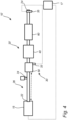
- a vehicle 1, here embodied as a heavy duty truck 1, is shown for which an engine system 10 of a kind disclosed in the present disclosure is advantageous.
- the engine system 10 of the vehicle 1 of Fig. 1 comprises a hydrogen combustion engine 15 and an exhaust aftertreatment system, EATS, 20 configured to reduce emission of the engine exhausts.
- the vehicle may according to at least one example embodiment be a hybrid vehicle further comprising an electric machine 16 (optionally).
- the hydrogen combustion engine 15 is powered by hydrogen fuel, typically comprised in a fuel tank, and any electric machine 16 is typically powered by electricity supplied from at least one energy storage or transformation device, e.g. a battery or a fuel cell (not shown).
- the hydrogen combustion engine 15 is preferably configured to be operated by an Otto cycle.
- the operation of the engine system 10 may e.g. be controlled by a controlling apparatus 17.
- the EATS 20 comprises a plurality of emission reducing modules 30 arranged downstream of an exhaust gas inlet (shown in Fig. 2 ) of the EATS 20.
- the emission reducing modules 30 are configured to reduce emissions of the engine exhausts.
- the plurality of emission reducing modules 30 comprises at least a first emission reducing module 40 and a second reducing module 50.
- the first reducing module 40 is arranged upstream of the second reducing module 50, but as an alternative, the second emission reducing module 50 may be arranged upstream of the first reducing module 40.
- the numbering of the plurality of emission reducing modules 30 does not refer to the order at which they are arranged, the numbering (i.e.
- the first and second emission reducing modules 40, 50 are configured to remove particles, e.g. particulate matter or soot, from the exhaust gases (also referred to as engine exhausts) of the hydrogen combustion engine 15 and to convert nitrogen oxides, also referred to as NOx, with the aid of a catalyst, into diatomic nitrogen, N2, and water and/or carbon dioxide CO2, as will be described with reference to Figs. 2 and 3 .
- the EATS 20 typically comprise further components such as e.g. piping and additional emission reducing components (not shown in Fig. 1 ).
- the engine system 10 of Fig. 1 is shown in greater detail.
- the engine system 10 comprises the hydrogen combustion engine 15 and the exhaust aftertreatment system, EATS, 20 configured to reduce emissions of the engine exhausts, described briefly with reference to Fig. 1 .
- the engine exhaust is in the following referred to as exhaust gases.
- the EATS 20 comprises an exhaust gas inlet 22 for receiving engine exhaust from the hydrogen combustion engine 15, an outlet 24 for discharging at least partly cleaned exhaust gases from the EATS 20, and a fluid pathway 26 for transporting the exhaust gases from the inlet 22 to the outlet 24.
- the outlet 24 may e.g. be connected to, or comprise, the tailpipe of the vehicle 1.
- the EATS 20 further comprises a plurality of emission reducing modules 30 arranged downstream of the exhaust gas inlet 22.
- the emission reducing modules 30 are configured to reduce emissions of the engine exhausts along the fluid pathway 26.
- the plurality of emission reducing modules 30 is composed of a first emission reducing module 40, a second emission reducing module 50 and a third emission reducing module 60 which will be described in more detail in the following.
- the first emission reducing module 40 comprises a porous substrate 42 having an inlet face 44 and an outlet face 46.
- the porous substrate 42 comprises inlet channels 45 extending from the inlet face 44 and towards, but no to, the outlet face 46. Thus, the inlet channels 45 are closed, or blinded.
- the porous substrate 42 further comprises outlet channels 47 extending from the outlet face 46 and towards, but not to, the inlet face 44. Thus, the outlet channels 47 are closed, or blinded.
- the inlet channels 45 extend from a respective open end at the inlet face 44 to a respective closed end arranged closer to the outlet face 46 (but within the porous substrate 42), and the outlet channels 47 extend from a respective open end at the outlet face 46 to a respective closed end arranged closer to the inlet face 44 (but within the porous substrate 42).
- the inlet channels 45 and the outlet channels 47 are separated by a plurality of filter walls 42a, 42b, 42c having a porous structure.
- the exhaust gases are forced through the filter walls 42a, 42b, 42c during use of the porous substrate 42.
- the porous substrate 42 may have been loaded with a powder coating comprising aerosols of alumina or silica.
- the porous substrate 42 may have been loaded with the powder coating by a loading of ⁇ 10 g/L of dry powder, or ⁇ 5 g/L of dry powder, or ⁇ 2 g/L of dry powder.
- the porous substrate 42 may have been loaded with the powder coating by a loading relative to a filter volume of the porous substrate of between 0.5 g/L and 10 g/L, or of between 0.5 g/L and 5 g/L, or of between 0.5 g/L and 2 g/L.
- the resulting powder coating concentration relative to the filter volume of the porous substrate may be ranging from 0.01 g/L to 60 g/L.
- the second emission reducing module 50 is a selective catalyst reduction, SCR, catalyst unit 50.
- the SCR catalyst unit 50 is an SCR catalyst stone 50.
- the SCR catalyst unit 50 may be of a zeolite type, e.g. Cu-zeolite.
- the SCR catalyst unit is different to the SCR catalyst coating(s) 49a, 49b of the first emission reducing module 40.
- the EATS 20 comprises an injector 34 configured to inject a reductant to the fluid pathway 26 upstream of at least the first occurring emission reducing module of the EATS 20, and downstream of the exhaust gas inlet 22.
- the reductant may e.g. be urea.
- the injector 34 may be configured to inject urea.
- the first emission reducing module 40 (comprising the porous filter 42 shown in Fig. 3 ) is arranged as the first occurring emission reducing module of the EATS 20 downstream of the exhaust gas inlet 22.
- the exhaust gases of the EATS 20 first encounter the porous structure 42 and the powder coating 48, wherein particulate emissions, such as e.g. sulphur containing emissions, is filtered from the exhaust gases, thereby reducing the deterioration of the downstream arranged SCR catalyst (as the SCR catalyst coatings 49a, 49b, and the SCR catalyst unit 50).
- the porous filter 42 may be easily accessible in the EATS 20, and may thus be made accessible for maintenance or exchange.
- the porous filter 42 may be accessed via the exhaust gas inlet 22.
- the positioning of the injector 34 may be more freely chosen as there is no other emission reducing module between the exhaust gas inlet 22 and the first emission reducing module 40.
- the injector may be arranged anywhere between the exhaust gas inlet 22 and the first emission reducing module 40, indicated by the dashed arrow in Fig. 2 .
- the EATS 20' comprises the same components, and in particular the same plurality of emission reducing modules 30 as in the EATS 20 of Fig. 2 , why the same reference numerals are used in Fig. 4 .
- the second emission reducing module 50 being the SCR catalyst unit 50 is arranged as the first occurring emission reducing module of the EATS 20' downstream of the exhaust gas inlet 22.
- the exhaust gases first encounter the SCR catalyst unit 50 and NOx emissions may be efficiently reduced.
- the SCR catalyst unit 50 may be easily accessible in the EATS 20', and may thus be made accessible for maintenance or exchange.
- the SCR catalyst unit 50 may be accessed via the exhaust gas inlet 22.
- the positioning of the injector 34 may be freely chosen, here between the exhaust gas inlet 22 and the second emission reducing module 50 (indicated by the dashed arrow in Fig. 4 ).
- the third emission reducing module 60 of the EATS 20, 20' of Figs. 2 and 4 is optional.
- the third emission reducing module 60 is one of: an oxidation catalyst, an ammonia slip catalyst, a secondary particulate filter.
- the third emission reducing module 60 is an ammonia slip catalyst, any ammonia slip from the corresponding SCR catalyst (of the first and/or second emission reducing modules 40, 50) may be handled.
- the third emission reducing module 60 is arranged downstream of both of the first and second emission reducing modules 40, 50.
- the third emission reducing module 60 is arranged in between the first and second emission reducing modules 40, 50.
- the third emission reducing module 60 may be an oxidation catalyst or a secondary particulate filter.
- the third emission reducing module 60 is still arranged downstream of the first emission reducing module 40 and/or the second emission reducing module 50, whichever being arranged as the first occurring emission reducing module of the EATS 20, 20' downstream of the exhaust gas inlet 22.
- the third emission reducing module 60 is optional and may be omitted.
- the engine system 10 of Fig. 2 , and engine system 10' of Fig. 4 are typically operated in the following manner: engine exhausts, or exhaust gases (to be cleaned) from the hydrogen combustion engine 15, enter the EATS 20, 20' via the exhaust gas inlet 22, and encounters the first occurring emission reducing module downstream of the exhaust gas inlet 22, the first occurring emission reducing module being either the first emission reducing module 40 or the second emission reducing module 50. Thereafter, the exhaust gases passes through the other one of the first and second emission reducing module 40, 50 (which is not being the first occurring emission reducing module). Typically, upstream of the first occurring emission reducing module downstream of the exhaust gas inlet, reductant is injected via the injector 34. The injected reductant is thus mixed with the exhaust gases.
- the reductant is evaporated and hydrolysed into ammonia.
- the ammonia and exhaust gases thereafter encounters the SCR catalyst coating 49a, 49b and/or the SCR catalyst unit 50 for achieving catalytic reduction of the NOx, whereafter the cleaned exhaust gases are discharged from the EATS 20, 20' via the outlet 24, possibly subsequent to passing the third emission reducing module 60.
- particles e.g. particulate matter or soot, is removed from the exhaust gases owing to the powder coating 48, and NOx is converted, with the aid of a catalyst, into diatomic nitrogen, N2, and water, owing to the SCR catalyst coatings 49a, 49b and the SCR catalyst unit 50.
- the EATS 20, 20' may comprise means for providing determination/measurement of various parameters, such as e.g. the temperature of the SCR catalyst unit 50 by means of a temperature sensor 33, and/or the NOx at the outlet 24 of the EATS 20, 20' by means of a NOx sensor 35.
- the operation of the engine system 10, 10' may as previously described be controlled by controlling apparatus 17.
- first, second and third emission reducing modules 40, 50, 60 are structurally and (at least partly) functionally separated from each other.
- each one of the first, second and third emission reducing module 40, 50, 60 may be housed in a separate container or canister.
- the EATS may be used for cleaning exhaust gases in a dual-fuel engine system (in which one of the engines is a hydrogen combustion engine).
- the present EATS may be used to clean exhaust gases, e.g. by converting NOx emissions, from the exhaust of internal combustion engines based on H2 (Hydrogen) or a mix of H2 and natural gas.
Landscapes
- Engineering & Computer Science (AREA)
- Chemical & Material Sciences (AREA)
- Chemical Kinetics & Catalysis (AREA)
- Combustion & Propulsion (AREA)
- Mechanical Engineering (AREA)
- General Engineering & Computer Science (AREA)
- Health & Medical Sciences (AREA)
- Materials Engineering (AREA)
- Toxicology (AREA)
- Biomedical Technology (AREA)
- Environmental & Geological Engineering (AREA)
- Analytical Chemistry (AREA)
- General Chemical & Material Sciences (AREA)
- Oil, Petroleum & Natural Gas (AREA)
- Organic Chemistry (AREA)
- Ceramic Engineering (AREA)
- Exhaust Gas After Treatment (AREA)
Claims (13)
- Motorsystem (10, 10'), welches einen Wasserstoffverbrennungsmotor (15) und ein Abgasnachbehandlungssystem, EATS (20, 20'), umfasst, das konfiguriert ist, um die Emissionen der Motorabgase zu reduzieren, wobei das EATS (20, 20') Folgendes umfasst:- einen Abgaseinlass (22) zur Aufnahme von Motorabgas aus dem Wasserstoffverbrennungsmotor (15) ;- mehrere Emissionsreduktionsmodule (30), die nach dem Abgaseinlass (22) angeordnet und so konfiguriert sind, um die Emissionen der Motorabgase zu verringern, wobei die mehreren Emissionsreduktionsmodule (30) mindestens Folgendes umfassen:wobei eines der ersten und zweiten Emissionsreduktionsmodule (40, 50) als das erste auftretende Emissionsreduktionsmodul des EATS (20, 20') nach dem Abgaseinlass (22) angeordnet ist, dadurch gekennzeichnet, dass die Einlasskanäle (45) des porösen Substrats (42) mit einer Pulverbeschichtung (48) beladen sind, die konfiguriert ist, um Partikel aus dem Motorabgas zu filtern.- ein erstes Emissionsreduktionsmodul (40) mit einem porösen Substrat (42) mit einer Einlassfläche (44) und einer Auslassfläche (46), wobei das poröse Substrat (42) Einlasskanäle (45), die sich von der Einlassfläche (44) erstrecken, und Auslasskanäle (47), die sich von der Auslassfläche (46) erstrecken, umfasst; wobei die Einlasskanäle (45) und die Auslasskanäle (47) durch mehrere Filterwände (42a, 42b, 42c) mit einer porösen Struktur getrennt sind; wobei die poröse Struktur der Filterwände (42a, 42b, 42c) und/oder der Auslasskanäle (47) des porösen Substrats (42) mit einer Katalysatorbeschichtung (49a, 49b) mit selektiv-katalytischer Reduktion, SCR, beladen ist;- ein zweites Emissionsreduktionsmodul (50), bei dem es sich um eine Katalysatoreinheit mit selektiv-katalytischer Reduktion, SCR, handelt;
- Motorsystem (10) nach Anspruch 1, wobei das erste Emissionsreduktionsmodul (40) als das erste auftretende Emissionsreduktionsmodul des EATS (20) nach dem Abgaseinlass (22) angeordnet ist.
- Motorsystem (10') nach Anspruch 1, wobei das zweite Emissionsreduktionsmodul (50) wie das erste auftretende Emissionsreduktionsmodul des EATS (20') nach dem Abgaseinlass (22) angeordnet ist.
- Motorsystem (10, 10') nach einem der vorhergehenden Ansprüche, wobei die mehreren Emissionsreduktionsmodule (30) ferner ein drittes Emissionsreduktionsmodul (60) umfasst, das ausgewählt ist aus: einem Oxidationskatalysator, einem Ammoniakschlupfkatalysator, einem sekundären Partikelfilter, und wobei das dritte Emissionsreduktionsmodul (60) nach dem ersten oder zweiten Emissionsreduktionsmodul (40, 50) angeordnet ist, je nachdem, welches als das zuerst auftretende Emissionsreduktionsmodul des EATS (20, 20') nach dem Abgaseinlass (22) angeordnet ist, oder nach sowohl dem ersten als auch dem zweiten Emissionsreduktionsmodul (40, 50) angeordnet ist.
- Motorsystem (10, 10') nach einem der vorhergehenden Ansprüche, wobei das EATS ferner umfasst:- eine Einspritzdüse (34), die konfiguriert ist, um ein Reduktionsmittel einzuspritzen, um der SCR-Katalysatorbeschichtung (49a, 49b) und/oder der SCR-Katalysatoreinheit (50) Ammoniak zuzuführen, wobei die Einspritzdüse (34) vor dem ersten und zweiten Emissionsreduktionsmodul (40, 50) und nach dem Abgaseinlass (22) angeordnet ist.
- Motorsystem (10, 10') nach einem der vorhergehenden Ansprüche, wobei die SCR-Katalysatorbeschichtung (49a, 49b) des ersten Emissionsreduktionsmoduls (40) eine Vanadia-basierte Beschichtung ist.
- Motorsystem (10, 10') nach einem der vorhergehenden Ansprüche, wobei das poröse Substrat (42) mit einem Trockenpulver beladen wurde, das ein Metalloxid umfasst.
- Motorsystem (10, 10') nach einem der vorhergehenden Ansprüche, wobei das poröse Substrat (42) mit der Pulverbeschichtung (48) durch eine Beladung von <10 g/l Trockenpulver, vorzugsweise <5 g/l Trockenpulver, vorzugsweise <2 g/l Trockenpulver, beladen wurde.
- Motorsystem (10, 10') nach einem der vorhergehenden Ansprüche, wobei die Pulverbeschichtungskonzentration bezogen auf ein Filtervolumen des porösen Substrats (42) im Bereich von 0,01 g/L bis 60 g/L liegt.
- Motorsystem (10, 10') nach einem der vorhergehenden Ansprüche, wobei die SCR-Katalysator-Beschichtungskonzentration relativ zu einem Filtervolumen des porösen Substrats (42) im Bereich von 10 g/L bis 150 g/L liegt.
- Motorsystem (10, 10') nach einem der vorhergehenden Ansprüche, wobei das EATS frei von jeglichem Oxidationskatalysator ist, der nach dem Abgaseinlass (22) und vor dem ersten und zweiten Emissionsreduktionsmodul (40, 50) angeordnet ist.
- Motorsystem (10, 10') nach einem der vorhergehenden Ansprüche, wobei der Wasserstoffverbrennungsmotor (15) konfiguriert ist, um nach einem Otto-Zyklus betrieben zu werden.
- Fahrzeug (1) umfassend ein Motorsystem (10, 10) nach einem der Ansprüche 1-12.
Priority Applications (3)
| Application Number | Priority Date | Filing Date | Title |
|---|---|---|---|
| EP22179031.4A EP4293207B1 (de) | 2022-06-14 | 2022-06-14 | Motorsystem, welches einen wasserstoffverbrennungsmotor und ein abgasreinigungssystem umfasst |
| CN202310681138.1A CN117231355A (zh) | 2022-06-14 | 2023-06-09 | 包括氢燃烧发动机的发动机系统 |
| US18/333,164 US20230399972A1 (en) | 2022-06-14 | 2023-06-12 | Engine system comprising a hydrogen combustion engine |
Applications Claiming Priority (1)
| Application Number | Priority Date | Filing Date | Title |
|---|---|---|---|
| EP22179031.4A EP4293207B1 (de) | 2022-06-14 | 2022-06-14 | Motorsystem, welches einen wasserstoffverbrennungsmotor und ein abgasreinigungssystem umfasst |
Publications (3)
| Publication Number | Publication Date |
|---|---|
| EP4293207A1 EP4293207A1 (de) | 2023-12-20 |
| EP4293207B1 true EP4293207B1 (de) | 2025-02-26 |
| EP4293207C0 EP4293207C0 (de) | 2025-02-26 |
Family
ID=82058487
Family Applications (1)
| Application Number | Title | Priority Date | Filing Date |
|---|---|---|---|
| EP22179031.4A Active EP4293207B1 (de) | 2022-06-14 | 2022-06-14 | Motorsystem, welches einen wasserstoffverbrennungsmotor und ein abgasreinigungssystem umfasst |
Country Status (3)
| Country | Link |
|---|---|
| US (1) | US20230399972A1 (de) |
| EP (1) | EP4293207B1 (de) |
| CN (1) | CN117231355A (de) |
Family Cites Families (4)
| Publication number | Priority date | Publication date | Assignee | Title |
|---|---|---|---|---|
| US20130047583A1 (en) * | 2011-08-31 | 2013-02-28 | Caterpillar Inc. | Aftertreatment system |
| AT524011B1 (de) * | 2020-07-03 | 2022-04-15 | Avl List Gmbh | Kraftfahrzeug mit einem mit kohlenstofffreiem Kraftstoff betriebenen Verbrennungsmotor mit daran angeschlossenem Abgassystem |
| DE102020209154A1 (de) * | 2020-07-21 | 2022-01-27 | Vitesco Technologies GmbH | Abgasstrang für einen Wasserstoffverbrennungsmotor und Verfahren zum Betreiben eines Abgasstrangs eines Wasserstoffverbrennungsmotors |
| DE102020006451A1 (de) * | 2020-10-20 | 2021-03-18 | FEV Group GmbH | Steuergerät zum Steuern eines Wasserstoffgehalts eines Abgases eines Verbrennungsmotors |
-
2022
- 2022-06-14 EP EP22179031.4A patent/EP4293207B1/de active Active
-
2023
- 2023-06-09 CN CN202310681138.1A patent/CN117231355A/zh active Pending
- 2023-06-12 US US18/333,164 patent/US20230399972A1/en active Pending
Also Published As
| Publication number | Publication date |
|---|---|
| EP4293207C0 (de) | 2025-02-26 |
| CN117231355A (zh) | 2023-12-15 |
| US20230399972A1 (en) | 2023-12-14 |
| EP4293207A1 (de) | 2023-12-20 |
Similar Documents
| Publication | Publication Date | Title |
|---|---|---|
| US20250032984A1 (en) | Close-coupled scr system | |
| Johnson | Diesel emission control in review | |
| US8887495B2 (en) | Ash filter, exhaust gas treatment system incorporating the same and method of using the same | |
| US8312708B2 (en) | Closely coupled exhaust aftertreatment system for a turbocharged engine | |
| US8276366B2 (en) | Closely coupled exhaust aftertreatment system for an internal combustion engine having twin turbochargers | |
| US20180291827A1 (en) | Exhaust gas treatment system warm-up methods | |
| US20120247088A1 (en) | Exhaust gas after-treatment system | |
| Zhang et al. | Effect of SCR downsizing and ammonia slip catalyst coating on the emissions from a heavy-duty diesel engine | |
| US20100326059A1 (en) | Selective catalytic reduction exhaust aftertreatment system and engine incorporating the same | |
| WO2011045847A1 (ja) | エンジンの排気浄化装置 | |
| WO2015040047A2 (en) | Exhaust treatment apparatus and method | |
| EP4551799B1 (de) | Steuerungsverfahren für das betreiben eines wasserstoffverbrennungsmotors | |
| Maunula | Intensification of catalytic aftertreatments systems for mobile applications | |
| EP4293207B1 (de) | Motorsystem, welches einen wasserstoffverbrennungsmotor und ein abgasreinigungssystem umfasst | |
| JP6020105B2 (ja) | ディーゼルエンジンの排気ガス浄化方法及び排気ガス浄化システム | |
| YASHNIK et al. | Problems of the soot formation in exhausts of internal combustion engines. Soot abatement by oxidation on Cu-Containing ZSM-5 catalysts (Minireview) | |
| US12529347B2 (en) | Method for controlling the operation of a hydrogen combustion engine system of a vehicle | |
| Brück et al. | NOx aftertreatment for passenger cars and heavy duty truck applications for EU 6 and EUVI/US2010 legislation | |
| Hare et al. | Use of catalytic converter for achieving efficient and economic emission reduction | |
| CN217152079U (zh) | 一种排气系统 | |
| US12421881B2 (en) | System and method for reducing internal combustion engine emissions | |
| Garg | Exhaust Hybrid After Treatment System in Vehicles Using IT Applications | |
| Schaml et al. | Highly integrated exhaust gas aftertreatment systems in heavy-duty applications | |
| CN117345379A (zh) | 一种氨在线制氢存储用于dpf再生的系统和方法 | |
| de Mattos Lourenço et al. | OPTIMIZATION OF SELECTIVE-TYPE AFTERTREATMENT SYSTEMS IN DIESEL ENGINES |
Legal Events
| Date | Code | Title | Description |
|---|---|---|---|
| PUAI | Public reference made under article 153(3) epc to a published international application that has entered the european phase |
Free format text: ORIGINAL CODE: 0009012 |
|
| STAA | Information on the status of an ep patent application or granted ep patent |
Free format text: STATUS: THE APPLICATION HAS BEEN PUBLISHED |
|
| AK | Designated contracting states |
Kind code of ref document: A1 Designated state(s): AL AT BE BG CH CY CZ DE DK EE ES FI FR GB GR HR HU IE IS IT LI LT LU LV MC MK MT NL NO PL PT RO RS SE SI SK SM TR |
|
| STAA | Information on the status of an ep patent application or granted ep patent |
Free format text: STATUS: REQUEST FOR EXAMINATION WAS MADE |
|
| 17P | Request for examination filed |
Effective date: 20240612 |
|
| RBV | Designated contracting states (corrected) |
Designated state(s): AL AT BE BG CH CY CZ DE DK EE ES FI FR GB GR HR HU IE IS IT LI LT LU LV MC MK MT NL NO PL PT RO RS SE SI SK SM TR |
|
| GRAP | Despatch of communication of intention to grant a patent |
Free format text: ORIGINAL CODE: EPIDOSNIGR1 |
|
| STAA | Information on the status of an ep patent application or granted ep patent |
Free format text: STATUS: GRANT OF PATENT IS INTENDED |
|
| INTG | Intention to grant announced |
Effective date: 20240920 |
|
| GRAS | Grant fee paid |
Free format text: ORIGINAL CODE: EPIDOSNIGR3 |
|
| GRAA | (expected) grant |
Free format text: ORIGINAL CODE: 0009210 |
|
| STAA | Information on the status of an ep patent application or granted ep patent |
Free format text: STATUS: THE PATENT HAS BEEN GRANTED |
|
| AK | Designated contracting states |
Kind code of ref document: B1 Designated state(s): AL AT BE BG CH CY CZ DE DK EE ES FI FR GB GR HR HU IE IS IT LI LT LU LV MC MK MT NL NO PL PT RO RS SE SI SK SM TR |
|
| REG | Reference to a national code |
Ref country code: GB Ref legal event code: FG4D |
|
| REG | Reference to a national code |
Ref country code: CH Ref legal event code: EP |
|
| REG | Reference to a national code |
Ref country code: DE Ref legal event code: R096 Ref document number: 602022011010 Country of ref document: DE |
|
| REG | Reference to a national code |
Ref country code: IE Ref legal event code: FG4D |
|
| U01 | Request for unitary effect filed |
Effective date: 20250321 |
|
| U07 | Unitary effect registered |
Designated state(s): AT BE BG DE DK EE FI FR IT LT LU LV MT NL PT RO SE SI Effective date: 20250327 |
|
| PG25 | Lapsed in a contracting state [announced via postgrant information from national office to epo] |
Ref country code: RS Free format text: LAPSE BECAUSE OF FAILURE TO SUBMIT A TRANSLATION OF THE DESCRIPTION OR TO PAY THE FEE WITHIN THE PRESCRIBED TIME-LIMIT Effective date: 20250526 |
|
| PG25 | Lapsed in a contracting state [announced via postgrant information from national office to epo] |
Ref country code: PL Free format text: LAPSE BECAUSE OF FAILURE TO SUBMIT A TRANSLATION OF THE DESCRIPTION OR TO PAY THE FEE WITHIN THE PRESCRIBED TIME-LIMIT Effective date: 20250226 |
|
| PG25 | Lapsed in a contracting state [announced via postgrant information from national office to epo] |
Ref country code: ES Free format text: LAPSE BECAUSE OF FAILURE TO SUBMIT A TRANSLATION OF THE DESCRIPTION OR TO PAY THE FEE WITHIN THE PRESCRIBED TIME-LIMIT Effective date: 20250226 |
|
| PG25 | Lapsed in a contracting state [announced via postgrant information from national office to epo] |
Ref country code: IS Free format text: LAPSE BECAUSE OF FAILURE TO SUBMIT A TRANSLATION OF THE DESCRIPTION OR TO PAY THE FEE WITHIN THE PRESCRIBED TIME-LIMIT Effective date: 20250626 Ref country code: NO Free format text: LAPSE BECAUSE OF FAILURE TO SUBMIT A TRANSLATION OF THE DESCRIPTION OR TO PAY THE FEE WITHIN THE PRESCRIBED TIME-LIMIT Effective date: 20250526 |
|
| PG25 | Lapsed in a contracting state [announced via postgrant information from national office to epo] |
Ref country code: HR Free format text: LAPSE BECAUSE OF FAILURE TO SUBMIT A TRANSLATION OF THE DESCRIPTION OR TO PAY THE FEE WITHIN THE PRESCRIBED TIME-LIMIT Effective date: 20250226 |
|
| PG25 | Lapsed in a contracting state [announced via postgrant information from national office to epo] |
Ref country code: GR Free format text: LAPSE BECAUSE OF FAILURE TO SUBMIT A TRANSLATION OF THE DESCRIPTION OR TO PAY THE FEE WITHIN THE PRESCRIBED TIME-LIMIT Effective date: 20250527 |
|
| U20 | Renewal fee for the european patent with unitary effect paid |
Year of fee payment: 4 Effective date: 20250624 |
|
| PG25 | Lapsed in a contracting state [announced via postgrant information from national office to epo] |
Ref country code: SM Free format text: LAPSE BECAUSE OF FAILURE TO SUBMIT A TRANSLATION OF THE DESCRIPTION OR TO PAY THE FEE WITHIN THE PRESCRIBED TIME-LIMIT Effective date: 20250226 |
|
| PG25 | Lapsed in a contracting state [announced via postgrant information from national office to epo] |
Ref country code: CZ Free format text: LAPSE BECAUSE OF FAILURE TO SUBMIT A TRANSLATION OF THE DESCRIPTION OR TO PAY THE FEE WITHIN THE PRESCRIBED TIME-LIMIT Effective date: 20250226 |
|
| PG25 | Lapsed in a contracting state [announced via postgrant information from national office to epo] |
Ref country code: SK Free format text: LAPSE BECAUSE OF FAILURE TO SUBMIT A TRANSLATION OF THE DESCRIPTION OR TO PAY THE FEE WITHIN THE PRESCRIBED TIME-LIMIT Effective date: 20250226 |
|
| PLBE | No opposition filed within time limit |
Free format text: ORIGINAL CODE: 0009261 |
|
| STAA | Information on the status of an ep patent application or granted ep patent |
Free format text: STATUS: NO OPPOSITION FILED WITHIN TIME LIMIT |
|
| REG | Reference to a national code |
Ref country code: CH Ref legal event code: L10 Free format text: ST27 STATUS EVENT CODE: U-0-0-L10-L00 (AS PROVIDED BY THE NATIONAL OFFICE) Effective date: 20260107 |
|
| REG | Reference to a national code |
Ref country code: CH Ref legal event code: H13 Free format text: ST27 STATUS EVENT CODE: U-0-0-H10-H13 (AS PROVIDED BY THE NATIONAL OFFICE) Effective date: 20260127 |
|
| PG25 | Lapsed in a contracting state [announced via postgrant information from national office to epo] |
Ref country code: MC Free format text: LAPSE BECAUSE OF FAILURE TO SUBMIT A TRANSLATION OF THE DESCRIPTION OR TO PAY THE FEE WITHIN THE PRESCRIBED TIME-LIMIT Effective date: 20250226 |
|
| 26N | No opposition filed |
Effective date: 20251127 |