EP3872025B1 - Kranvorrichtung, verfahren zur bestimmung der anzahl von fällen und programm - Google Patents
Kranvorrichtung, verfahren zur bestimmung der anzahl von fällen und programm Download PDFInfo
- Publication number
- EP3872025B1 EP3872025B1 EP19875505.0A EP19875505A EP3872025B1 EP 3872025 B1 EP3872025 B1 EP 3872025B1 EP 19875505 A EP19875505 A EP 19875505A EP 3872025 B1 EP3872025 B1 EP 3872025B1
- Authority
- EP
- European Patent Office
- Prior art keywords
- rope
- boom
- length
- falls
- crane device
- Prior art date
- Legal status (The legal status is an assumption and is not a legal conclusion. Google has not performed a legal analysis and makes no representation as to the accuracy of the status listed.)
- Active
Links
Images

Classifications
-
- B—PERFORMING OPERATIONS; TRANSPORTING
- B66—HOISTING; LIFTING; HAULING
- B66C—CRANES; LOAD-ENGAGING ELEMENTS OR DEVICES FOR CRANES, CAPSTANS, WINCHES, OR TACKLES
- B66C13/00—Other constructional features or details
- B66C13/18—Control systems or devices
- B66C13/46—Position indicators for suspended loads or for crane elements
-
- B—PERFORMING OPERATIONS; TRANSPORTING
- B66—HOISTING; LIFTING; HAULING
- B66C—CRANES; LOAD-ENGAGING ELEMENTS OR DEVICES FOR CRANES, CAPSTANS, WINCHES, OR TACKLES
- B66C13/00—Other constructional features or details
-
- B—PERFORMING OPERATIONS; TRANSPORTING
- B66—HOISTING; LIFTING; HAULING
- B66C—CRANES; LOAD-ENGAGING ELEMENTS OR DEVICES FOR CRANES, CAPSTANS, WINCHES, OR TACKLES
- B66C23/00—Cranes comprising essentially a beam, boom, or triangular structure acting as a cantilever and mounted for translatory of swinging movements in vertical or horizontal planes or a combination of such movements, e.g. jib-cranes, derricks, tower cranes
- B66C23/88—Safety gear
- B66C23/90—Devices for indicating or limiting lifting moment
- B66C23/905—Devices for indicating or limiting lifting moment electrical
-
- B—PERFORMING OPERATIONS; TRANSPORTING
- B66—HOISTING; LIFTING; HAULING
- B66D—CAPSTANS; WINCHES; TACKLES, e.g. PULLEY BLOCKS; HOISTS
- B66D3/00—Portable or mobile lifting or hauling appliances
- B66D3/04—Pulley blocks or like devices in which force is applied to a rope, cable, or chain which passes over one or more pulleys, e.g. to obtain mechanical advantage
- B66D3/043—Block and tackle system with variable number of cable parts
Definitions
- the invention provides a crane device in accordance with independent claim 1.
- the invention provides a method for determining a number of falls for a rope in a crane device in accordance with independent claim 6.
- the invention provides a program in accordance with independent claim 7. Further aspects of the invention are set forth in the dependent claims, the drawings, and the following description.
- a method for determining the number of falls according to the present invention is a method for determining the number of falls for the rope in a crane device, capable of setting multiple types of number of falls of the rope between a tip of a boom and a hook block, and includes: a step of acquiring a feed length of the rope fed from a winch on which the rope is wound; a step of acquiring a hoist angle of the boom; a step of acquiring a boom length of the boom; and a step of calculating information for determining suitability of the number of falls for the rope on the basis of the feed length, the hoist angle, the boom length in a state of hoisting a grounded load.
- the present invention it is possible to determine whether the actual number of falls of the rope and the number of falls for the rope stored in a number-of-falls storage unit are the same by a device provided in the conventional crane device without increasing the number of parts, and thus, it is possible to suppress an increase in manufacturing cost.
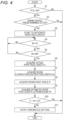
- Figs. 1 to 5 illustrate one embodiment of the present invention.
- the present invention is applied to a crane device 20 of a mobile crane 1.
- the vehicle body 10 includes wheels 11 provided on both sides in the width direction on the front side and the rear side, and outriggers 12 provided in front of the front-side wheels 11 and behind the rear-side wheels 11.
- the vehicle body 10 travels by a driving force of an engine.
- the crane device 20 includes: a telescoping boom 21 configured to be raisable and elongatable/contractible with respect to the vehicle body 10; a rope 22 that extends along the telescoping boom 21 and hangs from a tip of the telescoping boom 21; a winch 23 winding and feeding the rope 22; and a hook block 24 that is locked to the rope 22 hanging from the tip of the telescoping boom 21.
- the telescoping boom 21 is constituted by a plurality of boom members formed in a tubular shape, and has a telescopic elongation/contraction mechanism.
- the telescoping boom 21 performs an elongation/contraction operation by a hydraulic elongation/contraction cylinder (not illustrated).
- the telescoping boom 21 has a proximal end connected to the turning base 40 to be swingable in the vertical direction.
- a hydraulic raising cylinder 21a is connected between a substantially central portion of the telescoping boom 21 in the extending direction and the turning base 40, and the telescoping boom 21 performs a raising operation by an elongation/contraction operation of the raising cylinder 21a.
- the rope 22 is a wire rope obtained by twisting a plurality of strands formed by twisting hard steel wires, or a synthetic fiber rope made of synthetic fibers.
- the winch 23 is provided at a position adjacent to the proximal end of the telescoping boom 21 on the turning base 40.
- the winch 23 includes a winch drum 23a on which a rope 22 is wound, and a hydraulic winch motor (not illustrated) configured to rotate the winch drum 23a.
- a winding operation and a feeding operation of the rope 22 in the winch drum 23a can be switched by switching a driving direction of a rotation shaft of the winch motor.
- the turning base 40 is rotatably provided with respect to the vehicle body 10 via a ball bearing type or roller bearing type turning circle, and turns by a hydraulic turning motor (not illustrated).
- actuators such as the telescopic cylinder, the raising cylinder 21a, the winch motor, and the swivel motor configured to drive the crane device 20 are driven by hydraulic oil discharged from a hydraulic pump (not illustrated) driven by motive power of the engine.
- the driving force of the engine is transmitted to the hydraulic pump via the power take-off (PTO) mechanism.
- PTO power take-off
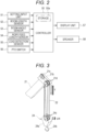
- the controller 50 has a CPU, a ROM, a RAM, and the like.
- the CPU when receiving an input signal from a device connected to the input side, the CPU reads a program stored in the ROM based on the input signal, and stores a state detected by the input signal in the RAM or transmits an output signal to the device connected to the output side.
- a setting input unit 51 is an input device configured for an operator to input settings during the operation of the crane device 20.
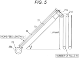
- the boom length sensor 52 is a boom length detection unit configured to detect an elongation/contraction length Lb of the telescoping boom 21.
- the boom angle sensor 53 is a boom angle detection unit configured to detect a hoist angle ⁇ of the telescoping boom 21.
- the rope feed length sensor 54 is a feed length detection unit configured to detect a feed length Lr of the rope 22 fed from the winch drum 23a.
- the load detection sensor 55 is a load detection unit configured to detect a load W, such as baggage, acting on the hook block 24 and the tip of the telescoping boom 21.
- the PTO switch 56 switches a PTO mechanism between a state where the driving force of the engine is transmitted to the hydraulic pump (on) and a state where the transmission is cut off (off).
- a display unit 57 and a speaker 58 are connected to the output side of the controller 50.
- the display unit 57 and the speaker 58 function as a notification unit configured to notify the operator in the cab 30 of a state of the crane device 20 including the suitability of the number of falls of the rope 22.
- the setting input unit 51 is a touch panel having the function of the display unit 57 and the functions as an input device, such as a liquid crystal panel.
- the setting input unit 51 is operated by the operator when setting a set number of falls R for the rope 22 wound between the boom head 21b of the telescoping boom 21 and the hook block 24. Information on the set number of falls R set by the setting input unit 51 is stored in a storage unit 50a of the controller 50.
- the boom length sensor 52 is provided, for example, on the proximal side of the telescoping boom 21, and includes: a cord reel in which a tip of a cord to be fed is connected to a boom member on the most distal side; and a rotary encoder connected to a rotation shaft of the cord reel.
- the boom length sensor 52 acquires the boom length Lb of the telescoping boom 21 based on a detection result of a rotation speed of the rotary encoder.
- the boom angle sensor 53 has, for example, a potentiometer attached to a side surface of a boom member on the most proximal side of the telescoping boom 21.
- the boom angle sensor 53 acquires the hoist angle ⁇ of the telescoping boom 21 based on a detection result of the potentiometer.
- the rope feed length sensor 54 has, for example, a rotary encoder configured to detect a rotation speed of the winch drum 23a of the winch 23.
- the rope feed length sensor 54 acquires the feed length Lr of the rope 22 fed from the winch 23 based on a detection result of the rotation speed of the rotary encoder.
- the load detection sensor 55 has, for example, a pressure sensor configured to detect the pressure in the raising cylinder 21a.
- the load detection sensor 55 acquires a load acting on the tip of the telescoping boom 21 based on the detected pressure of the pressure sensor.
- each of the moving speed of the hook block 24 with respect to the winding/feeding speed of the rope 22, the moving amount of the hook block 24 with respect to the winding/feeding amount of the rope 22, and the tensile force of the rope 22 required to lift the hook block 24 and the baggage is one-third of that in the case where the number of falls is one.
- the predetermined state is, for example, a state where an operation of the crane device 20 other than the raising operation of the telescoping boom 21 or the operation of the winch 23 has been input after an attitude of the hook block 24 is changed from a retracted attitude to a working attitude in the so-called hook-in type crane device 20 in which the hook block 24 is in the retracted attitude at the tip of the telescoping boom 21.
- the predetermined state is a state where an operation of the crane device 20 other than the raising operation of the telescoping boom 21 or the operation of the winch 23 has been input.
- the case where the load W is larger than zero indicates a state where the hook block 24 is located on an installation surface, such as a state where the hook block 24 moves on the installation surface of the mobile crane 1 by being driven by the winch 23, after setting the actual number of falls of the rope 22 on the installation surface of the mobile crane 1.
- the state where the load W detected by the load detection sensor 55 is equal to or larger than the weight Wf of the hook block 24 is a state of hoisting a grounded load where the hook block 24 is lifted from the installation surface of the mobile crane 1.
- the hook block 24 can be regarded as being located directly below the boom head 21b of the telescoping boom 21 and located slightly above an installation surface of the mobile crane 1.
- step S7 the CPU acquires the elongation/contraction length Lb of the telescoping boom 21 by the boom length sensor 52, and shifts the processing to step S8.
- step S10 the CPU determines whether the actual rope length (Lr - Lb) of the rope 22 actually fed from the tip of the telescoping boom 21 and he estimated rope length Le of the rope 22 acquired in step S9 are the same.
- the actual rope length is calculated based on the feed length Lr of the rope 22 acquired in step S6 and the elongation/contraction length Lb of the telescoping boom 21 acquired in step S7.
- the number-of-falls determination process is ended if it is determined that the actual rope length (Lr - Lb) and the estimated rope length Le are the same, and the processing is shifted to step S11 if it is not determined that the actual rope length (Lr - Lb) and the estimated rope length Le are the same.
- the controller 50 determines whether the actual number of falls of the rope 22 hung between the tip of the telescoping boom 21 and the hook block 24 and the set number of falls R for the rope 22 stored in the storage unit 50a are the same based on the actual rope length (Lr - Lb) and the estimated rope length (Lb ⁇ sin ⁇ ⁇ R).
- the method for determining the number of falls is the method for determining the number of falls for the rope 22 in the crane device 20, capable of setting multiple types of number of falls of the rope 22 between the tip of the telescoping boom 21 and the hook block 24, and includes: a step of acquiring the feed length Lr of the rope 22 fed from the winch 23 on which the rope 22 is wound (step S6 in Fig. 4 ); a step of acquiring the hoist angle ⁇ of the telescoping boom 21 (step S8 in Fig. 4 ); a step of acquiring the elongation/contraction length Lb (boom length) of the telescoping boom 21 (step S7 in Fig.
- step S9 and S10 in Fig. 4 a step of calculating information for determining the suitability of the number of falls of the rope 22 based on the feed length Lr, the hoist angle ⁇ , and the elongation/contraction length Lb in the state of hoisting the grounded load.
- the controller 50 determines that the state of hoisting the grounded load is formed when the load equal to or larger than the weight Wf of the hook block 24 is detected by the load detection sensor 55, and determines whether the actual number of falls of the rope 22 and the set number of falls R for the rope 22 stored in the storage unit 50a are the same.
- the determination on whether the actual number of falls of the rope 22 and the set number of falls R for the rope 22 stored in the storage unit 50a are the same is performed when the hook block 24 is suspended by the telescoping boom 21 during a normal operation of the crane device 20 after changing the number of falls, that is, at the state of hoisting the grounded load of hook block 24.
- the number of falls that is, at the state of hoisting the grounded load of hook block 24.
- the crane device 20 having the telescoping boom 21 that is elongatable and contractible is illustrated in the embodiment, but the present invention can be applied to a crane device having a boom having a fixed length without being limited thereto.
- the actual rope length (Lr - Lb) and the estimated rope length (Lb ⁇ sin ⁇ ⁇ R) are calculated with the boom length Lb as a constant.
- the acquisition of the feed length Lr of the rope 22 (step S6), the acquisition of the elongation/contraction length Lb of the telescoping boom 21 (step S7), and the acquisition of the hoist angle ⁇ of the telescoping boom 21 (step S8) are performed in this order in the number-of-falls determination process in the embodiment, but the present invention is not limited thereto.
- the order of the acquisition of the feed length Lr of the rope 22, the acquisition of the elongation/contraction length Lb of the telescoping boom 21, and the acquisition of the hoist angle ⁇ of the telescoping boom 21 may be interchanged.
- the feed length Lr of the rope 22 may be acquired after the acquisition of the estimated rope length Le.
Landscapes
- Engineering & Computer Science (AREA)
- Mechanical Engineering (AREA)
- Automation & Control Theory (AREA)
- Jib Cranes (AREA)
- Control And Safety Of Cranes (AREA)
Claims (7)
- Kranvorrichtung (20), die in der Lage ist, mehrere Arten von Fallanzahlen eines Seils (22) zwischen einer Spitze eines Auslegers (21) und einer Hakenflasche (24) einzustellen, wobei die Kranvorrichtung (20) umfasst:eine Auslegerwinkel-Erfassungseinheit (53), die so ausgelegt ist, dass sie einen Ausleger-Hubwinkel (θ) erfasst; dadurch gekennzeichnet, dass sie fernereine Zuführlängen-Erfassungseinheit (53) umfasst, die so ausgelegt ist, dass sie eine Zuführlänge (lr) eines Seils erfasst, das von einer Winde (23) zugeführt wird, auf die das Seil aufgewickelt wird; undeine Fallanzahl-Bestimmungseinheit (50) umfasst, die so ausgelegt ist, dass sie Informationen zur Bestimmung der Eignung einer Fallanzahl für das Seil basierend auf der Zuführlänge, dem Hubwinkel und der Auslegerlänge (Lb) des Auslegers in einem Zustand des Anhebens einer Bodenlast berechnet.
- Kranvorrichtung nach Anspruch 1, ferner umfassendeine Auslegerlängen-Erfassungseinheit (52), die so ausgelegt ist, dass sie eine Auszieh-/Einzugslänge des Auslegers erfasst,wobei der Ausleger (21) so ausgelegt ist, dass er ausziehbar und einziehbar ist, unddie Auslegerlänge (Lb) von der Auslegerlängen-Erfassungseinheit erfassbar ist.
- Kranvorrichtung nach Anspruch 1 oder 2, ferner umfassendeine Lasterfassungseinheit (55), die so ausgelegt ist, dass sie eine Last erfasst, die auf die Spitze des Auslegers wirkt,wobei die Fallanzahl-Bestimmungseinheit (50) so ausgelegt ist, dass sie bestimmt, dass der Zustand des Hebens der Bodenlast hergestellt wird, wenn die Lasterfassungseinheit eine Last erfasst, die gleich oder größer als ein Gewicht einer Hakenflasche (24) ist.
- Kranvorrichtung nach einem der Ansprüche 1 bis 3, ferner umfassendeine Fallanzahl-Speichereinheit (50a), die so ausgelegt ist, dass sie eine von einem Bediener eingestellte Fallanzahl für das Seil (22) speichert,wobei die Fallanzahl-Bestimmungseinheit (50)ausgelegt ist, um eine tatsächliche Seillänge (Lr - Lb) des von der Spitze des Auslegers (21) zugeführten Seils basierend auf der Zuführlänge (Lr) und der Auslegerlänge (Lb) zu berechnen,ausgelegt ist, um eine hängende Länge (Lb × sinθ) des Seils, das einem vertikalen Abstand zwischen der Spitze und einem proximalen Ende des Auslegers entspricht, basierend auf dem Hubwinkel (θ) und der Auslegerlänge zu berechnen,ausgelegt ist, um eine geschätzte Seillänge (Lb × sinθ × R) des von der Spitze des Auslegers zugeführten Seils basierend auf der hängenden Länge (R) und der eingestellte Fallanzahl zu berechnen, undausgelegt ist, um die Eignung der Fallanzahl für das Seil basierend auf der tatsächlichen Seillänge und der geschätzten Seillänge zu bestimmen.
- Kranvorrichtung nach Anspruch 4, ferner umfassend
eine Benachrichtigungseinheit (57, 58), die so ausgelegt ist, dass sie ein Bestimmungsergebnis der Fallanzahl-Bestimmungseinheit (50) benachrichtigt. - Verfahren zum Bestimmen einer Fallanzahl für ein Seil in einer Kranvorrichtung (20), die in der Lage ist, mehrere Arten von Fallanzahlen des Seils (22) zwischen einer Spitze eines Auslegers (21) und einer Hakenflasche (24) einzustellen, wobei das Verfahren umfasst:einen Schritt (Schritt S6) des Erhaltens einer Zuführlänge (Lr) des Seils, das von einer Winde (23) zugeführt wird, auf die das Seil aufgewickelt ist;einen Schritt (Schritt S8) des Erhaltens eines Hubwinkels (θ) des Auslegers;einen Schritt (Schritt S7) des Erhaltens einer Auslegerlänge (Lb) des Auslegers; undeinen Schritt (Schritt S9, S10) des Berechnens von Informationen, um die Eignung der Fallanzahl für das Seil basierend auf der Zuführlänge, dem Hubwinkel und der Auslegerlänge in einem Zustand des Anhebens einer Bodenlast zu bestimmen.
- Programm, das einen Computer einer Kranvorrichtung (20) nach Anspruch 1, die in der Lage ist, mehrere Arten von Fallanzahlen eines Seils (22) zwischen einer Spitze eines Auslegers (21) und einer Hakenflasche (24) einzustellen, dazu veranlasst, auszuführen:einen Prozess (Schritt S6) des Erhaltens einer Zuführlänge (Lr) des Seils, das von einer Winde (23) zugeführt wird, auf die das Seil aufgewickelt wird;einen Schritt (Schritt S8) des Erhaltens eines Hubwinkels (θ) des Auslegers;einen Prozess (Schritt S7) des Erhaltens einer Auslegerlänge (Lb) des Auslegers; undeinen Prozess (Schritt S9, S10) des Berechnens von Informationen, um die Eignung der Fallanzahl für das Seil basierend auf der Zuführlänge, dem Hubwinkel und der Auslegerlänge in einem Zustand des Anhebens einer Bodenlast zu bestimmen.
Applications Claiming Priority (2)
| Application Number | Priority Date | Filing Date | Title |
|---|---|---|---|
| JP2018198454 | 2018-10-22 | ||
| PCT/JP2019/041337 WO2020085314A1 (ja) | 2018-10-22 | 2019-10-21 | クレーン装置、掛数判定方法及びプログラム |
Publications (3)
| Publication Number | Publication Date |
|---|---|
| EP3872025A1 EP3872025A1 (de) | 2021-09-01 |
| EP3872025A4 EP3872025A4 (de) | 2022-07-20 |
| EP3872025B1 true EP3872025B1 (de) | 2024-07-03 |
Family
ID=70330655
Family Applications (1)
| Application Number | Title | Priority Date | Filing Date |
|---|---|---|---|
| EP19875505.0A Active EP3872025B1 (de) | 2018-10-22 | 2019-10-21 | Kranvorrichtung, verfahren zur bestimmung der anzahl von fällen und programm |
Country Status (5)
| Country | Link |
|---|---|
| US (1) | US12180043B2 (de) |
| EP (1) | EP3872025B1 (de) |
| JP (1) | JP6747633B1 (de) |
| CN (1) | CN112839896B (de) |
| WO (1) | WO2020085314A1 (de) |
Families Citing this family (7)
| Publication number | Priority date | Publication date | Assignee | Title |
|---|---|---|---|---|
| US12434951B2 (en) * | 2019-11-13 | 2025-10-07 | Polaris Industries, Inc. | Winch control system |
| EP4163244A4 (de) * | 2020-06-03 | 2024-06-19 | Tadano Ltd. | Dynamische abhebesteuerungsvorrichtung und kran |
| JP7476769B2 (ja) * | 2020-11-18 | 2024-05-01 | 株式会社タダノ | クレーン装置 |
| JP7485211B2 (ja) * | 2021-04-20 | 2024-05-16 | 株式会社タダノ | 巻層数の推定装置及びクレーン |
| CN113479775B (zh) * | 2021-06-28 | 2024-07-02 | 杭州鸿泉物联网技术股份有限公司 | 吊车吊载识别方法和识别系统 |
| JP7740003B2 (ja) * | 2021-12-15 | 2025-09-17 | 株式会社タダノ | クレーン装置 |
| JP2024087440A (ja) * | 2022-12-19 | 2024-07-01 | 株式会社タダノ | クレーン装置 |
Family Cites Families (9)
| Publication number | Priority date | Publication date | Assignee | Title |
|---|---|---|---|---|
| JP2923078B2 (ja) * | 1991-05-29 | 1999-07-26 | 株式会社タダノ | クレーンにおけるロープ掛数算出方法 |
| JPH06263384A (ja) * | 1993-03-11 | 1994-09-20 | Tadano Ltd | 移動式クレーンの最大フック降下位置算出装置 |
| JPH11139760A (ja) * | 1997-11-05 | 1999-05-25 | Tadano Ltd | 移動式クレーンの吊り荷荷重検出装置 |
| JP5151397B2 (ja) * | 2007-10-29 | 2013-02-27 | コベルコクレーン株式会社 | 掛本数検出装置 |
| BR122020017172B1 (pt) | 2012-01-19 | 2022-11-29 | Electronics And Telecommunications Research Institute | Aparelho de decodificação de imagem |
| CN103395696B (zh) * | 2013-08-12 | 2015-07-22 | 徐州重型机械有限公司 | 起重机的吊重高度控制系统及方法 |
| CN104986665B (zh) * | 2015-07-09 | 2016-11-30 | 湖南中联重科智能技术有限公司 | 一种吊装设备及吊绳倍率检测装置、系统、方法 |
| CN105460789B (zh) * | 2016-01-12 | 2018-10-02 | 徐州重型机械有限公司 | 起重机倍率诊断方法、系统及起重机 |
| JP6693246B2 (ja) * | 2016-04-08 | 2020-05-13 | 株式会社タダノ | クレーン |
-
2019
- 2019-10-21 EP EP19875505.0A patent/EP3872025B1/de active Active
- 2019-10-21 US US17/283,463 patent/US12180043B2/en active Active
- 2019-10-21 WO PCT/JP2019/041337 patent/WO2020085314A1/ja not_active Ceased
- 2019-10-21 JP JP2020522085A patent/JP6747633B1/ja active Active
- 2019-10-21 CN CN201980067650.9A patent/CN112839896B/zh active Active
Also Published As
| Publication number | Publication date |
|---|---|
| US12180043B2 (en) | 2024-12-31 |
| EP3872025A4 (de) | 2022-07-20 |
| JP6747633B1 (ja) | 2020-08-26 |
| EP3872025A1 (de) | 2021-09-01 |
| US20220009753A1 (en) | 2022-01-13 |
| JPWO2020085314A1 (ja) | 2021-02-15 |
| CN112839896B (zh) | 2024-04-26 |
| WO2020085314A1 (ja) | 2020-04-30 |
| CN112839896A (zh) | 2021-05-25 |
Similar Documents
| Publication | Publication Date | Title |
|---|---|---|
| EP3872025B1 (de) | Kranvorrichtung, verfahren zur bestimmung der anzahl von fällen und programm | |
| US7416169B2 (en) | Hoisting-cable drive comprising a single bottom-hook block and two winches | |
| JP5758598B2 (ja) | 荷重巻上げワイヤーロープ用のドラム張力印加方法及び装置 | |
| EP3693322B1 (de) | Verfahren zur kransteuerung und kran | |
| CN108883919B (zh) | 起重机 | |
| EP4067285A1 (de) | Überwachungsvorrichtung für windentrommel | |
| CN111747311B (zh) | 起重机 | |
| CN113135512A (zh) | 起重机臂架监控方法、装置、系统及起重机 | |
| CN108137298B (zh) | 起重车 | |
| JP7189489B2 (ja) | 移動式クレーン及びクレーンシステム | |
| EP4036045A1 (de) | Steuersystem und arbeitsmaschine | |
| EP3925919A1 (de) | Hubsteuerungsvorrichtung und mobilkran | |
| EP3925920A1 (de) | Vorrichtung zur bestimmung des dynamischen abhebens, vorrichtung zur steuerung des dynamischen abhebens, mobiler kran und verfahren zur bestimmung des dynamischen abhebens | |
| US12486148B2 (en) | Winch drum monitoring device | |
| JP2019104551A (ja) | 移動式クレーン | |
| JP7132821B2 (ja) | 作業車の安全装置 | |
| JP2021031255A (ja) | 移動式クレーン | |
| JP7362427B2 (ja) | 建設機械の荷重計測装置 | |
| JP7067377B2 (ja) | 作業機械の荷重表示装置 | |
| JP7110753B2 (ja) | 起伏ロープの張力増加装置、および起伏ロープの張力増加方法 | |
| JPH11263583A (ja) | クレーンによる吊荷の吊上開始時における荷振れ防止装置 |
Legal Events
| Date | Code | Title | Description |
|---|---|---|---|
| STAA | Information on the status of an ep patent application or granted ep patent |
Free format text: STATUS: THE INTERNATIONAL PUBLICATION HAS BEEN MADE |
|
| PUAI | Public reference made under article 153(3) epc to a published international application that has entered the european phase |
Free format text: ORIGINAL CODE: 0009012 |
|
| STAA | Information on the status of an ep patent application or granted ep patent |
Free format text: STATUS: REQUEST FOR EXAMINATION WAS MADE |
|
| 17P | Request for examination filed |
Effective date: 20210512 |
|
| AK | Designated contracting states |
Kind code of ref document: A1 Designated state(s): AL AT BE BG CH CY CZ DE DK EE ES FI FR GB GR HR HU IE IS IT LI LT LU LV MC MK MT NL NO PL PT RO RS SE SI SK SM TR |
|
| DAV | Request for validation of the european patent (deleted) | ||
| DAX | Request for extension of the european patent (deleted) | ||
| REG | Reference to a national code |
Ref country code: DE Ref legal event code: R079 Free format text: PREVIOUS MAIN CLASS: B66C0015000000 Ipc: B66C0023880000 Ref country code: DE Ref legal event code: R079 Ref document number: 602019054784 Country of ref document: DE Free format text: PREVIOUS MAIN CLASS: B66C0015000000 Ipc: B66C0023880000 |
|
| A4 | Supplementary search report drawn up and despatched |
Effective date: 20220620 |
|
| RIC1 | Information provided on ipc code assigned before grant |
Ipc: B66C 13/46 20060101ALI20220614BHEP Ipc: B66D 3/04 20060101ALI20220614BHEP Ipc: B66C 23/90 20060101ALI20220614BHEP Ipc: B66C 23/88 20060101AFI20220614BHEP |
|
| GRAP | Despatch of communication of intention to grant a patent |
Free format text: ORIGINAL CODE: EPIDOSNIGR1 |
|
| STAA | Information on the status of an ep patent application or granted ep patent |
Free format text: STATUS: GRANT OF PATENT IS INTENDED |
|
| INTG | Intention to grant announced |
Effective date: 20240205 |
|
| GRAS | Grant fee paid |
Free format text: ORIGINAL CODE: EPIDOSNIGR3 |
|
| GRAA | (expected) grant |
Free format text: ORIGINAL CODE: 0009210 |
|
| STAA | Information on the status of an ep patent application or granted ep patent |
Free format text: STATUS: THE PATENT HAS BEEN GRANTED |
|
| AK | Designated contracting states |
Kind code of ref document: B1 Designated state(s): AL AT BE BG CH CY CZ DE DK EE ES FI FR GB GR HR HU IE IS IT LI LT LU LV MC MK MT NL NO PL PT RO RS SE SI SK SM TR |
|
| REG | Reference to a national code |
Ref country code: CH Ref legal event code: EP |
|
| REG | Reference to a national code |
Ref country code: DE Ref legal event code: R096 Ref document number: 602019054784 Country of ref document: DE |
|
| REG | Reference to a national code |
Ref country code: LT Ref legal event code: MG9D |
|
| REG | Reference to a national code |
Ref country code: NL Ref legal event code: MP Effective date: 20240703 |
|
| PG25 | Lapsed in a contracting state [announced via postgrant information from national office to epo] |
Ref country code: PT Free format text: LAPSE BECAUSE OF FAILURE TO SUBMIT A TRANSLATION OF THE DESCRIPTION OR TO PAY THE FEE WITHIN THE PRESCRIBED TIME-LIMIT Effective date: 20241104 |
|
| REG | Reference to a national code |
Ref country code: AT Ref legal event code: MK05 Ref document number: 1699656 Country of ref document: AT Kind code of ref document: T Effective date: 20240703 |
|
| PG25 | Lapsed in a contracting state [announced via postgrant information from national office to epo] |
Ref country code: NL Free format text: LAPSE BECAUSE OF FAILURE TO SUBMIT A TRANSLATION OF THE DESCRIPTION OR TO PAY THE FEE WITHIN THE PRESCRIBED TIME-LIMIT Effective date: 20240703 |
|
| PG25 | Lapsed in a contracting state [announced via postgrant information from national office to epo] |
Ref country code: PT Free format text: LAPSE BECAUSE OF FAILURE TO SUBMIT A TRANSLATION OF THE DESCRIPTION OR TO PAY THE FEE WITHIN THE PRESCRIBED TIME-LIMIT Effective date: 20241104 Ref country code: NL Free format text: LAPSE BECAUSE OF FAILURE TO SUBMIT A TRANSLATION OF THE DESCRIPTION OR TO PAY THE FEE WITHIN THE PRESCRIBED TIME-LIMIT Effective date: 20240703 |
|
| PG25 | Lapsed in a contracting state [announced via postgrant information from national office to epo] |
Ref country code: NO Free format text: LAPSE BECAUSE OF FAILURE TO SUBMIT A TRANSLATION OF THE DESCRIPTION OR TO PAY THE FEE WITHIN THE PRESCRIBED TIME-LIMIT Effective date: 20241003 |
|
| PG25 | Lapsed in a contracting state [announced via postgrant information from national office to epo] |
Ref country code: FI Free format text: LAPSE BECAUSE OF FAILURE TO SUBMIT A TRANSLATION OF THE DESCRIPTION OR TO PAY THE FEE WITHIN THE PRESCRIBED TIME-LIMIT Effective date: 20240703 Ref country code: GR Free format text: LAPSE BECAUSE OF FAILURE TO SUBMIT A TRANSLATION OF THE DESCRIPTION OR TO PAY THE FEE WITHIN THE PRESCRIBED TIME-LIMIT Effective date: 20241004 Ref country code: PL Free format text: LAPSE BECAUSE OF FAILURE TO SUBMIT A TRANSLATION OF THE DESCRIPTION OR TO PAY THE FEE WITHIN THE PRESCRIBED TIME-LIMIT Effective date: 20240703 |
|
| PG25 | Lapsed in a contracting state [announced via postgrant information from national office to epo] |
Ref country code: BG Free format text: LAPSE BECAUSE OF FAILURE TO SUBMIT A TRANSLATION OF THE DESCRIPTION OR TO PAY THE FEE WITHIN THE PRESCRIBED TIME-LIMIT Effective date: 20240703 |
|
| PG25 | Lapsed in a contracting state [announced via postgrant information from national office to epo] |
Ref country code: LV Free format text: LAPSE BECAUSE OF FAILURE TO SUBMIT A TRANSLATION OF THE DESCRIPTION OR TO PAY THE FEE WITHIN THE PRESCRIBED TIME-LIMIT Effective date: 20240703 |
|
| PG25 | Lapsed in a contracting state [announced via postgrant information from national office to epo] |
Ref country code: AT Free format text: LAPSE BECAUSE OF FAILURE TO SUBMIT A TRANSLATION OF THE DESCRIPTION OR TO PAY THE FEE WITHIN THE PRESCRIBED TIME-LIMIT Effective date: 20240703 Ref country code: IS Free format text: LAPSE BECAUSE OF FAILURE TO SUBMIT A TRANSLATION OF THE DESCRIPTION OR TO PAY THE FEE WITHIN THE PRESCRIBED TIME-LIMIT Effective date: 20241103 |
|
| PG25 | Lapsed in a contracting state [announced via postgrant information from national office to epo] |
Ref country code: CZ Free format text: LAPSE BECAUSE OF FAILURE TO SUBMIT A TRANSLATION OF THE DESCRIPTION OR TO PAY THE FEE WITHIN THE PRESCRIBED TIME-LIMIT Effective date: 20240703 Ref country code: HR Free format text: LAPSE BECAUSE OF FAILURE TO SUBMIT A TRANSLATION OF THE DESCRIPTION OR TO PAY THE FEE WITHIN THE PRESCRIBED TIME-LIMIT Effective date: 20240703 |
|
| PG25 | Lapsed in a contracting state [announced via postgrant information from national office to epo] |
Ref country code: ES Free format text: LAPSE BECAUSE OF FAILURE TO SUBMIT A TRANSLATION OF THE DESCRIPTION OR TO PAY THE FEE WITHIN THE PRESCRIBED TIME-LIMIT Effective date: 20240703 Ref country code: RS Free format text: LAPSE BECAUSE OF FAILURE TO SUBMIT A TRANSLATION OF THE DESCRIPTION OR TO PAY THE FEE WITHIN THE PRESCRIBED TIME-LIMIT Effective date: 20241003 |
|
| PG25 | Lapsed in a contracting state [announced via postgrant information from national office to epo] |
Ref country code: RS Free format text: LAPSE BECAUSE OF FAILURE TO SUBMIT A TRANSLATION OF THE DESCRIPTION OR TO PAY THE FEE WITHIN THE PRESCRIBED TIME-LIMIT Effective date: 20241003 Ref country code: PL Free format text: LAPSE BECAUSE OF FAILURE TO SUBMIT A TRANSLATION OF THE DESCRIPTION OR TO PAY THE FEE WITHIN THE PRESCRIBED TIME-LIMIT Effective date: 20240703 Ref country code: NO Free format text: LAPSE BECAUSE OF FAILURE TO SUBMIT A TRANSLATION OF THE DESCRIPTION OR TO PAY THE FEE WITHIN THE PRESCRIBED TIME-LIMIT Effective date: 20241003 Ref country code: LV Free format text: LAPSE BECAUSE OF FAILURE TO SUBMIT A TRANSLATION OF THE DESCRIPTION OR TO PAY THE FEE WITHIN THE PRESCRIBED TIME-LIMIT Effective date: 20240703 Ref country code: IS Free format text: LAPSE BECAUSE OF FAILURE TO SUBMIT A TRANSLATION OF THE DESCRIPTION OR TO PAY THE FEE WITHIN THE PRESCRIBED TIME-LIMIT Effective date: 20241103 Ref country code: HR Free format text: LAPSE BECAUSE OF FAILURE TO SUBMIT A TRANSLATION OF THE DESCRIPTION OR TO PAY THE FEE WITHIN THE PRESCRIBED TIME-LIMIT Effective date: 20240703 Ref country code: GR Free format text: LAPSE BECAUSE OF FAILURE TO SUBMIT A TRANSLATION OF THE DESCRIPTION OR TO PAY THE FEE WITHIN THE PRESCRIBED TIME-LIMIT Effective date: 20241004 Ref country code: FI Free format text: LAPSE BECAUSE OF FAILURE TO SUBMIT A TRANSLATION OF THE DESCRIPTION OR TO PAY THE FEE WITHIN THE PRESCRIBED TIME-LIMIT Effective date: 20240703 Ref country code: ES Free format text: LAPSE BECAUSE OF FAILURE TO SUBMIT A TRANSLATION OF THE DESCRIPTION OR TO PAY THE FEE WITHIN THE PRESCRIBED TIME-LIMIT Effective date: 20240703 Ref country code: CZ Free format text: LAPSE BECAUSE OF FAILURE TO SUBMIT A TRANSLATION OF THE DESCRIPTION OR TO PAY THE FEE WITHIN THE PRESCRIBED TIME-LIMIT Effective date: 20240703 Ref country code: BG Free format text: LAPSE BECAUSE OF FAILURE TO SUBMIT A TRANSLATION OF THE DESCRIPTION OR TO PAY THE FEE WITHIN THE PRESCRIBED TIME-LIMIT Effective date: 20240703 Ref country code: AT Free format text: LAPSE BECAUSE OF FAILURE TO SUBMIT A TRANSLATION OF THE DESCRIPTION OR TO PAY THE FEE WITHIN THE PRESCRIBED TIME-LIMIT Effective date: 20240703 |
|
| REG | Reference to a national code |
Ref country code: DE Ref legal event code: R097 Ref document number: 602019054784 Country of ref document: DE |
|
| PG25 | Lapsed in a contracting state [announced via postgrant information from national office to epo] |
Ref country code: DK Free format text: LAPSE BECAUSE OF FAILURE TO SUBMIT A TRANSLATION OF THE DESCRIPTION OR TO PAY THE FEE WITHIN THE PRESCRIBED TIME-LIMIT Effective date: 20240703 Ref country code: RO Free format text: LAPSE BECAUSE OF FAILURE TO SUBMIT A TRANSLATION OF THE DESCRIPTION OR TO PAY THE FEE WITHIN THE PRESCRIBED TIME-LIMIT Effective date: 20240703 Ref country code: SM Free format text: LAPSE BECAUSE OF FAILURE TO SUBMIT A TRANSLATION OF THE DESCRIPTION OR TO PAY THE FEE WITHIN THE PRESCRIBED TIME-LIMIT Effective date: 20240703 |
|
| PG25 | Lapsed in a contracting state [announced via postgrant information from national office to epo] |
Ref country code: EE Free format text: LAPSE BECAUSE OF FAILURE TO SUBMIT A TRANSLATION OF THE DESCRIPTION OR TO PAY THE FEE WITHIN THE PRESCRIBED TIME-LIMIT Effective date: 20240703 |
|
| PG25 | Lapsed in a contracting state [announced via postgrant information from national office to epo] |
Ref country code: SK Free format text: LAPSE BECAUSE OF FAILURE TO SUBMIT A TRANSLATION OF THE DESCRIPTION OR TO PAY THE FEE WITHIN THE PRESCRIBED TIME-LIMIT Effective date: 20240703 Ref country code: IT Free format text: LAPSE BECAUSE OF FAILURE TO SUBMIT A TRANSLATION OF THE DESCRIPTION OR TO PAY THE FEE WITHIN THE PRESCRIBED TIME-LIMIT Effective date: 20240703 |
|
| PLBE | No opposition filed within time limit |
Free format text: ORIGINAL CODE: 0009261 |
|
| STAA | Information on the status of an ep patent application or granted ep patent |
Free format text: STATUS: NO OPPOSITION FILED WITHIN TIME LIMIT |
|
| REG | Reference to a national code |
Ref country code: CH Ref legal event code: PL |
|
| 26N | No opposition filed |
Effective date: 20250404 |
|
| GBPC | Gb: european patent ceased through non-payment of renewal fee |
Effective date: 20241021 |
|
| PG25 | Lapsed in a contracting state [announced via postgrant information from national office to epo] |
Ref country code: MC Free format text: LAPSE BECAUSE OF FAILURE TO SUBMIT A TRANSLATION OF THE DESCRIPTION OR TO PAY THE FEE WITHIN THE PRESCRIBED TIME-LIMIT Effective date: 20240703 |
|
| PG25 | Lapsed in a contracting state [announced via postgrant information from national office to epo] |
Ref country code: GB Free format text: LAPSE BECAUSE OF NON-PAYMENT OF DUE FEES Effective date: 20241021 |
|
| PG25 | Lapsed in a contracting state [announced via postgrant information from national office to epo] |
Ref country code: LU Free format text: LAPSE BECAUSE OF NON-PAYMENT OF DUE FEES Effective date: 20241021 Ref country code: BE Free format text: LAPSE BECAUSE OF NON-PAYMENT OF DUE FEES Effective date: 20241031 |
|
| PG25 | Lapsed in a contracting state [announced via postgrant information from national office to epo] |
Ref country code: FR Free format text: LAPSE BECAUSE OF NON-PAYMENT OF DUE FEES Effective date: 20241031 |
|
| PG25 | Lapsed in a contracting state [announced via postgrant information from national office to epo] |
Ref country code: CH Free format text: LAPSE BECAUSE OF NON-PAYMENT OF DUE FEES Effective date: 20241031 |
|
| REG | Reference to a national code |
Ref country code: BE Ref legal event code: MM Effective date: 20241031 |
|
| PG25 | Lapsed in a contracting state [announced via postgrant information from national office to epo] |
Ref country code: SE Free format text: LAPSE BECAUSE OF FAILURE TO SUBMIT A TRANSLATION OF THE DESCRIPTION OR TO PAY THE FEE WITHIN THE PRESCRIBED TIME-LIMIT Effective date: 20240703 |
|
| PG25 | Lapsed in a contracting state [announced via postgrant information from national office to epo] |
Ref country code: IE Free format text: LAPSE BECAUSE OF NON-PAYMENT OF DUE FEES Effective date: 20241021 |
|
| PGFP | Annual fee paid to national office [announced via postgrant information from national office to epo] |
Ref country code: DE Payment date: 20251020 Year of fee payment: 7 |
|
| PG25 | Lapsed in a contracting state [announced via postgrant information from national office to epo] |
Ref country code: CY Free format text: LAPSE BECAUSE OF FAILURE TO SUBMIT A TRANSLATION OF THE DESCRIPTION OR TO PAY THE FEE WITHIN THE PRESCRIBED TIME-LIMIT; INVALID AB INITIO Effective date: 20191021 |
|
| PG25 | Lapsed in a contracting state [announced via postgrant information from national office to epo] |
Ref country code: HU Free format text: LAPSE BECAUSE OF FAILURE TO SUBMIT A TRANSLATION OF THE DESCRIPTION OR TO PAY THE FEE WITHIN THE PRESCRIBED TIME-LIMIT; INVALID AB INITIO Effective date: 20191021 |