EP3693322B1 - Verfahren zur kransteuerung und kran - Google Patents
Verfahren zur kransteuerung und kran Download PDFInfo
- Publication number
- EP3693322B1 EP3693322B1 EP18864302.7A EP18864302A EP3693322B1 EP 3693322 B1 EP3693322 B1 EP 3693322B1 EP 18864302 A EP18864302 A EP 18864302A EP 3693322 B1 EP3693322 B1 EP 3693322B1
- Authority
- EP
- European Patent Office
- Prior art keywords
- hook
- wire rope
- control
- main
- crane
- Prior art date
- Legal status (The legal status is an assumption and is not a legal conclusion. Google has not performed a legal analysis and makes no representation as to the accuracy of the status listed.)
- Active
Links
Images


Classifications
-
- B—PERFORMING OPERATIONS; TRANSPORTING
- B66—HOISTING; LIFTING; HAULING
- B66C—CRANES; LOAD-ENGAGING ELEMENTS OR DEVICES FOR CRANES, CAPSTANS, WINCHES, OR TACKLES
- B66C13/00—Other constructional features or details
- B66C13/18—Control systems or devices
- B66C13/22—Control systems or devices for electric drives
-
- B—PERFORMING OPERATIONS; TRANSPORTING
- B66—HOISTING; LIFTING; HAULING
- B66C—CRANES; LOAD-ENGAGING ELEMENTS OR DEVICES FOR CRANES, CAPSTANS, WINCHES, OR TACKLES
- B66C13/00—Other constructional features or details
- B66C13/04—Auxiliary devices for controlling movements of suspended loads, or preventing cable slack
- B66C13/08—Auxiliary devices for controlling movements of suspended loads, or preventing cable slack for depositing loads in desired attitudes or positions
-
- B—PERFORMING OPERATIONS; TRANSPORTING
- B66—HOISTING; LIFTING; HAULING
- B66C—CRANES; LOAD-ENGAGING ELEMENTS OR DEVICES FOR CRANES, CAPSTANS, WINCHES, OR TACKLES
- B66C23/00—Cranes comprising essentially a beam, boom, or triangular structure acting as a cantilever and mounted for translatory of swinging movements in vertical or horizontal planes or a combination of such movements, e.g. jib-cranes, derricks, tower cranes
- B66C23/58—Cranes comprising essentially a beam, boom, or triangular structure acting as a cantilever and mounted for translatory of swinging movements in vertical or horizontal planes or a combination of such movements, e.g. jib-cranes, derricks, tower cranes arranged to carry out a desired sequence of operations automatically, e.g. hoisting followed by luffing and slewing
- B66C23/585—Cranes comprising essentially a beam, boom, or triangular structure acting as a cantilever and mounted for translatory of swinging movements in vertical or horizontal planes or a combination of such movements, e.g. jib-cranes, derricks, tower cranes arranged to carry out a desired sequence of operations automatically, e.g. hoisting followed by luffing and slewing electrical
-
- B—PERFORMING OPERATIONS; TRANSPORTING
- B66—HOISTING; LIFTING; HAULING
- B66C—CRANES; LOAD-ENGAGING ELEMENTS OR DEVICES FOR CRANES, CAPSTANS, WINCHES, OR TACKLES
- B66C13/00—Other constructional features or details
- B66C13/18—Control systems or devices
-
- B—PERFORMING OPERATIONS; TRANSPORTING
- B66—HOISTING; LIFTING; HAULING
- B66C—CRANES; LOAD-ENGAGING ELEMENTS OR DEVICES FOR CRANES, CAPSTANS, WINCHES, OR TACKLES
- B66C13/00—Other constructional features or details
- B66C13/18—Control systems or devices
- B66C13/46—Position indicators for suspended loads or for crane elements
-
- B—PERFORMING OPERATIONS; TRANSPORTING
- B66—HOISTING; LIFTING; HAULING
- B66C—CRANES; LOAD-ENGAGING ELEMENTS OR DEVICES FOR CRANES, CAPSTANS, WINCHES, OR TACKLES
- B66C23/00—Cranes comprising essentially a beam, boom, or triangular structure acting as a cantilever and mounted for translatory of swinging movements in vertical or horizontal planes or a combination of such movements, e.g. jib-cranes, derricks, tower cranes
- B66C23/18—Cranes comprising essentially a beam, boom, or triangular structure acting as a cantilever and mounted for translatory of swinging movements in vertical or horizontal planes or a combination of such movements, e.g. jib-cranes, derricks, tower cranes specially adapted for use in particular purposes
- B66C23/36—Cranes comprising essentially a beam, boom, or triangular structure acting as a cantilever and mounted for translatory of swinging movements in vertical or horizontal planes or a combination of such movements, e.g. jib-cranes, derricks, tower cranes specially adapted for use in particular purposes mounted on road or rail vehicles; Manually-movable jib-cranes for use in workshops; Floating cranes
- B66C23/42—Cranes comprising essentially a beam, boom, or triangular structure acting as a cantilever and mounted for translatory of swinging movements in vertical or horizontal planes or a combination of such movements, e.g. jib-cranes, derricks, tower cranes specially adapted for use in particular purposes mounted on road or rail vehicles; Manually-movable jib-cranes for use in workshops; Floating cranes with jibs of adjustable configuration, e.g. foldable
-
- B—PERFORMING OPERATIONS; TRANSPORTING
- B66—HOISTING; LIFTING; HAULING
- B66C—CRANES; LOAD-ENGAGING ELEMENTS OR DEVICES FOR CRANES, CAPSTANS, WINCHES, OR TACKLES
- B66C23/00—Cranes comprising essentially a beam, boom, or triangular structure acting as a cantilever and mounted for translatory of swinging movements in vertical or horizontal planes or a combination of such movements, e.g. jib-cranes, derricks, tower cranes
- B66C23/88—Safety gear
Definitions
- the present invention relates to a crane, and more particularly to a control for the crane performed before lift-off of a load.
- Patent Literature 1 discloses a control method in which a winch is operated for winding up until a wire rope and a hoisting instrument are tensioned so as not to loosen, and then the boom is operated for lift-off.
- the load is automatically lifted off the ground vertically upward when an operator manipulates a manipulation means after adjusting a hook to a position vertically below the leading end of a telescopic boom.
- PTL 2 discloses a method and crane according to the preamble of claims 1 and 6 respectively and describes a control device including a derricking boom and a hook suspended by a wire from a tip of the boom.
- the control device further includes boom attitude detection means detecting the attitude of the boom, a swing angle detection means for detecting swing angles from the tip of the boom of the wire, a wire tension detection means for detecting the tension of the wire, a winch control means for imparting prescribed tensed tension to tense the wire by receiving an instruction from a starting command means based on the measured tension of the wire, and a moving control means for moving the tip of the boom to the immediately above the hoisted cargo based on the attitude of the boom measured in the imparted state of the tensed tension and the swing angles of the wire when the hoisted cargo is dynamically lifted off or landed.
- the present invention aims to provide a control method for a crane which adjusts the position of a hook automatically before lift-off.
- the present invention also aims to provide the crane which adjusts the position of the hook automatically before lift-off.
- the present invention provides a control method for a crane to independent claim 1.
- the present invention provides a crane according to independent claim 6. Further aspects of the present invention are set forth in the dependent claims, the drawings and the following description.
- a control method for a crane in which a telescopic boom capable of luffing, extending, and retracting is disposed on a swivel base, a hook is suspended by a wire rope from a leading end of the telescopic boom or from a leading end of a jib disposed on the telescopic boom, and a load is suspended on the hook by a plurality of sling wire ropes
- the control method including: a hook position adjustment control in which, before lift-off after slinging, a control device repeats a first process and a second process, the first process being a control to pull in the wire rope to a position where the wire rope is tensioned, the second process being
- the second process may include a control to end the hook position adjustment control when the horizontal component of movement of the hook is less than a first movement amount.
- the second process may include a control to end the hook position adjustment control when a movement amount of the hook is less than a second movement amount.
- the second process may include a control to end the hook position adjustment control when the plurality of sling wire ropes are not deflected.
- the second process may include a control to pull in the wire rope to the position where the wire rope is tensioned, then let out the wire rope to a position where the wire rope is relaxed, and end the hook position adjustment control when a horizontal movement amount of the hook moved in the control to let out the wire rope is less than a third movement amount.
- a crane includes: a swivel base; a telescopic boom disposed on the swivel base so as to be capable of luffing, extending, and retracting; a wire rope to be pulled in or let out from a leading end of the telescopic boom or a leading end of a jib disposed on the telescopic boom; a hook suspended by the wire rope; and a control device that performs a hook position adjustment control in which, before a load suspended on the hook by a plurality of sling wire ropes is lifted off, a first process and a second process are repeated, the first process being a control to pull in the wire rope to a position where the wire rope is tensioned, the second process being a control to move the leading end of the telescopic boom in a same direction as a horizontal component of movement of the hook moved in the first process.
- the second process may include a control to end the hook position adjustment control when the horizontal component of movement of the hook is less than a first movement amount.
- the second process may include a control to end the hook position adjustment control when a movement amount of the hook is less than a second movement amount.
- the second process may include a control to end the hook position adjustment control when the plurality of sling wire ropes are not deflected.
- the second process may include a control to pull in the wire rope to the position where the wire rope is tensioned, then let out the wire rope to a position where the wire rope is relaxed, and end the hook position adjustment control when a horizontal movement amount of the hook moved in the control to let out the wire rope is less than a third movement amount.
- the hook position adjustment control is performed before lift-off after slinging, so that it is possible to automatically adjust the position of the hook such that all sling wire ropes are substantially tensioned at the time of lift-off. It is thus possible to lift the load substantially vertically with respect to its center-of-gravity position at the time of lift-off, so as to reduce the occurrences of side pulling and/or a swing of the load. Moreover, the operator does not need to manually adjust the position of the hook and/or the tension of the sling wire ropes before lift-off while checking the position of the hook and/or the tension of the sling wire ropes, so that it is possible to reduce the load on the operator.
- the crane may be any crane as long as it includes a telescopic boom luffed or extended or retracted by an actuator, a swivel base, and one or more winches.
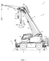
- crane 1 is a mobile crane that can be moved to an unspecified place.
- Crane 1 includes vehicle 2 and crane device 6.
- Vehicle 2 carries crane device 6.
- Vehicle 2 includes a plurality of wheels 3, and travels using engine 4 as a power source.
- Vehicle 2 is provided with outriggers 5.
- Outriggers 5 are composed of projecting beams hydraulically extendable on both sides of vehicle 2 in the width direction and hydraulic jack cylinders extendable in the direction vertical to the ground.
- Vehicle 2 can extend a workable region of crane 1 by extending outriggers 5 in the width direction of vehicle 2 and bringing the jack cylinders into contact with the ground.
- Crane device 6 lifts load (carried object) W with a wire rope.
- Crane device 6 includes swivel base 7, telescopic boom 8, jib 9, main hook block 10, sub hook block 11, luffing cylinder 12, main winch 13, main wire rope 14, sub winch 15, sub wire rope 16, camera 17, cabin 18, and the like.
- Swivel base 7 allows crane device 6 to swivel.
- Swivel base 7 is disposed on a frame of vehicle 2 via an annular bearing.
- the annular bearing is disposed such that its rotational center is vertical to the installation surface of vehicle 2.
- Swivel base 7 is configured to be rotatable in one and the other directions around the center of the annular bearing serving as a rotational center.
- swivel base 7 is rotated by hydraulic swivel motor 19 (see FIG. 2 ).
- Swivel base 7 is provided with swivel position detection sensor 21 (see FIG. 2 ) that detects the swivel position of swivel base 7.
- Telescopic boom 8 supports the wire rope such that load W can be lifted.
- Telescopic boom 8 is composed of a plurality of boom members, that is, base boom member 8a, second boom member 8b, third boom member 8c, fourth boom member 8d, fifth boom member 8e, and top boom member 8f.
- the boom members are inserted in a telescopic manner in order of the size of sectional surfaces.
- Telescopic boom 8 is configured to be extendible and retractable in the axial direction by moving the boom members by using telescopic cylinder 29 (see FIG. 2 ).
- Telescopic boom 8 is, at the base end of base boom member 8a, swingably provided on swivel base 7.
- Telescopic boom 8 is thus configured to be horizontally rotatable and swingable on the frame of vehicle 2.
- Telescopic boom 8 is provided with telescopic-boom-length detection sensor 22 that detects the telescopic boom length, and luffing-angle detection sensor 23 (see FIG. 2 ) that detects
- Jib 9 extends the lifting height and the operating radius of crane device 6.
- Jib 9 is held by jib supporting part 8g disposed in top boom member 8f of telescopic boom 8 such that the attitude of jib 9 is along top boom member 8f.
- the base end of jib 9 is configured to be able to be coupled to jib supporting part 8g of top boom member 8f.
- Main hook block 10 is for suspending load W.
- Main hook block 10 is provided with a plurality of hook sheaves around which main wire rope 14 is wound, and main hook 10a for suspending load W.
- Sub hook block 11 is for suspending load W.
- Sub hook block 11 is provided with sub hook 11a for suspending load W.
- Luffing cylinder 12 luffs up or down telescopic boom 8, and holds the attitude of telescopic boom 8.
- Luffing cylinder 12 includes a hydraulic cylinder made up of a cylinder part and a rod part. In luffing cylinder 12, an end of the cylinder part is swingably coupled to swivel base 7, and an end of the rod part is swingably coupled to base boom member 8a of telescopic boom 8.
- Luffing cylinder 12 has a configuration in which operating oil is supplied so as to push the rod part out of the cylinder part, so that base boom member 8a is luffed up, or the operating oil is supplied so as to push the rod part back into the cylinder part, so that base boom member 8a is luffed down.
- Main winch 13 pulls in (winds up) or lets out (winds out) main wire rope 14.
- Main winch 13 has a configuration in which a main drum around which main wire rope 14 is wound is rotated by a main hydraulic motor.
- Main winch 13 has a configuration in which the operating oil is supplied so as to rotate the main hydraulic motor in one direction, so that main wire rope 14 wound around the main drum is let out, or the operating oil is supplied so as to rotate the main hydraulic motor in the other direction, so that main wire rope 14 is pulled in around the main drum.
- Main winch 13 is provided with main-drum revolution detector 24 (see FIG. 2 ) for detecting the revolution of main winch 13 and main-wire tension detector 25 (see FIG. 2 ) for detecting the tension of main wire rope 14.
- Sub winch 15 pulls in or lets out sub wire rope 16.
- Sub winch 15 has a configuration in which a sub drum around which sub wire rope 16 is wound is rotated by a sub hydraulic motor.
- Sub winch 15 has a configuration in which the operating oil is supplied so as to rotate the sub hydraulic motor in one direction, so that sub wire rope 16 wound around the sub drum is let out, or the operating oil is supplied so as to rotate the sub hydraulic motor in the other direction, so that sub wire rope 16 is pulled in around the sub drum.
- Sub winch 15 is provided with sub-drum revolution detector 26 (see FIG. 2 ) for detecting the revolution of sub winch 15 and sub-wire tension detector 27 (see FIG. 2 ) for detecting the tension of sub wire rope 16.
- Camera 17 captures an image of load W and its surroundings.
- load W is suspended on main hook 10a, in which case camera 17 captures an image of main wire rope 14, main hook 10a, sling wire ropes 100 and 101, and load W.
- Camera 17 is provided on the leading end of top boom member 8f of telescopic boom 8 or on the leading end of jib 9.
- Camera 17 is disposed on top boom member 8f via an actuator for changing the attitude of camera 17.
- Camera 17 is configured to be swingable about an axis parallel to the swing axis of telescopic boom 8 which serves as the swing center. Accordingly, camera 17 is configured to be capable of capturing an image in a vertically-downward direction from its installation position regardless of the luffing angle of telescopic boom 8 or the luffing angle of jib 9.
- Cabin 18 covers an operator compartment. Cabin 18 is provided on swivel base 7 on a lateral side of telescopic boom 8. The operator compartment is provided inside cabin 18. The operator compartment is provided with a main manipulation tool for manipulating main winch 13, a sub manipulation tool for manipulating sub winch 15, an extension/retraction manipulation tool for manipulating telescopic boom 8, a steering for moving crane 1, hook position adjustment control switch 28 (see FIG. 2 ) for performing a hook position adjustment control, and the like.
- Crane 1 configured as described above is capable of moving crane device 6 to any position by causing vehicle 2 to travel.
- crane 1 is capable of extending the lifting height and/or the operating radius of crane device 6 by luffing up telescopic boom 8 to any luffing angle with luffing cylinder 12, extending telescopic boom 8 to any telescopic boom length, and/or coupling jib 9 to telescopic boom 8.
- FIG. 2 illustrates a configuration of a control system related to the hook position adjustment control.
- Crane 1 is provided with control device 20, for example, inside cabin 18.
- Control device 20 is connected to camera 17, swivel motor 19, swivel position detection sensor 21, telescopic cylinder 29, telescopic-boom-length detection sensor 22, luffing cylinder 12, luffing-angle detection sensor 23, main winch 13, main-drum revolution detector 24, main-wire tension detector 25, sub winch 15, sub-drum revolution detector 26, sub-wire tension detector 27, and hook position adjustment control switch 28.
- Wireless or wired connection can be used for connection between control device 20 and each component.
- Control device 20 controls a swivel operation, an extension/retraction operation, and a luffing operation of telescopic boom 8; a raising/lowering operation of main hook block 10 and sub hook block 11; and other various operations. Control device 20 also performs the hook position adjustment control of automatically adjusting main hook 10a or sub hook 11a to an optimum position before lift-off after slinging in order to reduce the occurrences of side pulling and/or a swing of load W. Control device 20 may have a configuration in which a CPU, ROM, RAM, HDD, and/or the like are connected to one another via a bus, or may also be configured to consist of a one-chip LSI or the like. Control device 20 stores therein a variety of programs and data for performing the hook position adjustment control.
- Control device 20 is provided with obtainment section 20a, storage section 20b, computation section 20c, determination section 20d, and output section 20e.
- Obtainment section 20a obtains information on each component connected to control device 20. Obtainment section 20a obtains an image captured by camera 17. In the present embodiment, obtainment section 20a always obtains images captured by camera 17 at predetermined intervals. Obtainment section 20a also obtains detection values of swivel position detection sensor 21, telescopic-boom-length detection sensor 22, luffing-angle detection sensor 23, main-drum revolution detector 24, main-wire tension detector 25, sub-drum revolution detector 26, and sub-wire tension detector 27. Obtainment section 20a also obtains a manipulation signal from hook position adjustment control switch 28.
- Storage section 20b stores therein information used for the hook position adjustment control; that is, storage section 20b stores therein the information obtained by obtainment section 20a, information computed by computation section 20c, a predetermined movement amount used by determination section 20d, and a result determined by determination section 20d. Storage section 20b also stores therein a program for performing the hook position adjustment control.
- Computation section 20c performs a computation required for the hook position adjustment control based on the information obtained by obtainment section 20a. For example, in a case where load W is suspended on main hook 10a, computation section 20c analyzes the image captured by camera 17 and computes the movement direction and movement amount of main hook 10a. Computation section 20c also computes the pulled-in amount or the let-out amount of main wire rope 14 from revolutions of main winch 13 detected by main-drum revolution detector 24.
- Determination section 20d performs a determination required for the hook position adjustment control based on the information obtained by obtainment section 20a, the predetermined movement amount stored in storage section 20b, and the computation result of computation section 20c. For example, in a case where load W is suspended on main hook 10a, determination section 20d determines whether or not main hook 10a is moved when main wire rope 14 is pulled in.
- Determination section 20d also determines whether main wire rope 14 is in a tensioned or relaxed state based on the tension of main wire rope 14 detected by main-wire tension detector 25. Determination section 20d also determines whether main wire rope 14 becomes relaxed or not, that is, whether main wire rope 14 is changed from the tensioned state to the relaxed state when the leading end of telescopic boom 8 is moved. The tensioned state can be determined when the tension detected by main-wire tension detector 25 is greater than or equal to a predetermined value, and the relaxed state can be determined when the tension is less than the predetermined value. Determination section 20d also determines based on the image captured by camera 17 whether or not sling wire ropes 100 and 101 are deflected.
- the tensioned state refers to a state in which main wire rope 14 is apparently in a linear state and is stretched owing to the elasticity of main wire rope 14.
- the relaxed state includes a state in which main wire rope 14 is apparently deflected and a state in which main wire rope 14 is in a linear state and is not stretched.
- Output section 20e outputs a signal for operating swivel motor 19, telescopic cylinder 29, luffing cylinder 12, main winch 13, and sub winch 15 based on the instructions from obtainment section 20a, computation section 20c, and determination section 20d.
- the hook position adjustment control is a control of automatically adjusting main hook 10a to an optimum position before lift-off after slinging in order to reduce the occurrences of side pulling and/or a swing of load W.
- the hook position adjustment control will be described with respect to four embodiments as examples.
- each embodiment will be described in which load W is suspended on main hook 10a by two-point suspension by using two-legged sling wire ropes 100 and 101.
- Sling wire ropes 100 and 101 are disposed so as not to be deflected in a state where main hook 10a is disposed on a vertical line passing through the center of gravity of load W.
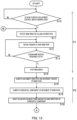
- FIG. 3 is a flowchart illustrating the operation of crane 1 related to the hook position adjustment control according to Embodiment 1.
- control device 20 stands by until obtainment section 20a obtains a manipulation signal from hook position adjustment control switch 28.
- obtainment section 20a obtains the manipulation signal from hook position adjustment control switch 28 at step S10. Accordingly, control device 20 determines that an instruction to perform the hook position adjustment control has been received, and proceeds to step S11 to perform the hook position adjustment control.
- control device 20 may proceed from step S10 to step S11 after confirming that load W is in a state before lift-off after slinging in order that an erroneous manipulation of hook position adjustment control switch 28 should not cause the hook position adjustment control to be performed.
- determination section 20d determines based on the image captured by camera 17 whether or not load W is in the state before lift-off after slinging. Then, when it is determined that load W is in the state before lift-off after slinging, control device 20 proceeds to step S11.
- control device 20 when it is determined that load W is not in the state before lift-off after slinging, control device 20 does not proceed to step S11, and outputs from output section 20e to a display section (not illustrated) an indication that the manipulation of hook position adjustment control switch 28 is invalid.
- step S11 output section 20e outputs to main winch 13 a signal for rotation in a pulling-in direction. Main wire rope 14 is thus pulled in. Subsequently, control device 20 proceeds to step S12 at which obtainment section 20a obtains a detection value from main-wire tension detector 25. Then, control device 20 proceeds to step S13 at which determination section 20d determines whether main wire rope 14 is in the tensioned or relaxed state.
- control device 20 When main wire rope 14 is determined to be in the relaxed state at step S13, control device 20 returns to step S12. Then, when at least one of sling wire ropes 100 and 101 is changed from the relaxed state to the tensioned state so that main wire rope 14 is changed from the relaxed state to the tensioned state at step S13, control device 20 proceeds from step S13 to step S14 at which output section 20e outputs a signal to stop revolution to main winch 13. Main winch 13 is thus stopped.
- first process P1 may be said to be a control by control device 20 to pull in main wire rope 14 to a position where main wire rope 14 is tensioned.
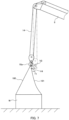
- Control device 20 proceeds from step S14 to step S15 at which computation section 20c analyzes the image captured by camera 17, and computes movement direction and movement amount V1 (see FIG. 5 ) of main hook 10a moved in first process P1. Subsequently, control device 20 proceeds to step S16 at which computation section 20c computes horizontal component V2 (see FIG. 5 ) from movement direction and movement amount V1 of main hook 10a.
- Control device 20 proceeds from step S16 to step S17 at which determination section 20d determines whether or not horizontal component V2 computed at step S16 is less than first movement amount T1 (see FIG. 5 ). When it is determined at step S17 that horizontal component V2 is less than first movement amount T1, control device 20 ends the hook position adjustment control.
- First movement amount T1 may be a value corresponding to little movement of main hook 10a in first process P1. This indicates that main hook 10a is located at a position where all sling wire ropes 100 and 101 are substantially in the tensioned state. It is possible to bring main hook 10a closer to a more appropriate position by setting smaller first movement amount T1.
- control device 20 proceeds to step S18 at which output section 20e outputs, to any necessary component among swivel motor 19, telescopic cylinder 29, and luffing cylinder 12, a signal for moving the leading end of telescopic boom 8 by the same amount in the same direction as horizontal component V2 computed at step S16.
- the movement amount of the leading end of telescopic boom 8 at step S18 does not have to be the same as horizontal component V2 of the movement amount of main hook 10a computed at step S16, and may be smaller or greater than horizontal component V2 as long as the movement amount of the leading end of telescopic boom 8 is in the same direction as horizontal component V2.
- second process P2 may be said to be a control by control device 20 to move the leading end of telescopic boom 8 in the same direction as horizontal component V2 of movement of main hook 10a in first process P1.
- control device 20 repeats first process P1 and second process P2 until the horizontal component of movement of main hook 10a is determined to be less than the first moving amount at step S17.
- Performance of the hook position adjustment control before lift-off after slinging thus makes it possible to automatically adjust the position of main hook 10a such that all sling wire ropes 100 and 101 are substantially brought into the tensioned state on the occasion of lift-off. Accordingly, it is possible to lift load W substantially vertically with respect to its center of gravity position on the occasion of lift-off so as to reduce occurrences of side pulling and/or a swing of load W. Moreover, the operator does not need to manually adjust the position of main hook 10a and/or the tension of sling wire ropes 100 and 101 before lift-off while checking the position of main hook 10a and/or the tension of sling wire ropes 100 and 101, so that it is possible to reduce the load on the operator.
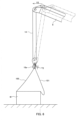
- FIG. 4 illustrates the state before lift-off after slinging, in which load W is slung from main hook 10a by sling wire ropes 100 and 101.
- main hook 10a is located at a position distant from the center of gravity of load W, and sling wire ropes 100 and 101 are in the relaxed state.
- crane 1 rotates main winch 13 in the pulling-in direction to pull in main wire rope 14.
- main winch 13 is stopped.
- sling wire rope 100 is in the tensioned state and sling wire rope 101 remains in the relaxed state.
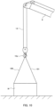
- crane 1 computes movement direction and movement amount V1 of main hook 10a moved during transition of from the state of FIG. 4 to the state of FIG. 5 , and computes horizontal component V2 of movement direction and movement amount V1. Then, after determining that horizontal component V2 is greater than or equal to first movement amount T1, crane 1 moves the leading end of telescopic boom 8 by the same amount in the same direction as horizontal component V2 as illustrated in FIG. 6 . Accordingly, main hook 10a is lowered, sling wire rope 100 is relaxed, and main wire rope 14 is bought into the relaxed state.
- crane 1 rotates main winch 13 in the pulling-in direction to pull in main wire rope 14.
- main winch 13 is stopped.
- sling wire rope 100 is in the tensioned state and sling wire rope 101 remains in the relaxed state.
- crane 1 computes movement direction and movement amount V3 of main hook 10a moved during transition of from the state of FIG. 6 to the state of FIG. 7 , and computes horizontal component V4 of movement direction and movement amount V3. Then, after determining that horizontal component V4 is greater than or equal to first movement amount T1, crane 1 moves the leading end of telescopic boom 8 by the same amount in the same direction as horizontal component V4 as illustrated in FIG. 8 . Accordingly, main hook 10a is lowered, sling wire rope 100 is relaxed, and main wire rope 14 is bought into the relaxed state.
- crane 1 rotates main winch 13 in the pulling-in direction to pull in main wire rope 14.
- main winch 13 is stopped.
- sling wire rope 100 is in the tensioned state and sling wire rope 101 comes to be in the relaxed state near the tensioned state.
- crane 1 computes movement direction and movement amount V5 of main hook 10a moved during transition of from the state of FIG. 8 to the state of FIG. 9 , and computes horizontal component V6 of movement direction and movement amount V5. Then, after determining that horizontal component V6 is less than first movement amount T1, crane 1 ends the hook position adjustment control. After this control, it becomes possible to lift load W substantially vertically with respect to its center-of-gravity position at the time of lift-off, so as to prevent the occurrences of side pulling and/or a swing of load W.
- FIG. 10 illustrates a state of an ideal end of the hook position adjustment control.
- main hook 10a is located at a position where all sling wire ropes 100 and 101 are in the tensioned state. It is possible to increase the accuracy of the hook position adjustment control to achieve a state close to the state of FIG. 10 by setting smaller first movement amount T1.
- FIG. 11 is a flowchart illustrating the operation of crane 1 related to a hook position adjustment control according to Embodiment 2.
- Embodiment 2 is different from Embodiment 1 in the timing and conditions for judging the end of the hook position adjustment control, and the other operations are the same between Embodiments 1 and 2. That is, in FIG. 11 , step S17 of FIG. 3 is removed, and step S20 and step S21 are provided following step S18. Steps S20 and S21 are included in the second process.
- step S20 computation section 20c analyzes an image captured by camera 17 and computes the movement amount of main hook 10a moved at step S18.
- Control device 20 proceeds from step S20 to step S21 at which determination section 20d determines whether or not the movement amount of main hook 10a computed at step S20 is less than second movement amount T2 (see FIG. 6 ).
- step S21 determines whether or not the movement amount of main hook 10a computed at step S20 is less than second movement amount T2 (see FIG. 6 ).
- control device 20 ends the hook position adjustment control. After this control, it becomes possible to lift load W substantially vertically with respect to its center-of-gravity position at the time of lift-off, so as to prevent the occurrences of side pulling and/or a swing of load W. Meanwhile, when it is determined at step S21 that the movement amount is greater than or equal to second movement amount T2, control device 20 returns to step S11.
- Second movement amount T2 may be a value corresponding to little movement of main hook 10a at step S18. This indicates that main hook 10a is located at a position where all sling wire ropes 100 and 101 are substantially in the tensioned state on the occasion of lift-off. It is possible to bring main hook 10a closer to a more appropriate position by setting smaller second movement amount T2.
- FIG. 12 is a flowchart illustrating the operation of crane 1 related to a hook position adjustment control according to Embodiment 3.
- Embodiment 3 is different from Embodiment 1 in the timing and conditions for judging the end of the hook position adjustment control, and the other operations are the same between Embodiments 1 and 3. That is, in FIG. 12 , step S17 of FIG. 3 is removed, and step S30 is provided following step S18. Step S30 is included in the second process.
- determination section 20d determines based on an image captured by camera 17 whether or not sling wire ropes 100 and 101 are deflected.
- control device 20 ends the hook position adjustment control. After this control, it becomes possible to lift load W substantially vertically with respect to its center-of-gravity position at the time of lift-off, so as to prevent the occurrences of side pulling and/or a swing of load W. Meanwhile, when it is determined at step S30 that sling wire rope 100 or 101 is deflected, control device 20 returns to step S11.
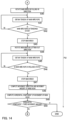
- FIGS. 13 and 14 are flowcharts illustrating the operation of crane 1 related to a hook position adjustment control according to Embodiment 4.
- FIGS. 13 and 14 are connected to each other by parts A and B.
- Embodiment 4 is different from Embodiment 1 in the timing and conditions for judging the end of the hook position adjustment control, and the other operations are the same between Embodiments 1 and 4. That is, in FIG. 13 , step S17 of FIG. 3 is removed, and steps S40 to S50 are provided following step S18. Steps S40 to S50 are included in the second process.
- step S40 output section 20e outputs to main winch 13 a signal for rotation in the pulling-in direction. Main wire rope 14 is thus pulled in. Subsequently, control device 20 proceeds to step S41 at which obtainment section 20a obtains a detection value from main-wire tension detector 25. Then, control device 20 proceeds to step S42 at which determination section 20d determines whether main wire rope 14 is in the tensioned or relaxed state.
- control device 20 When main wire rope 14 is determined to be in the relaxed state at step S42, control device 20 returns to step S41. Thereafter, when main wire rope 14 is changed from the relaxed state to the tensioned state at step S42, control device 20 proceeds from step S42 to step S43 at which output section 20e outputs a signal to stop revolution to main winch 13. Main winch 13 is thus stopped.
- control device 20 proceeds to step S44 at which output section 20e outputs to main winch 13 a signal for rotation in the letting-out direction. Main wire rope 14 is thus let out. Subsequently, control device 20 proceeds to step S45 at which obtainment section 20a obtains a detection value from main-wire tension detector 25. Then, control device 20 proceeds to step S46 at which determination section 20d determines whether main wire rope 14 is in the tensioned or relaxed state.
- control device 20 When main wire rope 14 is determined to be in the tensioned state at step S46, control device 20 returns to step S45. Thereafter, when main wire rope 14 is changed from the tensioned state to the relaxed state at step S46, control device 20 proceeds from step S46 to step S47 at which output section 20e outputs a signal to stop revolution to main winch 13. Main winch 13 is thus stopped.
- step S40 to step S47 such operations may be said to be a control by control device 20 to pull in main wire rope 14 to a position where main wire rope 14 is tensioned, and then let out main wire rope 14 to a position where main wire rope 14 is relaxed.
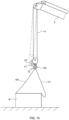
- FIG. 15 illustrates one example of the operations of crane 1 of from step S48 to step S50.
- Control device 20 proceeds from step S47 to step S48 at which computation section 20c analyzes an image captured by camera 17, and computes movement direction and movement amount V7 of movement of main hook 10a in the control of letting out main wire rope 14 at steps S44 to S47. Subsequently, control device 20 proceeds to step S49 at which computation section 20c computes horizontal component V8 from movement direction and movement amount V7 of main hook 10a.
- control device 20 proceeds to step S50 at which determination section 20d determines whether or not horizontal component V8 computed at step S49 is less than third movement amount T3.
- determination section 20d determines whether or not horizontal component V8 computed at step S49 is less than third movement amount T3.
- control device 20 ends the hook position adjustment control. After this control, it becomes possible to lift load W substantially vertically with respect to its center-of-gravity position at the time of lift-off, so as to prevent the occurrences of side pulling and/or a swing of load W. Meanwhile, when it is determined at step S50 that horizontal component V8 is greater than or equal to third movement amount T3, control device 20 returns to step S11.
- Third movement amount T3 may be a value corresponding to little movement of main hook 10a between steps S44 and S47. This indicates that main hook 10a is located at a position where all sling wire ropes 100 and 101 are substantially in the tensioned state on the occasion of lift-off. It is possible to bring main hook 10a closer to a more appropriate position by setting smaller third movement amount T3.
- the hook position adjustment control is performed when the hook position adjustment control switch is manipulated at step S10 of FIGS. 3 and 11 to 13 , but alternatively, control device 20 may perform the hook position adjustment control automatically before lift-off after slinging.
- the state before lift-off after slinging can be determined based on an image captured by camera 17, for example.
- the tension of main wire rope 14 is obtained at step S12 of FIGS. 3 and 11 to 13 , and it is determined at step S13 based on the value of the tension whether main wire rope 14 is in the tensioned or relaxed state.
- it may also be determined based on the image captured by camera 17 whether sling wire ropes 100 and 101 are in the relaxed or tensioned state.
- step S30 of FIG. 12 may be the same as those of steps S12 and S 13. That is, the process of step S30 of FIG. 12 may be a process in which obtainment section 20a obtains a detection value from main-wire tension detector 25 and determination section 20d determines whether main wire rope 14 is in the tensioned or relaxed state.
- control device 20 may be stored in a recording medium.
- a recording-medium reading device connected to control device 20 allows control device 20 to read the program from the recording medium to execute it.
- control device 20 may store in storage section 20b the program read from the recording medium, and may read the program from storage section 20b to execute it.
- control device 20 may also be stored in a server apparatus.
- a communication section connected to control device 20 allows control device 20 to receive the program from the server apparatus to execute it.
- control device 20 may store in storage section 20b the program received from the server apparatus, and may read the program from storage section 20b to execute it.
- the image captured by camera 17 is used to detect the states of main wire rope 14, main hook block 10, sling wire ropes 100 and 101, and load W.
- an Inertial Measurement Unit IMU
- a wire swing angle sensor or the like may also be used instead of camera 17.
- the present invention can be utilized for a control for cranes performed before lift-off.
Landscapes
- Engineering & Computer Science (AREA)
- Mechanical Engineering (AREA)
- Automation & Control Theory (AREA)
- Control And Safety Of Cranes (AREA)
Claims (10)
- Steuerungsverfahren für einen Kran (1), bei dem ein teleskopischer Kranarm (8), der wippen, ausfahren und einfahren kann, auf einer Schwenkbasis (7) angeordnet ist, ein Haken (10a) durch ein Drahtseil (14) an einem vorderen Ende des teleskopischen Kranarms (8) oder an einem vorderen Ende eines Auslegers (9), der auf dem teleskopischen Kranarm (8) angeordnet ist, aufgehängt ist, eine Last (W) an dem Haken (10a) durch eine Vielzahl von Drahtseilschlingen (100, 101) aufgehängt ist, eine Spannung des Drahtseils (14) durch einen Drahtspannungsdetektor (25) detektiert wird und eine Bewegungsrichtung des Hakens (10a) bestimmt wird,
dadurch gekennzeichnet, dass die Bewegungsrichtung des Hakens aus einem Bild bestimmt wird, das in einer vertikal nach unten gerichteten Richtung durch eine Kamera (17) aufgenommen wird, die an dem vorderen Ende des teleskopischen Kranarms (8) oder dem vorderen Ende des Auslegers (9) vorgesehen ist, wobei das Steuerungsverfahren umfasst:
eine Hakenpositionseinstellungssteuerung, bei der eine Steuervorrichtung (20) vor einem Abheben nach einem Umschlingen einen ersten Vorgang und einen zweiten Vorgang wiederholt, wobei der erste Vorgang eine Steuerung ist, um das Drahtseil (14) in eine Position einzuziehen, in der das Drahtseil (14) gespannt ist, und der zweite Vorgang eine Steuerung ist, um das vordere Ende des teleskopischen Kranarms (8) in eine selbe Richtung wie eine horizontale Bewegungskomponente des Hakens (10a), der im ersten Vorgang bewegt wurde, zu bewegen. - Steuerungsverfahren nach Anspruch 1, wobei der zweite Vorgang eine Steuerung enthält, um die Hakenpositionseinstellungssteuerung zu beenden, wenn die horizontale Komponente der Bewegung des Hakens (10a) kleiner als ein erster Bewegungsbetrag (T1) ist.
- Steuerungsverfahren nach Anspruch 1, wobei der zweite Vorgang eine Steuerung enthält, um die Hakenpositionseinstellungssteuerung zu beenden, wenn ein Bewegungsbetrag des Hakens (10a) kleiner als ein zweiter Bewegungsbetrag (T2) ist.
- Steuerungsverfahren nach Anspruch 1, wobei der zweite Vorgang eine Steuerung enthält, um die Hakenpositionseinstellungssteuerung zu beenden, wenn die Vielzahl der Drahtseilschlingen (100, 101) nicht ausgelenkt sind.
- Steuerungsverfahren nach Anspruch 1, wobei der zweite Vorgang eine Steuerung enthält, um das Drahtseil (14) in die Position einzuziehen, in der das Drahtseil (14) gespannt ist, dann das Drahtseil (14) in eine Position auszulassen, in der das Drahtseil (14) entspannt ist, und die Hakenpositionseinstellungssteuerung zu beenden, wenn ein horizontaler Bewegungsbetrag des Hakens (10a), der in der Steuerung zum Auslassen des Drahtseils (14) bewegt wurde, kleiner als ein dritter Bewegungsbetrag (T3) ist.
- Kran (1), umfassend:eine Schwenkbasis (7);einen teleskopischen Kranarm (8), der auf der Schwenkbasis (7) angeordnet ist, um wippen, ausfahren und einfahren zu können;ein Drahtseil (14), das von einem vorderen Ende des teleskopischen Kranarms (8) oder von einem vorderen Ende eines Auslegers (9), der an dem teleskopischen Kranarm (8) angeordnet ist, eingezogen oder ausgelassen wird;einen Haken (10a), der an dem Drahtseil (14) hängt;einen Drahtspannungsdetektor (25), der eine Spannung des Drahtseils (14) detektiert, gekennzeichnet durch,eine Kamera (17), die an dem vorderen Ende des teleskopischen Kranarms (8) oder dem vorderen Ende des Auslegers (9) vorgesehen ist und ein Bild in einer vertikal nach unten gerichteten Richtung aufnimmt, um eine Bewegungsrichtung des Hakens (10) zu bestimmen;eine Steuerungsvorrichtung (20), die eine Hakenpositionierungseinstellungssteuerung durchführt, bei der, bevor eine Last (W), die durch eine Vielzahl von Drahtseilschlingen (100, 101) an dem Haken (10a) aufgehängt ist, gehoben wird, ein erster Vorgang und ein zweiter Vorgang wiederholt werden, wobei der erste Vorgang eine Steuerung ist, um das Drahtseil (14) in eine Position einzuziehen, in der das Drahtseil (14) gespannt ist, und der zweite Vorgang eine Steuerung ist, um das vordere Ende des teleskopischen Kranarms (8) in eine selbe Richtung wie eine horizontale Bewegungskomponente des Hakens (10a), der im ersten Vorgang bewegt wurde, zu bewegen.
- Kran (1) nach Anspruch 6, wobei der zweite Vorgang eine Steuerung enthält, um die Hakenpositionseinstellungssteuerung zu beenden, wenn die horizontale Komponente der Bewegung des Hakens (10a) kleiner als ein erster Bewegungsbetrag (T1) ist.
- Kran (1) nach Anspruch 6, wobei der zweite Vorgang eine Steuerung enthält, um die Hakenpositionseinstellungssteuerung zu beenden, wenn ein Bewegungsbetrag des Hakens (10a) kleiner als ein zweiter Bewegungsbetrag (T2) ist.
- Kran (1) nach Anspruch 6, wobei der zweite Vorgang eine Steuerung enthält, um die Hakenpositionseinstellungssteuerung zu beenden, wenn die Vielzahl der Drahtseilschlingen (100, 101) nicht ausgelenkt sind.
- Kran (1) nach Anspruch 6, wobei der zweite Vorgang eine Steuerung enthält, um das Drahtseil (14) in die Position einzuziehen, in der das Drahtseil (1) gespannt ist, dann das Drahtseil (14) in eine Position auszulassen, in der das Drahtseil (14) entspannt ist, und die Hakenpositionseinstellungssteuerung zu beenden, wenn ein horizontaler Bewegungsbetrag des Hakens (14), der in der Steuerung zum Auslassen des Drahtseils (14) bewegt wurde, kleiner als ein dritter Bewegungsbetrag (T3) ist.
Priority Applications (1)
| Application Number | Priority Date | Filing Date | Title |
|---|---|---|---|
| EP20210511.0A EP3812336B1 (de) | 2017-10-04 | 2018-10-03 | Verfahren zur steuerung eines krans sowie kran |
Applications Claiming Priority (2)
| Application Number | Priority Date | Filing Date | Title |
|---|---|---|---|
| JP2017194454A JP6828650B2 (ja) | 2017-10-04 | 2017-10-04 | クレーンの制御方法及びクレーン |
| PCT/JP2018/037072 WO2019069991A1 (ja) | 2017-10-04 | 2018-10-03 | クレーンの制御方法及びクレーン |
Related Child Applications (2)
| Application Number | Title | Priority Date | Filing Date |
|---|---|---|---|
| EP20210511.0A Division EP3812336B1 (de) | 2017-10-04 | 2018-10-03 | Verfahren zur steuerung eines krans sowie kran |
| EP20210511.0A Division-Into EP3812336B1 (de) | 2017-10-04 | 2018-10-03 | Verfahren zur steuerung eines krans sowie kran |
Publications (3)
| Publication Number | Publication Date |
|---|---|
| EP3693322A1 EP3693322A1 (de) | 2020-08-12 |
| EP3693322A4 EP3693322A4 (de) | 2021-04-28 |
| EP3693322B1 true EP3693322B1 (de) | 2024-09-11 |
Family
ID=65995103
Family Applications (2)
| Application Number | Title | Priority Date | Filing Date |
|---|---|---|---|
| EP20210511.0A Active EP3812336B1 (de) | 2017-10-04 | 2018-10-03 | Verfahren zur steuerung eines krans sowie kran |
| EP18864302.7A Active EP3693322B1 (de) | 2017-10-04 | 2018-10-03 | Verfahren zur kransteuerung und kran |
Family Applications Before (1)
| Application Number | Title | Priority Date | Filing Date |
|---|---|---|---|
| EP20210511.0A Active EP3812336B1 (de) | 2017-10-04 | 2018-10-03 | Verfahren zur steuerung eines krans sowie kran |
Country Status (5)
| Country | Link |
|---|---|
| US (1) | US11702325B2 (de) |
| EP (2) | EP3812336B1 (de) |
| JP (1) | JP6828650B2 (de) |
| CN (2) | CN112010180B (de) |
| WO (1) | WO2019069991A1 (de) |
Families Citing this family (13)
| Publication number | Priority date | Publication date | Assignee | Title |
|---|---|---|---|---|
| DE102016005477A1 (de) * | 2016-05-03 | 2017-11-09 | Hycom B.V. | Ausgleichsvorrichtung zum Beibehalten von vorgebbaren Soll-Positionen einer handhabbaren Last |
| DE102019122796A1 (de) * | 2019-08-26 | 2021-03-04 | Liebherr-Werk Biberach Gmbh | Kran und Verfahren zum Steuern eines solchen Krans |
| CN110407103B (zh) * | 2019-08-27 | 2024-12-27 | 浙江三一装备有限公司 | 起重机控制方法、装置及起重机 |
| WO2021060463A1 (ja) * | 2019-09-25 | 2021-04-01 | 株式会社タダノ | 制御システム及び作業機 |
| CN116194400A (zh) * | 2020-07-29 | 2023-05-30 | 株式会社多田野 | 吊离地面控制装置及移动式起重机 |
| JP7650687B2 (ja) | 2021-03-17 | 2025-03-25 | 住友重機械建機クレーン株式会社 | クレーン |
| JP7485211B2 (ja) * | 2021-04-20 | 2024-05-16 | 株式会社タダノ | 巻層数の推定装置及びクレーン |
| CA3171550A1 (en) * | 2021-09-06 | 2023-03-06 | Manitou Italia S.R.L. | Telehandler with improved winch |
| CN114604759B (zh) * | 2022-01-24 | 2023-07-18 | 杭州大杰智能传动科技有限公司 | 一种具有导向结构的塔吊及其控制方法 |
| JP7409406B2 (ja) * | 2022-02-17 | 2024-01-09 | コベルコ建機株式会社 | クレーン制御方法、クレーン |
| FR3137908B1 (fr) * | 2022-07-12 | 2025-01-10 | Manitowoc Crane Group France | Procédé automatique pour la détermination lors d’un levage d’une position physique de fin de course d’un moufle d’une grue à tour |
| CN116374824B (zh) * | 2023-04-19 | 2024-10-15 | 中核四0四有限公司 | 一种容器的起竖控制参数的确定方法、装置及设备 |
| EP4714886A1 (de) * | 2024-09-20 | 2026-03-25 | Palfinger AG | Vorrichtung und verfahren zur steuerung einer bewegung einer hebevorrichtung |
Family Cites Families (9)
| Publication number | Priority date | Publication date | Assignee | Title |
|---|---|---|---|---|
| JPH0776490A (ja) * | 1993-09-09 | 1995-03-20 | Komatsu Ltd | クレーンの旋回自動停止制御装置 |
| JP4939701B2 (ja) | 2001-06-11 | 2012-05-30 | 株式会社タダノ | ブーム式クレーンを用いた荷物の地切り方法、および、装置 |
| JP2005306602A (ja) * | 2004-03-23 | 2005-11-04 | Tadano Ltd | ブーム式クレーンに用いられる荷物の地切装置 |
| JP2006056617A (ja) * | 2004-08-17 | 2006-03-02 | Tadano Ltd | ブーム式クレーンに用いられる荷物の地切装置 |
| JP2010235249A (ja) * | 2009-03-31 | 2010-10-21 | Tadano Ltd | クレーンの制御装置及びクレーン |
| CN101704483B (zh) * | 2009-11-27 | 2012-07-25 | 三一汽车制造有限公司 | 一种起重机工况识别系统、起重机控制系统及起重机 |
| EP3235773B8 (de) * | 2012-09-21 | 2023-09-20 | Tadano Ltd. | Vorrichtung zum erhalt von umgebungsinformationen für ein arbeitsfahrzeug |
| US9667923B2 (en) * | 2013-05-21 | 2017-05-30 | Tadano Ltd. | Camera attitude detection device and work region line display device |
| CN103663211B (zh) * | 2013-12-31 | 2015-08-19 | 太原重工股份有限公司 | 起重机及其控制方法 |
-
2017
- 2017-10-04 JP JP2017194454A patent/JP6828650B2/ja active Active
-
2018
- 2018-10-03 EP EP20210511.0A patent/EP3812336B1/de active Active
- 2018-10-03 CN CN202011037423.2A patent/CN112010180B/zh active Active
- 2018-10-03 WO PCT/JP2018/037072 patent/WO2019069991A1/ja not_active Ceased
- 2018-10-03 CN CN201880062971.5A patent/CN111148715A/zh active Pending
- 2018-10-03 EP EP18864302.7A patent/EP3693322B1/de active Active
- 2018-10-03 US US16/650,666 patent/US11702325B2/en active Active
Also Published As
| Publication number | Publication date |
|---|---|
| EP3812336A1 (de) | 2021-04-28 |
| CN112010180A (zh) | 2020-12-01 |
| JP6828650B2 (ja) | 2021-02-10 |
| CN111148715A (zh) | 2020-05-12 |
| US20200247647A1 (en) | 2020-08-06 |
| EP3812336B1 (de) | 2026-02-11 |
| JP2019064818A (ja) | 2019-04-25 |
| EP3693322A4 (de) | 2021-04-28 |
| US11702325B2 (en) | 2023-07-18 |
| WO2019069991A1 (ja) | 2019-04-11 |
| CN112010180B (zh) | 2023-04-14 |
| EP3693322A1 (de) | 2020-08-12 |
Similar Documents
| Publication | Publication Date | Title |
|---|---|---|
| EP3693322B1 (de) | Verfahren zur kransteuerung und kran | |
| EP2279978B1 (de) | Verfahren und Vorrichtung zum Spannen einer Trommel für ein Lastenhebezugseil | |
| US10138096B2 (en) | Automatic erection of a crane | |
| US12180043B2 (en) | Crane device, method for determining number of falls, and computer readable non-transitory recording medium | |
| CN106660762B (zh) | 移动式起重机 | |
| EP4067285A1 (de) | Überwachungsvorrichtung für windentrommel | |
| CN108883919A (zh) | 起重机 | |
| CN111747311B (zh) | 起重机 | |
| JP2019142679A (ja) | 吊荷監視装置 | |
| JP2018150088A (ja) | クレーン | |
| US20170210604A1 (en) | Compact stowable luffing jib for a crane | |
| JP2017193385A (ja) | クレーンのフック位置制御装置 | |
| JP2918720B2 (ja) | 移動式クレ−ンにおけるジブ起伏角一定制御装置 | |
| JP2018090372A (ja) | クレーンによるワークの搬送方法 | |
| JP7735815B2 (ja) | クレーン装置及び制御プログラム | |
| JPH0192198A (ja) | クレーンにおけるジブの装脱方法及び装置 | |
| EP4470961A1 (de) | Verfahren zum einziehen und ausklappen einer riemenscheibenvorrichtung | |
| JP7825971B2 (ja) | クレーンの振れ止め装置およびこれを備えたクレーン | |
| JP2019147682A (ja) | 移動式クレーン及びその玉掛け具長さ推定方法 | |
| JP2018095448A (ja) | 使用フック判定装置 | |
| JP7110753B2 (ja) | 起伏ロープの張力増加装置、および起伏ロープの張力増加方法 | |
| JP2002220188A (ja) | 荷の引き込み方法及び同装置 | |
| SU1404445A2 (ru) | Стреловой самоходный кран | |
| JP2020079128A (ja) | 過巻防止装置 | |
| JPH06183690A (ja) | クレーン装置 |
Legal Events
| Date | Code | Title | Description |
|---|---|---|---|
| STAA | Information on the status of an ep patent application or granted ep patent |
Free format text: STATUS: THE INTERNATIONAL PUBLICATION HAS BEEN MADE |
|
| PUAI | Public reference made under article 153(3) epc to a published international application that has entered the european phase |
Free format text: ORIGINAL CODE: 0009012 |
|
| STAA | Information on the status of an ep patent application or granted ep patent |
Free format text: STATUS: REQUEST FOR EXAMINATION WAS MADE |
|
| 17P | Request for examination filed |
Effective date: 20200416 |
|
| AK | Designated contracting states |
Kind code of ref document: A1 Designated state(s): AL AT BE BG CH CY CZ DE DK EE ES FI FR GB GR HR HU IE IS IT LI LT LU LV MC MK MT NL NO PL PT RO RS SE SI SK SM TR |
|
| AX | Request for extension of the european patent |
Extension state: BA ME |
|
| DAV | Request for validation of the european patent (deleted) | ||
| DAX | Request for extension of the european patent (deleted) | ||
| A4 | Supplementary search report drawn up and despatched |
Effective date: 20210326 |
|
| RIC1 | Information provided on ipc code assigned before grant |
Ipc: B66C 23/00 20060101AFI20210322BHEP Ipc: B66C 13/16 20060101ALI20210322BHEP Ipc: B66C 13/18 20060101ALI20210322BHEP Ipc: B66C 13/22 20060101ALI20210322BHEP Ipc: B66C 13/08 20060101ALI20210322BHEP Ipc: B66C 13/46 20060101ALI20210322BHEP |
|
| GRAP | Despatch of communication of intention to grant a patent |
Free format text: ORIGINAL CODE: EPIDOSNIGR1 |
|
| STAA | Information on the status of an ep patent application or granted ep patent |
Free format text: STATUS: GRANT OF PATENT IS INTENDED |
|
| INTG | Intention to grant announced |
Effective date: 20240411 |
|
| GRAS | Grant fee paid |
Free format text: ORIGINAL CODE: EPIDOSNIGR3 |
|
| GRAA | (expected) grant |
Free format text: ORIGINAL CODE: 0009210 |
|
| STAA | Information on the status of an ep patent application or granted ep patent |
Free format text: STATUS: THE PATENT HAS BEEN GRANTED |
|
| AK | Designated contracting states |
Kind code of ref document: B1 Designated state(s): AL AT BE BG CH CY CZ DE DK EE ES FI FR GB GR HR HU IE IS IT LI LT LU LV MC MK MT NL NO PL PT RO RS SE SI SK SM TR |
|
| REG | Reference to a national code |
Ref country code: GB Ref legal event code: FG4D |
|
| REG | Reference to a national code |
Ref country code: CH Ref legal event code: EP |
|
| REG | Reference to a national code |
Ref country code: DE Ref legal event code: R096 Ref document number: 602018074362 Country of ref document: DE |
|
| REG | Reference to a national code |
Ref country code: IE Ref legal event code: FG4D |
|
| REG | Reference to a national code |
Ref country code: LT Ref legal event code: MG9D |
|
| PG25 | Lapsed in a contracting state [announced via postgrant information from national office to epo] |
Ref country code: NO Free format text: LAPSE BECAUSE OF FAILURE TO SUBMIT A TRANSLATION OF THE DESCRIPTION OR TO PAY THE FEE WITHIN THE PRESCRIBED TIME-LIMIT Effective date: 20241211 |
|
| REG | Reference to a national code |
Ref country code: NL Ref legal event code: MP Effective date: 20240911 |
|
| PG25 | Lapsed in a contracting state [announced via postgrant information from national office to epo] |
Ref country code: GR Free format text: LAPSE BECAUSE OF FAILURE TO SUBMIT A TRANSLATION OF THE DESCRIPTION OR TO PAY THE FEE WITHIN THE PRESCRIBED TIME-LIMIT Effective date: 20241212 Ref country code: FI Free format text: LAPSE BECAUSE OF FAILURE TO SUBMIT A TRANSLATION OF THE DESCRIPTION OR TO PAY THE FEE WITHIN THE PRESCRIBED TIME-LIMIT Effective date: 20240911 |
|
| PG25 | Lapsed in a contracting state [announced via postgrant information from national office to epo] |
Ref country code: BG Free format text: LAPSE BECAUSE OF FAILURE TO SUBMIT A TRANSLATION OF THE DESCRIPTION OR TO PAY THE FEE WITHIN THE PRESCRIBED TIME-LIMIT Effective date: 20240911 |
|
| PG25 | Lapsed in a contracting state [announced via postgrant information from national office to epo] |
Ref country code: LV Free format text: LAPSE BECAUSE OF FAILURE TO SUBMIT A TRANSLATION OF THE DESCRIPTION OR TO PAY THE FEE WITHIN THE PRESCRIBED TIME-LIMIT Effective date: 20240911 |
|
| PG25 | Lapsed in a contracting state [announced via postgrant information from national office to epo] |
Ref country code: HR Free format text: LAPSE BECAUSE OF FAILURE TO SUBMIT A TRANSLATION OF THE DESCRIPTION OR TO PAY THE FEE WITHIN THE PRESCRIBED TIME-LIMIT Effective date: 20240911 |
|
| PG25 | Lapsed in a contracting state [announced via postgrant information from national office to epo] |
Ref country code: ES Free format text: LAPSE BECAUSE OF FAILURE TO SUBMIT A TRANSLATION OF THE DESCRIPTION OR TO PAY THE FEE WITHIN THE PRESCRIBED TIME-LIMIT Effective date: 20240911 Ref country code: RS Free format text: LAPSE BECAUSE OF FAILURE TO SUBMIT A TRANSLATION OF THE DESCRIPTION OR TO PAY THE FEE WITHIN THE PRESCRIBED TIME-LIMIT Effective date: 20241211 |
|
| PG25 | Lapsed in a contracting state [announced via postgrant information from national office to epo] |
Ref country code: RS Free format text: LAPSE BECAUSE OF FAILURE TO SUBMIT A TRANSLATION OF THE DESCRIPTION OR TO PAY THE FEE WITHIN THE PRESCRIBED TIME-LIMIT Effective date: 20241211 Ref country code: NO Free format text: LAPSE BECAUSE OF FAILURE TO SUBMIT A TRANSLATION OF THE DESCRIPTION OR TO PAY THE FEE WITHIN THE PRESCRIBED TIME-LIMIT Effective date: 20241211 Ref country code: LV Free format text: LAPSE BECAUSE OF FAILURE TO SUBMIT A TRANSLATION OF THE DESCRIPTION OR TO PAY THE FEE WITHIN THE PRESCRIBED TIME-LIMIT Effective date: 20240911 Ref country code: HR Free format text: LAPSE BECAUSE OF FAILURE TO SUBMIT A TRANSLATION OF THE DESCRIPTION OR TO PAY THE FEE WITHIN THE PRESCRIBED TIME-LIMIT Effective date: 20240911 Ref country code: GR Free format text: LAPSE BECAUSE OF FAILURE TO SUBMIT A TRANSLATION OF THE DESCRIPTION OR TO PAY THE FEE WITHIN THE PRESCRIBED TIME-LIMIT Effective date: 20241212 Ref country code: FI Free format text: LAPSE BECAUSE OF FAILURE TO SUBMIT A TRANSLATION OF THE DESCRIPTION OR TO PAY THE FEE WITHIN THE PRESCRIBED TIME-LIMIT Effective date: 20240911 Ref country code: ES Free format text: LAPSE BECAUSE OF FAILURE TO SUBMIT A TRANSLATION OF THE DESCRIPTION OR TO PAY THE FEE WITHIN THE PRESCRIBED TIME-LIMIT Effective date: 20240911 Ref country code: BG Free format text: LAPSE BECAUSE OF FAILURE TO SUBMIT A TRANSLATION OF THE DESCRIPTION OR TO PAY THE FEE WITHIN THE PRESCRIBED TIME-LIMIT Effective date: 20240911 |
|
| REG | Reference to a national code |
Ref country code: AT Ref legal event code: MK05 Ref document number: 1722539 Country of ref document: AT Kind code of ref document: T Effective date: 20240911 |
|
| PG25 | Lapsed in a contracting state [announced via postgrant information from national office to epo] |
Ref country code: NL Free format text: LAPSE BECAUSE OF FAILURE TO SUBMIT A TRANSLATION OF THE DESCRIPTION OR TO PAY THE FEE WITHIN THE PRESCRIBED TIME-LIMIT Effective date: 20240911 |
|
| PG25 | Lapsed in a contracting state [announced via postgrant information from national office to epo] |
Ref country code: PT Free format text: LAPSE BECAUSE OF FAILURE TO SUBMIT A TRANSLATION OF THE DESCRIPTION OR TO PAY THE FEE WITHIN THE PRESCRIBED TIME-LIMIT Effective date: 20250113 Ref country code: IS Free format text: LAPSE BECAUSE OF FAILURE TO SUBMIT A TRANSLATION OF THE DESCRIPTION OR TO PAY THE FEE WITHIN THE PRESCRIBED TIME-LIMIT Effective date: 20250111 |
|
| PG25 | Lapsed in a contracting state [announced via postgrant information from national office to epo] |
Ref country code: RO Free format text: LAPSE BECAUSE OF FAILURE TO SUBMIT A TRANSLATION OF THE DESCRIPTION OR TO PAY THE FEE WITHIN THE PRESCRIBED TIME-LIMIT Effective date: 20240911 Ref country code: SM Free format text: LAPSE BECAUSE OF FAILURE TO SUBMIT A TRANSLATION OF THE DESCRIPTION OR TO PAY THE FEE WITHIN THE PRESCRIBED TIME-LIMIT Effective date: 20240911 |
|
| PG25 | Lapsed in a contracting state [announced via postgrant information from national office to epo] |
Ref country code: EE Free format text: LAPSE BECAUSE OF FAILURE TO SUBMIT A TRANSLATION OF THE DESCRIPTION OR TO PAY THE FEE WITHIN THE PRESCRIBED TIME-LIMIT Effective date: 20240911 Ref country code: AT Free format text: LAPSE BECAUSE OF FAILURE TO SUBMIT A TRANSLATION OF THE DESCRIPTION OR TO PAY THE FEE WITHIN THE PRESCRIBED TIME-LIMIT Effective date: 20240911 |
|
| PG25 | Lapsed in a contracting state [announced via postgrant information from national office to epo] |
Ref country code: CZ Free format text: LAPSE BECAUSE OF FAILURE TO SUBMIT A TRANSLATION OF THE DESCRIPTION OR TO PAY THE FEE WITHIN THE PRESCRIBED TIME-LIMIT Effective date: 20240911 Ref country code: PL Free format text: LAPSE BECAUSE OF FAILURE TO SUBMIT A TRANSLATION OF THE DESCRIPTION OR TO PAY THE FEE WITHIN THE PRESCRIBED TIME-LIMIT Effective date: 20240911 |
|
| PG25 | Lapsed in a contracting state [announced via postgrant information from national office to epo] |
Ref country code: SK Free format text: LAPSE BECAUSE OF FAILURE TO SUBMIT A TRANSLATION OF THE DESCRIPTION OR TO PAY THE FEE WITHIN THE PRESCRIBED TIME-LIMIT Effective date: 20240911 Ref country code: IT Free format text: LAPSE BECAUSE OF FAILURE TO SUBMIT A TRANSLATION OF THE DESCRIPTION OR TO PAY THE FEE WITHIN THE PRESCRIBED TIME-LIMIT Effective date: 20240911 |
|
| REG | Reference to a national code |
Ref country code: CH Ref legal event code: PL |
|
| REG | Reference to a national code |
Ref country code: DE Ref legal event code: R097 Ref document number: 602018074362 Country of ref document: DE |
|
| PG25 | Lapsed in a contracting state [announced via postgrant information from national office to epo] |
Ref country code: MC Free format text: LAPSE BECAUSE OF FAILURE TO SUBMIT A TRANSLATION OF THE DESCRIPTION OR TO PAY THE FEE WITHIN THE PRESCRIBED TIME-LIMIT Effective date: 20240911 |
|
| PG25 | Lapsed in a contracting state [announced via postgrant information from national office to epo] |
Ref country code: DK Free format text: LAPSE BECAUSE OF FAILURE TO SUBMIT A TRANSLATION OF THE DESCRIPTION OR TO PAY THE FEE WITHIN THE PRESCRIBED TIME-LIMIT Effective date: 20240911 |
|
| PG25 | Lapsed in a contracting state [announced via postgrant information from national office to epo] |
Ref country code: BE Free format text: LAPSE BECAUSE OF NON-PAYMENT OF DUE FEES Effective date: 20241031 Ref country code: LU Free format text: LAPSE BECAUSE OF NON-PAYMENT OF DUE FEES Effective date: 20241003 |
|
| PLBE | No opposition filed within time limit |
Free format text: ORIGINAL CODE: 0009261 |
|
| STAA | Information on the status of an ep patent application or granted ep patent |
Free format text: STATUS: NO OPPOSITION FILED WITHIN TIME LIMIT |
|
| PG25 | Lapsed in a contracting state [announced via postgrant information from national office to epo] |
Ref country code: CH Free format text: LAPSE BECAUSE OF NON-PAYMENT OF DUE FEES Effective date: 20241031 |
|
| REG | Reference to a national code |
Ref country code: BE Ref legal event code: MM Effective date: 20241031 |
|
| 26N | No opposition filed |
Effective date: 20250612 |
|
| GBPC | Gb: european patent ceased through non-payment of renewal fee |
Effective date: 20241211 |
|
| PG25 | Lapsed in a contracting state [announced via postgrant information from national office to epo] |
Ref country code: SE Free format text: LAPSE BECAUSE OF FAILURE TO SUBMIT A TRANSLATION OF THE DESCRIPTION OR TO PAY THE FEE WITHIN THE PRESCRIBED TIME-LIMIT Effective date: 20240911 |
|
| PG25 | Lapsed in a contracting state [announced via postgrant information from national office to epo] |
Ref country code: GB Free format text: LAPSE BECAUSE OF NON-PAYMENT OF DUE FEES Effective date: 20241211 |
|
| PG25 | Lapsed in a contracting state [announced via postgrant information from national office to epo] |
Ref country code: FR Free format text: LAPSE BECAUSE OF NON-PAYMENT OF DUE FEES Effective date: 20241111 |
|
| PG25 | Lapsed in a contracting state [announced via postgrant information from national office to epo] |
Ref country code: IE Free format text: LAPSE BECAUSE OF NON-PAYMENT OF DUE FEES Effective date: 20241003 |
|
| PGFP | Annual fee paid to national office [announced via postgrant information from national office to epo] |
Ref country code: DE Payment date: 20251020 Year of fee payment: 8 |
|
| PG25 | Lapsed in a contracting state [announced via postgrant information from national office to epo] |
Ref country code: CY Free format text: LAPSE BECAUSE OF FAILURE TO SUBMIT A TRANSLATION OF THE DESCRIPTION OR TO PAY THE FEE WITHIN THE PRESCRIBED TIME-LIMIT; INVALID AB INITIO Effective date: 20181003 |
|
| PG25 | Lapsed in a contracting state [announced via postgrant information from national office to epo] |
Ref country code: HU Free format text: LAPSE BECAUSE OF FAILURE TO SUBMIT A TRANSLATION OF THE DESCRIPTION OR TO PAY THE FEE WITHIN THE PRESCRIBED TIME-LIMIT; INVALID AB INITIO Effective date: 20181003 |