EP3868613B1 - Rückhaltevorrichtung für fahrzeuginsassen - Google Patents
Rückhaltevorrichtung für fahrzeuginsassen Download PDFInfo
- Publication number
- EP3868613B1 EP3868613B1 EP19873381.8A EP19873381A EP3868613B1 EP 3868613 B1 EP3868613 B1 EP 3868613B1 EP 19873381 A EP19873381 A EP 19873381A EP 3868613 B1 EP3868613 B1 EP 3868613B1
- Authority
- EP
- European Patent Office
- Prior art keywords
- occupant
- pair
- seat
- airbag
- airbags
- Prior art date
- Legal status (The legal status is an assumption and is not a legal conclusion. Google has not performed a legal analysis and makes no representation as to the accuracy of the status listed.)
- Active
Links
Images



Classifications
-
- B—PERFORMING OPERATIONS; TRANSPORTING
- B60—VEHICLES IN GENERAL
- B60R—VEHICLES, VEHICLE FITTINGS, OR VEHICLE PARTS, NOT OTHERWISE PROVIDED FOR
- B60R21/00—Arrangements or fittings on vehicles for protecting or preventing injuries to occupants or pedestrians in case of accidents or other traffic risks
- B60R21/02—Occupant safety arrangements or fittings, e.g. crash pads
- B60R21/16—Inflatable occupant restraints or confinements designed to inflate upon impact or impending impact, e.g. air bags
- B60R21/20—Arrangements for storing inflatable members in their non-use or deflated condition; Arrangement or mounting of air bag modules or components
- B60R21/207—Arrangements for storing inflatable members in their non-use or deflated condition; Arrangement or mounting of air bag modules or components in vehicle seats
-
- B—PERFORMING OPERATIONS; TRANSPORTING
- B60—VEHICLES IN GENERAL
- B60R—VEHICLES, VEHICLE FITTINGS, OR VEHICLE PARTS, NOT OTHERWISE PROVIDED FOR
- B60R21/00—Arrangements or fittings on vehicles for protecting or preventing injuries to occupants or pedestrians in case of accidents or other traffic risks
- B60R21/02—Occupant safety arrangements or fittings, e.g. crash pads
- B60R21/16—Inflatable occupant restraints or confinements designed to inflate upon impact or impending impact, e.g. air bags
- B60R21/20—Arrangements for storing inflatable members in their non-use or deflated condition; Arrangement or mounting of air bag modules or components
- B60R21/215—Arrangements for storing inflatable members in their non-use or deflated condition; Arrangement or mounting of air bag modules or components characterised by the covers for the inflatable member
-
- B—PERFORMING OPERATIONS; TRANSPORTING
- B60—VEHICLES IN GENERAL
- B60R—VEHICLES, VEHICLE FITTINGS, OR VEHICLE PARTS, NOT OTHERWISE PROVIDED FOR
- B60R21/00—Arrangements or fittings on vehicles for protecting or preventing injuries to occupants or pedestrians in case of accidents or other traffic risks
- B60R21/02—Occupant safety arrangements or fittings, e.g. crash pads
- B60R21/16—Inflatable occupant restraints or confinements designed to inflate upon impact or impending impact, e.g. air bags
- B60R21/23—Inflatable members
- B60R21/231—Inflatable members characterised by their shape, construction or spatial configuration
- B60R21/23138—Inflatable members characterised by their shape, construction or spatial configuration specially adapted for side protection
-
- B—PERFORMING OPERATIONS; TRANSPORTING
- B60—VEHICLES IN GENERAL
- B60R—VEHICLES, VEHICLE FITTINGS, OR VEHICLE PARTS, NOT OTHERWISE PROVIDED FOR
- B60R21/00—Arrangements or fittings on vehicles for protecting or preventing injuries to occupants or pedestrians in case of accidents or other traffic risks
- B60R21/02—Occupant safety arrangements or fittings, e.g. crash pads
- B60R21/16—Inflatable occupant restraints or confinements designed to inflate upon impact or impending impact, e.g. air bags
- B60R21/23—Inflatable members
- B60R21/231—Inflatable members characterised by their shape, construction or spatial configuration
- B60R21/233—Inflatable members characterised by their shape, construction or spatial configuration comprising a plurality of individual compartments; comprising two or more bag-like members, one within the other
-
- B—PERFORMING OPERATIONS; TRANSPORTING
- B60—VEHICLES IN GENERAL
- B60R—VEHICLES, VEHICLE FITTINGS, OR VEHICLE PARTS, NOT OTHERWISE PROVIDED FOR
- B60R21/00—Arrangements or fittings on vehicles for protecting or preventing injuries to occupants or pedestrians in case of accidents or other traffic risks
- B60R21/02—Occupant safety arrangements or fittings, e.g. crash pads
- B60R21/16—Inflatable occupant restraints or confinements designed to inflate upon impact or impending impact, e.g. air bags
- B60R21/23—Inflatable members
- B60R21/231—Inflatable members characterised by their shape, construction or spatial configuration
- B60R21/2334—Expansion control features
- B60R21/2338—Tethers
-
- B—PERFORMING OPERATIONS; TRANSPORTING
- B60—VEHICLES IN GENERAL
- B60R—VEHICLES, VEHICLE FITTINGS, OR VEHICLE PARTS, NOT OTHERWISE PROVIDED FOR
- B60R21/00—Arrangements or fittings on vehicles for protecting or preventing injuries to occupants or pedestrians in case of accidents or other traffic risks
- B60R21/02—Occupant safety arrangements or fittings, e.g. crash pads
- B60R21/16—Inflatable occupant restraints or confinements designed to inflate upon impact or impending impact, e.g. air bags
- B60R2021/161—Inflatable occupant restraints or confinements designed to inflate upon impact or impending impact, e.g. air bags characterised by additional means for controlling deployment trajectory
-
- B—PERFORMING OPERATIONS; TRANSPORTING
- B60—VEHICLES IN GENERAL
- B60R—VEHICLES, VEHICLE FITTINGS, OR VEHICLE PARTS, NOT OTHERWISE PROVIDED FOR
- B60R21/00—Arrangements or fittings on vehicles for protecting or preventing injuries to occupants or pedestrians in case of accidents or other traffic risks
- B60R21/02—Occupant safety arrangements or fittings, e.g. crash pads
- B60R21/16—Inflatable occupant restraints or confinements designed to inflate upon impact or impending impact, e.g. air bags
- B60R21/23—Inflatable members
- B60R21/231—Inflatable members characterised by their shape, construction or spatial configuration
- B60R21/233—Inflatable members characterised by their shape, construction or spatial configuration comprising a plurality of individual compartments; comprising two or more bag-like members, one within the other
- B60R2021/23324—Inner walls crating separate compartments, e.g. communicating with vents
-
- B—PERFORMING OPERATIONS; TRANSPORTING
- B60—VEHICLES IN GENERAL
- B60R—VEHICLES, VEHICLE FITTINGS, OR VEHICLE PARTS, NOT OTHERWISE PROVIDED FOR
- B60R21/00—Arrangements or fittings on vehicles for protecting or preventing injuries to occupants or pedestrians in case of accidents or other traffic risks
- B60R21/02—Occupant safety arrangements or fittings, e.g. crash pads
- B60R21/16—Inflatable occupant restraints or confinements designed to inflate upon impact or impending impact, e.g. air bags
- B60R21/23—Inflatable members
- B60R21/231—Inflatable members characterised by their shape, construction or spatial configuration
- B60R21/233—Inflatable members characterised by their shape, construction or spatial configuration comprising a plurality of individual compartments; comprising two or more bag-like members, one within the other
- B60R2021/23324—Inner walls crating separate compartments, e.g. communicating with vents
- B60R2021/23332—Inner walls crating separate compartments, e.g. communicating with vents using independent bags, one within the other
-
- B—PERFORMING OPERATIONS; TRANSPORTING
- B60—VEHICLES IN GENERAL
- B60R—VEHICLES, VEHICLE FITTINGS, OR VEHICLE PARTS, NOT OTHERWISE PROVIDED FOR
- B60R21/00—Arrangements or fittings on vehicles for protecting or preventing injuries to occupants or pedestrians in case of accidents or other traffic risks
- B60R21/02—Occupant safety arrangements or fittings, e.g. crash pads
- B60R21/16—Inflatable occupant restraints or confinements designed to inflate upon impact or impending impact, e.g. air bags
- B60R21/23—Inflatable members
- B60R21/231—Inflatable members characterised by their shape, construction or spatial configuration
- B60R21/2334—Expansion control features
- B60R21/2338—Tethers
- B60R2021/23386—External tether means
-
- B—PERFORMING OPERATIONS; TRANSPORTING
- B60—VEHICLES IN GENERAL
- B60R—VEHICLES, VEHICLE FITTINGS, OR VEHICLE PARTS, NOT OTHERWISE PROVIDED FOR
- B60R21/00—Arrangements or fittings on vehicles for protecting or preventing injuries to occupants or pedestrians in case of accidents or other traffic risks
- B60R21/02—Occupant safety arrangements or fittings, e.g. crash pads
- B60R21/16—Inflatable occupant restraints or confinements designed to inflate upon impact or impending impact, e.g. air bags
- B60R21/23—Inflatable members
- B60R21/231—Inflatable members characterised by their shape, construction or spatial configuration
- B60R21/2334—Expansion control features
- B60R21/2338—Tethers
- B60R2021/23386—External tether means
- B60R2021/23388—External tether means having ends which are movable or detachable during deployment
Definitions
- the present invention relates to an occupant restraining device that restrains an occupant sitting on a seat of a vehicle.
- Airbag devices have generally become standard equipment in vehicles in recent years.
- An airbag device is a safety device which is operated in case of an emergency such as a vehicle collision and, for example, expands and deploys to protect the occupant.
- a tensile cloth is provided that is tensioned during expansion and deployment of the airbag and extends between both sides of the airbag and the seat cushion.
- Patent Document 1 WO 2016-039160
- an occupant restraining device comprising all features of the preamble is known form the document JP 2009 029182 A , in which a pair of airbags are stowed in both the left and right sides of the seat back with a pair of tensile cloths stowed within the seatback along the side of the pair of airbags, wherein the pair of tensile cloths are deployed along the side of the seat on the side opposite to the occupant.
- Patent Document 1 JP 2009 029182 A .
- Further restraining devices are known from one of the documents JP 2016 007901 A , JP 2016 078768 A , WO 2017/199851 A1 , JP 2013 220714A , JP 2014 051138A or JP 2017 074850 A .
- an object of the present invention is to provide an occupant restraining device capable of further improving occupant restraining performance with a structure having tensile cloth that deploys on the side part of a seat during expansion and deployment of an airbag.
- a typical configuration of the occupant restraining device of the present invention includes a pair of airbags that are stowed in both the left and right sides of a seat back portion of the seat and expands and deploys to a side of an occupant sitting on the , wherein the pair of airbags stowed in the seatback of the seat that inflate and deploy respectively on both sides of an occupant seated in the seat; and a pair of tensile cloths stowed from within the seatback of the seat to within the seat cushion along the side of the pair of airbags on the side opposite the occupant respectively, wherein the pair of tensile cloths are deployed along the side of the seat on the side opposite the occupant by the expansion and deployment of the pair of airbags and are stretched from the seatback to the seat cushion to retain surface of the pair of, with an inner bag that is stowed inside at least a first airbag of the pair of airbags and is connected to at least the first airbag and expand
- the expanded and deployed airbag is biased towards the occupant by the tensile cloth. This enables suppressing movement of the airbag in a direction away from the occupant and restraining of the occupant more securely.
- an inner bag is stowed inside the airbag.
- the inner bag has a smaller volume than the airbag being contained within the airbag, and therefore requires less gas to expand and deploy. Therefore, the inner bag completes expansion earlier than the airbag.
- the torso of the occupant can be restrained quickly in the event of a collision, especially a side impact, and the occupant restraining performance can be further improved.
- another configuration of the occupant restraining device is an occupant restraining device that restrains an occupant sitting on a seat of a vehicle, comprising a pair of airbags that are stowed in both the left and right sides of a seatback portion of the seat and expands and deploys to a side of an occupant sitting on the seat; and the pair of airbags stowed in the seatback of the seat that inflate and deploy respectively on both sides of an occupant seated on the seat and a pair of tensile cloths stowed from within the seatback of the seat to within the seat cushion along the side of the pair of airbags on the side opposite the occupant respectively, wherein the pair of tensile cloths are deployed along the side of the seat on the side opposite the occupant by the expansion and deployment of the pair of airbags and are stretched from the seatback to the seat cushion to retain the surfaces of the pair of airbags, wherein A partition wall arranged inside at
- the expanded and deployed airbag is again biased towards the occupant by the tensile cloth. This enables suppressing movement of the airbag in a direction away from the occupant and restraining of the occupant more securely.
- the interior of the airbag is partitioned into two spaces in the front-rear direction by a partition wall.
- the space in front of the partition wall is hereinafter referred to as the front chamber
- the space behind the partition wall is referred to as the rear chamber.
- the rear chamber is positioned to the side of the torso of the occupant and expands and deploys before the front chamber.
- the partition wall is arranged at or behind a position overlapping at least a first of the pair of tensile cloths in a side view when at least a first airbag expands and deploys.
- At least a first airbag described above may include an airbag positioned on the near side of the occupant. This enables suitable prevention of contact between the occupant and the vehicle body in the event of a side collision. Note, of the left and right sides of the occupant seated in a seat, the near side is the side on the vehicle body side, and of the left and right sides of the occupant seated in a seat, the far side is the side that is not on the vehicle body side.
- the pair of tensile cloths described above may be deployed along the side of the seat by breaking the seat surface skin.
- the occupant restraining device may have a pair of cases arranged along the side of the seat for stowing the pair of airbags and the pair of tensile cloths, and the pair of tensile cloths may be deployed from the pair of cases to the side of the seat.
- an occupant restraining device capable of further improving occupant restraining performance in a configuration provided with a tensile cloth that is deployed along the side of a seat during expansion and deployment of an airbag can be provided.
- any diagrams used in descriptions below will indicate the front, rear, left, right, up, and down directions based on the occupant as described above as Fr, Rr, L, R, Up, and Down.
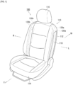
- FIG. 1 is a diagram illustrating an occupant restraining device 100 according to embodiment 1.
- FIG. 1 illustrates the members stowed inside a seat 110 using hidden lines.
- the seat is illustrated with the airbag not expanded and deployed.
- the occupant restraining device 100 of the present embodiment is a device for restraining an occupant that is seated in the seat 110.
- the occupant restraining device 100 of embodiment 1 includes the seat 110, airbags 120a and 120b, left side tensile cloth 130a, and right side tensile cloth 130b of the vehicle (full vehicle not shown).
- the seat 110 includes a seatback 112 that supports the upper body of the occupant.
- a seat cushion 114 is provided below the seatback 112 on which the occupant sits.
- a headrest 116 is provided above the seatback that supports the head of the occupant.
- the pair of airbags 120a and 120b are stowed in both the left and right sides of the seatback 112 of the seat 110, which are covered by covers 118.
- the cover 118 includes a part of the outer skin of the seat 110.
- the pair of airbags 120a and 120b expand and deploy on both sides of the occupant seated in the seat 110 during a collision or the like of the vehicle.
- a structure where a cover 118 is integrated with the surface skin of the seat is illustrated but is not limited thereto, and the seat surface skin and cover can be separate.
- a pair of tensile cloths 130a and 130b are provided for each of the airbags 120a and 120b in this embodiment.
- the pair of tensile cloths 130a and 130b are respectively stored from inside the seatback 112 of the seat 110 to in the seat cushion 114 through the side of the stored pair of airbags 120a and 120b opposite the occupant.
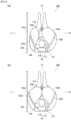
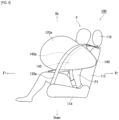
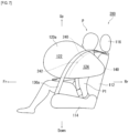
- FIG. 2 , FIG. 3 and FIG. 4 are diagrams that illustrate the state of the airbags 120a and 120b of FIG. 1 during expansion and deployment.
- FIGS. 2(a) and 2(b) illustrate a state in which an occupant P is seated in the seat 110 illustrated in FIG. 1 , and a state where the airbags 120a and 120b are expanded and deployed is observed from above.
- FIG. 3 and FIG. 4 illustrate a state where an occupant P is seated in the seat 110 illustrated in FIG. 1 , and a state where the airbag 120a having been expanded and deployed is observed from the side.
- a vehicle body 102 is positioned on the left side. Accordingly, with regards to the left/right pair of airbags 120a and 120b, the airbag 120a on the left side is an airbag positioned on the near side and the airbag 120b on the right side is an airbag positioned on the far side.
- the inner bag 140 is housed in a rearward area inside the left airbag 120a (nearside airbag) facing the vehicle body side 102 of the left and right pairs of airbags 120a and 120b.
- the inner bag 140 has a smaller volume than the airbag 120a because it is stowed inside the airbag 120a. Therefore, expansion and deployment of the inner bag 140 is completed with a smaller amount of gas than that for the airbag 120a.
- An inner vent 142 is formed in the inner bag 140.
- the airbag 120a and the inner bag 140 are connected at the inner vent 142.
- gas is supplied to the inner bag 140 by an inflator (not illustrated). Therefore, the inner bag 140 completes expansion and deployment before the airbag 120a, as illustrated in FIG. 2(a) .
- the inner bag 140 expands and deploys to the side of the torso P1 (see FIG. 3 ) of the occupant P inside the airbag 120a because the inner bag 140 is arranged in the rearward area of the airbag 120a.
- gas then flows out of the inner vent 142 of the inner bag 140, supplying gas to the airbag 120a. This completes expansion and deployment of the airbag 120a, as illustrated in FIG. 2(b) .
- the inner bag 140 which has a smaller capacity than the airbag 120a, expands and deploys to the side of the torso P1 of the occupant P before the airbag 120a. This allows the torso P1 of the occupant P to be restrained quickly during a collision. Therefore, high occupant restraining performance can be obtained by the occupant restraining device 100.
- the front end 140a of the inner bag 140 is arranged at a position overlapping with the tensile cloth 130a in a side view when the airbag 120a is expanded and deployed.
- the tensile cloth 130a does not stretch across the inner bag 140, and the tensile cloth 130a does not inhibit the expansion and deployment of the inner bag 140. Therefore, the effects described above can reliably be obtained.
- a configuration in which the front end 140a of the inner bag 140 is arranged at a position overlapping with the tensile cloth 130a is illustrated, but is not limited thereto.
- the same effect can be obtained in a configuration in which the front end 140a of the inner bag 140 is arranged behind the position where the inner bag 140 overlaps with the tensile cloth 130a, that is, in a configuration in which the inner bag 140 and the tensile cloth 130a do not overlap in a side view.
- the tensile cloths 130a and 130b deploy to the side of the seat 110 by breaking open the surface skin of the seat 110. Therefore, the tensile cloths 130a and 130b are stretched from the seatback 112 to the seat cushion 114, and the surfaces opposite the occupant P of the airbags 120a and 120b, respectively, are retained by the tensile cloths 130a and 130b. Furthermore, the airbags 120a and 120b are then biased against the occupant P by the tensile cloths 130a and 130b, thereby enhancing the occupant restraining performance of the airbags 120a and 120b.
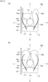
- FIG. 5 , FIG. 6 , and FIG. 7 are diagrams illustrating an occupant restraining device 200 in embodiment 2.
- FIGS. 5(a) and (b) illustrate a state in which an occupant P is seated in the seat 110 illustrated in FIG. 1 , and a state where the airbags 120a and 120b having been expanded and deployed is observed from above.
- FIG. 6 and FIG. 7 illustrate a state where an occupant P is seated in the seat 110 illustrated in FIG. 1 , and the state where the airbag 120a having been expanded and deployed is observed from the side. Note that all components in embodiment 2 that are common with those of embodiment 1 are given the same sign and their explanations are omitted.
- a partition wall 240 is provided inside the airbag 120a instead of the inner bag 140 in embodiment 1.
- the partition wall 240 demarcates the interior of the airbag 120a into front and rear sections.
- the space in front of the partition wall 240 is hereinafter referred to as the front chamber 122
- the space behind the partition wall 240 is referred to as the rear chamber 124.
- a connecting hole 242 is formed in the partition wall 240. This connects the front chamber 122 to the rear chamber 124.
- the rear chamber 124 is arranged to the side of the torso P1 of the occupant P.
- gas is supplied to the rear chamber 124 by an inflator (not illustrated). Therefore, with the airbag 120a, the rear chamber 124 completes expansion and deployment before the front chamber 122, as illustrated in FIG. 5 (a) .
- the rear chamber 124 expands and deploys to the side of the torso P1 of the occupant P (see FIG. 3 ), thereby quickly restraining the torso P1 of the occupant P in the event of a collision. Accordingly, high occupant restraining performance can be achieved by the occupant restraining device 200 during a collision, especially during a side impact.
- the partition wall 240 is arranged at a position overlapping with the tensile cloth 130a in a side view when the airbag 120a is expanded and deployed.
- the tensile cloth 130a does not stretch across the rear chamber 124, and the tensile cloth 130a does not inhibit expansion and deployment of the rear chamber 124. Therefore, the effects described above can reliably be obtained.
- a configuration in which the partition wall 240 is arranged at a position overlapping with the tensile cloth 130a is illustrated, but is not limited thereto.
- the same effect can be obtained in a configuration in which the partition wall 240 is arranged rearward of the position where it overlaps with the tensile cloth 130a, in other words, in a configuration in which the rear chamber 124 and the tensile cloth 130a do not overlap in a side view.
- both the occupant restraining device 100 of embodiment 1 and the occupant restraining device 200 of embodiment 2 illustrate configurations in which the left side airbag 120a located on the near side has an inner bag 140 or a partition wall 240.
- FIG. 8 is a diagram illustrating another example of an occupant restraining device.
- the occupant restraining device 300 illustrated in FIG. 8 includes cases 118a and 118b arranged along the side of the seat 110.
- Case 118a is the case where airbags 120a and 120b are stowed and case 118b is the case where tensile cloths 130a and 130b are stowed.
- the tensile cloths 130a and 130b are deployed from the case 118b to the side of the seat 110 during expansion and deployment of the airbags 120a and 120b.
- This configuration will also provide the same effects as the occupant restraining device 100 described above.
- the present invention can be used in an occupant restraining device that restrains an occupant sitting on a seat of a vehicle.
- P1...torso 100...occupant restraining device, 102...vehicle body, 110...seat, 112...seatback, 114...seat cushion, 116...head rest, 118...cover, 118a and 118b...cases, 120a...airbag, 120b...airbag, 122...front chamber, 124...rear chamber, 130a...tensile cloth, 130b...tensile cloth, 140...inner bag, 140a...front end, 142... Inner vent, 200...occupant restraining device, 240...partition wall, 242...connecting hole, 300...occupant restraining device, P... occupant
Landscapes
- Engineering & Computer Science (AREA)
- Mechanical Engineering (AREA)
- Air Bags (AREA)
Claims (5)
- Insassenrückhaltevorrichtung (100), die einen Insassen schützt, der in einem Sitz (110) eines Fahrzeugs sitzt, umfassend:ein Paar von Airbags (120a, 120b), die sowohl auf der linken als auch auf der rechten Seite eines Rückenlehnenabschnitts (112) des Sitzes (110) verstaut sind und sich auf einer Seite eines Insassen, der auf dem Sitz (110) sitzt, ausdehnen und entfalten; unddas Paar von Airbags (120a, 120b), die in der Rückenlehne (112) des Sitzes (110) verstaut sind, die sich auf beiden Seiten eines Insassen, der in dem Sitz (110) sitzt, aufblasen beziehungsweise entfalten;ein Paar von Zugtüchern (130a, 130b), die von innerhalb der Rückenlehne (112) des Sitzes (110) bis innerhalb des Sitzpolsters (114) entlang der Seite des Paars von Airbags (120a, 120b) auf der Seite gegenüber dem Insassen jeweils verstaut sind; wobeidas Paar von Zugtüchern (130a, 130b) entlang der Seite des Sitzes (110) auf der Seite gegenüber des Insassen durch die durch die Ausdehnung und Entfaltung des Paars von Airbags (120a, 120b) entfaltet werden und von der Rückenlehne (112) zu dem Sitzpolster (114) gedehnt werden, um die Oberfläche des Paars von Airbags (120a, 120b) zu sichern,gekennzeichnet dadurch,einen Innensack (140), der im Inneren mindestens eines ersten Airbags des Paars von Airbags(120a, 120b) verstaut ist und mit mindestens dem ersten Airbag verbunden ist und sich zu der Seite des Rumpfes (P1) des Insassen im Inneren mindestens des ersten Airbags ausdehnt und entfaltet; wobeider Innensack (140) seine Ausdehnung und Entfaltung vor mindestens einem ersten Airbag abschließt,wobei das vordere Ende (140a) des Innensacks (140) an oder hinter einer Position angeordnet ist, die mindestens ein erstes des Paars von Zugtüchern (130a, 130b) in einer Seitenansicht überlappt, wenn mindestens ein erster Airbag ausgedehnt und entfaltet ist.
- Insassenrückhaltevorrichtung (100), die einen Insassen schützt, der in einem Sitz (110) eines Fahrzeugs sitzt, umfassend:ein Paar von Airbags (120a, 120b), die sowohl auf der linken als auch auf der rechten Seite eines Rückenlehnenabschnitts (112) des Sitzes (110) verstaut sind und sich auf einer Seite eines Insassen, der auf dem Sitz (110) sitzt, ausdehnen und entfalten; unddas Paar von Airbags (120a, 120b), die in der Rückenlehne (112) des Sitzes (110) verstaut sind, die sich auf beiden Seiten eines Insassen, der in dem Sitz (110) sitzt, aufblasen beziehungsweise entfalten;ein Paar von Zugtüchern (130a, 130b), die von innerhalb der Rückenlehne (112) des Sitzes (110) bis innerhalb des Sitzpolsters (114) entlang der Seite des Paars von Airbags (120a, 120b) auf der Seite gegenüber dem Insassen jeweils verstaut sind; wobeidas Paar von Zugtüchern (130a, 130b) entlang der Seite des Sitzes (110) auf der Seite gegenüber des Insassen durch die durch die Ausdehnung und Entfaltung des Paars von Airbags (120a, 120b) entfaltet werden und von der Rückenlehne (112) zu dem Sitzpolster (114) gedehnt werden, um die Oberfläche des Paars von Airbags (120a, 120b) zu sichern,gekennzeichnet dadurch,eine Trennwand (240), die innerhalb von mindestens einem ersten des Paars von Airbags (120a, 120b) angeordnet ist und mindestens den ersten Airbag in einen vorderen und einen hinteren Abschnitt unterteilt;ein Verbindungsloch (242), das in der Trennwand (240) ausgebildet ist; und mindestens der erste Airbag eine Ausdehnung und Entfaltung des Raums hinter der Trennwand (240) vor dem Raum vor der Trennwand (240) abschließt,wobei die Trennwand (240) an oder hinter einer Position angeordnet ist, die ein erstes des Paars von Zugtüchern (130a, 130b) in einer Seitenansicht überlappt, wenn mindestens ein erster Airbag ausgedehnt und entfaltet ist.
- Insassenrückhaltevorrichtung (100) nach einem der Ansprüche 1 oder 2, wobei mindestens der erste Airbag einen Airbag einschließt, der auf der Seite nahe dem Insassen positioniert ist.
- Insassenrückhaltevorrichtung (100) nach einem der Ansprüche 1 bis 3, wobei das Paar von Zugtüchern (130a, 130b) entlang der Seite des Sitzes (110) durch Aufbrachen der Oberflächenhaut des Sitzes (110) entfaltet werden.
- Insassenrückhaltevorrichtung (100) nach einem der Ansprüche 1 bis 4, umfassend:ein Paar von Gehäusen (118a, 118b), in denen das Paar von Airbags (120a, 120b) und das Paar von Zugtüchern (130a, 130b) verstaut sind, die auf der Seite des Sitzes (110) angeordnet, wobeisich das Paar von Zugtüchern (130a, 130b) von dem Paar von Gehäusen (118a, 118b) entlang der Seite des Sitzes (110) entfalten.
Applications Claiming Priority (2)
| Application Number | Priority Date | Filing Date | Title |
|---|---|---|---|
| JP2018194968 | 2018-10-16 | ||
| PCT/JP2019/037529 WO2020080050A1 (ja) | 2018-10-16 | 2019-09-25 | 乗員拘束装置 |
Publications (3)
| Publication Number | Publication Date |
|---|---|
| EP3868613A1 EP3868613A1 (de) | 2021-08-25 |
| EP3868613A4 EP3868613A4 (de) | 2022-07-20 |
| EP3868613B1 true EP3868613B1 (de) | 2024-10-30 |
Family
ID=70284586
Family Applications (1)
| Application Number | Title | Priority Date | Filing Date |
|---|---|---|---|
| EP19873381.8A Active EP3868613B1 (de) | 2018-10-16 | 2019-09-25 | Rückhaltevorrichtung für fahrzeuginsassen |
Country Status (6)
| Country | Link |
|---|---|
| US (1) | US11433843B2 (de) |
| EP (1) | EP3868613B1 (de) |
| JP (1) | JP7038229B2 (de) |
| KR (1) | KR102569645B1 (de) |
| CN (1) | CN112867641B (de) |
| WO (1) | WO2020080050A1 (de) |
Families Citing this family (4)
| Publication number | Priority date | Publication date | Assignee | Title |
|---|---|---|---|---|
| FR3126372B1 (fr) * | 2021-08-26 | 2023-09-15 | Renault Sas | Siège de véhicule doté d’un système de sécurité embarqué. |
| FR3131258A1 (fr) * | 2021-12-23 | 2023-06-30 | Renault S.A.S | siège de véhicule doté d’un système de protection enveloppant |
| JP2025136153A (ja) * | 2024-03-06 | 2025-09-19 | トヨタ自動車株式会社 | 車両用乗員拘束装置 |
| JP2025136154A (ja) * | 2024-03-06 | 2025-09-19 | トヨタ自動車株式会社 | 車両用乗員拘束装置 |
Family Cites Families (16)
| Publication number | Priority date | Publication date | Assignee | Title |
|---|---|---|---|---|
| US6029993A (en) * | 1997-10-06 | 2000-02-29 | Inova Gmbh Technische Entwicklungen | Side airbag device, method for operation thereof and vehicle seat therewith |
| JP5109517B2 (ja) * | 2007-07-24 | 2012-12-26 | マツダ株式会社 | 車両の乗員保護装置 |
| EP2810831B1 (de) * | 2012-02-01 | 2018-05-09 | Toyota Jidosha Kabushiki Kaisha | Seitenairbagvorrichtung für ein fahrzeug |
| JP5776616B2 (ja) | 2012-04-16 | 2015-09-09 | トヨタ自動車株式会社 | 車両用シート |
| JP5594327B2 (ja) * | 2012-07-10 | 2014-09-24 | トヨタ自動車株式会社 | 車両用シート |
| JP5594340B2 (ja) | 2012-09-05 | 2014-09-24 | トヨタ自動車株式会社 | 車両用安全装置 |
| JP6107749B2 (ja) | 2014-06-23 | 2017-04-05 | トヨタ自動車株式会社 | サイドエアバッグ装置 |
| JP6434524B2 (ja) | 2014-09-08 | 2018-12-05 | オートリブ ディベロップメント エービー | 乗員拘束装置 |
| JP6149840B2 (ja) | 2014-10-21 | 2017-06-21 | トヨタ自動車株式会社 | 車両用ファーサイドエアバッグ装置 |
| JP6430652B2 (ja) * | 2015-09-29 | 2018-11-28 | オートリブ ディベロップメント エービー | サイドエアバッグ装置 |
| JP2017074850A (ja) * | 2015-10-14 | 2017-04-20 | 三菱自動車工業株式会社 | サイドエアバッグ装置 |
| KR101621960B1 (ko) | 2016-01-29 | 2016-06-01 | 존슨콘트롤즈 오토모티브 인테리어 코리아 주식회사 | 회전범위를 갖는 원단고정지그를 적용한 자동차 도어트림 암레스트의 스티치 라인 정렬 장치 |
| CN109641565B (zh) | 2016-05-20 | 2021-08-06 | 奥托立夫开发公司 | 侧气囊装置 |
| WO2019107073A1 (ja) * | 2017-11-30 | 2019-06-06 | オートリブ ディベロップメント エービー | 乗員拘束装置 |
| CN110116700B (zh) * | 2018-02-06 | 2021-11-16 | 马自达汽车株式会社 | 侧气囊装置 |
| JP6670510B2 (ja) * | 2018-03-30 | 2020-03-25 | 株式会社Subaru | 車両の乗員保護装置 |
-
2019
- 2019-09-25 US US17/285,005 patent/US11433843B2/en active Active
- 2019-09-25 KR KR1020217011202A patent/KR102569645B1/ko active Active
- 2019-09-25 EP EP19873381.8A patent/EP3868613B1/de active Active
- 2019-09-25 JP JP2020553001A patent/JP7038229B2/ja active Active
- 2019-09-25 WO PCT/JP2019/037529 patent/WO2020080050A1/ja not_active Ceased
- 2019-09-25 CN CN201980064717.3A patent/CN112867641B/zh active Active
Also Published As
| Publication number | Publication date |
|---|---|
| WO2020080050A1 (ja) | 2020-04-23 |
| KR102569645B1 (ko) | 2023-08-24 |
| US11433843B2 (en) | 2022-09-06 |
| CN112867641A (zh) | 2021-05-28 |
| EP3868613A1 (de) | 2021-08-25 |
| CN112867641B (zh) | 2023-04-04 |
| KR20210049938A (ko) | 2021-05-06 |
| JP7038229B2 (ja) | 2022-03-17 |
| EP3868613A4 (de) | 2022-07-20 |
| JPWO2020080050A1 (ja) | 2021-09-02 |
| US20210387588A1 (en) | 2021-12-16 |
Similar Documents
| Publication | Publication Date | Title |
|---|---|---|
| JP5918621B2 (ja) | サイドエアバッグ装置 | |
| EP3900985B1 (de) | Seitenairbagvorrichtung, damit ausgestatteter fahrzeugsitz und verfahren zur herstellung einer seitenairbagvorrichtung | |
| EP3868613B1 (de) | Rückhaltevorrichtung für fahrzeuginsassen | |
| JP6748294B2 (ja) | 乗員保護装置 | |
| JP6940627B2 (ja) | 乗員保護装置 | |
| WO2013114591A1 (ja) | 車両用サイドエアバッグ装置 | |
| EP3741629B1 (de) | Airbagvorrichtung | |
| EP3626546B1 (de) | Seitenairbagvorrichtung | |
| JP2016078768A (ja) | 車両用ファーサイドエアバッグ装置 | |
| JP6454404B2 (ja) | エアバッグ装置 | |
| JPWO2018123427A1 (ja) | サイドエアバッグ装置 | |
| WO2020017282A1 (ja) | 乗員拘束装置 | |
| KR20180112033A (ko) | 내부 디퓨저를 갖는 측면 에어백 | |
| JP7606350B2 (ja) | エアバッグ装置の製造方法及びエアバッグ装置。 | |
| JP2013086731A (ja) | エアバッグ装置 | |
| JP2018149880A (ja) | エアバッグシステム | |
| US11260819B2 (en) | Airbag apparatus | |
| JP6708108B2 (ja) | 車両用カーテンエアバッグ装置 | |
| JP5549577B2 (ja) | 後席用サイドエアバッグ装置 | |
| JP6922677B2 (ja) | 車両用サイドエアバッグ装置 | |
| US20140049028A1 (en) | Seat cushion airbag | |
| US12291163B2 (en) | Side airbag device | |
| JP2006273151A (ja) | エアバッグ装置 | |
| JP2007069764A (ja) | 乗員拘束装置 |
Legal Events
| Date | Code | Title | Description |
|---|---|---|---|
| STAA | Information on the status of an ep patent application or granted ep patent |
Free format text: STATUS: THE INTERNATIONAL PUBLICATION HAS BEEN MADE |
|
| PUAI | Public reference made under article 153(3) epc to a published international application that has entered the european phase |
Free format text: ORIGINAL CODE: 0009012 |
|
| STAA | Information on the status of an ep patent application or granted ep patent |
Free format text: STATUS: REQUEST FOR EXAMINATION WAS MADE |
|
| 17P | Request for examination filed |
Effective date: 20210412 |
|
| AK | Designated contracting states |
Kind code of ref document: A1 Designated state(s): AL AT BE BG CH CY CZ DE DK EE ES FI FR GB GR HR HU IE IS IT LI LT LU LV MC MK MT NL NO PL PT RO RS SE SI SK SM TR |
|
| DAV | Request for validation of the european patent (deleted) | ||
| DAX | Request for extension of the european patent (deleted) | ||
| A4 | Supplementary search report drawn up and despatched |
Effective date: 20220621 |
|
| RIC1 | Information provided on ipc code assigned before grant |
Ipc: B60R 21/233 20060101ALI20220614BHEP Ipc: B60R 21/231 20110101ALI20220614BHEP Ipc: B60R 21/207 20060101ALI20220614BHEP Ipc: B60R 21/2338 20110101AFI20220614BHEP |
|
| GRAP | Despatch of communication of intention to grant a patent |
Free format text: ORIGINAL CODE: EPIDOSNIGR1 |
|
| STAA | Information on the status of an ep patent application or granted ep patent |
Free format text: STATUS: GRANT OF PATENT IS INTENDED |
|
| INTG | Intention to grant announced |
Effective date: 20240426 |
|
| GRAS | Grant fee paid |
Free format text: ORIGINAL CODE: EPIDOSNIGR3 |
|
| GRAA | (expected) grant |
Free format text: ORIGINAL CODE: 0009210 |
|
| STAA | Information on the status of an ep patent application or granted ep patent |
Free format text: STATUS: THE PATENT HAS BEEN GRANTED |
|
| AK | Designated contracting states |
Kind code of ref document: B1 Designated state(s): AL AT BE BG CH CY CZ DE DK EE ES FI FR GB GR HR HU IE IS IT LI LT LU LV MC MK MT NL NO PL PT RO RS SE SI SK SM TR |
|
| REG | Reference to a national code |
Ref country code: GB Ref legal event code: FG4D |
|
| REG | Reference to a national code |
Ref country code: CH Ref legal event code: EP |
|
| REG | Reference to a national code |
Ref country code: IE Ref legal event code: FG4D |
|
| REG | Reference to a national code |
Ref country code: DE Ref legal event code: R096 Ref document number: 602019061299 Country of ref document: DE |
|
| REG | Reference to a national code |
Ref country code: LT Ref legal event code: MG9D |
|
| REG | Reference to a national code |
Ref country code: NL Ref legal event code: MP Effective date: 20241030 |
|
| PG25 | Lapsed in a contracting state [announced via postgrant information from national office to epo] |
Ref country code: PT Free format text: LAPSE BECAUSE OF FAILURE TO SUBMIT A TRANSLATION OF THE DESCRIPTION OR TO PAY THE FEE WITHIN THE PRESCRIBED TIME-LIMIT Effective date: 20250228 Ref country code: HR Free format text: LAPSE BECAUSE OF FAILURE TO SUBMIT A TRANSLATION OF THE DESCRIPTION OR TO PAY THE FEE WITHIN THE PRESCRIBED TIME-LIMIT Effective date: 20241030 Ref country code: IS Free format text: LAPSE BECAUSE OF FAILURE TO SUBMIT A TRANSLATION OF THE DESCRIPTION OR TO PAY THE FEE WITHIN THE PRESCRIBED TIME-LIMIT Effective date: 20250228 |
|
| PG25 | Lapsed in a contracting state [announced via postgrant information from national office to epo] |
Ref country code: FI Free format text: LAPSE BECAUSE OF FAILURE TO SUBMIT A TRANSLATION OF THE DESCRIPTION OR TO PAY THE FEE WITHIN THE PRESCRIBED TIME-LIMIT Effective date: 20241030 Ref country code: NL Free format text: LAPSE BECAUSE OF FAILURE TO SUBMIT A TRANSLATION OF THE DESCRIPTION OR TO PAY THE FEE WITHIN THE PRESCRIBED TIME-LIMIT Effective date: 20241030 |
|
| REG | Reference to a national code |
Ref country code: AT Ref legal event code: MK05 Ref document number: 1736611 Country of ref document: AT Kind code of ref document: T Effective date: 20241030 |
|
| PG25 | Lapsed in a contracting state [announced via postgrant information from national office to epo] |
Ref country code: BG Free format text: LAPSE BECAUSE OF FAILURE TO SUBMIT A TRANSLATION OF THE DESCRIPTION OR TO PAY THE FEE WITHIN THE PRESCRIBED TIME-LIMIT Effective date: 20241030 |
|
| PG25 | Lapsed in a contracting state [announced via postgrant information from national office to epo] |
Ref country code: ES Free format text: LAPSE BECAUSE OF FAILURE TO SUBMIT A TRANSLATION OF THE DESCRIPTION OR TO PAY THE FEE WITHIN THE PRESCRIBED TIME-LIMIT Effective date: 20241030 |
|
| PG25 | Lapsed in a contracting state [announced via postgrant information from national office to epo] |
Ref country code: NO Free format text: LAPSE BECAUSE OF FAILURE TO SUBMIT A TRANSLATION OF THE DESCRIPTION OR TO PAY THE FEE WITHIN THE PRESCRIBED TIME-LIMIT Effective date: 20250130 |
|
| PG25 | Lapsed in a contracting state [announced via postgrant information from national office to epo] |
Ref country code: AT Free format text: LAPSE BECAUSE OF FAILURE TO SUBMIT A TRANSLATION OF THE DESCRIPTION OR TO PAY THE FEE WITHIN THE PRESCRIBED TIME-LIMIT Effective date: 20241030 Ref country code: LV Free format text: LAPSE BECAUSE OF FAILURE TO SUBMIT A TRANSLATION OF THE DESCRIPTION OR TO PAY THE FEE WITHIN THE PRESCRIBED TIME-LIMIT Effective date: 20241030 Ref country code: GR Free format text: LAPSE BECAUSE OF FAILURE TO SUBMIT A TRANSLATION OF THE DESCRIPTION OR TO PAY THE FEE WITHIN THE PRESCRIBED TIME-LIMIT Effective date: 20250131 |
|
| PG25 | Lapsed in a contracting state [announced via postgrant information from national office to epo] |
Ref country code: PL Free format text: LAPSE BECAUSE OF FAILURE TO SUBMIT A TRANSLATION OF THE DESCRIPTION OR TO PAY THE FEE WITHIN THE PRESCRIBED TIME-LIMIT Effective date: 20241030 |
|
| PG25 | Lapsed in a contracting state [announced via postgrant information from national office to epo] |
Ref country code: RS Free format text: LAPSE BECAUSE OF FAILURE TO SUBMIT A TRANSLATION OF THE DESCRIPTION OR TO PAY THE FEE WITHIN THE PRESCRIBED TIME-LIMIT Effective date: 20250130 |
|
| PG25 | Lapsed in a contracting state [announced via postgrant information from national office to epo] |
Ref country code: SM Free format text: LAPSE BECAUSE OF FAILURE TO SUBMIT A TRANSLATION OF THE DESCRIPTION OR TO PAY THE FEE WITHIN THE PRESCRIBED TIME-LIMIT Effective date: 20241030 |
|
| PG25 | Lapsed in a contracting state [announced via postgrant information from national office to epo] |
Ref country code: DK Free format text: LAPSE BECAUSE OF FAILURE TO SUBMIT A TRANSLATION OF THE DESCRIPTION OR TO PAY THE FEE WITHIN THE PRESCRIBED TIME-LIMIT Effective date: 20241030 |
|
| PG25 | Lapsed in a contracting state [announced via postgrant information from national office to epo] |
Ref country code: EE Free format text: LAPSE BECAUSE OF FAILURE TO SUBMIT A TRANSLATION OF THE DESCRIPTION OR TO PAY THE FEE WITHIN THE PRESCRIBED TIME-LIMIT Effective date: 20241030 |
|
| PG25 | Lapsed in a contracting state [announced via postgrant information from national office to epo] |
Ref country code: RO Free format text: LAPSE BECAUSE OF FAILURE TO SUBMIT A TRANSLATION OF THE DESCRIPTION OR TO PAY THE FEE WITHIN THE PRESCRIBED TIME-LIMIT Effective date: 20241030 |
|
| PG25 | Lapsed in a contracting state [announced via postgrant information from national office to epo] |
Ref country code: SK Free format text: LAPSE BECAUSE OF FAILURE TO SUBMIT A TRANSLATION OF THE DESCRIPTION OR TO PAY THE FEE WITHIN THE PRESCRIBED TIME-LIMIT Effective date: 20241030 |
|
| PG25 | Lapsed in a contracting state [announced via postgrant information from national office to epo] |
Ref country code: CZ Free format text: LAPSE BECAUSE OF FAILURE TO SUBMIT A TRANSLATION OF THE DESCRIPTION OR TO PAY THE FEE WITHIN THE PRESCRIBED TIME-LIMIT Effective date: 20241030 |
|
| PG25 | Lapsed in a contracting state [announced via postgrant information from national office to epo] |
Ref country code: IT Free format text: LAPSE BECAUSE OF FAILURE TO SUBMIT A TRANSLATION OF THE DESCRIPTION OR TO PAY THE FEE WITHIN THE PRESCRIBED TIME-LIMIT Effective date: 20241030 |
|
| REG | Reference to a national code |
Ref country code: DE Ref legal event code: R097 Ref document number: 602019061299 Country of ref document: DE |
|
| PLBE | No opposition filed within time limit |
Free format text: ORIGINAL CODE: 0009261 |
|
| STAA | Information on the status of an ep patent application or granted ep patent |
Free format text: STATUS: NO OPPOSITION FILED WITHIN TIME LIMIT |
|
| PG25 | Lapsed in a contracting state [announced via postgrant information from national office to epo] |
Ref country code: SE Free format text: LAPSE BECAUSE OF FAILURE TO SUBMIT A TRANSLATION OF THE DESCRIPTION OR TO PAY THE FEE WITHIN THE PRESCRIBED TIME-LIMIT Effective date: 20241030 |
|
| 26N | No opposition filed |
Effective date: 20250731 |
|
| PGFP | Annual fee paid to national office [announced via postgrant information from national office to epo] |
Ref country code: DE Payment date: 20250926 Year of fee payment: 7 |
|
| PGFP | Annual fee paid to national office [announced via postgrant information from national office to epo] |
Ref country code: GB Payment date: 20250923 Year of fee payment: 7 |
|
| PGFP | Annual fee paid to national office [announced via postgrant information from national office to epo] |
Ref country code: FR Payment date: 20250925 Year of fee payment: 7 |