EP3867122B1 - Système de porte louvoyante-coulissante destiné à être agencé dans une ouverture de porte d'un encadrement de porte d'un véhicule - Google Patents
Système de porte louvoyante-coulissante destiné à être agencé dans une ouverture de porte d'un encadrement de porte d'un véhicule Download PDFInfo
- Publication number
- EP3867122B1 EP3867122B1 EP19773770.3A EP19773770A EP3867122B1 EP 3867122 B1 EP3867122 B1 EP 3867122B1 EP 19773770 A EP19773770 A EP 19773770A EP 3867122 B1 EP3867122 B1 EP 3867122B1
- Authority
- EP
- European Patent Office
- Prior art keywords
- door
- section
- door leaf
- sliding
- sliding plug
- Prior art date
- Legal status (The legal status is an assumption and is not a legal conclusion. Google has not performed a legal analysis and makes no representation as to the accuracy of the status listed.)
- Active
Links
- 238000007789 sealing Methods 0.000 claims description 96
- 238000000034 method Methods 0.000 claims description 33
- 230000002093 peripheral effect Effects 0.000 claims description 5
- 229920001971 elastomer Polymers 0.000 claims description 4
- 239000000806 elastomer Substances 0.000 claims description 4
- 238000007790 scraping Methods 0.000 claims description 3
- 239000011343 solid material Substances 0.000 claims description 3
- 239000000463 material Substances 0.000 claims description 2
- 238000011161 development Methods 0.000 description 7
- 230000018109 developmental process Effects 0.000 description 7
- 230000000694 effects Effects 0.000 description 7
- 230000007704 transition Effects 0.000 description 4
- 230000001419 dependent effect Effects 0.000 description 2
- 230000005489 elastic deformation Effects 0.000 description 2
- 239000006260 foam Substances 0.000 description 2
- 241001295925 Gegenes Species 0.000 description 1
- 239000012459 cleaning agent Substances 0.000 description 1
- 230000006835 compression Effects 0.000 description 1
- 238000007906 compression Methods 0.000 description 1
- 239000013013 elastic material Substances 0.000 description 1
- 239000013536 elastomeric material Substances 0.000 description 1
- 238000001125 extrusion Methods 0.000 description 1
- 238000002347 injection Methods 0.000 description 1
- 239000007924 injection Substances 0.000 description 1
- 230000003137 locomotive effect Effects 0.000 description 1
- 230000008092 positive effect Effects 0.000 description 1
- 238000009423 ventilation Methods 0.000 description 1
Images


Classifications
-
- B—PERFORMING OPERATIONS; TRANSPORTING
- B61—RAILWAYS
- B61D—BODY DETAILS OR KINDS OF RAILWAY VEHICLES
- B61D19/00—Door arrangements specially adapted for rail vehicles
- B61D19/003—Door arrangements specially adapted for rail vehicles characterised by the movements of the door
- B61D19/008—Door arrangements specially adapted for rail vehicles characterised by the movements of the door both swinging and sliding
-
- B—PERFORMING OPERATIONS; TRANSPORTING
- B60—VEHICLES IN GENERAL
- B60J—WINDOWS, WINDSCREENS, NON-FIXED ROOFS, DOORS, OR SIMILAR DEVICES FOR VEHICLES; REMOVABLE EXTERNAL PROTECTIVE COVERINGS SPECIALLY ADAPTED FOR VEHICLES
- B60J10/00—Sealing arrangements
- B60J10/20—Sealing arrangements characterised by the shape
- B60J10/24—Sealing arrangements characterised by the shape having tubular parts
- B60J10/248—Sealing arrangements characterised by the shape having tubular parts having two or more tubular cavities, e.g. formed by partition walls
-
- B—PERFORMING OPERATIONS; TRANSPORTING
- B60—VEHICLES IN GENERAL
- B60J—WINDOWS, WINDSCREENS, NON-FIXED ROOFS, DOORS, OR SIMILAR DEVICES FOR VEHICLES; REMOVABLE EXTERNAL PROTECTIVE COVERINGS SPECIALLY ADAPTED FOR VEHICLES
- B60J10/00—Sealing arrangements
- B60J10/80—Sealing arrangements specially adapted for opening panels, e.g. doors
- B60J10/86—Sealing arrangements specially adapted for opening panels, e.g. doors arranged on the opening panel
-
- B—PERFORMING OPERATIONS; TRANSPORTING
- B61—RAILWAYS
- B61D—BODY DETAILS OR KINDS OF RAILWAY VEHICLES
- B61D19/00—Door arrangements specially adapted for rail vehicles
- B61D19/02—Door arrangements specially adapted for rail vehicles for carriages
Definitions
- the invention is based on a pivoting sliding door device for arrangement in a door opening of a vehicle, in particular a rail vehicle, according to the preamble of claim 1.
- the invention also relates to a rail vehicle with at least one such pivoting sliding door device according to claim 22.
- pivoting sliding doors Vehicles for mass transportation of people often have pivoting sliding doors or folding doors through which passengers can enter and exit the vehicle.
- the at least one door leaf opens and closes through a combination of a first direction of movement and a second direction of movement, the first direction of movement being perpendicular to an outer surface of the vehicle and the second direction of movement being parallel to the outer surface of the vehicle.
- the door opening can be released in a space-saving manner and people waiting on or in the vehicle are not impeded by the door leaf swinging out.
- the use of pivoting sliding doors therefore ensures that the passengers can get on and off quickly.
- a further requirement of such pivoting and sliding door devices is to seal off the interior of the vehicle from the outside with the aid of a door sealing device.
- a generic pivoting sliding door device or a generic rail vehicle are from EP 3 269 613 A1 known.
- the lower door seal is designed as an elastomer body with two sealing lips, which is resiliently mounted on a support frame by a spring element.
- the support frame is in turn vertically adjustable relative to the bottom edge of the door leaf by adjustment fasteners.
- the disadvantage of such a design is, on the one hand, the high structural complexity and, on the other hand, the relatively low sealing effect of the two sealing lips.
- DE 20 2008 002 914 U1 discloses a sealing device for a vehicle door, with a portal having an inside and an outside, and a door panel having an inside and an outside, wherein a gap forms between the portal and the door panel in the closed state of the door panel and the outside of the door leaf has a projection which extends across the gap in the direction of the portal, wherein within the gap at the portal a counter bearing is arranged and between the counter bearing and the projection there is an elastic sealing element that is compressed in the closed state of the vehicle door.
- the sealing device since the counter bearing protrudes vertically, the sealing device is not suitable for sealing against a walking surface.
- the present invention is based on the object of further developing a pivoting sliding door device of the type mentioned at the outset in such a way that a high sealing effect is achieved with respect to a tread surface with a simple design of the door sealing device. Furthermore, a rail vehicle with such a pivoting sliding door device is also to be made available.
- the at least one door leaf in such a pivoting sliding door opens and closes by a combination of a first direction of movement and a second direction of movement, the first direction of movement being perpendicular to an outer surface of the vehicle and the second direction of movement being parallel to the outer surface of the vehicle.
- the tread surface of the door sill which is inclined relative to the horizontal, allows stepless and barrier-free entry and exit.
- deformed means, on the one hand, that the shape of the cross section of the hollow chamber changes and becomes flatter, for example, through contact with the tread surface of the door sill.
- the cross section of the sealing section or its at least one first hollow chamber is compressed or reduced perpendicularly to the tread surface and parallel to the tread surface is lengthened.
- the volume of the cross section of the at least one first hollow chamber can - but does not have to - change and in particular become smaller as a result of compression of the sealing section or of its at least one first hollow chamber.
- the at least one first hollow chamber is preferably self-contained and can be evacuated, filled with air at ambient atmospheric pressure or at a pressure lower than ambient atmospheric pressure, or with another elastic medium, for example with a foam.
- the at least one first hollow chamber is surrounded by a circumferential wall of the sealing section, viewed in cross section, which wall also consists of an elastic material, in particular an elastomer.
- the sealing section can deform elastically in the best possible way when the door leaf of the pivoting sliding door runs essentially horizontally during a closing process and the sealing section thereby comes into contact with the tread surface inclined relative to the horizontal.
- the at least one first hollow chamber formed in the sealing section then causes the sealing section to conform well to the tread surface, which has a positive effect on the sealing effect.
- the tread surface which is inclined relative to the horizontal and designed like a ramp, ensures further improved osculation of the sealing section relative to the tread surface, because during the closing process the sealing section then runs against the ramp-shaped tread surface against its slope.
- the sealing section has a plurality of tubular first hollow chambers which run parallel to the lower edge of the door leaf and are arranged in particular parallel to one another.
- a central hollow chamber can be provided, which is surrounded by further hollow chambers as viewed in the circumferential direction.
- the movement of the door leaf during the closing process, the inclination of the tread surface relative to the horizontal and the sealing section are designed and coordinated in such a way that starting from the door leaf open position, in which the first non-deformed cross section of the first hollow chamber is present, is particularly preferred at the end a first section of the closing process of the door leaf, the sealing section rests against the tread surface with a contact surface, and that during a second section of the closing process, which follows the first section in time, the sealing section then remains essentially stuck with its contact surface on the tread surface and the door leaf continues to move moved in the direction of the door-closed position, and when the door leaf-closed position is finally reached by the door leaf at the end of the second section of the closing process is, then the first hollow chamber occupies the second, deformed cross-section.
- this has the advantage that wear and tear on the sealing section of the lower door seal as a result of sliding movements relative to the tread surface is then greatly reduced or avoided.
- a form fit is achieved if the sealing section has, at least in the area of the contact surface, an outwardly projecting first toothing running transversely to the movement of the door leaf, which, during the closing process, engages with a second toothing running transversely to the movement of the door leaf on the tread surface gets engaged.
- the first toothing then disengages from the second toothing again, which is made possible by the elastic properties of the sealing section.
- the lower door seal has a web section, in particular made of solid material, which in particular vertically adjoins the sealing section and which in turn transitions in particular vertically into a holding section which is in particular detachably fastened to the lower edge of the door leaf.
- a support device can be arranged on the lower edge of the door leaf in such a way that at least the web section is supported during the closing process in a direction opposite to the direction of movement of the door leaf. The fact that the web section is then supported on the support device during the closing process ensures that the web section can no longer deform as a result of the retracting movement of the door leaf, but that the sealing section with the first hollow chamber can then deform to the maximum, in order to achieve a further improved osculation and sealing effect to achieve.
- the sealing section, the web section and the retaining section of the lower door seal are made in one piece from an elastomeric material formed and thus forms, for example, an extrusion profile, in particular as cut to length piece goods.
- the holding section is then accommodated in a form-fitting manner, for example, in a groove-like recess on the lower edge of the door leaf, the groove-like recess having an undercut cross-section in which the holding section engages in a form-fitting manner.
- This form-fitting engagement of the holding section in the groove-like recess can be achieved, for example, by the holding section being pressed into the groove-like recess with elastic deformation and then expanding again within the groove-like recess due to its elasticity in the assembled end position, in which case the undercut cross-section then ensures the form closure.
- a separate fastening device is then not required. Rather, the elastic properties of the holding section are used for the attachment.
- the holding section has a second hose-like hollow chamber.
- This second hollow chamber then increases the elasticity of the holding section of the lower door seal and thus facilitates the assembly described above.
- the second hollow chamber runs in particular parallel to the lower edge of the door leaf.
- the tread surface of the door sill preferably has a first angle ⁇ in a range of 10 degrees to 15 degrees, more preferably about 14 degrees, relative to the horizontal.
- a sliding step arrangement can be provided for bridging a gap between the door sill and an area that can be walked on externally in relation to the vehicle, which comprises a sliding step that can be driven linearly between a retracted starting position and an extended end position of the sliding step, with the sliding step below the Door threshold can be pushed in and out or stored.
- sliding step arrangements are used in vehicles for passenger transport in order to make it easier to get on and off and to avoid endangering people.
- the sliding step can be moved back and forth with the help of a drive between the retracted sliding step starting position (rest position) and the extended sliding step end position (working position) and is for this purpose, for example, on two parallel arranged Out of a guide device rails.
- the sliding step is usually guided via rollers.
- the sliding step of the sliding step arrangement is used to bridge the gap between the rail vehicle and a platform when the rail vehicle stops at a station. This prevents passengers from stepping into the relevant gap.
- the sliding step on buses can also be used to cover the gap between the vehicle and a curb.
- the sliding step can also be used to bridge a difference in level between a platform of the vehicle and the platform or sidewalk in order to facilitate entry and exit with wheelchairs and prams.
- a sliding step arrangement can also be used in vehicles for transporting sick or disabled people, for example to form a path for a mobile stretcher or a wheelchair between a vehicle platform and a road or a sidewalk through the extended sliding step.
- the sliding step therefore forms a walkable area between the vehicle and the platform in the extended sliding step end position and serves as a boarding aid for people when entering or exiting the vehicle.
- the sliding step is moved back and forth with the help of a sliding step drive device between the retracted sliding step starting position (rest position) and the fully extended extended sliding step end position (working position), but can also be stopped and held at any intermediate position.
- the sliding step can in particular be slidably guided in a sliding step cassette or a sliding step frame, in which case the sliding step cassette or the sliding step frame is arranged below the door sill in the position of use.
- a scraper device in combination with the sliding step arrangement, can be provided which has a flap which can be pivoted about a horizontal axis at a free end of the step surface and which is designed and provided for scraping off dirt and forming a ramp on the sliding step in the sliding step Starting position, rest in the sliding step end position as well as in sliding step intermediate positions between the sliding step starting position and the sliding step end position.
- the flap then forms in particular an extension of the step surface or the door sill.
- the tread of the door sill steplessly into an upper surface of the flap in the position of use, which entails stepless and barrier-free entry and exit.
- the flap can be designed in particular to seal a gap between a lower surface of the door sill in the position of use and an upper surface of the sliding step in the position of use.
- position of use up or down means the orientation of the relevant surface or component in relation to the vertical in the state of use or in the assembled state of the pivoting sliding door device.
- the flap has a second angle ⁇ in a range of 20 degrees to 40 degrees relative to the top surface of the sliding step.
- a hinged connection between the flap and the free end of the door sill can be provided for the pivotable mounting of the flap relative to the door sill.
- This articulated connection can contain prestressing means, by means of which the flap is prestressed against the upper surface of the sliding step in the position of use.
- the flap projects below the sealing section of the lower door seal in the door leaf closed position and does not contact the sealing section. This prevents the extension movement of the sliding step from being impeded by the sealing section.
- the lower door seal forms a lower section of a peripheral door seal of the door sealing device, which is formed peripherally on the circumference of the door leaf.
- the lower door seal can be made in one piece with at least one side door seal, which is also attached to the door leaf, the lower door seal continuously merging into the at least one side door seal in a curved section.
- the lower door seal can be fastened to the lower edge or in the area of the lower edge of the door leaf by an adjustment device in such a way that a vertical position of the lower door seal can be adjusted in relation to the lower edge of the door leaf.
- the lower door seal can be attached to the lower edge or in the area of the lower edge of the door leaf in such a way that a vertical position of the lower door seal is fixed in relation to the lower edge of the door leaf.
- the lower door seal is then not adjustable.
- the invention also relates to a rail vehicle with at least one pivoting sliding door device as described above.
- the preferred use of the pivoting and sliding door device according to the invention is therefore in a rail vehicle, which is to be understood as meaning a rail-bound vehicle, such as a locomotive, a multiple unit, a railcar, a tram, a subway vehicle, a wagon such as a passenger or passenger train and/or or goods wagons, especially a high-speed rail vehicle.
- the pivoting sliding door device according to the invention could of course also be used in a road vehicle, for example in a bus.
- FIG. 1 shows a schematic representation of a rail vehicle 100 according to an embodiment of the present invention.
- the rail vehicle 100 has, for example, two pivoting and sliding door devices 108 each with a door frame 102 and one pivoting and sliding door leaf 104 , or door leaf 104 for short.
- Each of the door panels 104 has a door sealing device 106, which is 1 are only indicated in dashed lines due to their positions on the outer edges of the door leaves 104 .
- the door sealing devices 106 are designed to seal a gap located between the door leaves 104 and the door frame 102 when the doors are closed.
- the door sealing devices 106 are arranged along an overlapping area between the door leaves 104 and the door frame 102 when the doors are closed.
- the door seal devices 106 may be positioned along one or more edges of the door panels 104 .
- the door sealing devices 106 are arranged circumferentially, along the upper edges, the lower edges and the side edges of the door leaves 104, by way of example only.
- the pivoting and sliding door devices 108 are here, for example, single-leaf pivoting and sliding door devices each with only one pivoting and sliding door leaf 104.
- two-leaf pivoting and sliding door devices 108 can also be provided, each with two door leaves that open and close in opposite directions.
- the door sealing devices 106 are composed of several individual sections, for example straight sections and corner sections, the door sealing devices 106 can also be referred to as door sealing systems.
- the pivoting and sliding door devices 108 have pivoting and sliding doors, which here, for example, each have a pivoting and sliding door leaf 104, or door leaf 104 for short, that is movable relative to the associated door frame 102, which is mounted on the door frame 102 between a door leaf closed position and a door leaf open position such that the direction of movement of the door leaf 104 during an opening process and during a closing process of the pivoting sliding door essentially in the horizontal or in a horizontal plane.
- a pivot axis of the door leaves 104 is also preferably vertical.
- FIG. 2 10 shows a cross-sectional illustration of a pivoting sliding door device 108 with a door sealing device 106 according to an exemplary embodiment of the present invention.
- the door sealing device 106 is designed here, for example, in the form of a sealing profile that preferably runs around a peripheral edge of the door leaf 104 .
- Recognizable in 2 is also a door sill 112, which represents a lower part of the door frame 102, with a step surface 114 arranged inclined relative to the horizontal or the horizontal plane for people entering and exiting.
- the door sealing device 106 is a passive door sealing device here, ie it already seals due to its initial configuration, without the need for ventilation of the inner chambers to start then, for example in the closed position of the door leaf, for sealing purposes.
- Recognizable in 2 is also a lower door seal 116 of the door sealing device 106, which seals a gap between a lower edge 118 of the door leaf 104 and the step surface 114.
- the lower door seal 116 is attached to the lower edge 118 or in the area of the lower edge 118 of the door leaf 104 and seals in the in 2 shown door leaf closed position with a sealing section 120 against the inclined tread surface 114.
- the tread surface 114 of the door sill 112 preferably has a first angle ⁇ in a range of 10 degrees to 15 degrees, more preferably about 14 degrees, relative to the horizontal or relative to the horizontal plane on.
- the sealing section 120 has a tubular first hollow chamber 122 running parallel to the lower edge 118 of the door leaf 104, which in the door leaf open position has a first non-deformed cross section ( 3 ) and in the door leaf closed position has a second cross-section that is deformed in relation to the first cross-section, such as 2 shows.
- the first hollow chamber 122 is surrounded by a wall 124 of the sealing section 120, which is designed to be relatively thin here, for example.
- the first plenum 122 is preferably self-contained and may be evacuated, with air at ambient atmospheric pressure, or at sub-atmospheric pressure be filled with lower or higher pressure or with another elastic medium than air, for example with a foam.
- the first hollow chamber 122 is also tubular and flexible in terms of its longitudinal extension and, when it is arranged between the door leaf 104 and the door frame 102, can be pressed together during a closing movement of the door leaf 104, around a surface located between the door leaf 104 and the door frame 102 or step surface 114 seal gap.
- a longitudinal extension direction of the sealing section 120 with the first hollow chamber 122 is rectilinear, so that the sealing section 120 with the first hollow chamber 122 of the lower door seal 116 is arranged, for example, along the rectilinear lower edge 118 of the door leaf 104.
- At least the lower door seal 116 of the door sealing device 106 has a web section 126, in particular made of solid material, which adjoins the sealing section 120, in particular vertically, and which in turn transitions, in particular vertically, into a holding section 128, which is in particular releasably attached to the lower edge 118 of the door leaf 104.
- the web section 126 is thinner than the holding section 128 and the sealing section 120, between which it is arranged vertically.
- the sealing section 120, the web section 126 and the holding section 128 of at least the lower door seal 116 are formed in one piece from an elastomer material and thus forms, for example, a one-piece injection molded part.
- the holding section 128 is then received in a form-fitting manner, for example, in a groove-like recess 134 on the lower edge 118 of the door leaf 104, the groove-like recess 134 having an undercut cross-section in which the holding section 128 engages in a form-fitting manner.
- the positive engagement of the holding section 128 in the groove-like recess 134 can be brought about, for example, by the holding section 128 being pressed into the groove-like recess 134 with elastic deformation and then expanding again within the groove-like recess 134 due to its elasticity in the assembled end position, wherein then the undercut cross-section ensures the form fit.
- the holding section 128 has, for example, a second tubular hollow chamber 136 .
- This second hollow chamber 136 then increases the elasticity of the holding section 128 of the lower door seal 116 and thus facilitates the above-described Assembly.
- the second hollow chamber 136 runs, for example, in a straight line parallel to the lower edge 118 of the door leaf 104.
- the first hollow chamber 122 has during the closing process in a position according to 3 , in which the door leaf closed position has not yet been reached and in which the sealing section 120 has not yet contacted the tread surface 114, has an undeformed first cross section.
- This first undeformed cross-section of the first hollow chamber 122 is also present in the door leaf open position, as can easily be imagined.
- first hollow chamber 122 in FIG 2 door leaf closed position shown on a second, compared to the first cross-section deformed cross-section.
- the undeformed first cross-section is nearly circular, while the second cross-section, deformed by contact with tread surface 114, is nearly elliptical.
- the cross section of the sealing section 120 or its first hollow chamber 122 is compressed when viewed perpendicularly to the tread surface 114 and lengthened when viewed parallel to the tread surface 114 .
- the deformation of the cross section of the sealing section 120 or of its first hollow chamber 122 causes good flexing of the lower door seal 116 with respect to the tread surface 114, which in turn results in a good sealing effect.
- the movement of the door leaf 104 during the closing process into the door leaf closed position, the inclination (first angle a) of the tread surface 114 relative to the horizontal and the sealing section 120 and in particular the coefficient of friction of a contact surface 138 of the sealing section 120 with the tread surface 114 are particularly preferably implemented in this way or designed or coordinated with one another such that, starting from the door leaf open position, in which the first non-deformed cross section of the first hollow chamber 122 is present, at the end of a first section of the closing process of the door leaf 104 the sealing section 120 contacts the tread surface 114 with its contact surface 138 applies, whereby the cross section of the first hollow chamber 122 is already somewhat deformed.
- the sealing section 120 essentially remains stuck with its contact surface 138 on the tread surface 114, but the door leaf 104 moves further in the direction of the door-closed position moves, which causes a further deformation of the cross section of the first hollow chamber 122.
- the door leaf closing position ( Fig.2 ) is finally reached by the door leaf 104, then the first hollow chamber 122 assumes the second, deformed cross section.
- a support device 130 for example, in the form of a rib projecting downward from the bottom edge 118, is arranged on the lower edge 118 of the door leaf 104 in such a way that, for example, the web section 126 during the closing process of the door leaf 104 moves in a direction opposite to the direction of movement 132 of the Door leaf 104 is supported, the direction of movement 132 of the door leaf 104 during the closing process in 3 is symbolized by an arrow.
- the support of the web section 126 on the support device 130 then ensures that the web section 126 cannot deform as a result of the retracting movement of the door leaf 104, but that the sealing section 120 then deforms to the maximum with the first hollow chamber 122 in order to achieve a further improved osculation and sealing effect between the sealing portion 120 and the tread 114 to achieve.
- the pivoting sliding door device 108 can be provided with a sliding step arrangement 140 for bridging a gap between the door sill 112 and a platform that is external to the rail vehicle 100, which comprises a sliding step 142 that can be driven linearly between a retracted starting position and an extended end position of the sliding step, wherein the sliding step 142 is then, for example, guided or mounted so that it can be pushed in and out below the door sill 112 .
- a sliding step arrangement 140 for bridging a gap between the door sill 112 and a platform that is external to the rail vehicle 100, which comprises a sliding step 142 that can be driven linearly between a retracted starting position and an extended end position of the sliding step, wherein the sliding step 142 is then, for example, guided or mounted so that it can be pushed in and out below the door sill 112 .
- the sliding step 142 can in particular be slidably guided in a sliding step cassette (not shown here) or a sliding step frame, with the sliding step cassette or the sliding step frame then being arranged below the door sill 112 in the position of use.
- a scraper device 144 is provided here, which has a flap 146 that can be pivoted about a horizontal axis at a free end of the step surface 114, which is designed and provided for scraping off dirt and forming a ramp on the sliding step 142 in the sliding step starting position, in the sliding step end position as well as in sliding step intermediate positions between the sliding step starting position and the sliding step end position.
- the flap 146 then forms, in particular, an extension of the step surface 114 or the door sill 112.
- the step surface 114 of the door sill 112 transitions steplessly, for example, into an upper surface 148 of the flap 146 in the position of use.
- the flap 146 can be designed in particular to seal a gap between a lower surface 150 of the door sill 112 in the position of use and an upper surface 152 of the sliding step 142 in the position of use.
- the flap 146 has a second angle ⁇ relative to the top surface 152 of the sliding step 142 in a range of 20 degrees to 40 degrees.
- an articulated connection 154 is provided between the flap 146 and the free end of the door sill 112 .
- This articulation 154 may include biasing means by which the flap 146 is biased against the upper surface 152 of the sliding step 142 in the position of use.
- the flap 146 particularly preferably protrudes below the sealing section 120 of the lower door seal 116 in the door leaf closed position and does not contact the sealing section 120 . This prevents the extension movement of the sliding step 142 from being impeded by the sealing section 120 .
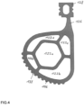
- the sealing section 120 has a plurality of tubular first hollow chambers 122a to 122e running parallel to the lower edge 118 of the door leaf 104 .
- These hollow chambers 122a to 122e are in particular arranged parallel to one another.
- a central hollow chamber 122a is preferably provided, which is surrounded in the manner of a satellite by further hollow chambers 122b to 122e, viewed in the circumferential direction.
- FIG 5 12 is a cross-sectional view of a pivoting/sliding door assembly 108 according to another embodiment having a lower door seal 116 according to FIG 2 and 3 , wherein the door leaf 104 and the sliding step 142 are in the extended position.
- the sealing section 120 has, at least in the region of the contact surface 138, an outwardly projecting first toothing 156 running transversely to the movement of the door leaf 104, which in the course of the closing process engages with a second toothing 158 running transversely to the movement of the door leaf 104 on the tread 114 engages.
- the first toothing 156 in turn disengages from the second toothing 158 .
- the engagement and disengagement is enabled by the elastic properties of the sealing portion 120 .
- the lower door seal 116 can be designed in one piece with, for example, two side door seals fastened to the door leaf 104, for example by the meter, and continuously transition into these side door seals in, for example, curved sections.
- the lower door seal 116 can also be attached to the lower edge 118 or in the area of the lower edge 118 of the door leaf 104 by an adjustment device (not shown here) in such a way that a vertical position of the lower door seal 166 in relation to the lower edge 118 of the door leaf 104 can be adjusted.
Landscapes
- Engineering & Computer Science (AREA)
- Mechanical Engineering (AREA)
- Specific Sealing Or Ventilating Devices For Doors And Windows (AREA)
Claims (22)
- Système (108) de porte louvoyante - coulissante à monter dans une ouverture de porte d'un véhicule (100), comprenanta) un encadrement (102) de porte,b) au moins une porte louvoyante - coulissante, qui a un battant (104) de porte, lequel est mobile par rapport à l'encadrement de la porte et est monté sur l'encadrement (102) de porte entre une position de fermeture du battant de la porte et une position d'ouverture du battant de la porte, de manière à ce que la direction de déplacement du battant (104) de la porte, pendant une opération d'ouverture et pendant une opération de fermeture, s'étende sensiblement à l'horizontale,c) un seuil (112) de porte de l'encadrement (102) de la porte ayant un marchepied (114) incliné sur l'horizontale pour des personnes qui montent et qui descendent,d) un système (106) d'étanchéité de porte ayant une étanchéité (116) de porte inférieure passive, qui rend étanche un intervalle entre un bord (118) inférieure du battant (104) de la porte et le marchepied (114), dans lequele) l'étanchéité (116) inférieure de la porte est fixée au bord (118) inférieur ou dans la partie du bord (118) inférieur du battant (104) de la porte et dans la position de fermeture du battant de la porte vient, par une partie (120) d'étanchéité, en étanchéité sur le marchepied (114) incliné, caractérisé en ce quef) l'étanchéité (120) de porte a au moins une première chambre (122 ; 122a-122e) creuse s'étendant, en forme de boudin, parallèlement au bord (118) inférieur du battant (104) de la porte et ayant, dans la position d'ouverture du battant de la porte, une première section transversale non déformée et dans la position de fermeture du battant de la porte, une deuxième section transversale déformée par rapport à la première section transversale, et en ce queg) il est prévu, à la porte louvoyante - coulissante, un seul battant (104) de la porte ou deux battants de la porte, dans lequel les deux battants de la porte s'appliquent l'un à l'autre pour la fermeture de l'ouverture de porte et s'éloignent l'un de l'autre pour dégager l'ouverture de porte.
- Système de porte louvoyante - coulissante suivant la revendication 1, caractérisé en ce que le déplacement (132) du battant (104) de la porte pendant l'opération de fermeture, l'inclinaison du marchepied (114) sur l'horizontale et la partie (120) d'étanchéité sont réalisés et adaptés les uns aux autres, de manière à ce que, à partir de la position d'ouverture du battant de la porte, dans laquelle il y a la première section transversale non déformée de la au moins une première chambre (122 ; 122a-122e) creuse, à la fin d'une première partie de l'opération de fermeture du battant (104) de la porte, la partie (120) d'étanchéité s'applique au marchepied (114) par une surface (138) de contact, et en ce que, pendant une deuxième partie de l'opération de fermeture, se raccordant dans le temps à la première partie, la partie (120) d'étanchéité reste sensiblement adhérente par sa surface (138) de contact au marchepied (114) et le battant (104) de la porte continue à se déplacer dans la direction de la position de fermeture et, lorsqu'à la fin de la deuxième partie de l'opération de fermeture, la position de fermeture du battant de la porte est atteinte finalement par le battant (104) de la porte, la au moins une première chambre (122 ; 122a-122e) creuse prend alors la deuxième section transversale déformée.
- Système de porte louvoyante - coulissante suivant la revendication 2, caractérisé en ce que la partie (120) d'étanchéité a, au moins dans la région de la surface (138) de contact, une première denture (156) en saillie vers l'extérieur, qui s'étend transversalement au déplacement du battant (104) de la porte et qui, au cours de l'opération de fermeture, vient en prise avec une deuxième denture (158), s'étendant transversalement au déplacement du battant (104) de la porte, sur le marchepied (114) et vient hors de prise au cours de l'opération d'ouverture.
- Système de porte louvoyante - coulissante suivant l'une des revendications précédentes, caractérisé en ce que l'étanchéité (116) inférieure de porte a une partie (126) d'entretoise, se raccordant à la partie (120) d'étanchéité, en particulier en matériau plein, qui se transforme en une partie (128) de maintien, qui est fixée, en particulier de manière amovible, au bord (118) inférieur du battant (104) de la porte.
- Système de porte louvoyante - coulissante suivant la revendication 4, caractérisé en ce que, sur le bord (118) inférieur du battant (104) de la porte, est monté un dispositif (130) d'appui, de manière à ce qu'au moins la partie (126) d'entretoise s'appuie, pendant l'opération de fermeture, dans un sens contraire par rapport au sens (132) de déplacement du battant (104) de la porte.
- Système de porte louvoyante - coulissante suivant la revendication 4 ou 5, caractérisé en ce que la partie (120) d'étanchéité, la partie (126) d'entretoise et la partie (128) de maintien sont constituées d'une seule pièce en un matériau élastomère.
- Système de porte louvoyante - coulissante suivant la revendication 6, caractérisé en ce que la partie (128) de maintien est reçue à complémentarité de forme dans un évidement (134) de type en rainure du bord (118) inférieur du battant (104) de la porte, dans lequel l'évidement (134) de type en rainure a une section transversale à contredépouille, dans laquelle la partie (128) de maintien pénètre à complémentarité de forme.
- Système de porte louvoyante - coulissante suivant l'une des revendications 4 à 7, caractérisé en ce que la partie (128) de maintien a au moins une deuxième chambre (136) creuse de type en boudin.
- Système de porte louvoyante - coulissante suivant l'une des revendications précédentes, caractérisé en ce que le marchepied (114) du seuil (112) de porte fait, par rapport à l'horizontale, un premier angle (α) dans une plage de 10 degrés à 15 degrés.
- Système de porte louvoyante - coulissante suivant l'une des revendications précédentes, caractérisé en ce qu'il a un dispositif (140) de marchepied pour faire un pont sur un intervalle entre le seuil (112) de porte et une partie pouvant être empruntée et extérieure par rapport au véhicule (100), dispositif qui comprend un marchepied (142) pouvant être entraîné entre une position initiale escamotée du marchepied et une position finale déployée, dans lequel le marchepied (142) est monté de manière à pouvoir être escamoté et déployé en-dessous du seuil (112) de porte.
- Système de porte louvoyante - coulissante suivant la revendication 10, caractérisé en ce qu'il a un dispositif (144) de balayage, qui a un volet (146) pivotant autour d'un axe horizontal à une extrémité libre du marchepied (114), volet, qui est constitué et prévu pour balayer de la saleté et former une rampe sur le marchepied (142) dans la position initiale du marchepied, dans la position finale du marchepied, tout comme dans des positions intermédiaires du marchepied entre la position initiale du marchepied et la position finale du marchepied.
- Système de porte louvoyante - coulissante suivant la revendication 11, caractérisé en ce que le volet (146) est constitué pour rendre étanche un intervalle entre une surface (150) inférieure, en position d'utilisation, du seuil (112) de porte et une surface (152) supérieure, en position d'utilisation, du marchepied (142).
- Système de porte louvoyante - coulissante suivant la revendication 12, caractérisé en ce que le volet (146) fait, avec la surface (152) supérieure du marchepied (142), un deuxième angle (β) dans une plage de 20 degrés à 40 degrés.
- Système de porte louvoyante - coulissante suivant l'une des revendications 11 à 13, caractérisé en ce qu'une liaison (154) articulée est prévue entre le volet (146) et l'extrémité libre du seuil (112) de porte.
- Système de porte louvoyante - coulissante suivant l'une des revendications 11 à 14, caractérisé en ce que, dans la position de fermeture du battant de la porte, le volet (146) est en saillie sous la partie (120) d'étanchéité de l'étanchéité (116) inférieure de la porte et n'est pas en contact avec la partie (120) d'étanchéité.
- Système de porte louvoyante - coulissante suivant l'une des revendications précédentes, caractérisé en ce que l'étanchéité (116) inférieure de la porte forme une partie inférieure d'une étanchéité de porte faisant le tour du dispositif (106) d'étanchéité de porte, lequel est disposé en faisant le tour sur le pourtour du battant (104) de la porte.
- Système de porte louvoyante - coulissante suivant l'une des revendications précédentes, caractérisé en ce que la partie (120) d'étanchéité a plusieurs premières chambres (122a-122e) creuses en forme de boudin s'étendant parallèlement au bord (118) inférieur du battant (104) de la porte et disposées notamment en étant parallèles entre elles.
- Système de porte louvoyante - coulissante suivant la revendication 17, caractérisé en ce qu'il est prévu une chambre (122a) creuse centrale, qui est entourée, et considéré dans la direction du pourtour, d'autres chambres (122b-122e) creuses.
- Système de porte louvoyante - coulissante suivant l'une des revendications précédentes, caractérisé en ce que l'étanchéité (116) inférieure de la porte est réalisée en une seule pièce avec au moins une étanchéité latérale de la porte et se transforme d'une manière continue en celle-ci en une partie incurvée.
- Système de porte louvoyante - coulissante suivant l'une des revendications précédentes, caractérisé en ce que l'étanchéité (116) inférieure de la porte est fixée au bord (118) inférieure ou dans la partie du bord (118) inférieur du battant (104) de la porte par un dispositif de réglage, de manière à pouvoir régler une position verticale de l'étanchéité (166) inférieure de la porte par rapport au bord (118) inférieur du battant (104) de la porte.
- Système de porte louvoyante - coulissante suivant l'une des revendications précédentes, caractérisé en ce que l'étanchéité (116) inférieure de la porte est fixée au bord (118) inférieure ou dans la partie du bord (118) inférieur du battant (104) de la porte, de manière à fixer une position verticale de l'étanchéité (166) inférieure de la porte par rapport au bord (118) inférieur du battant (104) de la porte.
- Véhicule (100) ferroviaire ayant au moins un système (108) de porte louvoyante - coulissante suivant l'une des revendications précédentes.
Applications Claiming Priority (2)
| Application Number | Priority Date | Filing Date | Title |
|---|---|---|---|
| DE102018008139.8A DE102018008139B4 (de) | 2018-10-15 | 2018-10-15 | Schwenkschiebetürvorrichtung zur Anordnung in einer Türöffnung eines Fahrzeugs |
| PCT/EP2019/074973 WO2020078650A1 (fr) | 2018-10-15 | 2019-09-18 | Système de porte louvoyante-coulissante destiné à être agencé dans une ouverture de porte d'un encadrement de porte d'un véhicule |
Publications (2)
| Publication Number | Publication Date |
|---|---|
| EP3867122A1 EP3867122A1 (fr) | 2021-08-25 |
| EP3867122B1 true EP3867122B1 (fr) | 2023-07-19 |
Family
ID=68062911
Family Applications (1)
| Application Number | Title | Priority Date | Filing Date |
|---|---|---|---|
| EP19773770.3A Active EP3867122B1 (fr) | 2018-10-15 | 2019-09-18 | Système de porte louvoyante-coulissante destiné à être agencé dans une ouverture de porte d'un encadrement de porte d'un véhicule |
Country Status (7)
| Country | Link |
|---|---|
| US (1) | US20210380147A1 (fr) |
| EP (1) | EP3867122B1 (fr) |
| CN (1) | CN112867654A (fr) |
| DE (1) | DE102018008139B4 (fr) |
| ES (1) | ES2960594T3 (fr) |
| PL (1) | PL3867122T3 (fr) |
| WO (1) | WO2020078650A1 (fr) |
Families Citing this family (2)
| Publication number | Priority date | Publication date | Assignee | Title |
|---|---|---|---|---|
| JP7279651B2 (ja) * | 2020-01-22 | 2023-05-23 | トヨタ自動車株式会社 | 車両用ドアのシール構造 |
| DE102022118452A1 (de) * | 2021-08-04 | 2023-02-09 | Bode - Die Tür Gmbh | Türsystem für ein Fahrzeug des öffentlichen Personenverkehrs |
Family Cites Families (16)
| Publication number | Priority date | Publication date | Assignee | Title |
|---|---|---|---|---|
| US3226780A (en) * | 1964-07-06 | 1966-01-04 | Robert L Landis | Sealing means |
| AU497070B2 (en) | 1974-03-21 | 1978-11-23 | Westinghouse Brake And Signal Compan'i Limited | Vehicle door arrangements |
| DE3710451A1 (de) | 1987-03-30 | 1988-10-20 | Kiekert Gmbh Co Kg | Teleskopschwenkschiebetuer fuer schienenfahrzeuge |
| AT406361B (de) * | 1997-09-10 | 2000-04-25 | Ife Gmbh | Zweiflügelige druckertüchtige türe für ein schienenfahrzeug |
| DE20311653U1 (de) * | 2003-07-29 | 2003-10-02 | Gebr. Bode GmbH & Co. KG, 34123 Kassel | Dichtungseinrichtung an einer Schwenkschiebetür für Fahrzeuge zur Personenbeförderung, insbesondere Schienenfahrzeuge |
| EP1643071A1 (fr) * | 2004-09-29 | 2006-04-05 | Cardo Door Ab | Porte en sections comprenant un profil de joint entre les sections et un procédé de fabrication d'une porte en section |
| DE202008002914U1 (de) | 2008-02-29 | 2009-07-09 | Gebr. Bode GmbH & Co. KG Fahrzeugtürsysteme | Dichtungsvorrichtung |
| US20120260579A1 (en) | 2011-04-15 | 2012-10-18 | Ultrafab, Inc. | Multiple Hollow Bulb Seal |
| DE102014208288A1 (de) | 2014-05-02 | 2015-11-05 | Siemens Aktiengesellschaft | Druckertüchtigte Tür für ein Schienenfahrzeug des Hochgeschwindigkeitsverkehrs |
| DE202014104110U1 (de) | 2014-09-02 | 2014-09-16 | Knorr-Bremse Gmbh | Türdichtungsvorrichtung, Türdichtungssystem und Türflügel für ein Schienenfahrzeug |
| EP3245375B1 (fr) * | 2015-01-15 | 2021-05-19 | ASSA ABLOY (Schweiz) AG | Joint pour une porte sans seuil |
| DE102016112862A1 (de) * | 2016-07-13 | 2018-01-18 | Bombardier Transportation Gmbh | Türvorrichtung und Montageverfahren dafür |
| DE102016013797A1 (de) * | 2016-11-21 | 2018-05-24 | Knorr-Bremse Gesellschaft Mit Beschränkter Haftung | Türmodul zur Anordnung in einer Türöffnung eines Wagenkastens eines Fahrzeugs |
| CN206503509U (zh) * | 2017-02-17 | 2017-09-19 | 扬州碧源人防工程有限公司 | 一种便于车辆通行的防爆门 |
| DE102017002018A1 (de) * | 2017-03-03 | 2018-09-06 | Knorr-Bremse Gesellschaft Mit Beschränkter Haftung | Schiebetrittanordnung für ein Kraftfahrzeug oder für ein Schienenfahrzeug |
| CN108099561A (zh) * | 2018-01-24 | 2018-06-01 | 扬州华通橡塑有限公司 | 一种塞拉门密封条接角及加工方法 |
-
2018
- 2018-10-15 DE DE102018008139.8A patent/DE102018008139B4/de active Active
-
2019
- 2019-09-18 CN CN201980067944.1A patent/CN112867654A/zh active Pending
- 2019-09-18 EP EP19773770.3A patent/EP3867122B1/fr active Active
- 2019-09-18 PL PL19773770.3T patent/PL3867122T3/pl unknown
- 2019-09-18 US US17/285,837 patent/US20210380147A1/en active Pending
- 2019-09-18 ES ES19773770T patent/ES2960594T3/es active Active
- 2019-09-18 WO PCT/EP2019/074973 patent/WO2020078650A1/fr unknown
Also Published As
| Publication number | Publication date |
|---|---|
| ES2960594T3 (es) | 2024-03-05 |
| CN112867654A (zh) | 2021-05-28 |
| US20210380147A1 (en) | 2021-12-09 |
| EP3867122A1 (fr) | 2021-08-25 |
| DE102018008139B4 (de) | 2022-01-05 |
| DE102018008139A1 (de) | 2020-04-16 |
| PL3867122T3 (pl) | 2024-01-29 |
| WO2020078650A1 (fr) | 2020-04-23 |
Similar Documents
| Publication | Publication Date | Title |
|---|---|---|
| EP3102473B1 (fr) | Porte à l'épreuve de la pression pour véhicule ferroviaire circulant à grande vitesse | |
| EP3589524B1 (fr) | Ensemble marchepied coulissante pour véhicule automobile ou pour véhicule ferroviaire | |
| EP3867122B1 (fr) | Système de porte louvoyante-coulissante destiné à être agencé dans une ouverture de porte d'un encadrement de porte d'un véhicule | |
| EP3541678B1 (fr) | Module de porte à monter dans une ouverture de porte d'une caisse de véhicule | |
| EP3121086A1 (fr) | Vehicule ferroviaire, comprenant un element de pont destine a former un pont entre une porte et un quai | |
| DE202018106885U1 (de) | Trittsystem für ein Fahrzeug | |
| DE4242624C2 (de) | Karosserieteil für ein Kraftfahrzeug | |
| EP3213973A1 (fr) | Dispositif pour monter dans un vehicule | |
| EP3810479B1 (fr) | Comble-lacune pour véhicule ferroviaire | |
| DE102016201275B3 (de) | Frontnotausstieg | |
| EP2060729A2 (fr) | Système d'étanchéité d'angle pour vantail de fenêtre ou porte | |
| DE102014013772B4 (de) | Fahrzeug mit einer Fahrzeugtür | |
| EP4147893A1 (fr) | Porte coulissante pivotante à joint pliant d'étanchéité de porte et véhicule | |
| EP0931532A1 (fr) | Rampe pour véhicules | |
| EP3812234B1 (fr) | Passerelle pour un véhicule de transport de personnes et véhicule de transport de personnes | |
| EP1857085A2 (fr) | Rampe d'accès démontable pour véhicules de transport en commun régionaux et longue distance | |
| AT505101A2 (de) | Türführung und türbefestigungssystem für passagier-schienen-fahrzeuge | |
| DE102017206495A1 (de) | Vorrichtung und Verfahren zur Herstellung eines niveaugleichen Einstiegs für unterschiedliche Bahnsteighöhen | |
| DE3536621C1 (de) | Einweispuffer für schwenkbare Türen, Hauben, Klappen oder dergleichen von Kraftwagen | |
| EP3303033B1 (fr) | Dispositif d'occulation pour une vitre ou une région de toit vitré d'un habitacle de véhicule | |
| DE3401390A1 (de) | Schiebetuere fuer fahrzeuge od. dgl. | |
| WO2018215392A1 (fr) | Cabine d'ascenseur conçue pour un système d'ascenseur, et procédé pour ouvrir et fermer un jour de porte | |
| DE102018104194A1 (de) | Horizontalrahmenteil für einen Schiebetür- und/oder Schiebefensterrahmen, Schiebetür- und/oder Schiebefensterrahmen sowie Schiebetür- und/oder Schiebefenstersystem | |
| DE202018103171U1 (de) | Passive Dichtung für eine Schiebetür | |
| DE102016125784B4 (de) | Schiebetritt für ein Schienenfahrzeug |
Legal Events
| Date | Code | Title | Description |
|---|---|---|---|
| STAA | Information on the status of an ep patent application or granted ep patent |
Free format text: STATUS: UNKNOWN |
|
| STAA | Information on the status of an ep patent application or granted ep patent |
Free format text: STATUS: THE INTERNATIONAL PUBLICATION HAS BEEN MADE |
|
| PUAI | Public reference made under article 153(3) epc to a published international application that has entered the european phase |
Free format text: ORIGINAL CODE: 0009012 |
|
| STAA | Information on the status of an ep patent application or granted ep patent |
Free format text: STATUS: REQUEST FOR EXAMINATION WAS MADE |
|
| 17P | Request for examination filed |
Effective date: 20210517 |
|
| AK | Designated contracting states |
Kind code of ref document: A1 Designated state(s): AL AT BE BG CH CY CZ DE DK EE ES FI FR GB GR HR HU IE IS IT LI LT LU LV MC MK MT NL NO PL PT RO RS SE SI SK SM TR |
|
| DAV | Request for validation of the european patent (deleted) | ||
| DAX | Request for extension of the european patent (deleted) | ||
| REG | Reference to a national code |
Ref country code: DE Ref legal event code: R079 Ref document number: 502019008603 Country of ref document: DE Free format text: PREVIOUS MAIN CLASS: B61D0019000000 Ipc: B61D0019020000 Ref country code: DE Ref legal event code: R079 Free format text: PREVIOUS MAIN CLASS: B61D0019000000 Ipc: B61D0019020000 |
|
| GRAP | Despatch of communication of intention to grant a patent |
Free format text: ORIGINAL CODE: EPIDOSNIGR1 |
|
| STAA | Information on the status of an ep patent application or granted ep patent |
Free format text: STATUS: GRANT OF PATENT IS INTENDED |
|
| RIC1 | Information provided on ipc code assigned before grant |
Ipc: B60J 10/86 20160101ALI20230224BHEP Ipc: B60J 10/248 20160101ALI20230224BHEP Ipc: B60J 10/24 20160101ALI20230224BHEP Ipc: B61D 19/00 20060101ALI20230224BHEP Ipc: B61D 19/02 20060101AFI20230224BHEP |
|
| INTG | Intention to grant announced |
Effective date: 20230317 |
|
| GRAS | Grant fee paid |
Free format text: ORIGINAL CODE: EPIDOSNIGR3 |
|
| GRAA | (expected) grant |
Free format text: ORIGINAL CODE: 0009210 |
|
| STAA | Information on the status of an ep patent application or granted ep patent |
Free format text: STATUS: THE PATENT HAS BEEN GRANTED |
|
| AK | Designated contracting states |
Kind code of ref document: B1 Designated state(s): AL AT BE BG CH CY CZ DE DK EE ES FI FR GB GR HR HU IE IS IT LI LT LU LV MC MK MT NL NO PL PT RO RS SE SI SK SM TR |
|
| REG | Reference to a national code |
Ref country code: GB Ref legal event code: FG4D Free format text: NOT ENGLISH |
|
| REG | Reference to a national code |
Ref country code: CH Ref legal event code: EP |
|
| REG | Reference to a national code |
Ref country code: DE Ref legal event code: R096 Ref document number: 502019008603 Country of ref document: DE |
|
| REG | Reference to a national code |
Ref country code: IE Ref legal event code: FG4D Free format text: LANGUAGE OF EP DOCUMENT: GERMAN |
|
| PGFP | Annual fee paid to national office [announced via postgrant information from national office to epo] |
Ref country code: GB Payment date: 20230921 Year of fee payment: 5 |
|
| REG | Reference to a national code |
Ref country code: LT Ref legal event code: MG9D |
|
| REG | Reference to a national code |
Ref country code: NL Ref legal event code: MP Effective date: 20230719 |
|
| PGFP | Annual fee paid to national office [announced via postgrant information from national office to epo] |
Ref country code: FR Payment date: 20230918 Year of fee payment: 5 Ref country code: DE Payment date: 20230919 Year of fee payment: 5 |
|
| PG25 | Lapsed in a contracting state [announced via postgrant information from national office to epo] |
Ref country code: NL Free format text: LAPSE BECAUSE OF FAILURE TO SUBMIT A TRANSLATION OF THE DESCRIPTION OR TO PAY THE FEE WITHIN THE PRESCRIBED TIME-LIMIT Effective date: 20230719 |
|
| PG25 | Lapsed in a contracting state [announced via postgrant information from national office to epo] |
Ref country code: GR Free format text: LAPSE BECAUSE OF FAILURE TO SUBMIT A TRANSLATION OF THE DESCRIPTION OR TO PAY THE FEE WITHIN THE PRESCRIBED TIME-LIMIT Effective date: 20231020 |
|
| PGFP | Annual fee paid to national office [announced via postgrant information from national office to epo] |
Ref country code: ES Payment date: 20231019 Year of fee payment: 5 |
|
| PG25 | Lapsed in a contracting state [announced via postgrant information from national office to epo] |
Ref country code: IS Free format text: LAPSE BECAUSE OF FAILURE TO SUBMIT A TRANSLATION OF THE DESCRIPTION OR TO PAY THE FEE WITHIN THE PRESCRIBED TIME-LIMIT Effective date: 20231119 |
|
| PG25 | Lapsed in a contracting state [announced via postgrant information from national office to epo] |
Ref country code: SE Free format text: LAPSE BECAUSE OF FAILURE TO SUBMIT A TRANSLATION OF THE DESCRIPTION OR TO PAY THE FEE WITHIN THE PRESCRIBED TIME-LIMIT Effective date: 20230719 Ref country code: RS Free format text: LAPSE BECAUSE OF FAILURE TO SUBMIT A TRANSLATION OF THE DESCRIPTION OR TO PAY THE FEE WITHIN THE PRESCRIBED TIME-LIMIT Effective date: 20230719 Ref country code: PT Free format text: LAPSE BECAUSE OF FAILURE TO SUBMIT A TRANSLATION OF THE DESCRIPTION OR TO PAY THE FEE WITHIN THE PRESCRIBED TIME-LIMIT Effective date: 20231120 Ref country code: NO Free format text: LAPSE BECAUSE OF FAILURE TO SUBMIT A TRANSLATION OF THE DESCRIPTION OR TO PAY THE FEE WITHIN THE PRESCRIBED TIME-LIMIT Effective date: 20231019 Ref country code: LV Free format text: LAPSE BECAUSE OF FAILURE TO SUBMIT A TRANSLATION OF THE DESCRIPTION OR TO PAY THE FEE WITHIN THE PRESCRIBED TIME-LIMIT Effective date: 20230719 Ref country code: LT Free format text: LAPSE BECAUSE OF FAILURE TO SUBMIT A TRANSLATION OF THE DESCRIPTION OR TO PAY THE FEE WITHIN THE PRESCRIBED TIME-LIMIT Effective date: 20230719 Ref country code: IS Free format text: LAPSE BECAUSE OF FAILURE TO SUBMIT A TRANSLATION OF THE DESCRIPTION OR TO PAY THE FEE WITHIN THE PRESCRIBED TIME-LIMIT Effective date: 20231119 Ref country code: HR Free format text: LAPSE BECAUSE OF FAILURE TO SUBMIT A TRANSLATION OF THE DESCRIPTION OR TO PAY THE FEE WITHIN THE PRESCRIBED TIME-LIMIT Effective date: 20230719 Ref country code: GR Free format text: LAPSE BECAUSE OF FAILURE TO SUBMIT A TRANSLATION OF THE DESCRIPTION OR TO PAY THE FEE WITHIN THE PRESCRIBED TIME-LIMIT Effective date: 20231020 Ref country code: FI Free format text: LAPSE BECAUSE OF FAILURE TO SUBMIT A TRANSLATION OF THE DESCRIPTION OR TO PAY THE FEE WITHIN THE PRESCRIBED TIME-LIMIT Effective date: 20230719 |
|
| PGFP | Annual fee paid to national office [announced via postgrant information from national office to epo] |
Ref country code: CZ Payment date: 20230907 Year of fee payment: 5 |
|
| P01 | Opt-out of the competence of the unified patent court (upc) registered |
Effective date: 20240123 |
|
| REG | Reference to a national code |
Ref country code: ES Ref legal event code: FG2A Ref document number: 2960594 Country of ref document: ES Kind code of ref document: T3 Effective date: 20240305 |
|
| REG | Reference to a national code |
Ref country code: DE Ref legal event code: R097 Ref document number: 502019008603 Country of ref document: DE |
|
| PG25 | Lapsed in a contracting state [announced via postgrant information from national office to epo] |
Ref country code: SM Free format text: LAPSE BECAUSE OF FAILURE TO SUBMIT A TRANSLATION OF THE DESCRIPTION OR TO PAY THE FEE WITHIN THE PRESCRIBED TIME-LIMIT Effective date: 20230719 Ref country code: RO Free format text: LAPSE BECAUSE OF FAILURE TO SUBMIT A TRANSLATION OF THE DESCRIPTION OR TO PAY THE FEE WITHIN THE PRESCRIBED TIME-LIMIT Effective date: 20230719 Ref country code: EE Free format text: LAPSE BECAUSE OF FAILURE TO SUBMIT A TRANSLATION OF THE DESCRIPTION OR TO PAY THE FEE WITHIN THE PRESCRIBED TIME-LIMIT Effective date: 20230719 Ref country code: DK Free format text: LAPSE BECAUSE OF FAILURE TO SUBMIT A TRANSLATION OF THE DESCRIPTION OR TO PAY THE FEE WITHIN THE PRESCRIBED TIME-LIMIT Effective date: 20230719 Ref country code: SK Free format text: LAPSE BECAUSE OF FAILURE TO SUBMIT A TRANSLATION OF THE DESCRIPTION OR TO PAY THE FEE WITHIN THE PRESCRIBED TIME-LIMIT Effective date: 20230719 |
|
| REG | Reference to a national code |
Ref country code: CH Ref legal event code: PL |
|
| PG25 | Lapsed in a contracting state [announced via postgrant information from national office to epo] |
Ref country code: LU Free format text: LAPSE BECAUSE OF NON-PAYMENT OF DUE FEES Effective date: 20230918 |
|
| PLBE | No opposition filed within time limit |
Free format text: ORIGINAL CODE: 0009261 |
|
| STAA | Information on the status of an ep patent application or granted ep patent |
Free format text: STATUS: NO OPPOSITION FILED WITHIN TIME LIMIT |
|
| REG | Reference to a national code |
Ref country code: BE Ref legal event code: MM Effective date: 20230930 |
|
| PG25 | Lapsed in a contracting state [announced via postgrant information from national office to epo] |
Ref country code: LU Free format text: LAPSE BECAUSE OF NON-PAYMENT OF DUE FEES Effective date: 20230918 Ref country code: IT Free format text: LAPSE BECAUSE OF FAILURE TO SUBMIT A TRANSLATION OF THE DESCRIPTION OR TO PAY THE FEE WITHIN THE PRESCRIBED TIME-LIMIT Effective date: 20230719 Ref country code: MC Free format text: LAPSE BECAUSE OF FAILURE TO SUBMIT A TRANSLATION OF THE DESCRIPTION OR TO PAY THE FEE WITHIN THE PRESCRIBED TIME-LIMIT Effective date: 20230719 |
|
| PGFP | Annual fee paid to national office [announced via postgrant information from national office to epo] |
Ref country code: PL Payment date: 20230906 Year of fee payment: 5 |
|
| 26N | No opposition filed |
Effective date: 20240422 |
|
| REG | Reference to a national code |
Ref country code: IE Ref legal event code: MM4A |
|
| PG25 | Lapsed in a contracting state [announced via postgrant information from national office to epo] |
Ref country code: IE Free format text: LAPSE BECAUSE OF NON-PAYMENT OF DUE FEES Effective date: 20230918 |
|
| PG25 | Lapsed in a contracting state [announced via postgrant information from national office to epo] |
Ref country code: CH Free format text: LAPSE BECAUSE OF NON-PAYMENT OF DUE FEES Effective date: 20230930 |
|
| PG25 | Lapsed in a contracting state [announced via postgrant information from national office to epo] |
Ref country code: IE Free format text: LAPSE BECAUSE OF NON-PAYMENT OF DUE FEES Effective date: 20230918 Ref country code: CH Free format text: LAPSE BECAUSE OF NON-PAYMENT OF DUE FEES Effective date: 20230930 Ref country code: SI Free format text: LAPSE BECAUSE OF FAILURE TO SUBMIT A TRANSLATION OF THE DESCRIPTION OR TO PAY THE FEE WITHIN THE PRESCRIBED TIME-LIMIT Effective date: 20230719 |
|
| PG25 | Lapsed in a contracting state [announced via postgrant information from national office to epo] |
Ref country code: BE Free format text: LAPSE BECAUSE OF NON-PAYMENT OF DUE FEES Effective date: 20230930 |