EP3867122B1 - Pivoting and sliding door device for arrangement in a door opening of a door frame of a vehicle - Google Patents
Pivoting and sliding door device for arrangement in a door opening of a door frame of a vehicle Download PDFInfo
- Publication number
- EP3867122B1 EP3867122B1 EP19773770.3A EP19773770A EP3867122B1 EP 3867122 B1 EP3867122 B1 EP 3867122B1 EP 19773770 A EP19773770 A EP 19773770A EP 3867122 B1 EP3867122 B1 EP 3867122B1
- Authority
- EP
- European Patent Office
- Prior art keywords
- door
- section
- door leaf
- sliding
- sliding plug
- Prior art date
- Legal status (The legal status is an assumption and is not a legal conclusion. Google has not performed a legal analysis and makes no representation as to the accuracy of the status listed.)
- Active
Links
- 238000007789 sealing Methods 0.000 claims description 96
- 238000000034 method Methods 0.000 claims description 33
- 230000002093 peripheral effect Effects 0.000 claims description 5
- 229920001971 elastomer Polymers 0.000 claims description 4
- 239000000806 elastomer Substances 0.000 claims description 4
- 238000007790 scraping Methods 0.000 claims description 3
- 239000011343 solid material Substances 0.000 claims description 3
- 239000000463 material Substances 0.000 claims description 2
- 238000011161 development Methods 0.000 description 7
- 230000018109 developmental process Effects 0.000 description 7
- 230000000694 effects Effects 0.000 description 7
- 230000007704 transition Effects 0.000 description 4
- 230000001419 dependent effect Effects 0.000 description 2
- 230000005489 elastic deformation Effects 0.000 description 2
- 239000006260 foam Substances 0.000 description 2
- 241001295925 Gegenes Species 0.000 description 1
- 239000012459 cleaning agent Substances 0.000 description 1
- 230000006835 compression Effects 0.000 description 1
- 238000007906 compression Methods 0.000 description 1
- 239000013013 elastic material Substances 0.000 description 1
- 239000013536 elastomeric material Substances 0.000 description 1
- 238000001125 extrusion Methods 0.000 description 1
- 238000002347 injection Methods 0.000 description 1
- 239000007924 injection Substances 0.000 description 1
- 230000003137 locomotive effect Effects 0.000 description 1
- 230000008092 positive effect Effects 0.000 description 1
- 238000009423 ventilation Methods 0.000 description 1
Images


Classifications
-
- B—PERFORMING OPERATIONS; TRANSPORTING
- B61—RAILWAYS
- B61D—BODY DETAILS OR KINDS OF RAILWAY VEHICLES
- B61D19/00—Door arrangements specially adapted for rail vehicles
- B61D19/003—Door arrangements specially adapted for rail vehicles characterised by the movements of the door
- B61D19/008—Door arrangements specially adapted for rail vehicles characterised by the movements of the door both swinging and sliding
-
- B—PERFORMING OPERATIONS; TRANSPORTING
- B60—VEHICLES IN GENERAL
- B60J—WINDOWS, WINDSCREENS, NON-FIXED ROOFS, DOORS, OR SIMILAR DEVICES FOR VEHICLES; REMOVABLE EXTERNAL PROTECTIVE COVERINGS SPECIALLY ADAPTED FOR VEHICLES
- B60J10/00—Sealing arrangements
- B60J10/20—Sealing arrangements characterised by the shape
- B60J10/24—Sealing arrangements characterised by the shape having tubular parts
- B60J10/248—Sealing arrangements characterised by the shape having tubular parts having two or more tubular cavities, e.g. formed by partition walls
-
- B—PERFORMING OPERATIONS; TRANSPORTING
- B60—VEHICLES IN GENERAL
- B60J—WINDOWS, WINDSCREENS, NON-FIXED ROOFS, DOORS, OR SIMILAR DEVICES FOR VEHICLES; REMOVABLE EXTERNAL PROTECTIVE COVERINGS SPECIALLY ADAPTED FOR VEHICLES
- B60J10/00—Sealing arrangements
- B60J10/80—Sealing arrangements specially adapted for opening panels, e.g. doors
- B60J10/86—Sealing arrangements specially adapted for opening panels, e.g. doors arranged on the opening panel
-
- B—PERFORMING OPERATIONS; TRANSPORTING
- B61—RAILWAYS
- B61D—BODY DETAILS OR KINDS OF RAILWAY VEHICLES
- B61D19/00—Door arrangements specially adapted for rail vehicles
- B61D19/02—Door arrangements specially adapted for rail vehicles for carriages
Definitions
- the invention is based on a pivoting sliding door device for arrangement in a door opening of a vehicle, in particular a rail vehicle, according to the preamble of claim 1.
- the invention also relates to a rail vehicle with at least one such pivoting sliding door device according to claim 22.
- pivoting sliding doors Vehicles for mass transportation of people often have pivoting sliding doors or folding doors through which passengers can enter and exit the vehicle.
- the at least one door leaf opens and closes through a combination of a first direction of movement and a second direction of movement, the first direction of movement being perpendicular to an outer surface of the vehicle and the second direction of movement being parallel to the outer surface of the vehicle.
- the door opening can be released in a space-saving manner and people waiting on or in the vehicle are not impeded by the door leaf swinging out.
- the use of pivoting sliding doors therefore ensures that the passengers can get on and off quickly.
- a further requirement of such pivoting and sliding door devices is to seal off the interior of the vehicle from the outside with the aid of a door sealing device.
- a generic pivoting sliding door device or a generic rail vehicle are from EP 3 269 613 A1 known.
- the lower door seal is designed as an elastomer body with two sealing lips, which is resiliently mounted on a support frame by a spring element.
- the support frame is in turn vertically adjustable relative to the bottom edge of the door leaf by adjustment fasteners.
- the disadvantage of such a design is, on the one hand, the high structural complexity and, on the other hand, the relatively low sealing effect of the two sealing lips.
- DE 20 2008 002 914 U1 discloses a sealing device for a vehicle door, with a portal having an inside and an outside, and a door panel having an inside and an outside, wherein a gap forms between the portal and the door panel in the closed state of the door panel and the outside of the door leaf has a projection which extends across the gap in the direction of the portal, wherein within the gap at the portal a counter bearing is arranged and between the counter bearing and the projection there is an elastic sealing element that is compressed in the closed state of the vehicle door.
- the sealing device since the counter bearing protrudes vertically, the sealing device is not suitable for sealing against a walking surface.
- the present invention is based on the object of further developing a pivoting sliding door device of the type mentioned at the outset in such a way that a high sealing effect is achieved with respect to a tread surface with a simple design of the door sealing device. Furthermore, a rail vehicle with such a pivoting sliding door device is also to be made available.
- the at least one door leaf in such a pivoting sliding door opens and closes by a combination of a first direction of movement and a second direction of movement, the first direction of movement being perpendicular to an outer surface of the vehicle and the second direction of movement being parallel to the outer surface of the vehicle.
- the tread surface of the door sill which is inclined relative to the horizontal, allows stepless and barrier-free entry and exit.
- deformed means, on the one hand, that the shape of the cross section of the hollow chamber changes and becomes flatter, for example, through contact with the tread surface of the door sill.
- the cross section of the sealing section or its at least one first hollow chamber is compressed or reduced perpendicularly to the tread surface and parallel to the tread surface is lengthened.
- the volume of the cross section of the at least one first hollow chamber can - but does not have to - change and in particular become smaller as a result of compression of the sealing section or of its at least one first hollow chamber.
- the at least one first hollow chamber is preferably self-contained and can be evacuated, filled with air at ambient atmospheric pressure or at a pressure lower than ambient atmospheric pressure, or with another elastic medium, for example with a foam.
- the at least one first hollow chamber is surrounded by a circumferential wall of the sealing section, viewed in cross section, which wall also consists of an elastic material, in particular an elastomer.
- the sealing section can deform elastically in the best possible way when the door leaf of the pivoting sliding door runs essentially horizontally during a closing process and the sealing section thereby comes into contact with the tread surface inclined relative to the horizontal.
- the at least one first hollow chamber formed in the sealing section then causes the sealing section to conform well to the tread surface, which has a positive effect on the sealing effect.
- the tread surface which is inclined relative to the horizontal and designed like a ramp, ensures further improved osculation of the sealing section relative to the tread surface, because during the closing process the sealing section then runs against the ramp-shaped tread surface against its slope.
- the sealing section has a plurality of tubular first hollow chambers which run parallel to the lower edge of the door leaf and are arranged in particular parallel to one another.
- a central hollow chamber can be provided, which is surrounded by further hollow chambers as viewed in the circumferential direction.
- the movement of the door leaf during the closing process, the inclination of the tread surface relative to the horizontal and the sealing section are designed and coordinated in such a way that starting from the door leaf open position, in which the first non-deformed cross section of the first hollow chamber is present, is particularly preferred at the end a first section of the closing process of the door leaf, the sealing section rests against the tread surface with a contact surface, and that during a second section of the closing process, which follows the first section in time, the sealing section then remains essentially stuck with its contact surface on the tread surface and the door leaf continues to move moved in the direction of the door-closed position, and when the door leaf-closed position is finally reached by the door leaf at the end of the second section of the closing process is, then the first hollow chamber occupies the second, deformed cross-section.
- this has the advantage that wear and tear on the sealing section of the lower door seal as a result of sliding movements relative to the tread surface is then greatly reduced or avoided.
- a form fit is achieved if the sealing section has, at least in the area of the contact surface, an outwardly projecting first toothing running transversely to the movement of the door leaf, which, during the closing process, engages with a second toothing running transversely to the movement of the door leaf on the tread surface gets engaged.
- the first toothing then disengages from the second toothing again, which is made possible by the elastic properties of the sealing section.
- the lower door seal has a web section, in particular made of solid material, which in particular vertically adjoins the sealing section and which in turn transitions in particular vertically into a holding section which is in particular detachably fastened to the lower edge of the door leaf.
- a support device can be arranged on the lower edge of the door leaf in such a way that at least the web section is supported during the closing process in a direction opposite to the direction of movement of the door leaf. The fact that the web section is then supported on the support device during the closing process ensures that the web section can no longer deform as a result of the retracting movement of the door leaf, but that the sealing section with the first hollow chamber can then deform to the maximum, in order to achieve a further improved osculation and sealing effect to achieve.
- the sealing section, the web section and the retaining section of the lower door seal are made in one piece from an elastomeric material formed and thus forms, for example, an extrusion profile, in particular as cut to length piece goods.
- the holding section is then accommodated in a form-fitting manner, for example, in a groove-like recess on the lower edge of the door leaf, the groove-like recess having an undercut cross-section in which the holding section engages in a form-fitting manner.
- This form-fitting engagement of the holding section in the groove-like recess can be achieved, for example, by the holding section being pressed into the groove-like recess with elastic deformation and then expanding again within the groove-like recess due to its elasticity in the assembled end position, in which case the undercut cross-section then ensures the form closure.
- a separate fastening device is then not required. Rather, the elastic properties of the holding section are used for the attachment.
- the holding section has a second hose-like hollow chamber.
- This second hollow chamber then increases the elasticity of the holding section of the lower door seal and thus facilitates the assembly described above.
- the second hollow chamber runs in particular parallel to the lower edge of the door leaf.
- the tread surface of the door sill preferably has a first angle ⁇ in a range of 10 degrees to 15 degrees, more preferably about 14 degrees, relative to the horizontal.
- a sliding step arrangement can be provided for bridging a gap between the door sill and an area that can be walked on externally in relation to the vehicle, which comprises a sliding step that can be driven linearly between a retracted starting position and an extended end position of the sliding step, with the sliding step below the Door threshold can be pushed in and out or stored.
- sliding step arrangements are used in vehicles for passenger transport in order to make it easier to get on and off and to avoid endangering people.
- the sliding step can be moved back and forth with the help of a drive between the retracted sliding step starting position (rest position) and the extended sliding step end position (working position) and is for this purpose, for example, on two parallel arranged Out of a guide device rails.
- the sliding step is usually guided via rollers.
- the sliding step of the sliding step arrangement is used to bridge the gap between the rail vehicle and a platform when the rail vehicle stops at a station. This prevents passengers from stepping into the relevant gap.
- the sliding step on buses can also be used to cover the gap between the vehicle and a curb.
- the sliding step can also be used to bridge a difference in level between a platform of the vehicle and the platform or sidewalk in order to facilitate entry and exit with wheelchairs and prams.
- a sliding step arrangement can also be used in vehicles for transporting sick or disabled people, for example to form a path for a mobile stretcher or a wheelchair between a vehicle platform and a road or a sidewalk through the extended sliding step.
- the sliding step therefore forms a walkable area between the vehicle and the platform in the extended sliding step end position and serves as a boarding aid for people when entering or exiting the vehicle.
- the sliding step is moved back and forth with the help of a sliding step drive device between the retracted sliding step starting position (rest position) and the fully extended extended sliding step end position (working position), but can also be stopped and held at any intermediate position.
- the sliding step can in particular be slidably guided in a sliding step cassette or a sliding step frame, in which case the sliding step cassette or the sliding step frame is arranged below the door sill in the position of use.
- a scraper device in combination with the sliding step arrangement, can be provided which has a flap which can be pivoted about a horizontal axis at a free end of the step surface and which is designed and provided for scraping off dirt and forming a ramp on the sliding step in the sliding step Starting position, rest in the sliding step end position as well as in sliding step intermediate positions between the sliding step starting position and the sliding step end position.
- the flap then forms in particular an extension of the step surface or the door sill.
- the tread of the door sill steplessly into an upper surface of the flap in the position of use, which entails stepless and barrier-free entry and exit.
- the flap can be designed in particular to seal a gap between a lower surface of the door sill in the position of use and an upper surface of the sliding step in the position of use.
- position of use up or down means the orientation of the relevant surface or component in relation to the vertical in the state of use or in the assembled state of the pivoting sliding door device.
- the flap has a second angle ⁇ in a range of 20 degrees to 40 degrees relative to the top surface of the sliding step.
- a hinged connection between the flap and the free end of the door sill can be provided for the pivotable mounting of the flap relative to the door sill.
- This articulated connection can contain prestressing means, by means of which the flap is prestressed against the upper surface of the sliding step in the position of use.
- the flap projects below the sealing section of the lower door seal in the door leaf closed position and does not contact the sealing section. This prevents the extension movement of the sliding step from being impeded by the sealing section.
- the lower door seal forms a lower section of a peripheral door seal of the door sealing device, which is formed peripherally on the circumference of the door leaf.
- the lower door seal can be made in one piece with at least one side door seal, which is also attached to the door leaf, the lower door seal continuously merging into the at least one side door seal in a curved section.
- the lower door seal can be fastened to the lower edge or in the area of the lower edge of the door leaf by an adjustment device in such a way that a vertical position of the lower door seal can be adjusted in relation to the lower edge of the door leaf.
- the lower door seal can be attached to the lower edge or in the area of the lower edge of the door leaf in such a way that a vertical position of the lower door seal is fixed in relation to the lower edge of the door leaf.
- the lower door seal is then not adjustable.
- the invention also relates to a rail vehicle with at least one pivoting sliding door device as described above.
- the preferred use of the pivoting and sliding door device according to the invention is therefore in a rail vehicle, which is to be understood as meaning a rail-bound vehicle, such as a locomotive, a multiple unit, a railcar, a tram, a subway vehicle, a wagon such as a passenger or passenger train and/or or goods wagons, especially a high-speed rail vehicle.
- the pivoting sliding door device according to the invention could of course also be used in a road vehicle, for example in a bus.
- FIG. 1 shows a schematic representation of a rail vehicle 100 according to an embodiment of the present invention.
- the rail vehicle 100 has, for example, two pivoting and sliding door devices 108 each with a door frame 102 and one pivoting and sliding door leaf 104 , or door leaf 104 for short.
- Each of the door panels 104 has a door sealing device 106, which is 1 are only indicated in dashed lines due to their positions on the outer edges of the door leaves 104 .
- the door sealing devices 106 are designed to seal a gap located between the door leaves 104 and the door frame 102 when the doors are closed.
- the door sealing devices 106 are arranged along an overlapping area between the door leaves 104 and the door frame 102 when the doors are closed.
- the door seal devices 106 may be positioned along one or more edges of the door panels 104 .
- the door sealing devices 106 are arranged circumferentially, along the upper edges, the lower edges and the side edges of the door leaves 104, by way of example only.
- the pivoting and sliding door devices 108 are here, for example, single-leaf pivoting and sliding door devices each with only one pivoting and sliding door leaf 104.
- two-leaf pivoting and sliding door devices 108 can also be provided, each with two door leaves that open and close in opposite directions.
- the door sealing devices 106 are composed of several individual sections, for example straight sections and corner sections, the door sealing devices 106 can also be referred to as door sealing systems.
- the pivoting and sliding door devices 108 have pivoting and sliding doors, which here, for example, each have a pivoting and sliding door leaf 104, or door leaf 104 for short, that is movable relative to the associated door frame 102, which is mounted on the door frame 102 between a door leaf closed position and a door leaf open position such that the direction of movement of the door leaf 104 during an opening process and during a closing process of the pivoting sliding door essentially in the horizontal or in a horizontal plane.
- a pivot axis of the door leaves 104 is also preferably vertical.
- FIG. 2 10 shows a cross-sectional illustration of a pivoting sliding door device 108 with a door sealing device 106 according to an exemplary embodiment of the present invention.
- the door sealing device 106 is designed here, for example, in the form of a sealing profile that preferably runs around a peripheral edge of the door leaf 104 .
- Recognizable in 2 is also a door sill 112, which represents a lower part of the door frame 102, with a step surface 114 arranged inclined relative to the horizontal or the horizontal plane for people entering and exiting.
- the door sealing device 106 is a passive door sealing device here, ie it already seals due to its initial configuration, without the need for ventilation of the inner chambers to start then, for example in the closed position of the door leaf, for sealing purposes.
- Recognizable in 2 is also a lower door seal 116 of the door sealing device 106, which seals a gap between a lower edge 118 of the door leaf 104 and the step surface 114.
- the lower door seal 116 is attached to the lower edge 118 or in the area of the lower edge 118 of the door leaf 104 and seals in the in 2 shown door leaf closed position with a sealing section 120 against the inclined tread surface 114.
- the tread surface 114 of the door sill 112 preferably has a first angle ⁇ in a range of 10 degrees to 15 degrees, more preferably about 14 degrees, relative to the horizontal or relative to the horizontal plane on.
- the sealing section 120 has a tubular first hollow chamber 122 running parallel to the lower edge 118 of the door leaf 104, which in the door leaf open position has a first non-deformed cross section ( 3 ) and in the door leaf closed position has a second cross-section that is deformed in relation to the first cross-section, such as 2 shows.
- the first hollow chamber 122 is surrounded by a wall 124 of the sealing section 120, which is designed to be relatively thin here, for example.
- the first plenum 122 is preferably self-contained and may be evacuated, with air at ambient atmospheric pressure, or at sub-atmospheric pressure be filled with lower or higher pressure or with another elastic medium than air, for example with a foam.
- the first hollow chamber 122 is also tubular and flexible in terms of its longitudinal extension and, when it is arranged between the door leaf 104 and the door frame 102, can be pressed together during a closing movement of the door leaf 104, around a surface located between the door leaf 104 and the door frame 102 or step surface 114 seal gap.
- a longitudinal extension direction of the sealing section 120 with the first hollow chamber 122 is rectilinear, so that the sealing section 120 with the first hollow chamber 122 of the lower door seal 116 is arranged, for example, along the rectilinear lower edge 118 of the door leaf 104.
- At least the lower door seal 116 of the door sealing device 106 has a web section 126, in particular made of solid material, which adjoins the sealing section 120, in particular vertically, and which in turn transitions, in particular vertically, into a holding section 128, which is in particular releasably attached to the lower edge 118 of the door leaf 104.
- the web section 126 is thinner than the holding section 128 and the sealing section 120, between which it is arranged vertically.
- the sealing section 120, the web section 126 and the holding section 128 of at least the lower door seal 116 are formed in one piece from an elastomer material and thus forms, for example, a one-piece injection molded part.
- the holding section 128 is then received in a form-fitting manner, for example, in a groove-like recess 134 on the lower edge 118 of the door leaf 104, the groove-like recess 134 having an undercut cross-section in which the holding section 128 engages in a form-fitting manner.
- the positive engagement of the holding section 128 in the groove-like recess 134 can be brought about, for example, by the holding section 128 being pressed into the groove-like recess 134 with elastic deformation and then expanding again within the groove-like recess 134 due to its elasticity in the assembled end position, wherein then the undercut cross-section ensures the form fit.
- the holding section 128 has, for example, a second tubular hollow chamber 136 .
- This second hollow chamber 136 then increases the elasticity of the holding section 128 of the lower door seal 116 and thus facilitates the above-described Assembly.
- the second hollow chamber 136 runs, for example, in a straight line parallel to the lower edge 118 of the door leaf 104.
- the first hollow chamber 122 has during the closing process in a position according to 3 , in which the door leaf closed position has not yet been reached and in which the sealing section 120 has not yet contacted the tread surface 114, has an undeformed first cross section.
- This first undeformed cross-section of the first hollow chamber 122 is also present in the door leaf open position, as can easily be imagined.
- first hollow chamber 122 in FIG 2 door leaf closed position shown on a second, compared to the first cross-section deformed cross-section.
- the undeformed first cross-section is nearly circular, while the second cross-section, deformed by contact with tread surface 114, is nearly elliptical.
- the cross section of the sealing section 120 or its first hollow chamber 122 is compressed when viewed perpendicularly to the tread surface 114 and lengthened when viewed parallel to the tread surface 114 .
- the deformation of the cross section of the sealing section 120 or of its first hollow chamber 122 causes good flexing of the lower door seal 116 with respect to the tread surface 114, which in turn results in a good sealing effect.
- the movement of the door leaf 104 during the closing process into the door leaf closed position, the inclination (first angle a) of the tread surface 114 relative to the horizontal and the sealing section 120 and in particular the coefficient of friction of a contact surface 138 of the sealing section 120 with the tread surface 114 are particularly preferably implemented in this way or designed or coordinated with one another such that, starting from the door leaf open position, in which the first non-deformed cross section of the first hollow chamber 122 is present, at the end of a first section of the closing process of the door leaf 104 the sealing section 120 contacts the tread surface 114 with its contact surface 138 applies, whereby the cross section of the first hollow chamber 122 is already somewhat deformed.
- the sealing section 120 essentially remains stuck with its contact surface 138 on the tread surface 114, but the door leaf 104 moves further in the direction of the door-closed position moves, which causes a further deformation of the cross section of the first hollow chamber 122.
- the door leaf closing position ( Fig.2 ) is finally reached by the door leaf 104, then the first hollow chamber 122 assumes the second, deformed cross section.
- a support device 130 for example, in the form of a rib projecting downward from the bottom edge 118, is arranged on the lower edge 118 of the door leaf 104 in such a way that, for example, the web section 126 during the closing process of the door leaf 104 moves in a direction opposite to the direction of movement 132 of the Door leaf 104 is supported, the direction of movement 132 of the door leaf 104 during the closing process in 3 is symbolized by an arrow.
- the support of the web section 126 on the support device 130 then ensures that the web section 126 cannot deform as a result of the retracting movement of the door leaf 104, but that the sealing section 120 then deforms to the maximum with the first hollow chamber 122 in order to achieve a further improved osculation and sealing effect between the sealing portion 120 and the tread 114 to achieve.
- the pivoting sliding door device 108 can be provided with a sliding step arrangement 140 for bridging a gap between the door sill 112 and a platform that is external to the rail vehicle 100, which comprises a sliding step 142 that can be driven linearly between a retracted starting position and an extended end position of the sliding step, wherein the sliding step 142 is then, for example, guided or mounted so that it can be pushed in and out below the door sill 112 .
- a sliding step arrangement 140 for bridging a gap between the door sill 112 and a platform that is external to the rail vehicle 100, which comprises a sliding step 142 that can be driven linearly between a retracted starting position and an extended end position of the sliding step, wherein the sliding step 142 is then, for example, guided or mounted so that it can be pushed in and out below the door sill 112 .
- the sliding step 142 can in particular be slidably guided in a sliding step cassette (not shown here) or a sliding step frame, with the sliding step cassette or the sliding step frame then being arranged below the door sill 112 in the position of use.
- a scraper device 144 is provided here, which has a flap 146 that can be pivoted about a horizontal axis at a free end of the step surface 114, which is designed and provided for scraping off dirt and forming a ramp on the sliding step 142 in the sliding step starting position, in the sliding step end position as well as in sliding step intermediate positions between the sliding step starting position and the sliding step end position.
- the flap 146 then forms, in particular, an extension of the step surface 114 or the door sill 112.
- the step surface 114 of the door sill 112 transitions steplessly, for example, into an upper surface 148 of the flap 146 in the position of use.
- the flap 146 can be designed in particular to seal a gap between a lower surface 150 of the door sill 112 in the position of use and an upper surface 152 of the sliding step 142 in the position of use.
- the flap 146 has a second angle ⁇ relative to the top surface 152 of the sliding step 142 in a range of 20 degrees to 40 degrees.
- an articulated connection 154 is provided between the flap 146 and the free end of the door sill 112 .
- This articulation 154 may include biasing means by which the flap 146 is biased against the upper surface 152 of the sliding step 142 in the position of use.
- the flap 146 particularly preferably protrudes below the sealing section 120 of the lower door seal 116 in the door leaf closed position and does not contact the sealing section 120 . This prevents the extension movement of the sliding step 142 from being impeded by the sealing section 120 .
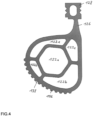
- the sealing section 120 has a plurality of tubular first hollow chambers 122a to 122e running parallel to the lower edge 118 of the door leaf 104 .
- These hollow chambers 122a to 122e are in particular arranged parallel to one another.
- a central hollow chamber 122a is preferably provided, which is surrounded in the manner of a satellite by further hollow chambers 122b to 122e, viewed in the circumferential direction.
- FIG 5 12 is a cross-sectional view of a pivoting/sliding door assembly 108 according to another embodiment having a lower door seal 116 according to FIG 2 and 3 , wherein the door leaf 104 and the sliding step 142 are in the extended position.
- the sealing section 120 has, at least in the region of the contact surface 138, an outwardly projecting first toothing 156 running transversely to the movement of the door leaf 104, which in the course of the closing process engages with a second toothing 158 running transversely to the movement of the door leaf 104 on the tread 114 engages.
- the first toothing 156 in turn disengages from the second toothing 158 .
- the engagement and disengagement is enabled by the elastic properties of the sealing portion 120 .
- the lower door seal 116 can be designed in one piece with, for example, two side door seals fastened to the door leaf 104, for example by the meter, and continuously transition into these side door seals in, for example, curved sections.
- the lower door seal 116 can also be attached to the lower edge 118 or in the area of the lower edge 118 of the door leaf 104 by an adjustment device (not shown here) in such a way that a vertical position of the lower door seal 166 in relation to the lower edge 118 of the door leaf 104 can be adjusted.
Description
Die Erfindung geht aus von einer Schwenkschiebetürvorrichtung zur Anordnung in einer Türöffnung eines Fahrzeugs, insbesondere eines Schienenfahrzeugs, gemäß dem Oberbegriff von Anspruch 1. Weiterhin betrifft die Erfindung auch ein Schienenfahrzeug mit wenigstens einer solchen Schwenkschiebetürvorrichtung gemäß Anspruch 22.The invention is based on a pivoting sliding door device for arrangement in a door opening of a vehicle, in particular a rail vehicle, according to the preamble of claim 1. The invention also relates to a rail vehicle with at least one such pivoting sliding door device according to claim 22.
Fahrzeuge zum Massentransport von Personen weisen oftmals Schwenkschiebetüren oder Faltklapptüren auf, durch welche Passagiere in das Fahrzeug ein- und aussteigen können. Bei einer solchen Schwenkschiebetüre öffnet und schließt sich der wenigstens eine Türflügel durch eine Kombination von einer ersten Bewegungsrichtung und einer zweiten Bewegungsrichtung, wobei die erste Bewegungsrichtung senkrecht zu einer Außenfläche des Fahrzeugs und die zweite Bewegungsrichtung parallel zur Außenfläche des Fahrzeugs ist. Dadurch kann in platzsparender Weise die Türöffnung freigeben werden und am oder im Fahrzeug wartende Personen werden nicht durch ein Ausschwenken des Türflügels behindert. Durch die Verwendung von Schwenkschiebetüren wird daher erreicht, dass das Ein- und Aussteigen der Passagiere schnell vonstattengehen kann. Eine weitere Anforderung an solche Schwenkschiebetürvorrichtungen besteht darin, den Innenraum des Fahrzeugs mit Hilfe einer Türdichtungsvorrichtung nach außen abzudichten.Vehicles for mass transportation of people often have pivoting sliding doors or folding doors through which passengers can enter and exit the vehicle. In such a pivoting sliding door, the at least one door leaf opens and closes through a combination of a first direction of movement and a second direction of movement, the first direction of movement being perpendicular to an outer surface of the vehicle and the second direction of movement being parallel to the outer surface of the vehicle. As a result, the door opening can be released in a space-saving manner and people waiting on or in the vehicle are not impeded by the door leaf swinging out. The use of pivoting sliding doors therefore ensures that the passengers can get on and off quickly. A further requirement of such pivoting and sliding door devices is to seal off the interior of the vehicle from the outside with the aid of a door sealing device.
Eine gattungsgemäße Schwenkschiebetürvorrichtung bzw. ein gattungsgemäßes Schienenfahrzeug sind aus
Der vorliegenden Erfindung liegt demgegenüber die Aufgabe zugrunde, eine Schwenkschiebetürvorrichtung der eingangserwähnten Art derart weiter zu bilden, dass sie bei einfacher Ausbildung der Türdichtungsvorrichtung eine hohe Dichtwirkung gegenüber einer Trittfläche erreicht wird. Weiterhin soll auch ein Schienenfahrzeug mit einer solchen Schwenkschiebetürvorrichtung zur Verfügung gestellt werden.In contrast, the present invention is based on the object of further developing a pivoting sliding door device of the type mentioned at the outset in such a way that a high sealing effect is achieved with respect to a tread surface with a simple design of the door sealing device. Furthermore, a rail vehicle with such a pivoting sliding door device is also to be made available.
Diese Aufgabe wird erfindungsgemäß durch die Merkmale der Ansprüche 1 und 22 gelöst. Vorteilhafte Weiterbildungen der Erfindung sind Gegenstand der beigefügten Unteransprüche.This object is achieved according to the invention by the features of claims 1 and 22. Advantageous developments of the invention are the subject matter of the appended dependent claims.
Die Erfindung geht aus von einer Schwenkschiebetürvorrichtung zur Anordnung in einer zur Anordnung in einer Türöffnung eines Fahrzeugs, insbesondere eines Schienenfahrzeugs, mit
- a) einem Türrahmen,
- b) wenigstens einer Schwenkschiebetür, welche einen gegenüber dem Türrahmen beweglichen Türflügel aufweist, welcher derart am Türrahmen zwischen einer Türflügel-Schließposition und einer Türflügel-Öffnungsposition gelagert ist, dass die Bewegungsrichtung des Türflügels während eines Öffnungsvorgangs und während eines Schließvorgangs im Wesentlichen in der Horizontalen verläuft,
- c) einer Türschwelle mit einer gegenüber der Horizontalen geneigt angeordneten Trittfläche für ein- und aussteigende Personen,
- d) einer Türdichtungsvorrichtung mit einer passiven unteren Türdichtung, welche einen Spalt zwischen einer Unterkante des Türflügels und der Trittfläche abdichtet, wobei
- e) die untere Türdichtung an der Unterkante oder im Bereich der Unterkante des Türflügels befestigt und in der Türflügel-Schließposition mit einem Dichtabschnitt gegen die geneigte Trittfläche dichtet.
- a) a door frame,
- b) at least one pivoting sliding door, which has a door leaf that can be moved relative to the door frame and is mounted on the door frame between a door leaf closed position and a door leaf open position in such a way that the direction of movement of the door leaf runs essentially horizontally during an opening process and during a closing process ,
- c) a door sill with a step surface arranged at an angle to the horizontal for people entering and exiting,
- d) a door sealing device with a passive lower door seal which seals a gap between a lower edge of the door leaf and the step surface, wherein
- e) the lower door seal is fastened to the lower edge or in the region of the lower edge of the door leaf and seals against the inclined tread surface with a sealing section in the door leaf closed position.
Wie bereits eingangs erwähnt, öffnet und schließt sich bei einer solchen Schwenkschiebetüre der wenigstens eine Türflügel durch eine Kombination einer ersten Bewegungsrichtung mit einer zweiten Bewegungsrichtung, wobei die erste Bewegungsrichtung senkrecht zu einer Außenfläche des Fahrzeugs und die zweite Bewegungsrichtung parallel zur Außenfläche des Fahrzeugs ist.As already mentioned at the beginning, the at least one door leaf in such a pivoting sliding door opens and closes by a combination of a first direction of movement and a second direction of movement, the first direction of movement being perpendicular to an outer surface of the vehicle and the second direction of movement being parallel to the outer surface of the vehicle.
Durch die gegenüber der Horizontalen geneigten Trittfläche der Türschwelle kann der Ein- und Ausstieg stufenlos und barrierefrei gestaltet werden.The tread surface of the door sill, which is inclined relative to the horizontal, allows stepless and barrier-free entry and exit.
- f) der Dichtabschnitt wenigstens eine schlauchförmige, parallel zur Unterkante des Türflügels verlaufende erste Hohlkammer aufweist, welche in der Türflügel-Öffnungsposition einen ersten Querschnitt und in der Türflügel-Schließposition einen zweiten, gegenüber dem ersten Querschnitt verformten Querschnitt aufweist, und dassf) the sealing section has at least one tubular first hollow chamber running parallel to the lower edge of the door leaf, which has a first cross section in the open position of the door leaf and a second cross section that is deformed compared to the first cross section in the closed position of the door leaf, and that
- g) bei der Schwenkschiebetür ein einziger Türflügel (einflügelige Schwenkschiebetürvorrichtung) oder zwei Türflügel (zweiflügelige Schwenkschiebetürvorrichtung) vorgesehen sind, wobei die zwei Türflügel zum Schließen der Türöffnung aufeinander zu und zum Freigeben der Türöffnung voneinander weglaufen.g) the swing-sliding door has a single door leaf (single-leaf swing-sliding door device) or two door leaves (double-leaf swing-sliding door device), the two door leaves running towards one another to close the door opening and away from one another to release the door opening.
Verformt bedeutet in diesem Zusammenhang einerseits, dass sich die Form des Querschnitts der Hohlkammer ändert und beispielsweise durch den Kontakt mit der Trittfläche der Türschwelle flacher wird. Beispielsweise findet beim Schließvorgang des Türflügels in die Türflügel-Schließposition senkrecht zur Trittfläche gesehen eine Kompression bzw. eine Verkleinerung und parallel zur Trittfläche gesehen eine Verlängerung des Querschnitts des Dichtabschnitts bzw. von dessen wenigstens einer ersten Hohlkammer statt. Weiterhin kann sich - muss aber nicht - auch das Volumen des Querschnitts der wenigstens einen ersten Hohlkammer infolge einer Kompression des Dichtabschnitts bzw. von dessen wenigstens einer ersten Hohlkammer ändern und insbesondere kleiner werden.In this context, deformed means, on the one hand, that the shape of the cross section of the hollow chamber changes and becomes flatter, for example, through contact with the tread surface of the door sill. For example, during the closing process of the door leaf into the door leaf closed position, the cross section of the sealing section or its at least one first hollow chamber is compressed or reduced perpendicularly to the tread surface and parallel to the tread surface is lengthened. Furthermore, the volume of the cross section of the at least one first hollow chamber can - but does not have to - change and in particular become smaller as a result of compression of the sealing section or of its at least one first hollow chamber.
Die wenigstens eine erste Hohlkammer ist bevorzugt in sich geschlossen und kann evakuiert, mit Luft unter atmosphärischem Umgebungsdruck oder unter einem gegenüber dem atmosphärischen Umgebungsdruck niedrigeren Druck oder mit einem anderen elastischen Medium befüllt sein, beispielsweise mit einem Schaumstoff.The at least one first hollow chamber is preferably self-contained and can be evacuated, filled with air at ambient atmospheric pressure or at a pressure lower than ambient atmospheric pressure, or with another elastic medium, for example with a foam.
Die wenigstens eine erste Hohlkammer ist von einer im Querschnitt gesehen umlaufenden Wandung des Dichtabschnitts umgeben, welche ebenfalls aus einem elastischen Material besteht, insbesondere aus einem Elastomer.The at least one first hollow chamber is surrounded by a circumferential wall of the sealing section, viewed in cross section, which wall also consists of an elastic material, in particular an elastomer.
Dadurch kann sich der Dichtabschnitt bestens elastisch verformen, wenn der Türflügel der Schwenkschiebetüre während eines Schließvorgangs im Wesentlichen in der Horizontalen verläuft und dadurch der Dichtabschnitt mit der gegenüber der Horizontalen geneigten Trittfläche in Kontakt tritt. Die in dem Dichtabschnitt ausgebildete wenigstens eine erste Hohlkammer bewirkt dann eine gute Schmiegung des Dichtabschnitts gegenüber der Trittfläche, was sich positiv auf die Dichtwirkung auswirkt. Weiterhin ergeben sich dann auch geringere Anforderungen an einzuhaltende Toleranzen zwischen dem Türflügel und der Trittfläche. Nicht zuletzt sorgt auch die gegenüber der Horizontalen geneigte, nach Art einer Rampe ausgebildete Trittfläche für eine weiter verbesserte Schmiegung des Dichtabschnitts gegenüber der Trittfläche, weil beim Schließvorgang dann der Dichtabschnitt gegen die rampenförmige Trittfläche entgegen deren Steigung aufläuft.As a result, the sealing section can deform elastically in the best possible way when the door leaf of the pivoting sliding door runs essentially horizontally during a closing process and the sealing section thereby comes into contact with the tread surface inclined relative to the horizontal. The at least one first hollow chamber formed in the sealing section then causes the sealing section to conform well to the tread surface, which has a positive effect on the sealing effect. Furthermore, then there are also lower requirements for tolerances to be maintained between the door leaf and the step surface. Last but not least, the tread surface, which is inclined relative to the horizontal and designed like a ramp, ensures further improved osculation of the sealing section relative to the tread surface, because during the closing process the sealing section then runs against the ramp-shaped tread surface against its slope.
Durch die Unteransprüche sind vorteilhafte Weiterbildungen der in Anspruch 1 angegebenen Erfindung möglich.Advantageous developments of the invention specified in claim 1 are possible as a result of the dependent claims.
Beispielsweise weist der Dichtabschnitt mehrere schlauchförmige, parallel zur Unterkante des Türflügels verlaufende erste Hohlkammern auf, welche insbesondere parallel zueinander angeordnet sind. Dabei kann beispielsweise eine zentrale Hohlkammer vorgesehen sein, welche an in Umfangsrichtung gesehen von weiteren Hohlkammern umgeben ist.For example, the sealing section has a plurality of tubular first hollow chambers which run parallel to the lower edge of the door leaf and are arranged in particular parallel to one another. In this case, for example, a central hollow chamber can be provided, which is surrounded by further hollow chambers as viewed in the circumferential direction.
Besonders bevorzugt sind die Bewegung des Türflügels während des Schließvorgangs, die Neigung der Trittfläche gegenüber der Horizontalen und der Dichtabschnitt derart ausgeführt und aufeinander abgestimmt sind, dass ausgehend von der Türflügel-Öffnungsposition, in welcher der erste unverformte Querschnitt der ersten Hohlkammer vorliegt, sich am Ende eines ersten Abschnitts des Schließvorgangs des Türflügels der Dichtabschnitt an die Trittfläche mit einer Kontaktfläche anlegt, und dass während eines sich an den ersten Abschnitt zeitlich anschließenden zweiten Abschnitts des Schließvorgangs dann der Dichtabschnitt mit seiner Kontaktfläche an der Trittfläche im Wesentlichen haften bleibt und sich der Türflügel weiter in Richtung Tür-Schließposition bewegt, und wenn dann am Ende des zweiten Abschnitts des Schließvorgangs die Türflügel-Schließposition durch den Türflügel endgültig erreicht ist, dann die erste Hohlkammer den zweiten, verformten Querschnitt einnimmt. Dies bringt den Vorteil neben der oben bereits erwähnten guten Schmiegung mit sich, dass dann ein Verschleiß des Dichtabschnitts der unteren Türdichtung infolge von Gleitbewegungen gegenüber der Trittfläche stak reduziert bzw. vermieden wird.The movement of the door leaf during the closing process, the inclination of the tread surface relative to the horizontal and the sealing section are designed and coordinated in such a way that starting from the door leaf open position, in which the first non-deformed cross section of the first hollow chamber is present, is particularly preferred at the end a first section of the closing process of the door leaf, the sealing section rests against the tread surface with a contact surface, and that during a second section of the closing process, which follows the first section in time, the sealing section then remains essentially stuck with its contact surface on the tread surface and the door leaf continues to move moved in the direction of the door-closed position, and when the door leaf-closed position is finally reached by the door leaf at the end of the second section of the closing process is, then the first hollow chamber occupies the second, deformed cross-section. In addition to the good osculation already mentioned above, this has the advantage that wear and tear on the sealing section of the lower door seal as a result of sliding movements relative to the tread surface is then greatly reduced or avoided.
Gemäß einer Weiterbildung wird ein Formschluss erzielt, wenn der Dichtabschnitt wenigstens im Bereich der Kontaktfläche eine nach außen ragende erste, quer zur Bewegung des Türflügels verlaufende Verzahnung aufweist, welche im Laufe des Schließvorgangs mit einer zweiten, quer zur Bewegung des Türflügels verlaufenden Verzahnung an der Trittfläche in Eingriff gerät. Im Laufe des Öffnungsvorgangs des Türflügels gerät dann die erste Verzahnung mit der zweiten Verzahnung wieder außer Eingriff, was durch die elastischen Eigenschaften des Dichtabschnitts ermöglicht wird.According to a further development, a form fit is achieved if the sealing section has, at least in the area of the contact surface, an outwardly projecting first toothing running transversely to the movement of the door leaf, which, during the closing process, engages with a second toothing running transversely to the movement of the door leaf on the tread surface gets engaged. In the course of the opening process of the door leaf, the first toothing then disengages from the second toothing again, which is made possible by the elastic properties of the sealing section.
Damit ergibt sich eine verbesserte Dichtwirkung, denn durch den Formschluss wird ein "Wegrutschen" des Dichtabschnitts von der Trittfläche verhindert. Durch die Verzahnung wird ein Abrollen des Dichtungsabschnitts auf der Trittfläche beim Schlie-ßen der Tür auch bei ungünstigen Reibungsverhältnissen (Reinigungsmittel, Verunreinigungen, etc.) sichergestellt.This results in an improved sealing effect, because the form fit prevents the sealing section from "slipping" off the tread surface. The toothing ensures that the sealing section rolls off the tread surface when the door is closed, even if the friction conditions are unfavorable (cleaning agents, dirt, etc.).
Gemäß einer weiterbildenden Maßnahme weist die untere Türdichtung einen sich an den Dichtabschnitt insbesondere vertikal anschließenden Stegabschnitt insbesondere aus Vollmaterial auf, welcher wiederum insbesondere vertikal in einen Halteabschnitt übergeht, welcher an der Unterkante des Türflügels insbesondere lösbar befestigt ist.According to a further development measure, the lower door seal has a web section, in particular made of solid material, which in particular vertically adjoins the sealing section and which in turn transitions in particular vertically into a holding section which is in particular detachably fastened to the lower edge of the door leaf.
Dabei kann an der Unterkante des Türflügels eine Stützvorrichtung derart angeordnet sein, dass zumindest der Stegabschnitt während des Schließvorgangs in einer Gegenrichtung in Bezug zur Bewegungsrichtung des Türflügels abgestützt ist. Dass beim Schließvorgang dann der Stegabschnitt an der Stützvorrichtung abgestützt ist, sorgt dafür, dass sich der Stegabschnitt dann infolge der Einfahrbewegung des Türflügels nicht mehr verformen kann, aber sich dann der Dichtabschnitt mit der ersten Hohlkammer maximal verformen kann, um eine weiter verbesserte Schmiegung und Dichtwirkung zu erzielen.A support device can be arranged on the lower edge of the door leaf in such a way that at least the web section is supported during the closing process in a direction opposite to the direction of movement of the door leaf. The fact that the web section is then supported on the support device during the closing process ensures that the web section can no longer deform as a result of the retracting movement of the door leaf, but that the sealing section with the first hollow chamber can then deform to the maximum, in order to achieve a further improved osculation and sealing effect to achieve.
In besonders zu bevorzugender Weise sind der Dichtabschnitt, der Stegabschnitt und der Halteabschnitt der unteren Türdichtung einstückig aus einem Elastomer-Material ausgebildet und bildet damit beispielsweise ein Extrusionsprofil, insbesondere als ablängbare Meterware.In a particularly preferred manner, the sealing section, the web section and the retaining section of the lower door seal are made in one piece from an elastomeric material formed and thus forms, for example, an extrusion profile, in particular as cut to length piece goods.
Der Halteabschnitt ist dann beispielsweise in einer nutartigen Ausnehmung an der Unterkante des Türfügels formschlüssig aufgenommen, wobei die nutartige Ausnehmung einen hinterschnittenen Querschnitt aufweist, in welchen der Halteabschnitt formschlüssig eingreift. Dieser formschlüssige Eingriff des Halteabschnitts in die nutartige Ausnehmung kann beispielsweise dadurch erreicht werden, dass der Halteabschnitt unter elastischer Verformung in die nutartige Ausnehmung eingepresst wird und sich dann aufgrund seiner Elastizität in der montierten Endstellung wieder innerhalb der nutartigen Ausnehmung aufweitet, wobei dann der hinterschnittene Querschnitt für den Formschluss sorgt. Eine separate Befestigungseinrichtung ist dann nicht erforderlich. Vielmehr werden für die Befestigung die elastischen Eigenschaften des Halteabschnitts genutzt.The holding section is then accommodated in a form-fitting manner, for example, in a groove-like recess on the lower edge of the door leaf, the groove-like recess having an undercut cross-section in which the holding section engages in a form-fitting manner. This form-fitting engagement of the holding section in the groove-like recess can be achieved, for example, by the holding section being pressed into the groove-like recess with elastic deformation and then expanding again within the groove-like recess due to its elasticity in the assembled end position, in which case the undercut cross-section then ensures the form closure. A separate fastening device is then not required. Rather, the elastic properties of the holding section are used for the attachment.
Gemäß einer Weiterbildung weist der Halteabschnitt eine zweite schlauchartige Hohlkammer auf. Diese zweite Hohlkammer erhöht dann die Elastizität des Halteabschnitts der unteren Türdichtung und erleichtert somit die oben beschriebene Montage. Die zweite Hohlkammer verläuft insbesondere parallel zur Unterkante des Türflügels.According to a development, the holding section has a second hose-like hollow chamber. This second hollow chamber then increases the elasticity of the holding section of the lower door seal and thus facilitates the assembly described above. The second hollow chamber runs in particular parallel to the lower edge of the door leaf.
Die Trittfläche der Türschwelle weist gegenüber der Horizontalen bevorzugt einen ersten Winkel α in einem Bereich von 10 Grad bis 15 Grad, weiter bevorzugt etwa 14 Grad auf.The tread surface of the door sill preferably has a first angle α in a range of 10 degrees to 15 degrees, more preferably about 14 degrees, relative to the horizontal.
Gemäß einer Weiterbildung kann eine Schiebetrittanordnung zur Überbrückung eines Spalts zwischen der Türschwelle und einem in Bezug auf das Fahrzeug externen begehbaren Bereich vorgesehen sein, welche einen zwischen einer eingefahrenen Schiebetritt-Ausgangsposition und einer ausgefahrenen Schiebetritt-Endposition linear antreibbaren Schiebetritt umfasst, wobei der Schiebetritt unterhalb der Türschwelle ein- und ausschiebbar geführt oder gelagert ist.According to a further development, a sliding step arrangement can be provided for bridging a gap between the door sill and an area that can be walked on externally in relation to the vehicle, which comprises a sliding step that can be driven linearly between a retracted starting position and an extended end position of the sliding step, with the sliding step below the Door threshold can be pushed in and out or stored.
Beispielsweise werden solche Schiebetrittanordnungen bei Fahrzeugen zur Personenbeförderung eingesetzt, um den Zu- und Ausstieg zu erleichtern und um eine Gefährdung von Personen zu vermeiden. Dabei kann der Schiebetritt mit Hilfe eines Antriebs zwischen der eingefahrenen Schiebetritt-Ausgangsposition (Ruhestellung) und der ausgefahrenen Schiebetritt-Endposition (Arbeitsstellung) hin- und her bewegt werden und ist hierzu beispielsweise an zwei parallel zueinander angeordneten Schienen einer Führungseinrichtung geführt. Üblicherweise geschieht die Führung des Schiebetritts über Rollen.For example, such sliding step arrangements are used in vehicles for passenger transport in order to make it easier to get on and off and to avoid endangering people. The sliding step can be moved back and forth with the help of a drive between the retracted sliding step starting position (rest position) and the extended sliding step end position (working position) and is for this purpose, for example, on two parallel arranged Out of a guide device rails. The sliding step is usually guided via rollers.
Beispielsweise bei einem Schienenfahrzeug dient der Schiebetritt der Schiebetrittanordnung zur Überbrückung des Spalts zwischen dem Schienenfahrzeug und einem Bahnsteig, wenn das Schienenfahrzeug in einem Bahnhof hält. Damit wird verhindert, dass Passagiere in den betreffenden Spalt hineintreten. Auch kann der Schiebetritt bei Omnibussen dazu dienen, den Spalt zwischen Fahrzeug und einer Bordsteinkante abzudecken. Der Schiebetritt kann auch dazu dienen, einen Niveauunterschied zwischen einer Plattform des Fahrzeugs und dem Bahnsteig oder Gehsteig zu überbrücken, um einen Zu- und Ausstieg mit Rollstühlen und Kinderwagen zu erleichtern. Nicht zuletzt kann eine solche Schiebetrittanordnung auch bei Fahrzeugen zur Beförderung von kranken oder behinderten Personen eingesetzt werden, etwa, um durch den ausgefahrenen Schiebetritt einen Fahrweg für eine fahrbare Krankentrage oder einen Rollstuhl zwischen einer Fahrzeugplattform und einer Straße oder einem Gehweg zu bilden. Der Schiebetritt bildet daher in der ausgefahrenen Schiebetritt-Endposition eine begehbare Fläche zwischen Fahrzeug und Bahnsteig und dient als Einstiegshilfe für Personen beim Betreten bzw. Verlassen des Fahrzeugs.For example, in a rail vehicle, the sliding step of the sliding step arrangement is used to bridge the gap between the rail vehicle and a platform when the rail vehicle stops at a station. This prevents passengers from stepping into the relevant gap. The sliding step on buses can also be used to cover the gap between the vehicle and a curb. The sliding step can also be used to bridge a difference in level between a platform of the vehicle and the platform or sidewalk in order to facilitate entry and exit with wheelchairs and prams. Last but not least, such a sliding step arrangement can also be used in vehicles for transporting sick or disabled people, for example to form a path for a mobile stretcher or a wheelchair between a vehicle platform and a road or a sidewalk through the extended sliding step. The sliding step therefore forms a walkable area between the vehicle and the platform in the extended sliding step end position and serves as a boarding aid for people when entering or exiting the vehicle.
Beispielsweise wird der Schiebetritt mit Hilfe einer Schiebetritt-Antriebseinrichtung zwischen der eingefahrenen Schiebetritt-Ausgangsposition (Ruhestellung) und der vollständig ausgefahrenen ausgefahrenen Schiebetritt-Endposition (Arbeitsstellung) hin- und her bewegt, kann aber auch an einer beliebigen Zwischenposition gestoppt und gehalten werden.For example, the sliding step is moved back and forth with the help of a sliding step drive device between the retracted sliding step starting position (rest position) and the fully extended extended sliding step end position (working position), but can also be stopped and held at any intermediate position.
Der Schiebetritt kann insbesondere in einer Schiebetrittkassette oder einem Schiebetrittgestell verschiebbar geführt sein, wobei dann die Schiebetrittkassette oder das Schiebetrittgestell in Gebrauchslage unterhalb der Türschwelle angeordnet ist.The sliding step can in particular be slidably guided in a sliding step cassette or a sliding step frame, in which case the sliding step cassette or the sliding step frame is arranged below the door sill in the position of use.
In Kombination mit der Schiebetrittanordnung kann eine Abstreifereinrichtung vorgesehen sein, welche eine an einem freien Ende der Trittfläche um eine horizontale Achse schwenkbare Klappe aufweist, welche dazu ausgebildet und vorgesehen ist, um zum Abstreifen von Schmutz und Bilden einer Rampe auf dem Schiebetritt in der Schiebetritt-Ausgangsposition, in der Schiebetritt-Endposition wie auch in Schiebetritt-Zwischenpositionen zwischen der Schiebetritt-Ausgangsposition und der Schiebetritt-Endposition aufzuliegen. Die Klappe bildet dann insbesondere eine Verlängerung der Trittfläche bzw. der Türschwelle. Weiterhin geht beispielsweise die Trittfläche der Türschwelle stufenlos in eine in Gebrauchslage obere Fläche der Klappe über, was einen weiterhin stufenlosen und barrierefreien Ein- und Ausstieg mit sich bringt.In combination with the sliding step arrangement, a scraper device can be provided which has a flap which can be pivoted about a horizontal axis at a free end of the step surface and which is designed and provided for scraping off dirt and forming a ramp on the sliding step in the sliding step Starting position, rest in the sliding step end position as well as in sliding step intermediate positions between the sliding step starting position and the sliding step end position. The flap then forms in particular an extension of the step surface or the door sill. Furthermore, for example, the tread of the door sill steplessly into an upper surface of the flap in the position of use, which entails stepless and barrier-free entry and exit.
Die Klappe kann insbesondere ausgebildet sein, um einen Spalt zwischen einer in Gebrauchslage unteren Fläche der Türschwelle und einer in Gebrauchslage oberen Fläche des Schiebetritts abzudichten.The flap can be designed in particular to seal a gap between a lower surface of the door sill in the position of use and an upper surface of the sliding step in the position of use.
In "Gebrauchslage oben bzw. unten" bedeutet die Ausrichtung der betreffenden Fläche oder Komponente in Bezug zur Vertikalen im Gebrauchszustand oder im montierten Zustand der Schwenkschiebetürvorrichtung.In "position of use up or down" means the orientation of the relevant surface or component in relation to the vertical in the state of use or in the assembled state of the pivoting sliding door device.
Besonders bevorzugt weist die Klappe gegenüber der oberen Fläche des Schiebetritts einen zweiten Winkel β in einem Bereich von 20 Grad bis 40 Grad auf.More preferably, the flap has a second angle β in a range of 20 degrees to 40 degrees relative to the top surface of the sliding step.
Zur schwenkbaren Lagerung der Klappe gegenüber der Türschwelle kann eine Gelenkverbindung zwischen der Klappe und dem freien Ende der Türschwelle vorgesehen sein. Diese Gelenkverbindung kann Vorspannmittel enthalten, durch welche die Klappe gegen die in Gebrauchslage obere Fläche des Schiebetritts vorgespannt wird.A hinged connection between the flap and the free end of the door sill can be provided for the pivotable mounting of the flap relative to the door sill. This articulated connection can contain prestressing means, by means of which the flap is prestressed against the upper surface of the sliding step in the position of use.
Gemäß einer besonders zu bevorzugenden Maßnahme steht die Klappe in der Türflügel-Schließposition unter dem Dichtabschnitt der unteren Türdichtung vor und kontaktiert den Dichtabschnitt nicht. Dadurch wird verhindert, dass ansonsten die Ausfahrbewegung des Schiebetritts durch den Dichtabschnitt behindert werden würde.According to a measure that is particularly preferable, the flap projects below the sealing section of the lower door seal in the door leaf closed position and does not contact the sealing section. This prevents the extension movement of the sliding step from being impeded by the sealing section.
Gemäß einer Weiterbildung bildet die untere Türdichtung einen unteren Abschnitt einer umlaufenden Türdichtung der Türdichtungsvorrichtung, welche an dem Umfang des Türflügels umlaufend ausgebildet ist.According to a further development, the lower door seal forms a lower section of a peripheral door seal of the door sealing device, which is formed peripherally on the circumference of the door leaf.
Nicht zuletzt kann die untere Türdichtung einstückig mit wenigstens einer seitlichen Türdichtung ausgeführt sein, welche ebenfalls am Türflügel befestigt ist, wobei die untere Türdichtung in die wenigstens eine seitliche Türdichtung in einem gebogenen Abschnitt kontinuierlich übergeht.Last but not least, the lower door seal can be made in one piece with at least one side door seal, which is also attached to the door leaf, the lower door seal continuously merging into the at least one side door seal in a curved section.
Weiterhin kann die untere Türdichtung an der Unterkante oder im Bereich der Unterkante des Türflügels durch eine Einstellvorrichtung derart befestigt sein, dass eine vertikale Lage der unteren Türdichtung in Bezug auf die Unterkante des Türflügels einstellbar ist.Furthermore, the lower door seal can be fastened to the lower edge or in the area of the lower edge of the door leaf by an adjustment device in such a way that a vertical position of the lower door seal can be adjusted in relation to the lower edge of the door leaf.
Alternativ hierzu kann die untere Türdichtung an der Unterkante oder im Bereich der Unterkante des Türflügels derart befestigt sein, dass eine vertikale Lage der unteren Türdichtung in Bezug auf die Unterkante des Türflügels festgelegt ist. Die untere Türdichtung ist dann nicht einstellbar.As an alternative to this, the lower door seal can be attached to the lower edge or in the area of the lower edge of the door leaf in such a way that a vertical position of the lower door seal is fixed in relation to the lower edge of the door leaf. The lower door seal is then not adjustable.
Die Erfindung betrifft auch ein Schienenfahrzeug mit wenigstens einer oben beschriebenen Schwenkschiebetürvorrichtung. Der bevorzugte Einsatz der erfindungsgemäßen Schwenkschiebetürvorrichtung ist daher in einem Schienenfahrzeug, worunter ein spurgebundenes Fahrzeug zu verstehen ist, wie etwa eine Lokomotive, ein Triebzug, ein Triebwagen, eine Straßenbahn, ein U-Bahnfahrzeug, ein Waggon wie ein Personen- bzw. Reisezug und/oder Güterwagen, insbesondere ein Hochgeschwindigkeits-Schienenfahrzeug. Alternativ könnte die erfindungsgemäße Schwenkschiebetürvorrichtung natürlich auch in einem straßengebundenen Fahrzeug eingesetzt werden, beispielsweise in einem Omnibus.The invention also relates to a rail vehicle with at least one pivoting sliding door device as described above. The preferred use of the pivoting and sliding door device according to the invention is therefore in a rail vehicle, which is to be understood as meaning a rail-bound vehicle, such as a locomotive, a multiple unit, a railcar, a tram, a subway vehicle, a wagon such as a passenger or passenger train and/or or goods wagons, especially a high-speed rail vehicle. Alternatively, the pivoting sliding door device according to the invention could of course also be used in a road vehicle, for example in a bus.
Die Erfindung wird nachstehend anhand von Ausführungsbeispielen unter Bezugnahme auf die beigefügte Zeichnung näher beschrieben. Es zeigen:
- Fig.1
- eine schematische Darstellung eines Schienenfahrzeugs mit einem bevorzugten Ausführungsbeispiel einer Schwenkschiebetürvorrichtung der vorliegenden Erfindung mit einer bevorzugten Ausführungsform einer unteren Türdichtung;
- Fig.2
- eine Querschnittsdarstellung der Schwenkschiebetürvorrichtung von
Fig.1 mit einem Türflügel und einem Schiebetritt in jeweils eingefahrener Stellung; - Fig.3
- eine Querschnittsdarstellung der Schwenkschiebetürvorrichtung von
Fig.1 mit dem Türflügel und dem Schiebetritt in ausgefahrener Stellung; - Fig.4
- eine Querschnittsdarstellung einer unteren Türdichtung gemäß einer weiteren Ausführungsform;
- Fig.5
- eine Querschnittsdarstellung einer Schwenkschiebetürvorrichtung gemäß einer weiteren Ausführungsform, mit einer unteren Türdichtung gemäß
Fig. 4 und mit dem Türflügel und dem Schiebetritt in ausgefahrener Stellung.
- Fig.1
- a schematic representation of a rail vehicle with a preferred embodiment of a pivoting sliding door device of the present invention with a preferred embodiment of a lower door seal;
- Fig.2
- a cross-sectional view of the pivoting sliding door device of
Fig.1 with a door leaf and a sliding step in the retracted position; - Fig.3
- a cross-sectional view of the pivoting sliding door device of
Fig.1 with the door leaf and the sliding step in the extended position; - Fig.4
- a cross-sectional view of a lower door seal according to another embodiment;
- Fig.5
- a cross-sectional view of a pivoting sliding door device according to a further embodiment, with a lower door seal according to FIG
4 and with the door leaf and sliding step in the extended position.
Wenn die Türdichtungsvorrichtungen 106 aus mehreren Einzelabschnitten zusammengesetzt sind, beispielsweise aus geradlinigen Abschnitten und Eckabschnitten, können die Türdichtungsvorrichtungen 106 auch als Türdichtungssysteme bezeichnet werden.If the
Die Schwenkschiebetürvorrichtungen 108 weisen Schwenkschiebetüren auf, welche hier beispielsweise jeweils einen gegenüber dem zugeordneten Türrahmen 102 beweglichen Schwenkschiebe-Türflügel 104 aufweisen, kurz Türflügel 104, welcher derart am Türrahmen 102 zwischen einer Türflügel-Schließposition und einer Türflügel-Öffnungsposition gelagert ist, dass die Bewegungsrichtung des Türflügels 104 während eines Öffnungsvorgangs und während eines Schließvorgangs der Schwenkschiebetüre im Wesentlichen in der Horizontalen bzw. in einer horizontalen Ebene verläuft. Auch ist eine Schwenkachse der Türflügel 104 bevorzugt vertikal.The pivoting and sliding
Erkennbar in
Die untere Türdichtung 116 ist an der Unterkante 118 oder im Bereich der Unterkante 118 des Türflügels 104 befestigt und dichtet in der in
Der Dichtabschnitt 120 weist eine schlauchförmige, parallel zur Unterkante 118 des Türflügels 104 verlaufende erste Hohlkammer 122 auf, welche in der Türflügel-Öffnungsposition einen ersten unverformten Querschnitt (
Die erste Hohlkammer 122 ist von einer Wandung 124 des Dichtabschnitts 120 umgeben, welche hier beispielsweise relativ dünn ausgeführt ist. Die erste Hohlkammer 122 ist bevorzugt in sich geschlossen und kann evakuiert, mit Luft unter atmosphärischem Umgebungsdruck oder unter einem gegenüber dem atmosphärischen Umgebungsdruck niedrigeren oder höheren Druck oder mit einem anderen elastischen Medium als Luft befüllt sein, beispielsweise mit einem Schaumstoff.The first
Die erste Hohlkammer 122 ist weiterhin bezogen auf ihre Längserstreckung schlauchförmig und flexibel ausgeführt und kann bei ihrer Anordnung zwischen dem Türflügel 104 und dem Türrahmen 102 bei einer Schließbewegung des Türflügels 104 zusammengepresst werden, um einen sich zwischen Türflügel 104 und Türrahmen 102 bzw. Trittfläche 114 befindlichen Spalt abzudichten. Eine Längserstreckungsrichtung des Dichtabschnitts 120 mit der ersten Hohlkammer 122 ist gemäß diesem Ausführungsbeispiel geradlinig, so dass der Dichtabschnitt 120 mit der ersten Hohlkammer 122 der unteren Türdichtung 116 beispielsweise entlang der geradlinigen Unterkante 118 des Türflügels 104 angeordnet ist.The first
Bevorzugt weist wenigstens die untere Türdichtung 116 der Türdichtungsvorrichtung 106 einen sich an den Dichtabschnitt 120 insbesondere vertikal anschließenden Stegabschnitt 126 insbesondere aus Vollmaterial auf, welcher wiederum insbesondere vertikal in einen Halteabschnitt 128 übergeht, welcher an der Unterkante 118 des Türflügels 104 insbesondere lösbar befestigt ist. Der Stegabschnitt 126 ist dabei gegenüber dem Halteabschnitt 128 und dem Dichtabschnitt 120, welchen er vertikal zwischengeordnet ist, dünner ausgeführt. In besonders zu bevorzugender Weise sind der Dichtabschnitt 120, der Stegabschnitt 126 und der Halteabschnitt 128 wenigstens der unteren Türdichtung 116 einstückig aus einem Elastomer-Material ausgebildet und bildet damit beispielsweise einen einstückigen Spritzgussformling.Preferably, at least the
Der Halteabschnitt 128 ist dann beispielsweise in einer nutartigen Ausnehmung 134 an der Unterkante 118 des Türfügels 104 formschlüssig aufgenommen, wobei die nutartige Ausnehmung 134 einen hinterschnittenen Querschnitt aufweist, in welchen der Halteabschnitt 128 formschlüssig eingreift. Der formschlüssige Eingriff des Halteabschnitts 128 in die nutartige Ausnehmung 134 kann beispielsweise dadurch hervorgerufen werden, dass der Halteabschnitt 128 unter elastischer Verformung in die nutartige Ausnehmung 134 eingepresst wird und sich dann aufgrund seiner Elastizität in der montierten Endstellung wieder innerhalb der nutartigen Ausnehmung 134 aufweitet, wobei dann der hinterschnittene Querschnitt für den Formschluss sorgt.The holding
Der Halteabschnitt 128 weist beispielsweise eine zweite schlauchartige Hohlkammer 136 auf. Diese zweite Hohlkammer 136 erhöht dann die Elastizität des Halteabschnitts 128 der unteren Türdichtung 116 und erleichtert somit die oben beschriebene Montage. Die zweite Hohlkammer 136 verläuft beispielsweise geradlinig parallel zur Unterkante 118 des Türflügels 104.The holding
Wie durch einen Vergleich der Form des Dichtabschnitts 120 in
Demgegenüber weist die erste Hohlkammer 122 in der in gemäß
Besonders bevorzugt sind die Bewegung des Türflügels 104 während des Schließvorgangs in die Türflügel-Schließposition, die Neigung (erster Winkel a) der Trittfläche 114 gegenüber der Horizontalen und der Dichtabschnitt 120 und insbesondere der Reibkoeffizient einer Kontaktfläche 138 des Dichtabschnitts 120 mit der Trittfläche 114 derart ausgeführt bzw. ausgebildet bzw. aufeinander abgestimmt, dass ausgehend von der Türflügel-Öffnungsposition, in welcher der erste unverformte Querschnitt der ersten Hohlkammer 122 vorliegt, sich am Ende eines ersten Abschnitts des Schließvorgangs des Türflügels 104 der Dichtabschnitt 120 an die Trittfläche 114 mit seiner Kontaktfläche 138 anlegt, wodurch sich der Querschnitt der ersten Hohlkammer 122 bereits etwas verformt. Während eines sich an den ersten Abschnitt zeitlich anschließenden zweiten Abschnitts des Schließvorgangs bleibt dann der Dichtabschnitt 120 mit seiner Kontaktfläche 138 an der Trittfläche 114 im Wesentlichen haften, wobei sich aber das Türblatt 104 weiter in Richtung Tür-Schließposition bewegt, was eine weitere Verformung des Querschnitts der ersten Hohlkammer 122 bedingt. Ist dann am Ende des zweiten Abschnitts des Schließvorgangs die Türflügel-Schließposition (
An der Unterkante 118 des Türflügels 104 ist hier beispielsweise eine Stützvorrichtung 130, hier beispielsweise in Form einer von der Unterkante 118 nach unten ragenden Rippe derart angeordnet, dass beispielsweise der Stegabschnitt 126 während des Schließvorgangs des Türflügels 104 in einer Gegenrichtung in Bezug zur Bewegungsrichtung 132 des Türflügels 104 abgestützt ist, wobei die Bewegungsrichtung 132 des Türflügels 104 während des Schließvorgangs in
Beispielsweise kann die Schwenkschiebetürvorrichtung 108 eine Schiebetrittanordnung 140 zur Überbrückung eines Spalts zwischen der Türschwelle 112 und einem in Bezug auf das Schienenfahrzeug 100 externen Bahnsteig vorgesehen sein, welche einen zwischen einer eingefahrenen Schiebetritt-Ausgangsposition und einer ausgefahrenen Schiebetritt-Endposition linear antreibbaren Schiebetritt 142 umfasst, wobei der Schiebetritt 142 dann beispielsweise unterhalb der Türschwelle 112 ein- und ausschiebbar geführt oder gelagert ist.For example, the pivoting sliding
Der Schiebetritt 142 kann insbesondere in einer hier nicht gezeigten Schiebetrittkassette oder einem Schiebetrittgestell verschiebbar geführt sein, wobei dann die Schiebetrittkassette oder das Schiebetrittgestell in Gebrauchslage unterhalb der Türschwelle 112 angeordnet ist.The sliding
In Kombination mit der Schiebetrittanordnung 140 ist hier eine Abstreifereinrichtung 144 vorgesehen, welche eine an einem freien Ende der Trittfläche 114 um eine horizontale Achse schwenkbare Klappe 146 aufweist, welche dazu ausgebildet und vorgesehen ist, um zum Abstreifen von Schmutz und Bilden einer Rampe auf dem Schiebetritt 142 in der Schiebetritt-Ausgangsposition, in der Schiebetritt-Endposition wie auch in Schiebetritt-Zwischenpositionen zwischen der Schiebetritt-Ausgangsposition und der Schiebetritt-Endposition aufzuliegen. Die Klappe 146 bildet dann insbesondere eine Verlängerung der Trittfläche 114 bzw. der Türschwelle 112. Weiterhin geht die Trittfläche 114 der Türschwelle 112 beispielsweise stufenlos in eine in Gebrauchslage obere Fläche 148 der Klappe 146 über.In combination with the sliding
Die Klappe 146 kann insbesondere ausgebildet sein, um einen Spalt zwischen einer in Gebrauchslage unteren Fläche 150 der Türschwelle 112 und einer in Gebrauchslage oberen Fläche 152 des Schiebetritts 142 abzudichten.The
Besonders bevorzugt weist die Klappe 146 gegenüber der oberen Fläche 152 des Schiebetritts 142 einen zweiten Winkel β in einem Bereich von 20 Grad bis 40 Grad auf.More preferably, the
Zur schwenkbaren Lagerung der Klappe 146 gegenüber der Türschwelle 112 ist hier beispielsweise eine Gelenkverbindung 154 zwischen der Klappe 146 und dem freien Ende der Türschwelle 112 vorgesehen sein. Diese Gelenkverbindung 154 kann Vorspannmittel enthalten, durch welche die Klappe 146 gegen die in Gebrauchslage obere Fläche 152 des Schiebetritts 142 vorgespannt wird.For the pivotable mounting of the
Besonders bevorzugt steht die Klappe 146 in der Türflügel-Schließposition unter dem Dichtabschnitt 120 der unteren Türdichtung 116 vor und kontaktiert den Dichtabschnitt 120 nicht. Dadurch wird verhindert, dass die Ausfahrbewegung des Schiebetritts 142 durch den Dichtabschnitt 120 behindert wird.The
Gemäß einer in
Wie leicht vorstellbar ist, kann die untere Türdichtung 116 einstückig mit beispielsweise zwei am Türflügel 104 befestigten seitlichen Türdichtungen beispielsweise als Meterware ausgeführt sein und in diese seitlichen Türdichtungen in beispielsweise gebogenen Abschnitten kontinuierlich übergehen.As can easily be imagined, the
Auch kann die untere Türdichtung 116 an der Unterkante 118 oder im Bereich der Unterkante 118 des Türflügels 104 durch eine hier nicht gezeigte Einstellvorrichtung derart befestigt sein, dass eine vertikale Lage der unteren Türdichtung 166 in Bezug auf die Unterkante 118 des Türflügels 104 einstellbar ist.The
Im Rahmen der Erfindung sind auch Ausführungen enthalten, welche beliebige Kombination von hier beschriebenen Merkmalen enthalten, die innerhalb des Schutzumfangs der Ansprüche sind.Also included within the scope of the invention are embodiments containing any combination of features described herein that are within the scope of the claims.
- 100100
- Schienenfahrzeugrail vehicle
- 102102
- Türrahmendoor frame
- 104104
- Türflügeldoor leaf
- 106106
- Türdichtungsvorrichtungdoor sealing device
- 108108
- SchwenkschiebetürvorrichtungPivoting sliding door device
- 112112
- Türschwelledoorstep
- 114114
- Trittflächetread
- 116116
- untere Türdichtunglower door seal
- 118118
- Unterkantebottom edge
- 120120
- Dichtabschnittsealing section
- 122, 122a-122e122, 122a-122e
- erste Hohlkammernfirst cavities
- 124124
- Wandungwall
- 126126
- Stegabschnittweb section
- 128128
- Halteabschnittholding section
- 130130
- Stützvorrichtungsupport device
- 132132
- Bewegungsrichtung SchließvorgangDirection of movement of the closing process
- 134134
- Ausnehmungrecess
- 136136
- zweite Hohlkammersecond cavity
- 138138
- Kontaktflächecontact surface
- 140140
- Schiebetrittanordnungsliding step arrangement
- 142142
- Schiebetrittsliding step
- 144144
- Abstreifereinrichtungwiper device
- 146146
- Klappeflap
- 148148
- obere Flächeupper surface
- 150150
- untere Flächelower surface
- 152152
- obere Flächeupper surface
- 154154
- Gelenkverbindungjoint connection
- 156156
- erste Verzahnungfirst gearing
- 158158
- zweite Verzahnungsecond toothing
Claims (22)
- Sliding plug door device (108) for arrangement in a door opening of a door opening of a vehicle (100), havinga) a door frame (102),b) at least one sliding plug door, which has a door leaf (104) which is movable relative to the door frame and is mounted on the door frame (102) between a door leaf closed position and a door leaf open position such that the movement direction of the door leaf (104) extends substantially horizontally during an opening process and during a closing process,c) a door sill (112) of the door frame (102) having a tread (114) which is inclined to the horizontal, for persons entering and alighting,d) a door seal device (106) having a passive lower door seal (116) which seals a gap between a lower edge (118) of the door leaf (104) and the tread (114), whereine) the lower door seal (116) is fastened to the lower edge (118) or in the region of the lower edge (118) of the door leaf (104) and seals by a sealing section (120) against the inclined tread (114) when the door leaf is in the closed position, characterised in thatf) the sealing section (120) has at least one tubular first cavity (122; 122a-122e) which runs parallel to the lower edge (118) of the door leaf (104) and has a first non-deformed cross-section when the door leaf is in the open position and a second cross-section, which is deformed in comparison with the first cross-section, when the door leaf is in the closed position, and in thatg) a single door leaf (104) or two door leaves is/are provided at the sliding plug door, wherein the two door leaves move towards each other to close the door opening and away from each other to release the door opening.
- Sliding plug door device according to claim 1, characterised in that the movement (132) of the door leaf (104) during the closing process, the inclination of the tread (114) relative to the horizontal, and the sealing section (120) are designed and adapted to one another such that, starting from the door leaf open position in which the first non-deformed cross-section of the at least one first cavity (122; 122a-122e) is present, at the end of a first section of the closing process of the door leaf (104) the sealing section (120) bears against the tread (114) with a contact surface (138), and that during a second section of the closing process subsequent to the first section, then the sealing section (120) remains substantially adhered to the tread (114) with its contact surface (138) and the door leaf (104) moves further in the direction of the door closed position and, when the door leaf closed position is finally reached by the door leaf (104) at the end of the second section of the closing process, the at least one first cavity (122; 122a-122e) adopts the second deformed cross-section.
- Sliding plug door device according to claim 2, characterised in that the sealing section (120) has at least in the region of the contact surface (138) an outwardly protruding first toothing (156) which extends transversely to the movement of the door leaf (104) and which during the course of the closing process is brought into engagement with a second toothing (158) on the tread (114) extending transversely to the movement of the door leaf (104) and during the course of the opening process is brought out of engagement.
- Sliding plug door device according to any of the preceding claims. characterised in that the lower door seal (116) has a web section (126), in particular made of solid material and adjoining the sealing section (120), said web section merging into a retaining section (128) which is, in particular releasably, fastened to the lower edge (118) of the door leaf (104).
- Sliding plug door device according to claim 4, characterised in that a support device (130) is arranged on the lower edge (118) of the door leaf (104) such that during the closing process at least the web section (126) is supported in an opposing direction relative to the movement direction (132) of the door leaf (104).
- Sliding plug door device according to claim 4 or 5, characterised in that the sealing section (120), the web section (126) and the retaining section (128) are configured integrally from an elastomer material.
- Sliding plug door device according to claim 6, characterised in that the retaining section (128) is positively located in a groove-like recess (134) on the lower edge (118) of the door leaf (104), wherein the groove-like recess (134) has an undercut cross-section with which the retaining section (128) positively engages.
- Sliding plug door device according to any of claims 4 to 7, characterised in that the retaining section (128) has at least one second tubular cavity (136).
- Sliding plug door device according to any of the preceding claims, characterised in that the tread (114) of the door sill (112) has a first angle (α) ranging from 10 degrees to 15 degrees relative to the horizontal.
- Sliding plug door device according to any of the preceding claims, characterised in that it has a sliding step arrangement (140) for bridging a gap between the door sill (112) and a walkable region which is external relative to the vehicle (100), said sliding step arrangement comprising a sliding step (142) which may be driven between a retracted sliding step initial position and an extended sliding step end position, wherein the sliding step (142) is mounted in a retractable and extendable manner below the door sill (112).
- Sliding plug door device according to claim 10, characterised in that it has a scraper device (144) which has at a free end of the tread (114) a flap (146) which is pivotable about a horizontal axis and which is configured and provided in order to be positioned for scraping dirt and forming a ramp on the sliding step (142) in the sliding step initial position, in the sliding step end position and also in the sliding step intermediate positions between the sliding step initial position and the sliding step end position.
- Sliding plug door device according to claim 11, characterised in that the flap (146) is configured to seal a gap between a lower surface (150) of the door sill (112) in the position of use and an upper surface (152) of the sliding step (142) in the position of use.
- Sliding plug door device according to claim 12, characterised in that the flap (146) has a second angle (β) ranging from 20 degrees to 40 degrees relative to the upper surface (152) of the sliding step (142).
- Sliding plug door device according to any of claims 11 to 13, characterised in that an articulated connection (154) is provided between the flap (146) and the free end of the door sill (112).
- Sliding plug door device according to any of claims 11 to 14, characterised in that in the door leaf closed position the flap (146) protrudes below the sealing section (120) of the lower door seal (116) and is not in contact with the sealing section (120).
- Sliding plug door device according to any of the preceding claims, characterised in that the lower door seal (116) forms a lower section of a peripheral door seal of the door seal device (106) which is arranged in a peripheral manner on the periphery of the door leaf (104).
- Sliding plug door device according to any of the preceding claims, characterised in that the sealing section (120) has a plurality of tubular first cavities (122a-122e) which run parallel to the lower edge (118) of the door leaf (104) and which are arranged, in particular, parallel to one another.
- Sliding plug door device according to claim 17, characterised in that a central cavity (122a) is provided, said central cavity being surrounded by further cavities (122b-122e) when viewed in the peripheral direction.
- Sliding plug door device according to any of the preceding claims, characterised in that the lower door seal (116) is designed integrally with at least one lateral door seal and merges continuously therein in a curved section.
- Sliding plug door device according to any of the preceding claims, characterised in that the lower door seal (116) lower door seal (116) is fastened to the lower edge (118) or in the region of the lower edge (118) of the door leaf (104) by an adjusting device, such that a vertical position of the lower door seal (166) is adjustable relative to the lower edge (118) of the door leaf (104).
- Sliding plug door device according to any of the preceding claims, characterised in that the lower door seal (116) lower door seal (116) is fastened to the lower edge (118) or in the region of the lower edge (118) of the door leaf (104), such that a vertical position of the lower door seal (166) is fixed relative to the lower edge (118) of the door leaf (104).
- Rail vehicle (100) having at least one sliding plug door device (108) according to any of the preceding claims.
Applications Claiming Priority (2)
| Application Number | Priority Date | Filing Date | Title |
|---|---|---|---|
| DE102018008139.8A DE102018008139B4 (en) | 2018-10-15 | 2018-10-15 | Pivoting sliding door device for arrangement in a door opening of a vehicle |
| PCT/EP2019/074973 WO2020078650A1 (en) | 2018-10-15 | 2019-09-18 | Pivoting and sliding door device for arrangement in a door opening of a door frame of a vehicle |
Publications (2)
| Publication Number | Publication Date |
|---|---|
| EP3867122A1 EP3867122A1 (en) | 2021-08-25 |
| EP3867122B1 true EP3867122B1 (en) | 2023-07-19 |
Family
ID=68062911
Family Applications (1)
| Application Number | Title | Priority Date | Filing Date |
|---|---|---|---|
| EP19773770.3A Active EP3867122B1 (en) | 2018-10-15 | 2019-09-18 | Pivoting and sliding door device for arrangement in a door opening of a door frame of a vehicle |
Country Status (7)
| Country | Link |
|---|---|
| US (1) | US20210380147A1 (en) |
| EP (1) | EP3867122B1 (en) |
| CN (1) | CN112867654A (en) |
| DE (1) | DE102018008139B4 (en) |
| ES (1) | ES2960594T3 (en) |
| PL (1) | PL3867122T3 (en) |
| WO (1) | WO2020078650A1 (en) |
Families Citing this family (2)
| Publication number | Priority date | Publication date | Assignee | Title |
|---|---|---|---|---|
| JP7279651B2 (en) * | 2020-01-22 | 2023-05-23 | トヨタ自動車株式会社 | Vehicle door seal structure |
| DE102022118452A1 (en) * | 2021-08-04 | 2023-02-09 | Bode - Die Tür Gmbh | Door system for a public transport vehicle |
Family Cites Families (14)
| Publication number | Priority date | Publication date | Assignee | Title |
|---|---|---|---|---|
| FR2264958B1 (en) * | 1974-03-21 | 1978-12-29 | Westinghouse Brake & Signal | |
| DE3710451A1 (en) * | 1987-03-30 | 1988-10-20 | Kiekert Gmbh Co Kg | Telescopic swinging-sliding door for rail vehicles |
| DE20311653U1 (en) * | 2003-07-29 | 2003-10-02 | Bode Gmbh & Co Kg | Sealing device on a pivoting sliding door for vehicles for passenger transport, in particular rail vehicles |
| EP1643071A1 (en) * | 2004-09-29 | 2006-04-05 | Cardo Door Ab | Sliding door comprising a section joint profile and method of making a sliding door |
| DE202008002914U1 (en) * | 2008-02-29 | 2009-07-09 | Gebr. Bode GmbH & Co. KG Fahrzeugtürsysteme | sealing device |
| CA2834597C (en) * | 2011-04-15 | 2015-12-22 | Ultrafab, Inc. | Multiple hollow bulb seal |
| DE102014208288A1 (en) * | 2014-05-02 | 2015-11-05 | Siemens Aktiengesellschaft | Printer-enabled door for a rail vehicle of high-speed traffic |
| DE202014104110U1 (en) * | 2014-09-02 | 2014-09-16 | Knorr-Bremse Gmbh | Door seal device, door seal system and door leaf for a rail vehicle |
| SG11201705784UA (en) * | 2015-01-15 | 2017-08-30 | Planet Gdz Ag | Seal for a sill-free door |
| DE102016112862A1 (en) * | 2016-07-13 | 2018-01-18 | Bombardier Transportation Gmbh | Door device and mounting method for this |
| DE102016013797A1 (en) * | 2016-11-21 | 2018-05-24 | Knorr-Bremse Gesellschaft Mit Beschränkter Haftung | Door module for arrangement in a door opening of a car body of a vehicle |
| CN206503509U (en) * | 2017-02-17 | 2017-09-19 | 扬州碧源人防工程有限公司 | A kind of explosion proof door for being easy to vehicle pass-through |
| DE102017002018A1 (en) * | 2017-03-03 | 2018-09-06 | Knorr-Bremse Gesellschaft Mit Beschränkter Haftung | Schiebetrittanordnung for a motor vehicle or for a rail vehicle |
| CN108099561A (en) * | 2018-01-24 | 2018-06-01 | 扬州华通橡塑有限公司 | A kind of stopping sliding door sealing strip connects angle and processing method |
-
2018
- 2018-10-15 DE DE102018008139.8A patent/DE102018008139B4/en active Active
-
2019
- 2019-09-18 ES ES19773770T patent/ES2960594T3/en active Active
- 2019-09-18 PL PL19773770.3T patent/PL3867122T3/en unknown
- 2019-09-18 US US17/285,837 patent/US20210380147A1/en active Pending
- 2019-09-18 WO PCT/EP2019/074973 patent/WO2020078650A1/en unknown
- 2019-09-18 CN CN201980067944.1A patent/CN112867654A/en active Pending
- 2019-09-18 EP EP19773770.3A patent/EP3867122B1/en active Active
Also Published As
| Publication number | Publication date |
|---|---|
| DE102018008139A1 (en) | 2020-04-16 |
| DE102018008139B4 (en) | 2022-01-05 |
| EP3867122A1 (en) | 2021-08-25 |
| US20210380147A1 (en) | 2021-12-09 |
| CN112867654A (en) | 2021-05-28 |
| ES2960594T3 (en) | 2024-03-05 |
| PL3867122T3 (en) | 2024-01-29 |
| WO2020078650A1 (en) | 2020-04-23 |
Similar Documents
| Publication | Publication Date | Title |
|---|---|---|
| EP3102473B1 (en) | Pressure-sealed door for a high-speed rail vehicle | |
| EP3589524B1 (en) | Sliding step assembly for a motor vehicle or for a rail vehicle | |
| EP3867122B1 (en) | Pivoting and sliding door device for arrangement in a door opening of a door frame of a vehicle | |
| EP3541678B1 (en) | Door module for arranging in a door opening of a wagon body of a vehicle | |
| DE102018105069B3 (en) | Roof arrangement for a vehicle roof and vehicle roof with a roof opening | |
| EP3121086A1 (en) | Rail vehicle with bridge element for bridging a gap between a door and a platform | |
| EP3663158A1 (en) | Step system for a vehicle | |
| DE4242624C2 (en) | Body part for a motor vehicle | |
| EP3213973A1 (en) | Entry system for a vehicle | |
| EP3810479B1 (en) | Gap-bridging device for a rail vehicle | |
| DE102016201275B3 (en) | Frontnotausstieg | |
| EP2060729A2 (en) | Corner seal for a window sash or door leaf | |
| DE102014013772B4 (en) | Vehicle with a vehicle door | |
| EP0940278B1 (en) | Telescopic mechanism for pivoting sliding doors of vehicles | |
| EP0931532A1 (en) | Ramp for vehicles | |
| EP1857085A2 (en) | Retractable ramp for vehicles in public urban and long-distance passenger transport networks | |
| AT505101A2 (en) | DOOR GUIDE AND DOOR MOUNTING SYSTEM FOR PASSENGER RAIL VEHICLES | |
| DE3536621C1 (en) | Guide-in buffer for pivotable doors, bonnets, flaps or the like of motor vehicles | |
| EP3303033B1 (en) | Shading device for a pane or a glass roof region of a vehicle interior | |
| DE3401390A1 (en) | Sliding door for vehicles or the like | |
| WO2018215392A1 (en) | Lift car for a lift installation and method for opening and closing a door opening | |
| DE102018104194A1 (en) | Horizontal frame part for a sliding door and / or sliding window frame, sliding door and / or sliding window frame as well as sliding door and / or sliding window system | |
| DE202018103171U1 (en) | Passive seal for a sliding door | |
| DE102016125784B4 (en) | Sliding step for a rail vehicle | |
| EP3812234B1 (en) | Passenger transport vehicle and step device for a passenger transport vehicle |
Legal Events
| Date | Code | Title | Description |
|---|---|---|---|
| STAA | Information on the status of an ep patent application or granted ep patent |
Free format text: STATUS: UNKNOWN |
|
| STAA | Information on the status of an ep patent application or granted ep patent |
Free format text: STATUS: THE INTERNATIONAL PUBLICATION HAS BEEN MADE |
|
| PUAI | Public reference made under article 153(3) epc to a published international application that has entered the european phase |
Free format text: ORIGINAL CODE: 0009012 |
|
| STAA | Information on the status of an ep patent application or granted ep patent |
Free format text: STATUS: REQUEST FOR EXAMINATION WAS MADE |
|
| 17P | Request for examination filed |
Effective date: 20210517 |
|
| AK | Designated contracting states |
Kind code of ref document: A1 Designated state(s): AL AT BE BG CH CY CZ DE DK EE ES FI FR GB GR HR HU IE IS IT LI LT LU LV MC MK MT NL NO PL PT RO RS SE SI SK SM TR |
|
| DAV | Request for validation of the european patent (deleted) | ||
| DAX | Request for extension of the european patent (deleted) | ||
| REG | Reference to a national code |
Ref document number: 502019008603 Country of ref document: DE Free format text: PREVIOUS MAIN CLASS: B61D0019000000 Ipc: B61D0019020000 Ref country code: DE Ref legal event code: R079 |
|
| GRAP | Despatch of communication of intention to grant a patent |
Free format text: ORIGINAL CODE: EPIDOSNIGR1 |
|
| STAA | Information on the status of an ep patent application or granted ep patent |
Free format text: STATUS: GRANT OF PATENT IS INTENDED |
|
| RIC1 | Information provided on ipc code assigned before grant |
Ipc: B60J 10/86 20160101ALI20230224BHEP Ipc: B60J 10/248 20160101ALI20230224BHEP Ipc: B60J 10/24 20160101ALI20230224BHEP Ipc: B61D 19/00 20060101ALI20230224BHEP Ipc: B61D 19/02 20060101AFI20230224BHEP |
|
| INTG | Intention to grant announced |
Effective date: 20230317 |
|
| GRAS | Grant fee paid |
Free format text: ORIGINAL CODE: EPIDOSNIGR3 |
|
| GRAA | (expected) grant |
Free format text: ORIGINAL CODE: 0009210 |
|
| STAA | Information on the status of an ep patent application or granted ep patent |
Free format text: STATUS: THE PATENT HAS BEEN GRANTED |
|
| AK | Designated contracting states |
Kind code of ref document: B1 Designated state(s): AL AT BE BG CH CY CZ DE DK EE ES FI FR GB GR HR HU IE IS IT LI LT LU LV MC MK MT NL NO PL PT RO RS SE SI SK SM TR |
|
| REG | Reference to a national code |
Ref country code: GB Ref legal event code: FG4D Free format text: NOT ENGLISH |
|
| REG | Reference to a national code |
Ref country code: CH Ref legal event code: EP |
|
| REG | Reference to a national code |
Ref country code: DE Ref legal event code: R096 Ref document number: 502019008603 Country of ref document: DE |
|
| REG | Reference to a national code |
Ref country code: IE Ref legal event code: FG4D Free format text: LANGUAGE OF EP DOCUMENT: GERMAN |
|
| PGFP | Annual fee paid to national office [announced via postgrant information from national office to epo] |
Ref country code: GB Payment date: 20230921 Year of fee payment: 5 |
|
| REG | Reference to a national code |
Ref country code: LT Ref legal event code: MG9D |
|
| REG | Reference to a national code |
Ref country code: NL Ref legal event code: MP Effective date: 20230719 |
|
| PGFP | Annual fee paid to national office [announced via postgrant information from national office to epo] |
Ref country code: FR Payment date: 20230918 Year of fee payment: 5 Ref country code: DE Payment date: 20230919 Year of fee payment: 5 |
|
| PG25 | Lapsed in a contracting state [announced via postgrant information from national office to epo] |
Ref country code: NL Free format text: LAPSE BECAUSE OF FAILURE TO SUBMIT A TRANSLATION OF THE DESCRIPTION OR TO PAY THE FEE WITHIN THE PRESCRIBED TIME-LIMIT Effective date: 20230719 |
|
| PG25 | Lapsed in a contracting state [announced via postgrant information from national office to epo] |
Ref country code: GR Free format text: LAPSE BECAUSE OF FAILURE TO SUBMIT A TRANSLATION OF THE DESCRIPTION OR TO PAY THE FEE WITHIN THE PRESCRIBED TIME-LIMIT Effective date: 20231020 |
|
| PGFP | Annual fee paid to national office [announced via postgrant information from national office to epo] |
Ref country code: ES Payment date: 20231019 Year of fee payment: 5 |
|
| PG25 | Lapsed in a contracting state [announced via postgrant information from national office to epo] |
Ref country code: IS Free format text: LAPSE BECAUSE OF FAILURE TO SUBMIT A TRANSLATION OF THE DESCRIPTION OR TO PAY THE FEE WITHIN THE PRESCRIBED TIME-LIMIT Effective date: 20231119 |
|
| PG25 | Lapsed in a contracting state [announced via postgrant information from national office to epo] |
Ref country code: SE Free format text: LAPSE BECAUSE OF FAILURE TO SUBMIT A TRANSLATION OF THE DESCRIPTION OR TO PAY THE FEE WITHIN THE PRESCRIBED TIME-LIMIT Effective date: 20230719 Ref country code: RS Free format text: LAPSE BECAUSE OF FAILURE TO SUBMIT A TRANSLATION OF THE DESCRIPTION OR TO PAY THE FEE WITHIN THE PRESCRIBED TIME-LIMIT Effective date: 20230719 Ref country code: PT Free format text: LAPSE BECAUSE OF FAILURE TO SUBMIT A TRANSLATION OF THE DESCRIPTION OR TO PAY THE FEE WITHIN THE PRESCRIBED TIME-LIMIT Effective date: 20231120 Ref country code: NO Free format text: LAPSE BECAUSE OF FAILURE TO SUBMIT A TRANSLATION OF THE DESCRIPTION OR TO PAY THE FEE WITHIN THE PRESCRIBED TIME-LIMIT Effective date: 20231019 Ref country code: LV Free format text: LAPSE BECAUSE OF FAILURE TO SUBMIT A TRANSLATION OF THE DESCRIPTION OR TO PAY THE FEE WITHIN THE PRESCRIBED TIME-LIMIT Effective date: 20230719 Ref country code: LT Free format text: LAPSE BECAUSE OF FAILURE TO SUBMIT A TRANSLATION OF THE DESCRIPTION OR TO PAY THE FEE WITHIN THE PRESCRIBED TIME-LIMIT Effective date: 20230719 Ref country code: IS Free format text: LAPSE BECAUSE OF FAILURE TO SUBMIT A TRANSLATION OF THE DESCRIPTION OR TO PAY THE FEE WITHIN THE PRESCRIBED TIME-LIMIT Effective date: 20231119 Ref country code: HR Free format text: LAPSE BECAUSE OF FAILURE TO SUBMIT A TRANSLATION OF THE DESCRIPTION OR TO PAY THE FEE WITHIN THE PRESCRIBED TIME-LIMIT Effective date: 20230719 Ref country code: GR Free format text: LAPSE BECAUSE OF FAILURE TO SUBMIT A TRANSLATION OF THE DESCRIPTION OR TO PAY THE FEE WITHIN THE PRESCRIBED TIME-LIMIT Effective date: 20231020 Ref country code: FI Free format text: LAPSE BECAUSE OF FAILURE TO SUBMIT A TRANSLATION OF THE DESCRIPTION OR TO PAY THE FEE WITHIN THE PRESCRIBED TIME-LIMIT Effective date: 20230719 |
|
| PGFP | Annual fee paid to national office [announced via postgrant information from national office to epo] |
Ref country code: CZ Payment date: 20230907 Year of fee payment: 5 |
|
| P01 | Opt-out of the competence of the unified patent court (upc) registered |
Effective date: 20240123 |
|
| REG | Reference to a national code |
Ref country code: ES Ref legal event code: FG2A Ref document number: 2960594 Country of ref document: ES Kind code of ref document: T3 Effective date: 20240305 |