EP3859754B1 - Supraleitender verdrillter verbunddraht und verfahren zum wiederaufwickeln desselben - Google Patents
Supraleitender verdrillter verbunddraht und verfahren zum wiederaufwickeln desselben Download PDFInfo
- Publication number
- EP3859754B1 EP3859754B1 EP19865613.4A EP19865613A EP3859754B1 EP 3859754 B1 EP3859754 B1 EP 3859754B1 EP 19865613 A EP19865613 A EP 19865613A EP 3859754 B1 EP3859754 B1 EP 3859754B1
- Authority
- EP
- European Patent Office
- Prior art keywords
- compound superconducting
- twisted wire
- compound
- superconducting
- strand
- Prior art date
- Legal status (The legal status is an assumption and is not a legal conclusion. Google has not performed a legal analysis and makes no representation as to the accuracy of the status listed.)
- Active
Links
Images


Classifications
-
- H—ELECTRICITY
- H01—ELECTRIC ELEMENTS
- H01B—CABLES; CONDUCTORS; INSULATORS; SELECTION OF MATERIALS FOR THEIR CONDUCTIVE, INSULATING OR DIELECTRIC PROPERTIES
- H01B12/00—Superconductive or hyperconductive conductors, cables, or transmission lines
- H01B12/02—Superconductive or hyperconductive conductors, cables, or transmission lines characterised by their form
- H01B12/08—Stranded or braided wires
-
- C—CHEMISTRY; METALLURGY
- C22—METALLURGY; FERROUS OR NON-FERROUS ALLOYS; TREATMENT OF ALLOYS OR NON-FERROUS METALS
- C22C—ALLOYS
- C22C9/00—Alloys based on copper
-
- C—CHEMISTRY; METALLURGY
- C22—METALLURGY; FERROUS OR NON-FERROUS ALLOYS; TREATMENT OF ALLOYS OR NON-FERROUS METALS
- C22C—ALLOYS
- C22C9/00—Alloys based on copper
- C22C9/02—Alloys based on copper with tin as the next major constituent
-
- H—ELECTRICITY
- H01—ELECTRIC ELEMENTS
- H01B—CABLES; CONDUCTORS; INSULATORS; SELECTION OF MATERIALS FOR THEIR CONDUCTIVE, INSULATING OR DIELECTRIC PROPERTIES
- H01B12/00—Superconductive or hyperconductive conductors, cables, or transmission lines
- H01B12/02—Superconductive or hyperconductive conductors, cables, or transmission lines characterised by their form
- H01B12/10—Multi-filaments embedded in normal conductors
-
- H—ELECTRICITY
- H01—ELECTRIC ELEMENTS
- H01F—MAGNETS; INDUCTANCES; TRANSFORMERS; SELECTION OF MATERIALS FOR THEIR MAGNETIC PROPERTIES
- H01F41/00—Apparatus or processes specially adapted for manufacturing or assembling magnets, inductances or transformers; Apparatus or processes specially adapted for manufacturing materials characterised by their magnetic properties
- H01F41/02—Apparatus or processes specially adapted for manufacturing or assembling magnets, inductances or transformers; Apparatus or processes specially adapted for manufacturing materials characterised by their magnetic properties for manufacturing cores, coils, or magnets
- H01F41/04—Apparatus or processes specially adapted for manufacturing or assembling magnets, inductances or transformers; Apparatus or processes specially adapted for manufacturing materials characterised by their magnetic properties for manufacturing cores, coils, or magnets for manufacturing coils
- H01F41/048—Superconductive coils
-
- H—ELECTRICITY
- H01—ELECTRIC ELEMENTS
- H01F—MAGNETS; INDUCTANCES; TRANSFORMERS; SELECTION OF MATERIALS FOR THEIR MAGNETIC PROPERTIES
- H01F6/00—Superconducting magnets; Superconducting coils
- H01F6/06—Coils, e.g. winding, insulating, terminating or casing arrangements therefor
-
- H—ELECTRICITY
- H10—SEMICONDUCTOR DEVICES; ELECTRIC SOLID-STATE DEVICES NOT OTHERWISE PROVIDED FOR
- H10N—ELECTRIC SOLID-STATE DEVICES NOT OTHERWISE PROVIDED FOR
- H10N60/00—Superconducting devices
- H10N60/01—Manufacture or treatment
- H10N60/0184—Manufacture or treatment of devices comprising intermetallic compounds of type A-15, e.g. Nb3Sn
-
- H—ELECTRICITY
- H10—SEMICONDUCTOR DEVICES; ELECTRIC SOLID-STATE DEVICES NOT OTHERWISE PROVIDED FOR
- H10N—ELECTRIC SOLID-STATE DEVICES NOT OTHERWISE PROVIDED FOR
- H10N60/00—Superconducting devices
- H10N60/20—Permanent superconducting devices
-
- H—ELECTRICITY
- H01—ELECTRIC ELEMENTS
- H01B—CABLES; CONDUCTORS; INSULATORS; SELECTION OF MATERIALS FOR THEIR CONDUCTIVE, INSULATING OR DIELECTRIC PROPERTIES
- H01B12/00—Superconductive or hyperconductive conductors, cables, or transmission lines
- H01B12/02—Superconductive or hyperconductive conductors, cables, or transmission lines characterised by their form
-
- Y—GENERAL TAGGING OF NEW TECHNOLOGICAL DEVELOPMENTS; GENERAL TAGGING OF CROSS-SECTIONAL TECHNOLOGIES SPANNING OVER SEVERAL SECTIONS OF THE IPC; TECHNICAL SUBJECTS COVERED BY FORMER USPC CROSS-REFERENCE ART COLLECTIONS [XRACs] AND DIGESTS
- Y02—TECHNOLOGIES OR APPLICATIONS FOR MITIGATION OR ADAPTATION AGAINST CLIMATE CHANGE
- Y02E—REDUCTION OF GREENHOUSE GAS [GHG] EMISSIONS, RELATED TO ENERGY GENERATION, TRANSMISSION OR DISTRIBUTION
- Y02E40/00—Technologies for an efficient electrical power generation, transmission or distribution
- Y02E40/60—Superconducting electric elements or equipment; Power systems integrating superconducting elements or equipment
Definitions
- Non-Patent Document 4 reports on the design and properties of a Nb 3 Sn wire strand developed for the International Thermonuclear Experimental Reactor (ITER). The internal-tin process was employed using 19 subelements, 6 spacers, and a Ta-containing barrier to separate the superconducting core from the Cu stabilizer. Further, said document discloses some aspects of conductor design and heat treatment, and how these affect the various properties including n value.
- Non-Patent Document 5 fabricates ITER/TPX-type bronze-route Nb-coated Nb 3 Sn strands using a co-processing technique as an alternative to the existing hard chrome plating method. Results show that a continuous Nb layer as thin as 2-3 um can be formed on the surface of TPX/ITER strands during strand processing. This Nb coating prevents the superconducting strands in a Cable-in-Conduit conductor from sintering during Nb 3 Sn reaction heat treatment. It was demonstrated that the Nb surface coating does not degrade the residual resistance ratio of the Cu stabilizer in the strand as well as the critical current density in superconducting filaments. The additional magnetization hysteresis loss due to the Nb surface coating is negligible when compared to the loss from Nb 3 Sn filaments in the strand.
- conventional compound superconducting twisted wire may be produced by a so-called react-and-wind process, in which a plurality of wires including a reinforcing material such as Cu-Nb are twisted to form a twisted wire, the twisted wire is subjected to heat treatment, then a pre-bending strain is applied to the twisted wire, and then the twisted wire is wound to form a superconducting coil. It is known that this process improves a critical current of the compound superconducting twisted wire which constitutes the superconducting coil.
- the compound superconducting twisted wire produced by conventional art as described above cannot be said to have a sufficient strength against tension, and there is a need to further enhance the strength.
- strands are likely to partially adhere to each other due to thermal fusion during heat treatment. If the strands are adhered to each other, it is not possible to apply a uniform bending strain to each of all the strands constituting the twisted wire during repeated application of pre-bending strains. Therefore, some strands may be easily subject to a large strain (or stress) in a compound superconductor part, resulting in damage.
- the compound superconducting twisted wire of the present invention adopts a configuration including a plurality of compound superconducting strands being twisted to form a twisted structure, in which each of the compound superconducting strands includes a core-like compound superconductor part, a cylindrical reinforcing part and a cylindrical stabilizing part, in which the core-like compound superconductor part includes a plurality of compound superconducting filaments and a first matrix, the compound superconducting filaments each including a compound superconducting phase, the first matrix including the plurality of compound superconducting filaments embedded therein and a first stabilizing material, in which the cylindrical reinforcing part is disposed on an outer circumferential side of the compound superconductor part, and includes a plurality of reinforcing filaments and a second matrix, the second matrix including the plurality of reinforcing filaments embedded therein and a second stabilizing material, in which the cylindrical stabilizing part is disposed on at least one side of an inner circumferential
- the compound superconducting twisted wire that has remarkably improved non-adhesiveness between compound superconducting strands or separation easiness after adhesion, while a strength against tension (in particular, 0.2% proof stress) is improved to a degree to be equivalent to or stronger than that of a conventional compound superconducting twisted wire.
- the compound superconducting twisted wire enables a superconducting coil to be commercially produced.
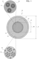
- FIG. 1 is a schematic diagram illustrating a cross section of a compound superconducting strand 10, taken out from the plurality of compound superconducting strands constituting the compound superconducting twisted wire before compression.
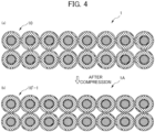
- FIGS. 4(a) and 4(b) are schematic diagrams illustrating cross sections of compound superconducting twisted wires, FIG. 4(a) illustrates a state of the compound superconducting twisted wire 1 before compression and FIG. 4(b) illustrates a state of the compound superconducting twisted wire 1A after compression with a cross section compression ratio of 6%.
- the compound superconducting twisted wire 1 shown in FIG. 4(a) is formed as a twisted structure in which a plurality of compound superconducting strands 10 is twisted together.
- FIG. 4(b) two tiers each including eight compound superconducting strands 10 arranged in parallel are stacked, so that a total of 16 compound superconducting strands are twisted together to form the twisted structure.
- These twisted structures have a substantially rectangular cross section shapes, and a case in which the compound superconducting twisted wire 1 is formed as a so-called rectangular Rutherford cable is indicated.
- the compound superconducting strand 10 mainly includes a compound superconductor part 11, a reinforcing part 12, and a stabilizing part 13.
- the compound superconductor part 11 includes a plurality of compound superconducting filaments 15 each including a compound superconducting phase, and a first matrix 16 in which the plurality of compound superconducting filaments 15 is embedded.
- the first matrix 16 includes a first stabilizing material.
- the compound superconductor part 11 forms a core-like shape as a whole.
- the compound superconducting phase is preferably a metal compound superconducting phase including Nb 3 Sn(niobium-tin), but is not limited thereto, and may be other compound superconducting phases, for example, including Nb 3 Al(niobium-aluminum) or having superconductive property.
- FIG. 1 shows the compound superconductor part 11 produced by a so-called bronze process, in which a plurality of Nb filaments are embedded in a first matrix precursor (first matrix before heat treatment) of Cu-Sn (copper-tin)-base alloy, which is the first stabilizing material, the embedded Nb filaments are subjected to drawing processing, etc. to form a compound superconducting precursor strand; the compound superconducting precursor strand is subjected to heat treatment; this diffuses Sn in the first matrix precursor and allows the Sn to react with surfaces of Nb filaments; and thereby an Nb 3 Sn filament is formed from the Nb filament.
- the compound superconductor part 11 indicates a case in which a core portion 17 of unreacted Nb remaining without reacting with Sn exists.
- the compound superconductor part 11 it is possible to produce the compound superconducting filament 15 after heat treatment as a filament in which the core portion 17 of unreacted Nb does not exist and all of which consists of Nb 3 Sn, depending on the amount of Sn contained in the first matrix precursor and a diameter size of the Nb filament before heat treatment.
- the Cu-Sn (copper-tin) base alloy which is the first stabilizing material, may contain elements other than Cu and Sn, but only in small amounts, and the Cu-Sn base alloy preferably contains, for example, Ti or the like in a range of 0.2 to 0.3 mass%.
- the volume ratio of the reinforcing part relative to the compound superconducting strand is preferably 40% or more and 65% or less.
- the reason for this is as follows: when the volume ratio of the reinforcing part is less than 40%, a strength under tension of the respective strands 10 may not be sufficiently increased, and therefore, when fusion (adhesion) occurs between the strands 10, the fusion portion may not be easily separated (peeled off); when the volume ratio of the reinforcing part is larger than 65%, the volume ratio of the compound superconductor part is too small, and therefore superconductive property may not be sufficiently ensured.
- not easily dissolve in Cu refers to the point that a metal or an alloy constituting the reinforcing filament 18 dissolves in Cu as a solid in a content of less than 1 at.% at a temperature during the heat treatment (e.g., 600°C to 750°C) to form the compound superconducting phase.
- the reinforcing part 12 in which a plurality of the reinforcing filaments 18 mainly containing a metallic material which does not easily dissolve in Cu as a solid are embedded in the second matrix 19, it is possible to suppress the formation (existence) of an intermetallic compound in the reinforcing filament 18 in the reinforcing part 12, and thereby to form a reinforcing member having high strength against tensile strain and bending strain.
- volume ratio is more than 15%, due to a large cross section compression ratio applied to strands in twisted wire molding processing, repulsion of the respective strands is too strong and a local variation of compression load is caused, resulting in a problem in the finished shape of the molded twisted wire.
- the total of the volume ratio (%) of the second stabilizing material constituting the reinforcing part 12 relative to the compound superconducting strand 10 and the volume ratio of the third stabilizing material constituting the stabilizing part 13 relative to the compound superconducting strand 10 is 50% or more.
- the stabilizing material refers to a material, generally a metal, which is electrically and/or thermally in contact with a superconductor so as to ensure thermal contact with a refrigerant and/or act as an electric shunt circuit, as defined in JIS H 7005: 2005.
- the stabilizing material refers to normal conducting metal material that is complexed to a superconductor to enhance stability of the superconductor.
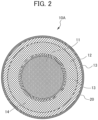
- FIG. 2 is a diagram illustrating the compound superconducting strand 10A used for constituting the compound superconducting twisted wire (not shown) of an embodiment according to the present invention
- the compound superconducting twisted wire of this embodiment is formed using the compound superconducting strand 10A shown in FIG. 2 , instead of the compound superconducting strand 10.
- the compound superconducting strand 10A has a metal layer 20 with a thickness of 0.5 um or less on the surface to prevent thermal fusion between the compound superconducting strands.
- the metal layer 20 can be produced not only by a wet plating method such as an electroplating method or an electroless plating method, but also by a dry plating method such as a chemical vapor deposition method or a physical vapor deposition method.
- the metal constituting the metal layer is chromium (Cr).
- Cr chromium
- it is formed a metal layer by Cr plating, because of excellent non-adhesiveness and abrasion resistance.
- the thickness of the metal layer 20 is 0.5 um or less.
- FIG. 1 is a diagram illustrating an embodiment of the compound superconducting strand 10 in which the Sn diffusion prevention part 14 in one layer is disposed between the compound superconductor part 11 and the reinforcing part 12, two more layers of Sn diffusion prevention parts 14a and 14b may be disposed.
- FIG. 3 is a drawing illustrating a compound superconducting strand 10B in which two layers of the Sn diffusion prevention parts 14a and 14b are disposed.
- a total of a volume ratio of the reinforcing filament 18 constituting the reinforcing part 12 relative to the compound superconducting strand 10 and a volume ratio of the Sn diffusion prevention part 14 relative to the compound superconducting strand 10 is preferably 150 or more.
- the total of the volume ratio of the reinforcing filament 18 constituting the reinforcing part 12 relative to the compound superconducting strand 10 and the volume ratio of the Sn diffusion prevention part 14 relative to the compound superconducting strand 10 is 16% or more and 23% or less. It should be noted that the upper limit of the total of the volume ratios is preferably 25% or less, from the viewpoint of avoiding the volume ratio of the compound superconductor part 11 becoming too small to ensure a critical current value of the compound superconducting strand 10.
- the total of the volume ratio of the compound superconductor part 11 and the volume ratio of the Sn diffusion prevention layer 14 is preferably 20% or more, and more preferably 30% or more.
- the total of the volume ratios is 20% or more, it is possible to obtain a practical critical current value of the superconducting twisted wire obtained by using the react-and-wind process.
- the compound superconducting twisted wire 1 may have a substantially rectangular cross section shape as shown in FIG. 4 (b) , which is formed as a so-called rectangular Rutherford twisted wire (cable), or may have a round cross section shape.
- the compound superconducting twisted wire has a substantially rectangular cross section shape
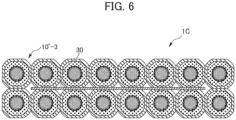
- a metal tape 30 between compound superconducting strands 10'-3, 10'-3 constituting a compound superconducting twisted wire 1C as shown in FIG. 6 , in order to prevent thermal fusion between the compound superconducting strands.
- a material of the metal tape 30 may be a heat-resistant metal, and it is preferable to use, for example, stainless steel such as SUS304 or SUS316L.
- the thickness of the metal tape 30 may be, for example, about 0.02 to 0.10 mm. It should be noted that although FIG. 4 (b) shows an embodiment in which two tiers each including a plurality of compound superconducting strands 10'-1 are stacked, three tiers or more may be stacked to form a rectangular Rutherford twisted wire. In this case, the metal tape can be disposed between neighboring tiers.
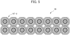
- the compound superconducting twisted wire preferably has cross section compression ratio of 5% or more and 20% or less.
- cross section compression ratio of 5% or more and 20% or less.
- FIGS. 4 to 6 are schematical drawings of the cross-sectional state of the compound superconducting twisted wires after compressing by varying the cross section compression ratios.
- FIG. 4 (a) is a drawing illustrating a cross-sectional state of the twisted wire before compression
- FIG. 4 (b) is a drawing illustrating a cross-sectional state of the twisted wire after compression at a cross section compression ratio of 6%
- FIG. 5 is a drawing illustrating a cross-sectional state of the twisted wire after compression at a cross section compression ratio of 12%
- FIG. 6 is a drawing illustrating a cross-sectional state of the twisted wire after compression at a cross section compression ratio of 12% while disposing the metal tape 30 between the compound superconducting strands 10'-3, 10'-3.
- the "cross section compression ratio” refers to a cross section compression ratio in the thickness direction.
- a cross section compression ratio of a median value in the width direction shall be used (by using an average value of a thickness of the thick edge and a thickness of the thin edge as the thickness t).
- the cross section compression ratio P is expressed by the following equation, in which t 1 (mm) after the compression is a total thickness of two neighboring strands which have been subject to the largest compression deformation in the cross section.
- P % 1 ⁇ t 1 / 2 ⁇ d ⁇ 100
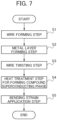
- FIG. 7 is a flow chart showing steps of the production method of the compound superconducting twisted wire of the present embodiment.
- the method for producing the compound superconducting twisted wire in the embodiment shown in FIG. 7 mainly includes a wire forming step S1, a metal layer forming step S2, a wire twisting step S3, a heat treatment step S4 to form the compound superconducting phase, and a bending strain application step S5.
- the method for producing the compound superconducting twisted wire of the present embodiment it is possible to produce coils by the react-and-wind process.
- the internal strain of the compound superconductor part 11 is controlled through a series of manufacturing steps S1 to S5 described above, and the wire is less likely to be damaged during the manufacturing.
- a method of use with regard to the winding direction when performing winding of a magnet has been clarified, it is possible to obtain excellent electrical conduction characteristics during operation of the produced magnet.
- the respective steps are described below.
- the wire forming step S1 is a step which includes:
- the metal layer forming step S2 is a step of forming a metal layer having a thickness of 0.5 um or less on the surface of a compound superconducting precursor strand to prevent thermal fusion between the compound superconducting precursor strands. This step may be omitted when the volume ratio of the reinforcing part relative to the compound superconducting strand is larger than the volume ratio of the compound superconductor part relative to the compound superconducting strand.
- a Cr plate layer as a metal layer is formed on the surface of the compound superconducting precursor strand by an electroplating method in which cathode current is conducted through the compound superconducting precursor strand immersed in a chromium plating solution.
- the wire twisting step S3 is a step of twisting a plurality of compound superconducting precursor strands together to produce the compound superconducting precursor twisted wire. Specifically, the wire twisting step S3 may be performed after twisting, the wire twisting step S3 including molding processing, such as rolling using a molding roll apparatus, to a predetermined shape such as a Rutherford cable.
- the heat treatment step S4 is a heat treatment step for forming a compound superconducting phase. After performing the heat treatment in the heat treatment step S4, when the temperature is lowered from the heat treatment temperature (e.g., 670°C, 96 hours) to room temperature (e.g., 25°C), compressive stress (compressive strain) remains in the Nb 3 Sn filaments constituting the compound superconductor part 11 and the Sn diffusion prevention part 14 including Ta, Nb, etc., due to difference in the thermal expansion coefficient of members constituting the wire.
- the heat treatment temperature e.g., 670°C, 96 hours
- room temperature e.g., 25°C
- tensile stress (tensile strain) remains in the first stabilizing material (Cu-Sn base alloy material) of the first matrix constituting the compound superconductor part 11, the second stabilizing material constituting the reinforcing part 12, and the third stabilizing material constituting the stabilizing part 13.
- the reinforcing part 12 can serve as a member to be subject to tension within the cross section of the wire. Therefore, the Nb 3 Sn filaments are less likely to be damaged.
- the bending strain application step S5 is a step in which bending procession is applied to the superconducting twisted wire W obtained in the heat treatment step S4, to add a predetermined bending strain.
- a bending strain application apparatus (not shown), the superconducting twisted wire wound around a heat treatment bobbin is linearly wound off without making the superconducting twisted wire rotate in the axial direction thereof, and then the superconducting twisted wire W is made to pass the two or more pulleys while applying an appropriate bending strain to the superconducting twisted wire W.
- the superconducting twisted wire W which is wound around the heat treatment bobbin 21 in an arc shape is wound off without making the superconducting twisted wire W to rotate axially and is linearly bent so as to be deformed, the superconducting twisted wire W is subject to bending strain ⁇ b-straight indicated in the following equation (1) due to a curved linear state.
- the reference dimension shall be the diameter d fb of the compound superconductor part (not including the Sn diffusion prevention part).
- each of the plurality of compound superconducting strands constituting the compound superconducting twisted wire of the present invention can move independently, and therefore the neutral line of bending strain was assumed to be at the center position of the compound superconductor part 11 constituted by the respective strands.
- the diameter d fb of the compound superconductor part (group of filaments) is replaced with the diameter d of a strand, a bending strain based on the strand surface can be obtained.
- [Mathematical Formula 1] ⁇ fb-straight ⁇ d fb ⁇ 1 D h + d ⁇ ⁇ d fb 1 D h
- the maximum strain applied to the compound superconductor part (group of filaments) 11 is equal to the sum of the maximum tensile bending strain due to the bending diameter and the tensile strain by tension in the axial direction which are applied during wire winding. That is, it is necessary for the maximum strain applied to the compound superconductor part 11 to not exceed the maximum strain under which damage does not occur to the compound superconducting filament 15. As indicated by the formula (3), it is important to control the maximum strain applied when the wire is bent to the reverse direction with respect to the bending direction during the heat treatment.
- the compound superconducting twisted wire 1 may be covered by winding an insulating tape on an outer circumferential surface of the twisted wire, after the wire twisting step or later in which the twisted wire has been formed. From the viewpoint of making the insulation tape not easily damaged, it is preferable to coat by winding the insulating tape after the heat treatment step for forming the compound superconducting phase or after the bending strain application step.
- the compound superconducting twisted wire W is rewound from a first winding member, e.g., the heat treatment bobbin 21, to a second winding member, e.g., a winding-up bobbin 24 for forming, for example, a superconducting coil, via a positive direction bending pulley 22 and a reverse direction bending pulley 23, it is preferred that the compound superconducting twisted wire W is wound off (unwound) from the heat treatment bobbin 21 in the tangential direction of the heat treatment bobbin 21 and wound up around the winding-up bobbin 24 while bending the compound superconducting twisted wire W in the same direction as the direction in which the compound superconducting twisted wire W has been wound around the heat treatment bobbin 21.
- a first winding member e.g., the heat treatment bobbin 21
- a second winding member e.g., a winding-up bobbin 24 for forming, for example, a
- values of d and d fb in the case of a round wire are replaced with d t and d fb t when the wire is bent in a flatwise direction and are replaced with d w and d fb w when the wire is bent in an edgewise direction.
- the compound superconducting twisted wire 1 of the present invention is preferably used for magnets for generating high magnetic field, semiconductor manufacturing apparatus, medical particle accelerators, magnets for scientific research, etc.
- the compound superconducting twisted wire 1 of the present invention it is possible to increase current-carrying capacity of the compound superconducting twisted wire 1 of the present invention, by using strands having a larger diameter or by increasing the number of twisted strands, in order to obtain an appropriate twisted wire depending upon the superconducting application apparatus. It is also possible to reduce an allowable bending diameter during twisting and winding, by reducing the diameter of the strand, and thereby, it is possible to obtain an appropriate twisted wire depending upon the superconducting application apparatus.
- the diameter of the compound superconducting strand 10 is preferably in the range of 0.2 mm or more and 2.0 mm or less. When the diameter of the strand is larger than 2.0 mm, flexibility is deteriorated, and thus the handling property tends to be poor. Further, when the diameter of the strand is smaller than 0.2 mm, the strength of the compound superconducting strand 10 itself is weakened, and the handling property tends to be poor.
- Nb filament which is a precursor of a compound superconducting filament before heat treatment, was embedded in a first matrix precursor, which was before being subjected to heat treatment and which consisted of Cu-14 mass% Sn-0.2 mass% Ti. A plurality of the above was bundled and twisted to form a compound superconducting precursor part.
- an Sn diffusion prevention part consisting of Ta was disposed around the outer circumference of the compound superconducting precursor part, a reinforcing part consisting of Cu-20 volume% Nb was disposed around the outer circumference thereof, and a stabilizing part consisting of oxygen free copper was further disposed around the outer circumference thereof to prepare an Nb 3 Sn superconducting precursor strand having a cross sectional structure with a diameter of 0.80 mm, as illustrated in FIG. 1 .
- the compound superconducting precursor part, the Sn diffusion prevention part, the reinforcing part, and the stabilizing part, which constitute the Nb 3 Sn superconducting precursor strand had a volume ratio of 21%, 4%, 60%, and 15%, respectively.
- the volume ratio of the reinforcing filament (Nb) relative to the reinforcing part was set to 20%. Thereafter, 16 Nb 3 Sn superconducting precursor strands were twisted together, followed by compression at a cross section compression ratio of 6% in the thickness direction, to produce the Nb 3 Sn superconducting precursor twisted wire having a rectangular cross section shape. At this time, the twisted wire was adjusted to have a conductor width of 6.45 mm and a twist pitch of 65 mm. Next, a heat treatment for forming a compound superconducting phase was performed at 670°C for 96 hours, and a bending strain was applied to produce the compound superconducting twisted wire. Bending strain application conditions are indicated below.
- a compound superconducting twisted wire having the same configuration as Example 1A (not covered by the present claims) was prepared, except that the strand had a cross-sectional structure shown in FIG. 2 ; the compound superconducting precursor part, the Sn diffusion prevention part, the reinforcing part, and the stabilizing part, which constitute the Nb 3 Sn superconducting precursor strand, had a volume ratio of 41%, 4%, 35%, and 20%, respectively; and a Cr plate layer with a thickness of 0.5 um is formed on the surface of the stabilizing part 13 of the strand.
- a compound superconducting twisted wire having the same configuration as Example 1A (not covered by the present claims) was prepared, except that the strand had a cross-sectional structure shown in FIG. 3 ; the compound superconducting precursor part, the Sn diffusion prevention part, the reinforcing part, and the stabilizing part, which constitute the Nb 3 Sn superconducting precursor strand, had a volume ratio of 22%, 8%, 50%, and 20%, respectively; the Sn diffusion prevention part included two layers of Ta layer and Nb layer; and the volume ratio of the reinforcing filament (Nb) relative to the reinforcing part was 30%.
- a compound superconducting twisted wire having the same configuration as Example 1A (not covered by the present claims) was prepared, except that the compound superconducting precursor part, the Sn diffusion prevention part, the reinforcing part, and the stabilizing part, which constitute the Nb 3 Sn superconducting precursor strand, had a volume ratio of 41%, 4%, 35%, and 20%, respectively.
- a compound superconducting twisted wire having the same configuration as Example 1A (not covered by the present claims) was produced, except that the cross section compression ratio after twisting was 12%.
- a compound superconducting twisted wire having the same configuration as Example 1B was produced, except that the cross section compression ratio after twisting was 12%.
- a compound superconducting twisted wire having the same configuration as Example 1C (not covered by the present claims) was produced, except that the cross section compression ratio after twisting was 12%.
- a compound superconducting twisted wire having the same configuration as Comparative Example 1 was produced, except that the cross section compression ratio after twisting was 12%.
- a compound superconducting twisted wire having the same configuration as Example 2A (not covered by the present claims) was produced, except that a metal tape including SUS316L with a thickness of 0.08 mm was disposed between the compound superconducting strands.
- a compound superconducting twisted wire having the same configuration as Example 3 (not covered by the present claims) was produced, except that the compound superconducting precursor part, the Sn diffusion prevention part, the reinforcing part, and the stabilizing part, which constitute the Nb 3 Sn superconducting precursor strand, had a volume ratio of 41%, 4%, 35%, and 20%, respectively.
- a compound superconducting twisted wire having the same configuration as Example 3 (not covered by the present claims) was produced, except that the compound superconducting precursor part, the Sn diffusion prevention part, the reinforcing part, and the stabilizing part, which constitute the Nb 3 Sn superconducting precursor strand, had a volume ratio of 41%, 4%, 35%, and 20%, respectively, and the bending strain application step was not performed.
- Non-adhesiveness (or easiness of separation after adhesion) of the strands constituting the compound superconducting twisted wire after the Nb 3 Sn superconducting formation heat treatment at 670°C for 96 hours was evaluated in four grades by the following test, in which a reciprocating bending strain of ⁇ 0.5% was applied to a surface of a sample strands cut to a length three times longer than the twist pitch and visually inspecting whether or not the strands are adhered to each other or separated (peeled off) from each other.
- the strands were rated as "1"; when the adhesion between the strands was recognized but the adhesion was unlikely to have an adverse effect during application of the bending strain, the strands were rated as "2"; when the adhesion between the strands was recognized and the adhesion was likely to have an adverse effect during application of the bending strain, the strands were rated as "3"; and when the adhesion between the strands was observed and the adhesion was obviously likely to have an adverse effect during application of the bending strain, the strands were rated as "4".
Landscapes
- Engineering & Computer Science (AREA)
- Chemical & Material Sciences (AREA)
- Power Engineering (AREA)
- Materials Engineering (AREA)
- Mechanical Engineering (AREA)
- Metallurgy (AREA)
- Organic Chemistry (AREA)
- Manufacturing & Machinery (AREA)
- Superconductors And Manufacturing Methods Therefor (AREA)
Claims (10)
- Verdrillter Verbundsupraleiterdraht (1) der eine Vielzahl von Verbundsupraleiterlitzen (10A) umfasst, die verdrillt sind, um eine verdrillte Struktur auszubilden,wobei jede der Verbundsupraleiterlitzen (10A) einen kernartigen Verbundsupraleiterteil (11), einen zylindrischen Verstärkungsteil (12) und einen zylindrischen Stabilisierungsteil (13) umfasst,wobei der kernartige Verbundsupraleiterteil (11) eine Vielzahl von Verbundsupraleiterfilamenten (15) und eine erste Matrix (16) umfasst, wobei die Verbundsupraleiterfilamente (15) jeweils eine Verbundsupraleiterphase umfassen, wobei die erste Matrix (16) die Vielzahl der darin eingebetteten Verbundsupraleiterfilamente (15) und ein erstes Stabilisierungsmaterial umfasst,wobei der zylindrische Verstärkungsteil (12) auf einer Außenumfangsseite des Verbundsupraleiterteils (11) angeordnet ist und eine Vielzahl von Verstärkungsfilamenten (18) und eine zweite Matrix (19) umfasst, wobei die zweite Matrix (19) die Vielzahl der darin eingebetteten Verstärkungsfilamente (18) und ein zweites Stabilisierungsmaterial umfasst, undwobei der zylindrische Stabilisierungsteil (13) auf mindestens einer Seite einer Innenumfangsseite und einer Außenumfangsseite des Verstärkungsteils (12) angeordnet ist und ein drittes Stabilisierungsmaterial umfasst, dadurch gekennzeichnet, dassder verdrillte Verbundsupraleiterdraht eine Cr-Beschichtung (20) mit einer Dicke von 0,5 µm oder weniger auf einer Oberfläche der Verbundsupraleiterlitze (10A) umfasst, um ein thermisches Verschmelzen zwischen den Verbundsupraleiterlitzen zu verhindern.
- Verdrillter Verbundsupraleiterdraht (1) nach Anspruch 1, ferner umfassend einen Sn-Diffusionsverhinderungsteil (14) zwischen dem Verbundsupraleiterteil (11) und dem Verstärkungsteil (12).
- Verdrillter Verbundsupraleiterdraht (1) nach Anspruch 2, wobeidie Verbundsupraleiterphase Nb3Sn umfasst,das erste Stabilisierungsmaterial Cu oder eine Cu-Legierung umfasst,der Sn-Diffusionsverhinderungsteil (14) Nb oder Ta oder eine Legierung oder einen Verbund davon umfasst,das Verstärkungsfilament mindestens ein Metall oder eine Legierung aus zwei oder mehr Metallen umfasst, die aus der Gruppe ausgewählt sind, die aus Nb, Ta, V, W, Mo, Fe, Ti, Ag und Hf besteht,das zweite Stabilisierungsmaterial Cu oder eine Cu-Legierung umfasst, unddas dritte Stabilisierungsmaterial Cu oder eine Cu-Legierung umfasst.
- Verdrillter Verbundsupraleiterdraht (1) nach einem der Ansprüche 1 bis 3,
wobei eine Summe eines Volumenverhältnisses des zweiten Stabilisierungsmaterials relativ zu der Verbundsupraleiterlitze (10A) und eines Volumenverhältnisses des dritten Stabilisierungsmaterials relativ zu der Verbundsupraleiterlitze (10A) 50 % oder mehr beträgt. - Verdrillter Verbundsupraleiterdraht (1) nach Anspruch 2,
wobei eine Summe eines Volumenverhältnisses des Verstärkungsfilaments relativ zu der Verbundsupraleiterlitze (10A) und eines Volumenverhältnisses des Sn-Diffusionsverhinderungsteils (14) relativ zu der Verbundsupraleiterlitze (10A) 15 % oder mehr beträgt. - Verdrillter Verbundsupraleiterdraht (1) nach einem der Ansprüche 1 bis 5,
wobei ein Volumenverhältnis des Verstärkungsfilaments relativ zu der Verbundsupraleiterlitze (10A) 11 % oder mehr und 15 % oder weniger beträgt. - Verdrillter Verbundsupraleiterdraht (1) nach einem der Ansprüche 1 bis 6,
wobei die verdrillte Struktur eine im Wesentlichen rechteckige Querschnittsform aufweist. - Verdrillter Verbundsupraleiterdraht (1) nach Anspruch 7, ferner umfassend ein Metallband (30) zur Verhinderung eines thermischen Verschmelzens zwischen den Verbundsupraleiterlitzen (10A),
wobei das Metallband (30) zwischen den Verbundsupraleiterlitzen (10A), die den verdrillten Verbundsupraleiterdraht (1) bilden, angeordnet ist. - Verdrillter Verbundsupraleiterdraht (1) nach Anspruch 7 oder 8,wobei die verdrillte Struktur ein Querschnittskompressionsverhältnis von 5 % oder mehr und 20 % oder weniger aufweist, wobeiwenn der verdrillte Verbundsupraleiterdraht ein verdrillter Rutherford-Draht mit einer im Wesentlichen rechteckigen Querschnittsform ist, in der n Lagen, welche jeweils eine Vielzahl von parallel angeordneten Verbundsupraleiterlitzen aufweisen, gestapelt sind, wobei der Durchmesser der Litze d (mm) ist und die Dicke des verdrillten Verbundsupraleiterdrahtes nach der Kompression t (mm) ist, das Querschnittskompressionsverhältnis P durch die folgende Gleichung dargestellt wird
 wenn es sich bei dem verdrillten Verbundsupraleiterdraht um einen rundförmigen verdrillten Draht handelt, das Querschnittskompressionsverhältnis P durch die folgende Gleichung ausgedrückt wird, in der t1 (mm) nach der Kompression die Gesamtdicke zweier benachbarter Litzen ist, die der größten Kompressionsverformung im Querschnitt ausgesetzt wurden,
- Verfahren zum Umspulen eines verdrillten Verbundsupraleiterdrahtes (1; W) gemäß einem der Ansprüche 1 bis 9 von einem ersten Wickelelement (21) zu einem zweiten Wickelelement (24), wobei das Verfahren umfasst:Abwickeln des verdrillten Verbundsupraleiterdrahtes (1; W) von dem ersten Wickelelement (21) in einer tangentialen Richtung des ersten Wickelelements (21); undWickeln des verdrillten Verbundsupraleiterdrahtes (1; W) um das zweite Wickelelement (24), wobei der verdrillte Verbundsupraleiterdraht (1; W) in dieselbe Richtung gebogen wird wie die Richtung, in der der verdrillte Verbundsupraleiterdraht (1; W) um das erste Wickelelement (21) gewickelt wurde.
Applications Claiming Priority (2)
| Application Number | Priority Date | Filing Date | Title |
|---|---|---|---|
| JP2018185632 | 2018-09-28 | ||
| PCT/JP2019/037012 WO2020066908A1 (ja) | 2018-09-28 | 2019-09-20 | 化合物超電導撚線およびその巻替え方法 |
Publications (3)
| Publication Number | Publication Date |
|---|---|
| EP3859754A1 EP3859754A1 (de) | 2021-08-04 |
| EP3859754A4 EP3859754A4 (de) | 2022-11-02 |
| EP3859754B1 true EP3859754B1 (de) | 2024-06-12 |
Family
ID=69950703
Family Applications (1)
| Application Number | Title | Priority Date | Filing Date |
|---|---|---|---|
| EP19865613.4A Active EP3859754B1 (de) | 2018-09-28 | 2019-09-20 | Supraleitender verdrillter verbunddraht und verfahren zum wiederaufwickeln desselben |
Country Status (4)
| Country | Link |
|---|---|
| US (1) | US12255000B2 (de) |
| EP (1) | EP3859754B1 (de) |
| JP (1) | JP7358688B2 (de) |
| WO (1) | WO2020066908A1 (de) |
Families Citing this family (3)
| Publication number | Priority date | Publication date | Assignee | Title |
|---|---|---|---|---|
| WO2023013726A1 (ja) * | 2021-08-06 | 2023-02-09 | 古河電気工業株式会社 | 化合物超電導線用前駆体線、化合物超電導線および化合物超電導線の巻替え方法 |
| CN114156065B (zh) * | 2021-12-10 | 2024-05-14 | 阳光电源股份有限公司 | 电子元件及其高频绕组 |
| JP7812516B2 (ja) * | 2022-03-31 | 2026-02-10 | 古河電気工業株式会社 | 化合物超電導前駆体素線、化合物超電導前駆体撚線および化合物超電導撚線 |
Family Cites Families (13)
| Publication number | Priority date | Publication date | Assignee | Title |
|---|---|---|---|---|
| DE2333893C3 (de) * | 1973-07-03 | 1975-12-11 | Siemens Ag, 1000 Berlin Und 8000 Muenchen | Verfahren zum Herstellen eines Supraleiters mit einer aus wenigstens zwei Elementen bestehenden supraleitenden intermetallischen Verbindung |
| FR2334182A1 (fr) * | 1975-12-03 | 1977-07-01 | Furukawa Electric Co Ltd | Cable comportant un compose supraconducteur et procede de fabrication d'un tel cable |
| JPS5525065A (en) | 1978-08-10 | 1980-02-22 | Asahi Chem Ind Co Ltd | Microfilm camera |
| JPH04230911A (ja) * | 1990-06-13 | 1992-08-19 | Toshiba Corp | 超電導線 |
| JP2786330B2 (ja) * | 1990-11-30 | 1998-08-13 | 株式会社日立製作所 | 超電導マグネットコイル、及び該マグネットコイルに用いる硬化性樹脂組成物 |
| US5364709A (en) * | 1992-11-24 | 1994-11-15 | Composite Materials Technology, Inc. | Insulation for superconductors |
| US6918172B2 (en) * | 2000-03-21 | 2005-07-19 | Composite Materials Technology, Inc. | Process for manufacturing Nb3Sn superconductor |
| JP4227143B2 (ja) * | 2006-02-23 | 2009-02-18 | ジャパンスーパーコンダクタテクノロジー株式会社 | Nb3Sn超電導線材およびそのための前駆体 |
| JP5718171B2 (ja) * | 2011-06-14 | 2015-05-13 | 古河電気工業株式会社 | 化合物超電導撚線の製造方法 |
| JP5805469B2 (ja) * | 2011-08-30 | 2015-11-04 | ジャパンスーパーコンダクタテクノロジー株式会社 | Nb3Sn超電導線材製造用前駆体およびNb3Sn超電導線材 |
| EP2838091B1 (de) * | 2012-04-12 | 2018-08-22 | Furukawa Electric Co., Ltd. | Supraleitender verbundstoffdraht und verfahren zur herstellung davon |
| US9941033B2 (en) | 2014-03-12 | 2018-04-10 | Luvata Waterbury, Inc. | Methods and systems for preparing superconductors for reaction and integration |
| JP7335886B2 (ja) * | 2018-09-28 | 2023-08-30 | 古河電気工業株式会社 | 絶縁被覆化合物超電導線およびその巻替え方法 |
-
2019
- 2019-09-20 EP EP19865613.4A patent/EP3859754B1/de active Active
- 2019-09-20 WO PCT/JP2019/037012 patent/WO2020066908A1/ja not_active Ceased
- 2019-09-20 US US17/280,718 patent/US12255000B2/en active Active
- 2019-09-20 JP JP2020549134A patent/JP7358688B2/ja active Active
Non-Patent Citations (2)
| Title |
|---|
| PARK P ET AL: "Status of Nb3Sn strand development in Korea", CRYOGENICS, vol. 48, no. 7-8, July 2008 (2008-07-01), pages 347 - 353, XP022819648, DOI: 10.1016/J.CRYOGENICS.2008.04.010 * |
| SUMPTION M D ET AL: "Chromium Diffusion into Plated Nb3Sn Strands Deduced from Electrical Resistivity Measurement", IEEE TRANSACTIONS ON APPLIED SUPERCONDUCTIVITY, vol. 5, no. 2, June 1995 (1995-06-01), pages 1925 - 1928, XP011504343, DOI: 10.1109/77.402959 * |
Also Published As
| Publication number | Publication date |
|---|---|
| JP7358688B2 (ja) | 2023-10-11 |
| JPWO2020066908A1 (ja) | 2021-09-24 |
| US12255000B2 (en) | 2025-03-18 |
| EP3859754A4 (de) | 2022-11-02 |
| EP3859754A1 (de) | 2021-08-04 |
| WO2020066908A1 (ja) | 2020-04-02 |
| US20220115168A1 (en) | 2022-04-14 |
Similar Documents
| Publication | Publication Date | Title |
|---|---|---|
| US5801124A (en) | Laminated superconducting ceramic composite conductors | |
| EP3859755B1 (de) | Supraleitender draht mit isolationsbeschichtung und umspulungsverfahren dafür | |
| US20130053250A1 (en) | Nb3Sn SUPERCONDUCTOR WIRE AND METHOD FOR MANUFACTURING Nb3Sn SUPERCONDUCTOR WIRE | |
| JP2016195100A (ja) | Nb3Snを含有する超伝導線材のためのPITエレメントを有する半完成線材、及びこの半完成線材を製造する方法 | |
| EP3859754B1 (de) | Supraleitender verdrillter verbunddraht und verfahren zum wiederaufwickeln desselben | |
| EP2099080A1 (de) | Supraleitender Nb3Sn-Draht, der mit einem internen Sn-Verfahren hergestellt wird, und Vorläuferverbindung zum Herstellen des Drahts | |
| WO2007099820A1 (ja) | Nb3Sn超電導線材製造用の前駆体およびNb3Sn超電導線材 | |
| EP2333793B1 (de) | Supraleiter mit verbesserter mechanischer Festigkeit | |
| EP2031668B1 (de) | Nb3Sn-Supraleitdraht, der in einem Bronzeverfahren hergestellt wurde, sowie Vorläufer dafür | |
| JP6704589B2 (ja) | Nb3Al超伝導線材用前駆体線材及びNb3Al超伝導線材 | |
| JP4013335B2 (ja) | Nb3Sn化合物超電導体の前駆線材およびその製造方法、Nb3Sn化合物超電導導体の製造方法、並びにNb3Sn化合物超電導コイルの製造方法 | |
| WO2019173593A1 (en) | Diffusion barriers for metallic superconducting wires | |
| JP3754522B2 (ja) | Nb▲3▼Sn超電導線材 | |
| EP4383281A1 (de) | Vorläuferdraht für einen zusammengesetzten supraleitenden draht, zusammengesetzter supraleitender draht und umspulverfahren für einen zusammengesetzten supraleitenden draht | |
| JP7749183B2 (ja) | ニオブアルミ前駆体線、ニオブアルミ前駆体撚線、ニオブアルミ超伝導線、及びニオブアルミ超伝導撚線 | |
| JPH0982149A (ja) | 強度および加工性に優れたNb▲3▼Sn超電導線材 | |
| JP2004152677A (ja) | 高強度超電導線材 | |
| JP2003045247A (ja) | 超電導線材 | |
| JPH08212847A (ja) | 複合多芯超電導線 | |
| Yu et al. | Development of a Nb/sub 3/Sn superconducting strand with tie-processed Nb surface coating to limit inter-strand eddy currents in cables | |
| JPH06150737A (ja) | Nb系多芯超電導線およびその製造方法 | |
| JPH07176222A (ja) | Nb3X系超電導線材 | |
| JPH11329111A (ja) | 酸化物超電導ビレット、酸化物超電導線材、及びその製造方法 | |
| JPH08241634A (ja) | 化合物系超電導線 | |
| JPH11144536A (ja) | Nb−Al系超電導導体及びその製造方法 |
Legal Events
| Date | Code | Title | Description |
|---|---|---|---|
| STAA | Information on the status of an ep patent application or granted ep patent |
Free format text: STATUS: THE INTERNATIONAL PUBLICATION HAS BEEN MADE |
|
| PUAI | Public reference made under article 153(3) epc to a published international application that has entered the european phase |
Free format text: ORIGINAL CODE: 0009012 |
|
| STAA | Information on the status of an ep patent application or granted ep patent |
Free format text: STATUS: REQUEST FOR EXAMINATION WAS MADE |
|
| 17P | Request for examination filed |
Effective date: 20210414 |
|
| AK | Designated contracting states |
Kind code of ref document: A1 Designated state(s): AL AT BE BG CH CY CZ DE DK EE ES FI FR GB GR HR HU IE IS IT LI LT LU LV MC MK MT NL NO PL PT RO RS SE SI SK SM TR |
|
| DAV | Request for validation of the european patent (deleted) | ||
| DAX | Request for extension of the european patent (deleted) | ||
| RIC1 | Information provided on ipc code assigned before grant |
Ipc: H01F 6/06 20060101ALI20220520BHEP Ipc: H01B 13/00 20060101ALI20220520BHEP Ipc: H01B 12/08 20060101AFI20220520BHEP |
|
| A4 | Supplementary search report drawn up and despatched |
Effective date: 20220929 |
|
| RIC1 | Information provided on ipc code assigned before grant |
Ipc: H01F 6/06 20060101ALI20220923BHEP Ipc: H01B 13/00 20060101ALI20220923BHEP Ipc: H01B 12/08 20060101AFI20220923BHEP |
|
| STAA | Information on the status of an ep patent application or granted ep patent |
Free format text: STATUS: EXAMINATION IS IN PROGRESS |
|
| 17Q | First examination report despatched |
Effective date: 20230704 |
|
| REG | Reference to a national code |
Ref country code: DE Ref legal event code: R079 Free format text: PREVIOUS MAIN CLASS: H01B0012080000 Ipc: H01B0012100000 Ref country code: DE Ref legal event code: R079 Ref document number: 602019053713 Country of ref document: DE Free format text: PREVIOUS MAIN CLASS: H01B0012080000 Ipc: H01B0012100000 |
|
| GRAP | Despatch of communication of intention to grant a patent |
Free format text: ORIGINAL CODE: EPIDOSNIGR1 |
|
| STAA | Information on the status of an ep patent application or granted ep patent |
Free format text: STATUS: GRANT OF PATENT IS INTENDED |
|
| RIC1 | Information provided on ipc code assigned before grant |
Ipc: H01F 41/04 20060101ALN20231218BHEP Ipc: H10N 60/01 20230101ALI20231218BHEP Ipc: H10N 60/20 20230101ALI20231218BHEP Ipc: H01B 13/00 20060101ALI20231218BHEP Ipc: H01B 12/10 20060101AFI20231218BHEP |
|
| RAP3 | Party data changed (applicant data changed or rights of an application transferred) |
Owner name: TOKAI UNIVERSITY EDUCATIONAL SYSTEM Owner name: TOHOKU UNIVERSITY Owner name: FURUKAWA ELECTRIC CO., LTD. |
|
| INTG | Intention to grant announced |
Effective date: 20240115 |
|
| GRAS | Grant fee paid |
Free format text: ORIGINAL CODE: EPIDOSNIGR3 |
|
| GRAA | (expected) grant |
Free format text: ORIGINAL CODE: 0009210 |
|
| STAA | Information on the status of an ep patent application or granted ep patent |
Free format text: STATUS: THE PATENT HAS BEEN GRANTED |
|
| P01 | Opt-out of the competence of the unified patent court (upc) registered |
Effective date: 20240419 |
|
| AK | Designated contracting states |
Kind code of ref document: B1 Designated state(s): AL AT BE BG CH CY CZ DE DK EE ES FI FR GB GR HR HU IE IS IT LI LT LU LV MC MK MT NL NO PL PT RO RS SE SI SK SM TR |
|
| REG | Reference to a national code |
Ref country code: GB Ref legal event code: FG4D |
|
| REG | Reference to a national code |
Ref country code: CH Ref legal event code: EP |
|
| REG | Reference to a national code |
Ref country code: DE Ref legal event code: R096 Ref document number: 602019053713 Country of ref document: DE |
|
| RAP4 | Party data changed (patent owner data changed or rights of a patent transferred) |
Owner name: TOKAI UNIVERSITY EDUCATIONAL SYSTEM Owner name: TOHOKU UNIVERSITY Owner name: FURUKAWA ELECTRIC CO., LTD. |
|
| REG | Reference to a national code |
Ref country code: IE Ref legal event code: FG4D |
|
| PG25 | Lapsed in a contracting state [announced via postgrant information from national office to epo] |
Ref country code: BG Free format text: LAPSE BECAUSE OF FAILURE TO SUBMIT A TRANSLATION OF THE DESCRIPTION OR TO PAY THE FEE WITHIN THE PRESCRIBED TIME-LIMIT Effective date: 20240612 |
|
| PG25 | Lapsed in a contracting state [announced via postgrant information from national office to epo] |
Ref country code: HR Free format text: LAPSE BECAUSE OF FAILURE TO SUBMIT A TRANSLATION OF THE DESCRIPTION OR TO PAY THE FEE WITHIN THE PRESCRIBED TIME-LIMIT Effective date: 20240612 Ref country code: FI Free format text: LAPSE BECAUSE OF FAILURE TO SUBMIT A TRANSLATION OF THE DESCRIPTION OR TO PAY THE FEE WITHIN THE PRESCRIBED TIME-LIMIT Effective date: 20240612 |
|
| REG | Reference to a national code |
Ref country code: LT Ref legal event code: MG9D |
|
| PG25 | Lapsed in a contracting state [announced via postgrant information from national office to epo] |
Ref country code: GR Free format text: LAPSE BECAUSE OF FAILURE TO SUBMIT A TRANSLATION OF THE DESCRIPTION OR TO PAY THE FEE WITHIN THE PRESCRIBED TIME-LIMIT Effective date: 20240913 |
|
| REG | Reference to a national code |
Ref country code: NL Ref legal event code: MP Effective date: 20240612 |
|
| PG25 | Lapsed in a contracting state [announced via postgrant information from national office to epo] |
Ref country code: ES Free format text: LAPSE BECAUSE OF FAILURE TO SUBMIT A TRANSLATION OF THE DESCRIPTION OR TO PAY THE FEE WITHIN THE PRESCRIBED TIME-LIMIT Effective date: 20240612 |
|
| PG25 | Lapsed in a contracting state [announced via postgrant information from national office to epo] |
Ref country code: LV Free format text: LAPSE BECAUSE OF FAILURE TO SUBMIT A TRANSLATION OF THE DESCRIPTION OR TO PAY THE FEE WITHIN THE PRESCRIBED TIME-LIMIT Effective date: 20240612 |
|
| PG25 | Lapsed in a contracting state [announced via postgrant information from national office to epo] |
Ref country code: NO Free format text: LAPSE BECAUSE OF FAILURE TO SUBMIT A TRANSLATION OF THE DESCRIPTION OR TO PAY THE FEE WITHIN THE PRESCRIBED TIME-LIMIT Effective date: 20240912 Ref country code: LV Free format text: LAPSE BECAUSE OF FAILURE TO SUBMIT A TRANSLATION OF THE DESCRIPTION OR TO PAY THE FEE WITHIN THE PRESCRIBED TIME-LIMIT Effective date: 20240612 Ref country code: HR Free format text: LAPSE BECAUSE OF FAILURE TO SUBMIT A TRANSLATION OF THE DESCRIPTION OR TO PAY THE FEE WITHIN THE PRESCRIBED TIME-LIMIT Effective date: 20240612 Ref country code: GR Free format text: LAPSE BECAUSE OF FAILURE TO SUBMIT A TRANSLATION OF THE DESCRIPTION OR TO PAY THE FEE WITHIN THE PRESCRIBED TIME-LIMIT Effective date: 20240913 Ref country code: FI Free format text: LAPSE BECAUSE OF FAILURE TO SUBMIT A TRANSLATION OF THE DESCRIPTION OR TO PAY THE FEE WITHIN THE PRESCRIBED TIME-LIMIT Effective date: 20240612 Ref country code: ES Free format text: LAPSE BECAUSE OF FAILURE TO SUBMIT A TRANSLATION OF THE DESCRIPTION OR TO PAY THE FEE WITHIN THE PRESCRIBED TIME-LIMIT Effective date: 20240612 Ref country code: BG Free format text: LAPSE BECAUSE OF FAILURE TO SUBMIT A TRANSLATION OF THE DESCRIPTION OR TO PAY THE FEE WITHIN THE PRESCRIBED TIME-LIMIT Effective date: 20240612 Ref country code: RS Free format text: LAPSE BECAUSE OF FAILURE TO SUBMIT A TRANSLATION OF THE DESCRIPTION OR TO PAY THE FEE WITHIN THE PRESCRIBED TIME-LIMIT Effective date: 20240912 |
|
| PG25 | Lapsed in a contracting state [announced via postgrant information from national office to epo] |
Ref country code: NL Free format text: LAPSE BECAUSE OF FAILURE TO SUBMIT A TRANSLATION OF THE DESCRIPTION OR TO PAY THE FEE WITHIN THE PRESCRIBED TIME-LIMIT Effective date: 20240612 |
|
| REG | Reference to a national code |
Ref country code: AT Ref legal event code: MK05 Ref document number: 1694932 Country of ref document: AT Kind code of ref document: T Effective date: 20240612 |
|
| PG25 | Lapsed in a contracting state [announced via postgrant information from national office to epo] |
Ref country code: NL Free format text: LAPSE BECAUSE OF FAILURE TO SUBMIT A TRANSLATION OF THE DESCRIPTION OR TO PAY THE FEE WITHIN THE PRESCRIBED TIME-LIMIT Effective date: 20240612 |
|
| PG25 | Lapsed in a contracting state [announced via postgrant information from national office to epo] |
Ref country code: PT Free format text: LAPSE BECAUSE OF FAILURE TO SUBMIT A TRANSLATION OF THE DESCRIPTION OR TO PAY THE FEE WITHIN THE PRESCRIBED TIME-LIMIT Effective date: 20241014 |
|
| PG25 | Lapsed in a contracting state [announced via postgrant information from national office to epo] |
Ref country code: PT Free format text: LAPSE BECAUSE OF FAILURE TO SUBMIT A TRANSLATION OF THE DESCRIPTION OR TO PAY THE FEE WITHIN THE PRESCRIBED TIME-LIMIT Effective date: 20241014 |
|
| PG25 | Lapsed in a contracting state [announced via postgrant information from national office to epo] |
Ref country code: PL Free format text: LAPSE BECAUSE OF FAILURE TO SUBMIT A TRANSLATION OF THE DESCRIPTION OR TO PAY THE FEE WITHIN THE PRESCRIBED TIME-LIMIT Effective date: 20240612 |
|
| PG25 | Lapsed in a contracting state [announced via postgrant information from national office to epo] |
Ref country code: EE Free format text: LAPSE BECAUSE OF FAILURE TO SUBMIT A TRANSLATION OF THE DESCRIPTION OR TO PAY THE FEE WITHIN THE PRESCRIBED TIME-LIMIT Effective date: 20240612 |
|
| PG25 | Lapsed in a contracting state [announced via postgrant information from national office to epo] |
Ref country code: AT Free format text: LAPSE BECAUSE OF FAILURE TO SUBMIT A TRANSLATION OF THE DESCRIPTION OR TO PAY THE FEE WITHIN THE PRESCRIBED TIME-LIMIT Effective date: 20240612 Ref country code: IS Free format text: LAPSE BECAUSE OF FAILURE TO SUBMIT A TRANSLATION OF THE DESCRIPTION OR TO PAY THE FEE WITHIN THE PRESCRIBED TIME-LIMIT Effective date: 20241012 |
|
| PG25 | Lapsed in a contracting state [announced via postgrant information from national office to epo] |
Ref country code: CZ Free format text: LAPSE BECAUSE OF FAILURE TO SUBMIT A TRANSLATION OF THE DESCRIPTION OR TO PAY THE FEE WITHIN THE PRESCRIBED TIME-LIMIT Effective date: 20240612 |
|
| PG25 | Lapsed in a contracting state [announced via postgrant information from national office to epo] |
Ref country code: SK Free format text: LAPSE BECAUSE OF FAILURE TO SUBMIT A TRANSLATION OF THE DESCRIPTION OR TO PAY THE FEE WITHIN THE PRESCRIBED TIME-LIMIT Effective date: 20240612 Ref country code: RO Free format text: LAPSE BECAUSE OF FAILURE TO SUBMIT A TRANSLATION OF THE DESCRIPTION OR TO PAY THE FEE WITHIN THE PRESCRIBED TIME-LIMIT Effective date: 20240612 |
|
| PG25 | Lapsed in a contracting state [announced via postgrant information from national office to epo] |
Ref country code: SM Free format text: LAPSE BECAUSE OF FAILURE TO SUBMIT A TRANSLATION OF THE DESCRIPTION OR TO PAY THE FEE WITHIN THE PRESCRIBED TIME-LIMIT Effective date: 20240612 |
|
| PG25 | Lapsed in a contracting state [announced via postgrant information from national office to epo] |
Ref country code: SM Free format text: LAPSE BECAUSE OF FAILURE TO SUBMIT A TRANSLATION OF THE DESCRIPTION OR TO PAY THE FEE WITHIN THE PRESCRIBED TIME-LIMIT Effective date: 20240612 Ref country code: SK Free format text: LAPSE BECAUSE OF FAILURE TO SUBMIT A TRANSLATION OF THE DESCRIPTION OR TO PAY THE FEE WITHIN THE PRESCRIBED TIME-LIMIT Effective date: 20240612 Ref country code: RO Free format text: LAPSE BECAUSE OF FAILURE TO SUBMIT A TRANSLATION OF THE DESCRIPTION OR TO PAY THE FEE WITHIN THE PRESCRIBED TIME-LIMIT Effective date: 20240612 Ref country code: PL Free format text: LAPSE BECAUSE OF FAILURE TO SUBMIT A TRANSLATION OF THE DESCRIPTION OR TO PAY THE FEE WITHIN THE PRESCRIBED TIME-LIMIT Effective date: 20240612 Ref country code: IS Free format text: LAPSE BECAUSE OF FAILURE TO SUBMIT A TRANSLATION OF THE DESCRIPTION OR TO PAY THE FEE WITHIN THE PRESCRIBED TIME-LIMIT Effective date: 20241012 Ref country code: EE Free format text: LAPSE BECAUSE OF FAILURE TO SUBMIT A TRANSLATION OF THE DESCRIPTION OR TO PAY THE FEE WITHIN THE PRESCRIBED TIME-LIMIT Effective date: 20240612 Ref country code: CZ Free format text: LAPSE BECAUSE OF FAILURE TO SUBMIT A TRANSLATION OF THE DESCRIPTION OR TO PAY THE FEE WITHIN THE PRESCRIBED TIME-LIMIT Effective date: 20240612 Ref country code: AT Free format text: LAPSE BECAUSE OF FAILURE TO SUBMIT A TRANSLATION OF THE DESCRIPTION OR TO PAY THE FEE WITHIN THE PRESCRIBED TIME-LIMIT Effective date: 20240612 |
|
| PG25 | Lapsed in a contracting state [announced via postgrant information from national office to epo] |
Ref country code: IT Free format text: LAPSE BECAUSE OF FAILURE TO SUBMIT A TRANSLATION OF THE DESCRIPTION OR TO PAY THE FEE WITHIN THE PRESCRIBED TIME-LIMIT Effective date: 20240612 |
|
| REG | Reference to a national code |
Ref country code: DE Ref legal event code: R097 Ref document number: 602019053713 Country of ref document: DE |
|
| PG25 | Lapsed in a contracting state [announced via postgrant information from national office to epo] |
Ref country code: DK Free format text: LAPSE BECAUSE OF FAILURE TO SUBMIT A TRANSLATION OF THE DESCRIPTION OR TO PAY THE FEE WITHIN THE PRESCRIBED TIME-LIMIT Effective date: 20240612 |
|
| PLBE | No opposition filed within time limit |
Free format text: ORIGINAL CODE: 0009261 |
|
| STAA | Information on the status of an ep patent application or granted ep patent |
Free format text: STATUS: NO OPPOSITION FILED WITHIN TIME LIMIT |
|
| PG25 | Lapsed in a contracting state [announced via postgrant information from national office to epo] |
Ref country code: MC Free format text: LAPSE BECAUSE OF FAILURE TO SUBMIT A TRANSLATION OF THE DESCRIPTION OR TO PAY THE FEE WITHIN THE PRESCRIBED TIME-LIMIT Effective date: 20240612 |
|
| PG25 | Lapsed in a contracting state [announced via postgrant information from national office to epo] |
Ref country code: LU Free format text: LAPSE BECAUSE OF NON-PAYMENT OF DUE FEES Effective date: 20240920 |
|
| 26N | No opposition filed |
Effective date: 20250313 |
|
| REG | Reference to a national code |
Ref country code: BE Ref legal event code: MM Effective date: 20240930 |
|
| PG25 | Lapsed in a contracting state [announced via postgrant information from national office to epo] |
Ref country code: BE Free format text: LAPSE BECAUSE OF NON-PAYMENT OF DUE FEES Effective date: 20240930 |
|
| PG25 | Lapsed in a contracting state [announced via postgrant information from national office to epo] |
Ref country code: FR Free format text: LAPSE BECAUSE OF NON-PAYMENT OF DUE FEES Effective date: 20240930 |
|
| PG25 | Lapsed in a contracting state [announced via postgrant information from national office to epo] |
Ref country code: IE Free format text: LAPSE BECAUSE OF NON-PAYMENT OF DUE FEES Effective date: 20240920 |
|
| PG25 | Lapsed in a contracting state [announced via postgrant information from national office to epo] |
Ref country code: SE Free format text: LAPSE BECAUSE OF FAILURE TO SUBMIT A TRANSLATION OF THE DESCRIPTION OR TO PAY THE FEE WITHIN THE PRESCRIBED TIME-LIMIT Effective date: 20240612 |
|
| REG | Reference to a national code |
Ref country code: CH Ref legal event code: U11 Free format text: ST27 STATUS EVENT CODE: U-0-0-U10-U11 (AS PROVIDED BY THE NATIONAL OFFICE) Effective date: 20251001 |
|
| PGFP | Annual fee paid to national office [announced via postgrant information from national office to epo] |
Ref country code: DE Payment date: 20250730 Year of fee payment: 7 |
|
| PGFP | Annual fee paid to national office [announced via postgrant information from national office to epo] |
Ref country code: GB Payment date: 20250731 Year of fee payment: 7 |
|
| PGFP | Annual fee paid to national office [announced via postgrant information from national office to epo] |
Ref country code: CH Payment date: 20251001 Year of fee payment: 7 |
|
| PG25 | Lapsed in a contracting state [announced via postgrant information from national office to epo] |
Ref country code: CY Free format text: LAPSE BECAUSE OF FAILURE TO SUBMIT A TRANSLATION OF THE DESCRIPTION OR TO PAY THE FEE WITHIN THE PRESCRIBED TIME-LIMIT; INVALID AB INITIO Effective date: 20190920 |
|
| PG25 | Lapsed in a contracting state [announced via postgrant information from national office to epo] |
Ref country code: HU Free format text: LAPSE BECAUSE OF FAILURE TO SUBMIT A TRANSLATION OF THE DESCRIPTION OR TO PAY THE FEE WITHIN THE PRESCRIBED TIME-LIMIT; INVALID AB INITIO Effective date: 20190920 |