EP3856664B1 - Gurtabstreifer und verfahren zum betrieb eines gurtabstreifers - Google Patents
Gurtabstreifer und verfahren zum betrieb eines gurtabstreifers Download PDFInfo
- Publication number
- EP3856664B1 EP3856664B1 EP19774073.1A EP19774073A EP3856664B1 EP 3856664 B1 EP3856664 B1 EP 3856664B1 EP 19774073 A EP19774073 A EP 19774073A EP 3856664 B1 EP3856664 B1 EP 3856664B1
- Authority
- EP
- European Patent Office
- Prior art keywords
- scraper
- belt
- sensor
- spring
- pivot axis
- Prior art date
- Legal status (The legal status is an assumption and is not a legal conclusion. Google has not performed a legal analysis and makes no representation as to the accuracy of the status listed.)
- Active
Links
Images



Classifications
-
- B—PERFORMING OPERATIONS; TRANSPORTING
- B65—CONVEYING; PACKING; STORING; HANDLING THIN OR FILAMENTARY MATERIAL
- B65G—TRANSPORT OR STORAGE DEVICES, e.g. CONVEYORS FOR LOADING OR TIPPING, SHOP CONVEYOR SYSTEMS OR PNEUMATIC TUBE CONVEYORS
- B65G45/00—Lubricating, cleaning, or clearing devices
- B65G45/10—Cleaning devices
- B65G45/12—Cleaning devices comprising scrapers
-
- B—PERFORMING OPERATIONS; TRANSPORTING
- B65—CONVEYING; PACKING; STORING; HANDLING THIN OR FILAMENTARY MATERIAL
- B65G—TRANSPORT OR STORAGE DEVICES, e.g. CONVEYORS FOR LOADING OR TIPPING, SHOP CONVEYOR SYSTEMS OR PNEUMATIC TUBE CONVEYORS
- B65G45/00—Lubricating, cleaning, or clearing devices
- B65G45/10—Cleaning devices
- B65G45/12—Cleaning devices comprising scrapers
- B65G45/16—Cleaning devices comprising scrapers with scraper biasing means
-
- G—PHYSICS
- G01—MEASURING; TESTING
- G01B—MEASURING LENGTH, THICKNESS OR SIMILAR LINEAR DIMENSIONS; MEASURING ANGLES; MEASURING AREAS; MEASURING IRREGULARITIES OF SURFACES OR CONTOURS
- G01B7/00—Measuring arrangements characterised by the use of electric or magnetic techniques
- G01B7/30—Measuring arrangements characterised by the use of electric or magnetic techniques for measuring angles or tapers; for testing the alignment of axes
-
- B—PERFORMING OPERATIONS; TRANSPORTING
- B65—CONVEYING; PACKING; STORING; HANDLING THIN OR FILAMENTARY MATERIAL
- B65G—TRANSPORT OR STORAGE DEVICES, e.g. CONVEYORS FOR LOADING OR TIPPING, SHOP CONVEYOR SYSTEMS OR PNEUMATIC TUBE CONVEYORS
- B65G2203/00—Indexing code relating to control or detection of the articles or the load carriers during conveying
- B65G2203/04—Detection means
- B65G2203/042—Sensors
-
- B—PERFORMING OPERATIONS; TRANSPORTING
- B65—CONVEYING; PACKING; STORING; HANDLING THIN OR FILAMENTARY MATERIAL
- B65G—TRANSPORT OR STORAGE DEVICES, e.g. CONVEYORS FOR LOADING OR TIPPING, SHOP CONVEYOR SYSTEMS OR PNEUMATIC TUBE CONVEYORS
- B65G2203/00—Indexing code relating to control or detection of the articles or the load carriers during conveying
- B65G2203/04—Detection means
- B65G2203/042—Sensors
- B65G2203/043—Magnetic
-
- B—PERFORMING OPERATIONS; TRANSPORTING
- B65—CONVEYING; PACKING; STORING; HANDLING THIN OR FILAMENTARY MATERIAL
- B65G—TRANSPORT OR STORAGE DEVICES, e.g. CONVEYORS FOR LOADING OR TIPPING, SHOP CONVEYOR SYSTEMS OR PNEUMATIC TUBE CONVEYORS
- B65G2203/00—Indexing code relating to control or detection of the articles or the load carriers during conveying
- B65G2203/04—Detection means
- B65G2203/042—Sensors
- B65G2203/044—Optical
Definitions
- the invention relates to a belt scraper and a method for its operation.
- Belt scrapers are used for conveyor belts that are used to convey a wide variety of materials. By placing a stripping element on the running belt, any conveyed material adhering to it is stripped off.
- FIG. 1 shows the DE 10 2017 114 931 A1 a scraper system for the deflection area of high-speed belt conveyors formed by a discharge drum.
- Stripper blocks made of elastic material are fastened next to one another on a system carrier which is aligned transversely to the running direction of the belt conveyor.
- the system carrier is rotatably suspended on both sides about a carrier axis of rotation by means of a carrier mount.
- a predefinable torque is applied by means of a spring device, which is directed counter to the direction of rotation of the discharge drum.
- the carrier axis of rotation allows the system carrier to be rotated by such an angle of rotation that an evasive movement of the system carrier together with its stripping blocks can take place.
- the WO 2014/106621 A2 describes a belt scraper module for a scraper device for the return area of conveyor belts.
- Several belt scraper modules are mounted on a height-adjustable system carrier. Each module has a foot that is attached to the system carrier and a cutter carrier to which a scraper blade with a scraper edge is attached.
- Each module also has a scraper body with a joint housing having two joints. The axis of rotation of a first joint runs transversely to the running direction of the webbing.
- a second joint has a socket in which the cutter support is rotatably mounted and whose axis of rotation runs along the direction of travel of the webbing.
- the first joint is equipped with a spring angle measurement and a fixed stop for the deflection.
- a device for electronic Angle of rotation measurement provided, which can be integrated, for example, in the cap. The angle of rotation can be determined, digitized and converted into a signal.
- the U.S. 2007/0029169 A1 which discloses the features of the preamble of claims 1 and 10 discloses a scraper for cleaning the surface of a conveyor belt.
- a body of the scraper includes a base attached to a cross member and a scraper element extending from the base to a scraper tip.
- the scraper includes electrical sensors embedded in an insert.
- the cross member with wipers, a rotary actuator and holders is pivotable about an axis.
- a linear actuator with a cylinder and piston for pneumatic or hydraulic operation is arranged on a holder and a stationary element.
- An actuator may include a position sensor to generate a signal indicative of actuator position from which the position and cleaning angle of the wiper can be calculated.
- the belt scraper according to the invention has at least one stripping element for contact with a belt.
- Any type and shape of a body that is suitable for having a stripping effect when placed on a belt can be understood as a stripping element.
- the stripping element can, for example, bear against the belt in a peeling or non-peeling manner.
- the stripping element can, for example, be designed in the form of a block as in DE 10 2017 114 931 , or as a lamella as in WO 2014/106621 A2 .
- the stripping element can consist of different materials, for example plastic or metal, in particular hard metal.
- the stripping element can be constructed in several parts, for example as a block made of plastic or Rubber with metal edging, e.g. hard metal.
- the stripping element is pivotable about a pivot axis.
- the pivot axis preferably runs at least essentially transversely to the running direction of the belt, ie, for example, parallel to the axis of rotation of a deflection or discharge drum.
- the stripping element is pivotally arranged in such a way that it can be lifted off the belt by a pivoting movement about the pivot axis. In this way, the stripping element can pivot to allow obstacles on the belt, such as belt defects or thickening, to pass.
- the stripping element is subjected to a force, i.e. prestressed, against the belt, i.e. a torque about the pivot axis acts on the stripping element in the direction of the contact position of the stripping element on the belt.
- a force i.e. prestressed
- a torque about the pivot axis acts on the stripping element in the direction of the contact position of the stripping element on the belt.
- at least one spring element is provided according to the invention, with preferably several spring elements, for example at least one each being arranged on each side.
- the spring element is a helical spring, a leaf spring, a torsion spring, a disk spring or a block spring.
- the spring element can be arranged in a spring device, i.e. it can act, for example, on a lever or other mechanical element which is coupled to the stripping element.
- the spring element can act as a tension or compression spring, for example.
- the stripping element is thus prestressed by the spring action, but can be pivoted elastically against the spring force.
- a variable pivoting angle results when pivoting and then returning to the stripping position.
- the spring element can also be coupled to at least one damping element in order to enable a damped movement of the stripping element in order to ensure that the stripping element rests particularly well on the belt.
- a block spring for example a block made of rubber or elastomer as a compression or tension spring, damping and spring properties can be implemented in one element.
- Damping elements e.g. a combination of a coil spring with a block spring.
- a sensor is provided to determine the current pivoting angle of the stripping element.
- the sensor according to the invention works according to a non-contact measuring principle and comprises at least one index part and one detection part, which can be moved relative to one another and are preferably completely independent of one another.
- the detection part is designed and suitable for detecting the position of the index part relative to the detection part.
- the detection part is preferably at least suitable for detecting the distance from the index part; alternatively or additionally, the alignment, ie for example the rotational position of the index part relative to the detection part, can also be detected.
- the senor can supply a signal, preferably as an electrical signal, for example analog as a current and/or voltage signal, and alternatively or additionally as a digital signal.
- the index part can be detected according to any contactless sensor principle, e.g. optically (e.g. using a laser, infrared, etc.), acoustically (e.g. using ultrasound), capacitive, inductive, magnetic, magneto-inductive, etc. is preferred the index part is self-sufficient, i. H. does not require any functional connection other than mechanical attachment, in particular no electrical connection. While an electrical supply, for example via a battery, an accumulator or a wireless supply of electrical power is conceivable, the index part preferably does not require a power supply.
- the index portion may create or modify a field and/or wave of the medium (e.g. optical, magnetic, electrical, acoustic) used for detection.
- the index part of the sensor can preferably comprise at least one magnetic element and the detection part can comprise at least one magnetic field sensor element.
- the magnet element can, for example, be a permanent magnet element.
- the magnetic field sensor element can, for example, comprise a Hall sensor element and/or a soft-magnetic element with a coil arrangement, in particular a soft-magnetic element with high permeability.
- the detection part is provided with means for detecting the position of the index part.
- the detection part may comprise an electrical detection and evaluation circuit operable to generate a sensor signal dependent on the position of the index part.
- the detection part can have an electrical connection cable, via which electrical supply power can be supplied for operating the electrical circuit. Alternatively or additionally, the electrical connection cable can also be used to transmit an electrical sensor signal.
- the index part is arranged on a movable element coupled to the scraper element at a distance from the pivot axis, namely on a rod which is mechanically coupled to the scraper element in such a way that it performs a movement coupled to the pivotal movement.
- the index part is thus arranged at a distance from the pivot axis in such a way that a pivoting movement of the stripping element causes a movement of the rod and thus of the index part coupled thereto.
- This construction offers advantages especially for a self-sufficient index part, since, for example, no electrical connection has to be routed to the movable element, for example by cable.
- the index part at a distance from the pivot axis enables a simplified construction, i.e., for example, a joint construction can remain unchanged and the sensor can be arranged outside the joint, preferably at a radial distance from the joint.
- the pivoting movement at a distance from the pivot axis also leads to a larger stroke, which can be easily detected by a distance sensor.
- the index part can be at a distance from the pivot axis which is at least 5%, preferably at least 20%, particularly preferably 50% or more of the distance between the foremost edge of the stripping element and the pivot axis.
- a swivel arm which extends from the swivel axis and is coupled to the stripping element.
- the pivoting arm is preferably arranged rigidly with respect to the stripping element, so that it can pivot during a pivoting movement of the stripping element pivoted by the same pivot angle.
- the swivel arm preferably extends in a direction which forms an obtuse angle, ie an angle of more than 90°, with the direction of the stripping element.
- the direction from the swivel axis to its end is considered, and with regard to the stripping element, the direction from the swivel axis to its front edge.
- the swivel arm can be arranged in such a way that there is an increased distance from the stripping area.
- the index element is arranged on a rod articulated to the pivot arm.
- a rod can be designed, for example, as a pull or push rod, and can be used to transmit a force acting on the swivel arm, with which a torque acting on the stripping element is generated.
- a spring element can be coupled to the rod.
- a spring element can also be coupled directly to the swivel arm in order to produce a torque.
- the rod is movably arranged in a surrounding housing with respect to this, the detection part of the sensor being arranged on the housing and the indexing part being arranged on the rod.
- the housing may be cylindrical and the rod move longitudinally therein. More preferably, the relative movement of the rod relative to the housing that is detected by the sensor is at least essentially a linear movement that is particularly easy to detect.
- the sensor can be arranged in the axial direction of the pivot axis directly on the stripping element or in its vicinity. For some embodiments, however, it can also be preferred to arrange the stripping element and the sensor at a distance from one another in the axial direction of the pivot axis.
- the sensor can be arranged laterally away from the belt area so that it is not affected by scraped-off material to be conveyed.
- the stripping element can be arranged on a rotatable shaft. At least one bearing can be provided in order to rotatably support the shaft; two bearings arranged at a distance from one another are preferred.
- the sensor can be arranged outside, ie in such a way that at least one bearing is arranged axially between the sensor and the stripping element.
- a carrier can be provided which extends, for example, in a direction transverse to the running direction of the belt, preferably at least over the width of the belt.
- the carrier can preferably be arranged in a stationary manner.
- At least one foot part of a stripping module can preferably be attached to the carrier, preferably several stripping modules are provided on the carrier.
- a joint can be arranged on the foot part, in which the stripping element is pivotably mounted, for example on a stripping element carrier extending from the joint in the direction of the stripping element.
- the detection part is preferably attached to the carrier. If several wiper modules are arranged with their foot parts on the carrier, for example only one sensor with a detection part can be provided on one of the modules, or several sensors can be provided whose detection parts are then preferably attached next to one another on the carrier.
- the sensor has proven to be advantageous to arrange the sensor in such a way that, viewed in the running direction of the belt, the pivot axis is arranged between the sensor and the stripping element. In this way, the sensor is arranged as far as possible from the stripping area.
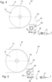
- FIG. 1 shows a section of a conveyor system 10 with a conveyor belt 12.
- a belt scraper 20 is arranged according to a first embodiment.
- the conveyed material that is on the belt 12 and partially adheres there is scraped off the belt 12 by means of the belt scraper.
- the Gurtabstreifer 20 is used as a preliminary scraper, d. H. it is located above a receiving container or a chute (not shown) for receiving the conveyed goods.
- the belt scraper 20 has a plurality of scraper blocks 22 arranged next to one another in the transverse direction.
- the stripping blocks 22 are designed as solid bodies made of plastic and are provided with a cap 24 made of hard metal at the upper end.
- the stripping blocks 22 represent stripping elements which, as in 2 shown are applied to the belt 12 so that they are in contact with the surface of the belt 12 along a surface or line-shaped contact area.
- the stripper blocks 22 are mounted on a rotatable crossbeam 26, which continues on both sides in axle elements 32, which are mounted in bearings 28 in such a way that the stripper blocks 22 are pivotably arranged together with the crossbeam 26 by rotation of the axle elements 32 about a pivot axis 30 .
- Spring devices 34 are provided on both sides of the bearings 28 for the cross member 26 and the axle elements 32 . Like in particular 3 As can be seen, these each comprise a swivel arm 36 extending straight from the swivel axis 30 and a spring rod 38 articulated at its end. The spring rod 38 and the swivel arm 36 thus apply a torque to the entire arrangement of the scraper blocks 22 on the crossbeam 26 counter to the direction of rotation of the drum 14, so that the scraper blocks 22 are pressed onto the surface of the belt 12 with a force.
- the swivel arm 36 is arranged rigidly with respect to the stripping blocks 22 and can be swiveled about the swivel axis 30 together with them.
- the pivot arm 36 is arranged opposite the stripping blocks 22 with respect to the pivot axis 30, i.e. a first direction from the pivot axis 30 to the front edge of the contact surface of the stripping blocks 22 and a second direction from the axis 30 to the pivot point of the spring rod 38
- the end of the swivel arm 36 forms an obtuse angle w.
- other arrangements can also be selected in which a different angle w results, for example an acute angle.
- the housing 40 of the spring bar is not arranged completely stationary with respect to the belt structure (not shown) of the conveyor device 10, but is as in FIG 3 shown hinged relative thereto so that it can pivot.
- the movement of the housing 40 is coupled to the movement of the stripping elements 26 via the spring rod 38, the pivoting lever 36 and the cross member 26.
- the coupling is designed in such a way that the housing 40 only performs a movement that is significantly reduced compared to a pivoting movement of the stripping element 26, namely a pivoting movement by a significantly smaller pivoting angle.
- a sensor 44 is arranged on the spring device 34, with which the angular position of the stripping blocks 22 can be determined and output as an electrical sensor signal S.
- a pivot angle a is shown as an example between a first direction from the pivot axis 30 to the front edge of the contact surface of the scraper block 22 on the belt 14 (in the original state of the scraper block 22, as shown later, the contact surface shifts with wear) and a second direction, which is shown here as Reference is shown horizontally.
- the sensor 44 detects a distance d between an index part 46 at the end of the spring rod 38 and a detection part 48 fixed at the end of the cylindrical housing 40 .
- the distance d depends directly on the angular position a of the stripping blocks 22 .
- the angle a increases.
- the distance d between the end of the rod 38 and the end of the housing 40 is thus reduced via the coupling by the pivoting lever 36 and the rod 38, and thus also the distance between the index part 46 and the detection part 48 of the sensor 44.
- the relationship between a and d is almost linear in the angular range shown where the pivot arm 36 and spring rod 38 are nearly perpendicular to each other.
- the angle a decreases and the distance d increases.
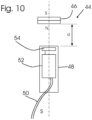
- 10 1 shows the structure of the sensor 44 schematically.
- a magnetic or magneto-inductive sensor is used in which the index part 46 is designed as a disc-shaped permanent magnet which is magnetized in the direction of the sensor's longitudinal axis.
- the detection part 48 of the sensor is arranged at a distance d from the index part 46 and comprises a magnetic field sensor element 54 in a sensor housing and an electrical detection and evaluation circuit 52 connected to it.
- the detection and evaluation circuit 52 is operated by an electrical supply via a cable connection 50.
- the permanent magnet of the index part 46 causes a different magnetic field at the location of the magnetic field sensor element 54, so that a measurable physical property of the magnetic field sensor element 54 changes.
- magnetic field sensor elements 54 can be used.
- a Hall element can be used as the magnetic field sensor element 54, the resistance of which changes as a function of the magnetic field.
- a soft magnetic material can also be used, the permeability of which changes depending on the magnetic field, e.g. as described in DE 10 2007 062 862 A1 .
- the detection and evaluation circuit 52 operates the magnetic field sensor element 54 as required for the detection of the magnetic field, evaluates its measurable properties and converts this into a sensor signal S.
- the sensor signal S is output as an electrical signal via the cable connection 50, for example as a current or voltage signal.
- the sensor signal S can be unambiguously assigned to the distance d, with the dependency within the possible pivoting range of the stripping blocks 22 preferably being at least essentially linear.
- the sensor signal S By evaluating the sensor signal S, for example, progressive wear of the stripping element, in this case the stripping blocks 22, can be determined.
- the constant contact of the scraper blocks 22 on the running belt 12 leads to abrasion, so that the angle a increases over the period of operation. This is indicated by a change in the sensor signal S, so that wear monitoring is made possible, with an indication being given when the stripper blocks 22 need to be replaced.
- the senor 44 is arranged on the scraper 20 in such a way that the self-sufficient index part 46 is attached to a part that can be moved synchronously with the pivoting movement of the scraper element 24, namely the rod 38.
- the detection part 48 is attached to an almost stationary part, the one compared to the movement of the stripping element 24 performs significantly reduced movement, namely on the housing 40 of the spring unit 34. In this way, the cable routing is facilitated, since the cable 50 only has to compensate for the slight movement of the housing 40.
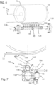
- the following is an embodiment of a scraper 120 as a comparative example in view of the illustrations Figures 6 - 9 described.
- the scraper 120 is also attached to a conveyor system 10 .
- the scraper 120 has a stationary, height-adjustable, but non-rotatable cross member (system carrier) 126 on which a plurality of scraper modules 122 are arranged next to one another.
- system carrier system carrier
- One of the stripper modules 122 is in 7 in a side view along the axis of the system carrier 126, in 8 in side view along a module pivot axis 130 and in 9 shown in front view. It comprises a hard metal lamella 124 designed for peeling contact with the belt 12, which is fastened to a blade carrier 162 which can be pivoted about the module pivot axis 130 in a joint 164. A foot 166 that carries the joint 164 is mounted in the system carrier 126 .
- the stripping module 122 is inclined at a small angle to the transverse direction, so that the module pivot axis 130 is aligned horizontally and runs essentially transverse to the running direction of the belt 12, but does not correspond exactly to the longitudinal axis of the system carrier 162.
- the cutter support 162 and the lamella 124 attached to it is as in 8 indicated in the joint 164 so as to be pivotable about the module pivot axis 130 .
- the swivel angle a can be defined, for example, as in 8 shown between a direction from the module pivot axis 130 to the front edge of the louver 124 and a horizontal.
- a torsion spring (not shown) acts within the joint 164 in such a way that the cutter carrier 162 is subjected to a torque, as a result of which the lamella 124 is pressed in the direction of contact with the belt 12 .
- a front edge of the sipe 124 rests on the surface of the belt 12 . With the belt 12 running, adhering material to be conveyed is stripped off.
- a swivel arm 136 is rigidly attached to the blade carrier 162 in such a way that it can also be swiveled about the module swivel axis 130 .
- the pivoting arm 136 is fastened as an extension of the cutter support 162, clamped in the example shown, so that pivoting of the cutter support 162 and the lamella 124 leads to the same pivoting movement of the pivoting arm 136.
- a sensor 44 is arranged to detect the pivoting angle ⁇ of the blade carrier 162 and the lamella 124 .
- Sensor 44 includes an index portion 46 attached to the end of pivot arm 136 and a sensing portion 48 attached to lead frame 126.
- the sensor 44 is the same sensor as previously with respect to FIG 10 explained, ie by means of the detection part 48 the distance d to the index part 46 is detected and as a sensor signal S output via the cable connector 50.
- the distance d is as e.g. in 8 indicated as a function of the position assumed by the blade carrier 162 and the lamella 124, ie by the angle a.
- the angle a increases in the example shown to a value a1 and thus the distance d to a larger value d1.
- the detection part 48 is attached to a stationary member, namely the lead frame 126, so that easy cable routing is ensured.
- the index part 46 is arranged on a movable element, namely on the pivot arm 136 .
- Pivot arm 136 extends with respect to module pivot axis 130 in a direction substantially opposite to blade 124, ie, a first direction from module pivot axis 130 to the front edge of blade 124 and a second direction from module pivot axis 130 to the index portion 46 at the end of the swing arm 136 form an obtuse angle.
- the joint 164 is located on the module pivot axis 130 between the end of the pivot arm 136 and the lamella 164. The sensor 44 is thus far enough away from the lamella 124 so that it is not affected by scraped conveyed material.
Landscapes
- Engineering & Computer Science (AREA)
- Mechanical Engineering (AREA)
- Physics & Mathematics (AREA)
- General Physics & Mathematics (AREA)
- Control Of Conveyors (AREA)
- Devices For Conveying Motion By Means Of Endless Flexible Members (AREA)
- Paper (AREA)
- Cleaning In General (AREA)
- Coating Apparatus (AREA)
- Compositions Of Macromolecular Compounds (AREA)
- Structure Of Belt Conveyors (AREA)
- Adhesive Tape Dispensing Devices (AREA)
Applications Claiming Priority (2)
| Application Number | Priority Date | Filing Date | Title |
|---|---|---|---|
| DE102018123799.5A DE102018123799A1 (de) | 2018-09-26 | 2018-09-26 | Gurtabstreifer und Verfahren zum Betrieb eines Gurtabstreifers |
| PCT/EP2019/074729 WO2020064405A1 (de) | 2018-09-26 | 2019-09-16 | Gurtabstreifer und verfahren zum betrieb eines gurtabstreifers |
Publications (3)
| Publication Number | Publication Date |
|---|---|
| EP3856664A1 EP3856664A1 (de) | 2021-08-04 |
| EP3856664C0 EP3856664C0 (de) | 2023-06-28 |
| EP3856664B1 true EP3856664B1 (de) | 2023-06-28 |
Family
ID=68066776
Family Applications (1)
| Application Number | Title | Priority Date | Filing Date |
|---|---|---|---|
| EP19774073.1A Active EP3856664B1 (de) | 2018-09-26 | 2019-09-16 | Gurtabstreifer und verfahren zum betrieb eines gurtabstreifers |
Country Status (17)
| Country | Link |
|---|---|
| US (1) | US11420827B2 (pl) |
| EP (1) | EP3856664B1 (pl) |
| JP (1) | JP7185770B2 (pl) |
| CN (1) | CN112823131B (pl) |
| AU (1) | AU2019348323B2 (pl) |
| CA (1) | CA3114484C (pl) |
| CL (1) | CL2021000765A1 (pl) |
| DE (1) | DE102018123799A1 (pl) |
| ES (1) | ES2958222T3 (pl) |
| MX (1) | MX2021003526A (pl) |
| PE (1) | PE20211619A1 (pl) |
| PL (1) | PL3856664T3 (pl) |
| RU (1) | RU2758220C1 (pl) |
| TW (1) | TWI791899B (pl) |
| UA (1) | UA126050C2 (pl) |
| WO (1) | WO2020064405A1 (pl) |
| ZA (1) | ZA202102737B (pl) |
Families Citing this family (11)
| Publication number | Priority date | Publication date | Assignee | Title |
|---|---|---|---|---|
| WO2019118579A2 (en) * | 2017-12-13 | 2019-06-20 | Laitram, L.L.C. | Hygienic hollow frame assembly |
| PE20250461A1 (es) * | 2017-12-22 | 2025-02-21 | Flexible Steel Lacing Co | Aparato y metodo para monitorear sistemas transportadores |
| RU204009U1 (ru) * | 2020-04-05 | 2021-05-04 | Алексей Валерьевич Аристов | Флажок для бесконтактного индуктивного датчика |
| ES2979308T3 (es) * | 2020-11-27 | 2024-09-25 | Kill Frech Cornelia | Sistema rascador de cinta de transporte de fácil mantenimiento |
| EP4504626A4 (en) * | 2022-04-01 | 2026-03-11 | Flexible Steel Lacing Co | Conveyor Belt Cleaning Device Scraper Blade Mounting Block |
| CN114800808A (zh) * | 2022-04-21 | 2022-07-29 | 广东博智林机器人有限公司 | 刮刀设备 |
| ES3064595T3 (en) * | 2022-10-11 | 2026-04-27 | Schulte Strathaus Gmbh & Co Kg Foerdertechnik Dichtungssysteme | System and method for monitoring the state of a conveyor belt of a conveyor-belt installation, and a corresponding conveyor-belt installation |
| CN116424811B (zh) * | 2023-02-24 | 2023-10-27 | 江苏伊凡诺尔智能科技有限公司 | 一种带式输送机的皮带附着物清理装置 |
| CN116753820B (zh) * | 2023-08-16 | 2023-11-14 | 枣庄金大包装有限公司 | 一种凹版印刷机刮墨刀的角度测量尺 |
| CN118751530A (zh) * | 2024-06-05 | 2024-10-11 | 安迈特科技(北京)有限公司 | 凸点筛选设备及其凸点筛选方法 |
| CN120534718B (zh) * | 2025-07-23 | 2025-10-10 | 常州市惠昌传感器有限公司 | 一种传感器全自动组装用测试机 |
Family Cites Families (22)
| Publication number | Priority date | Publication date | Assignee | Title |
|---|---|---|---|---|
| US4269301A (en) * | 1979-10-22 | 1981-05-26 | Gibbs Alfred S | Conveyor belt scraper system |
| JPS60106710A (ja) * | 1983-11-15 | 1985-06-12 | Nippon Tsusho Kk | 遠隔監視型ベルトクリ−ナ装置 |
| US4768645A (en) * | 1987-02-20 | 1988-09-06 | Farris Sammy D | Conveyor belt scraping apparatus |
| JPH0237121U (pl) * | 1988-09-02 | 1990-03-12 | ||
| US5248026A (en) * | 1992-07-22 | 1993-09-28 | Morefield Allen J | Conveyor belt scraper mechanisms |
| GB9221426D0 (en) * | 1992-10-13 | 1992-11-25 | Morin Normand J | Conveyor belt scraper |
| CA2245011A1 (en) * | 1996-12-02 | 1998-06-11 | Asgco Manufacturing, Inc. | Self-indicating tensioner for a belt scraper |
| US6986418B2 (en) * | 1998-12-10 | 2006-01-17 | Martin Engineering Company | Conveyor belt cleaner scraper blade with sensor and control system therefor |
| DE60013937T3 (de) * | 1999-03-17 | 2008-08-21 | Martin Engineering Co., Neponset | Förderbandreiniger und -spannvorrichtung |
| DE19926184A1 (de) * | 1999-06-09 | 2000-12-14 | Schwarze Hans Otto | Bandfördervorrrichtung o. dgl. |
| JP2003112129A (ja) * | 2001-10-05 | 2003-04-15 | Fuji Xerox Co Ltd | クリーニング装置および画像形成装置 |
| FI113039B (fi) * | 2001-10-26 | 2004-02-27 | Roxon Oy | Hihnakuljetin ja puhdistinlaite |
| DE10246573B4 (de) * | 2002-10-05 | 2005-08-11 | Dr.Ing.H.C. F. Porsche Ag | Messeinrichtung und Verfahren zur berührungslosen Positionsermittlung |
| DE102004014084A1 (de) | 2003-03-20 | 2004-10-21 | Hanse-Chemie Handelsgesellschaft mbH für Chemie und Kunststoffprodukte | Vorrichtung zur Überwachung einer Fördergurtanordnung mit einem Gurtreiniger |
| DE102007062862A1 (de) * | 2006-12-21 | 2008-07-10 | Micro-Epsilon Messtechnik Gmbh & Co. Kg | Verfahren und Sensoranordnung zum Bestimmen der Position und/oder Positionsänderung eines Messobjekts relativ zu einem Sensor |
| DE102010002109A1 (de) | 2010-02-18 | 2011-08-18 | ZF Friedrichshafen AG, 88046 | Sensoranordnung |
| US8205741B2 (en) * | 2010-08-06 | 2012-06-26 | Martin Engineering Company | Method of adjusting conveyor belt scrapers and open loop control system for conveyor belt scrapers |
| DE102013006821B4 (de) | 2013-01-07 | 2016-05-04 | Hans-Otto Schwarze | Gurtabstreifer mit Winkelhöhenverstellung |
| DE102014006281A1 (de) * | 2014-05-02 | 2015-11-05 | Hans-Otto Schwarze | Gurtabstreifer mit Modulschrägstellung |
| DE202014007229U1 (de) | 2014-08-11 | 2015-07-01 | F.E. Schulte Strathaus GmbH & Co. KG Fördertechnik Dichtungssysteme | Förderband-Abstreifvorrichtung |
| TW201825370A (zh) | 2017-01-09 | 2018-07-16 | 漢斯 奧托 施瓦茨 | 帶輸送器之刮拭器及清潔快速運行之輸送帶之方法 |
| PE20250461A1 (es) | 2017-12-22 | 2025-02-21 | Flexible Steel Lacing Co | Aparato y metodo para monitorear sistemas transportadores |
-
2018
- 2018-09-26 DE DE102018123799.5A patent/DE102018123799A1/de not_active Withdrawn
-
2019
- 2019-09-16 MX MX2021003526A patent/MX2021003526A/es unknown
- 2019-09-16 CN CN201980062784.1A patent/CN112823131B/zh active Active
- 2019-09-16 AU AU2019348323A patent/AU2019348323B2/en active Active
- 2019-09-16 JP JP2021514389A patent/JP7185770B2/ja active Active
- 2019-09-16 CA CA3114484A patent/CA3114484C/en active Active
- 2019-09-16 US US17/279,997 patent/US11420827B2/en active Active
- 2019-09-16 RU RU2021111583A patent/RU2758220C1/ru active
- 2019-09-16 PE PE2021000311A patent/PE20211619A1/es unknown
- 2019-09-16 WO PCT/EP2019/074729 patent/WO2020064405A1/de not_active Ceased
- 2019-09-16 EP EP19774073.1A patent/EP3856664B1/de active Active
- 2019-09-16 ES ES19774073T patent/ES2958222T3/es active Active
- 2019-09-16 PL PL19774073.1T patent/PL3856664T3/pl unknown
- 2019-09-16 UA UAA202101577A patent/UA126050C2/uk unknown
- 2019-09-25 TW TW108134603A patent/TWI791899B/zh active
-
2021
- 2021-03-26 CL CL2021000765A patent/CL2021000765A1/es unknown
- 2021-04-23 ZA ZA2021/02737A patent/ZA202102737B/en unknown
Also Published As
| Publication number | Publication date |
|---|---|
| JP7185770B2 (ja) | 2022-12-07 |
| MX2021003526A (es) | 2021-05-27 |
| BR112021005736A2 (pt) | 2021-06-29 |
| DE102018123799A1 (de) | 2020-03-26 |
| EP3856664C0 (de) | 2023-06-28 |
| CA3114484C (en) | 2024-01-02 |
| AU2019348323A1 (en) | 2021-04-15 |
| US20220033192A1 (en) | 2022-02-03 |
| ZA202102737B (en) | 2022-10-26 |
| US11420827B2 (en) | 2022-08-23 |
| CN112823131A (zh) | 2021-05-18 |
| PE20211619A1 (es) | 2021-08-23 |
| PL3856664T3 (pl) | 2023-11-27 |
| AU2019348323B2 (en) | 2022-08-11 |
| UA126050C2 (uk) | 2022-08-03 |
| CA3114484A1 (en) | 2020-04-02 |
| CL2021000765A1 (es) | 2021-09-10 |
| TW202019568A (zh) | 2020-06-01 |
| RU2758220C1 (ru) | 2021-10-26 |
| EP3856664A1 (de) | 2021-08-04 |
| WO2020064405A1 (de) | 2020-04-02 |
| CN112823131B (zh) | 2022-08-23 |
| TWI791899B (zh) | 2023-02-11 |
| JP2022501286A (ja) | 2022-01-06 |
| ES2958222T3 (es) | 2024-02-05 |
Similar Documents
| Publication | Publication Date | Title |
|---|---|---|
| EP3856664A1 (de) | Gurtabstreifer und verfahren zum betrieb eines gurtabstreifers | |
| EP2683561B1 (de) | Verschleisserkennungssystem und verfahren | |
| EP3840968B1 (de) | Wankstabilisator | |
| EP2711132A1 (de) | Messvorrichtung | |
| EP2243671B1 (de) | Wischerblatt und Scheibenwischersystem | |
| EP2096433A1 (de) | Vorrichtung zur zerstörungsfreien Materialprüfung eines Prüfgegenstands mit Ultraschallwellen | |
| EP3573855A1 (de) | VORRICHTUNG UND VERFAHREN ZUR ERKENNUNG DES VERSCHLEIßES EINES SCHLEIFKONTAKTES UND SCHLEIFLEITUNGSSYSTEM | |
| DE202017105655U1 (de) | Vorrichtung zur automatischen Korrektur der Positionsabweichung von Förderbändern | |
| DE102008030773B4 (de) | Anordnung zur Integration einer Messelektronik in Crimpzangen | |
| EP2887040B1 (de) | Vorrichtung und Verfahren zum Ermitteln der Kontaktkraft zwischen zwei Bauteilen | |
| DE10251983A1 (de) | Schaberklingenhaltevorrichtung | |
| EP2356047A1 (de) | Segmentkörper und abstreifer für einen fördergurtabstreifer | |
| EP3513159B1 (de) | Vorrichtung und verfahren zur anbringung eines ausgleichsgewichts an einer befestigungsfläche an einer innenseite einer felge | |
| EP3331340A1 (de) | Dreipunktaufhängung | |
| DE69632946T2 (de) | Vorrichtung zur Messung der relativen Drehung und/oder Drehgeschwindigkeit zwischen den Laufringen eines Wälzlagers | |
| WO2022063518A1 (de) | BREMSZANGENEINHEIT MIT EINER VERSCHLEIßSENSORVORRICHTUNG, UND VERFAHREN ZUM ERFASSEN VON VERSCHLEIß VON BREMSBELÄGEN UND BREMSSCHEIBE EINER BREMSZANGENEINHEIT | |
| EP4416087B1 (de) | System und verfahren zur überwachung des zustands eines förderbands einer förderbandanlage sowie eine entsprechende förderbandanlage | |
| DE102008000472A1 (de) | Radaufhängung für ein Fahrzeug | |
| DE10105781A1 (de) | Einrichtung zur Erfassung und Verfahren zur Auswertung von Geometrieveränderungen an rotierenden Objekten | |
| EP1795881B1 (de) | Verfahren und Vorrichtung zur Abschätzung des Betriebszustandes eines Fahrzeugreifens | |
| DE102018114154A1 (de) | Vorrichtung zum Transportieren von Behältern in einer Reinigungsmaschine | |
| DE102007055189A1 (de) | Kapazitive Messeinrichtung mit einem zwischen Elektrodenplatten angeordnetem Element mit Abschnitten unterschiedlicher Dielektrizitätskonstanten | |
| EP0864472B1 (de) | Antriebsvorrichtung, insbesondere für Scheibenwischer an Kraftfahrzeugen | |
| DE19532376C1 (de) | Vorrichtung zum Abstreifen von Fremdkörpern von der Lauffläche eines vor- und rückwärts drehbaren Fahrzeugrades | |
| DE102019126209A1 (de) | Rolle oder Trommel mit Drucksensoren |
Legal Events
| Date | Code | Title | Description |
|---|---|---|---|
| STAA | Information on the status of an ep patent application or granted ep patent |
Free format text: STATUS: UNKNOWN |
|
| STAA | Information on the status of an ep patent application or granted ep patent |
Free format text: STATUS: THE INTERNATIONAL PUBLICATION HAS BEEN MADE |
|
| PUAI | Public reference made under article 153(3) epc to a published international application that has entered the european phase |
Free format text: ORIGINAL CODE: 0009012 |
|
| STAA | Information on the status of an ep patent application or granted ep patent |
Free format text: STATUS: REQUEST FOR EXAMINATION WAS MADE |
|
| 17P | Request for examination filed |
Effective date: 20210421 |
|
| AK | Designated contracting states |
Kind code of ref document: A1 Designated state(s): AL AT BE BG CH CY CZ DE DK EE ES FI FR GB GR HR HU IE IS IT LI LT LU LV MC MK MT NL NO PL PT RO RS SE SI SK SM TR |
|
| DAV | Request for validation of the european patent (deleted) | ||
| DAX | Request for extension of the european patent (deleted) | ||
| GRAP | Despatch of communication of intention to grant a patent |
Free format text: ORIGINAL CODE: EPIDOSNIGR1 |
|
| STAA | Information on the status of an ep patent application or granted ep patent |
Free format text: STATUS: GRANT OF PATENT IS INTENDED |
|
| RIC1 | Information provided on ipc code assigned before grant |
Ipc: G01B 7/30 20060101ALI20221130BHEP Ipc: G01B 5/24 20060101ALI20221130BHEP Ipc: B65G 45/12 20060101AFI20221130BHEP |
|
| INTG | Intention to grant announced |
Effective date: 20221221 |
|
| GRAJ | Information related to disapproval of communication of intention to grant by the applicant or resumption of examination proceedings by the epo deleted |
Free format text: ORIGINAL CODE: EPIDOSDIGR1 |
|
| STAA | Information on the status of an ep patent application or granted ep patent |
Free format text: STATUS: REQUEST FOR EXAMINATION WAS MADE |
|
| GRAP | Despatch of communication of intention to grant a patent |
Free format text: ORIGINAL CODE: EPIDOSNIGR1 |
|
| STAA | Information on the status of an ep patent application or granted ep patent |
Free format text: STATUS: GRANT OF PATENT IS INTENDED |
|
| INTC | Intention to grant announced (deleted) | ||
| INTG | Intention to grant announced |
Effective date: 20230303 |
|
| GRAS | Grant fee paid |
Free format text: ORIGINAL CODE: EPIDOSNIGR3 |
|
| RAP1 | Party data changed (applicant data changed or rights of an application transferred) |
Owner name: KILL-FRECH, CORNELIA |
|
| GRAA | (expected) grant |
Free format text: ORIGINAL CODE: 0009210 |
|
| STAA | Information on the status of an ep patent application or granted ep patent |
Free format text: STATUS: THE PATENT HAS BEEN GRANTED |
|
| AK | Designated contracting states |
Kind code of ref document: B1 Designated state(s): AL AT BE BG CH CY CZ DE DK EE ES FI FR GB GR HR HU IE IS IT LI LT LU LV MC MK MT NL NO PL PT RO RS SE SI SK SM TR |
|
| REG | Reference to a national code |
Ref country code: CH Ref legal event code: EP |
|
| REG | Reference to a national code |
Ref country code: AT Ref legal event code: REF Ref document number: 1582539 Country of ref document: AT Kind code of ref document: T Effective date: 20230715 |
|
| REG | Reference to a national code |
Ref country code: IE Ref legal event code: FG4D Free format text: LANGUAGE OF EP DOCUMENT: GERMAN |
|
| REG | Reference to a national code |
Ref country code: DE Ref legal event code: R096 Ref document number: 502019008350 Country of ref document: DE |
|
| U01 | Request for unitary effect filed |
Effective date: 20230628 |
|
| U07 | Unitary effect registered |
Designated state(s): AT BE BG DE DK EE FI FR IT LT LU LV MT NL PT SE SI Effective date: 20230703 |
|
| REG | Reference to a national code |
Ref country code: RO Ref legal event code: EPE |
|
| REG | Reference to a national code |
Ref country code: LT Ref legal event code: MG9D |
|
| PG25 | Lapsed in a contracting state [announced via postgrant information from national office to epo] |
Ref country code: NO Free format text: LAPSE BECAUSE OF FAILURE TO SUBMIT A TRANSLATION OF THE DESCRIPTION OR TO PAY THE FEE WITHIN THE PRESCRIBED TIME-LIMIT Effective date: 20230928 |
|
| U20 | Renewal fee for the european patent with unitary effect paid |
Year of fee payment: 5 Effective date: 20230926 |
|
| PG25 | Lapsed in a contracting state [announced via postgrant information from national office to epo] |
Ref country code: RS Free format text: LAPSE BECAUSE OF FAILURE TO SUBMIT A TRANSLATION OF THE DESCRIPTION OR TO PAY THE FEE WITHIN THE PRESCRIBED TIME-LIMIT Effective date: 20230628 Ref country code: HR Free format text: LAPSE BECAUSE OF FAILURE TO SUBMIT A TRANSLATION OF THE DESCRIPTION OR TO PAY THE FEE WITHIN THE PRESCRIBED TIME-LIMIT Effective date: 20230628 Ref country code: GR Free format text: LAPSE BECAUSE OF FAILURE TO SUBMIT A TRANSLATION OF THE DESCRIPTION OR TO PAY THE FEE WITHIN THE PRESCRIBED TIME-LIMIT Effective date: 20230929 |
|
| PG25 | Lapsed in a contracting state [announced via postgrant information from national office to epo] |
Ref country code: SK Free format text: LAPSE BECAUSE OF FAILURE TO SUBMIT A TRANSLATION OF THE DESCRIPTION OR TO PAY THE FEE WITHIN THE PRESCRIBED TIME-LIMIT Effective date: 20230628 |
|
| PG25 | Lapsed in a contracting state [announced via postgrant information from national office to epo] |
Ref country code: IS Free format text: LAPSE BECAUSE OF FAILURE TO SUBMIT A TRANSLATION OF THE DESCRIPTION OR TO PAY THE FEE WITHIN THE PRESCRIBED TIME-LIMIT Effective date: 20231028 |
|
| PG25 | Lapsed in a contracting state [announced via postgrant information from national office to epo] |
Ref country code: SM Free format text: LAPSE BECAUSE OF FAILURE TO SUBMIT A TRANSLATION OF THE DESCRIPTION OR TO PAY THE FEE WITHIN THE PRESCRIBED TIME-LIMIT Effective date: 20230628 Ref country code: SK Free format text: LAPSE BECAUSE OF FAILURE TO SUBMIT A TRANSLATION OF THE DESCRIPTION OR TO PAY THE FEE WITHIN THE PRESCRIBED TIME-LIMIT Effective date: 20230628 Ref country code: IS Free format text: LAPSE BECAUSE OF FAILURE TO SUBMIT A TRANSLATION OF THE DESCRIPTION OR TO PAY THE FEE WITHIN THE PRESCRIBED TIME-LIMIT Effective date: 20231028 Ref country code: CZ Free format text: LAPSE BECAUSE OF FAILURE TO SUBMIT A TRANSLATION OF THE DESCRIPTION OR TO PAY THE FEE WITHIN THE PRESCRIBED TIME-LIMIT Effective date: 20230628 |
|
| REG | Reference to a national code |
Ref country code: DE Ref legal event code: R097 Ref document number: 502019008350 Country of ref document: DE |
|
| PLBE | No opposition filed within time limit |
Free format text: ORIGINAL CODE: 0009261 |
|
| STAA | Information on the status of an ep patent application or granted ep patent |
Free format text: STATUS: NO OPPOSITION FILED WITHIN TIME LIMIT |
|
| PG25 | Lapsed in a contracting state [announced via postgrant information from national office to epo] |
Ref country code: MC Free format text: LAPSE BECAUSE OF FAILURE TO SUBMIT A TRANSLATION OF THE DESCRIPTION OR TO PAY THE FEE WITHIN THE PRESCRIBED TIME-LIMIT Effective date: 20230628 |
|
| 26N | No opposition filed |
Effective date: 20240402 |
|
| REG | Reference to a national code |
Ref country code: IE Ref legal event code: MM4A |
|
| PG25 | Lapsed in a contracting state [announced via postgrant information from national office to epo] |
Ref country code: IE Free format text: LAPSE BECAUSE OF NON-PAYMENT OF DUE FEES Effective date: 20230916 |
|
| PG25 | Lapsed in a contracting state [announced via postgrant information from national office to epo] |
Ref country code: IE Free format text: LAPSE BECAUSE OF NON-PAYMENT OF DUE FEES Effective date: 20230916 |
|
| U20 | Renewal fee for the european patent with unitary effect paid |
Year of fee payment: 6 Effective date: 20240925 |
|
| PG25 | Lapsed in a contracting state [announced via postgrant information from national office to epo] |
Ref country code: CY Free format text: LAPSE BECAUSE OF FAILURE TO SUBMIT A TRANSLATION OF THE DESCRIPTION OR TO PAY THE FEE WITHIN THE PRESCRIBED TIME-LIMIT; INVALID AB INITIO Effective date: 20190916 |
|
| PG25 | Lapsed in a contracting state [announced via postgrant information from national office to epo] |
Ref country code: HU Free format text: LAPSE BECAUSE OF FAILURE TO SUBMIT A TRANSLATION OF THE DESCRIPTION OR TO PAY THE FEE WITHIN THE PRESCRIBED TIME-LIMIT; INVALID AB INITIO Effective date: 20190916 |
|
| REG | Reference to a national code |
Ref country code: CH Ref legal event code: U11 Free format text: ST27 STATUS EVENT CODE: U-0-0-U10-U11 (AS PROVIDED BY THE NATIONAL OFFICE) Effective date: 20251001 |
|
| PGFP | Annual fee paid to national office [announced via postgrant information from national office to epo] |
Ref country code: PL Payment date: 20250814 Year of fee payment: 7 |
|
| PGFP | Annual fee paid to national office [announced via postgrant information from national office to epo] |
Ref country code: GB Payment date: 20250923 Year of fee payment: 7 |
|
| PGFP | Annual fee paid to national office [announced via postgrant information from national office to epo] |
Ref country code: RO Payment date: 20250909 Year of fee payment: 7 |
|
| U20 | Renewal fee for the european patent with unitary effect paid |
Year of fee payment: 7 Effective date: 20250923 |
|
| PG25 | Lapsed in a contracting state [announced via postgrant information from national office to epo] |
Ref country code: TR Free format text: LAPSE BECAUSE OF FAILURE TO SUBMIT A TRANSLATION OF THE DESCRIPTION OR TO PAY THE FEE WITHIN THE PRESCRIBED TIME-LIMIT Effective date: 20230628 |
|
| PGFP | Annual fee paid to national office [announced via postgrant information from national office to epo] |
Ref country code: CH Payment date: 20251001 Year of fee payment: 7 |
|
| PGFP | Annual fee paid to national office [announced via postgrant information from national office to epo] |
Ref country code: ES Payment date: 20251020 Year of fee payment: 7 |