EP3854894A1 - Procédé de fusion de minerai d'oxyde - Google Patents
Procédé de fusion de minerai d'oxyde Download PDFInfo
- Publication number
- EP3854894A1 EP3854894A1 EP19862577.4A EP19862577A EP3854894A1 EP 3854894 A1 EP3854894 A1 EP 3854894A1 EP 19862577 A EP19862577 A EP 19862577A EP 3854894 A1 EP3854894 A1 EP 3854894A1
- Authority
- EP
- European Patent Office
- Prior art keywords
- reducing
- mixture
- oxide ore
- metal
- furnace
- Prior art date
- Legal status (The legal status is an assumption and is not a legal conclusion. Google has not performed a legal analysis and makes no representation as to the accuracy of the status listed.)
- Granted
Links
- 238000000034 method Methods 0.000 title claims abstract description 57
- 238000003723 Smelting Methods 0.000 title claims abstract description 46
- 230000001603 reducing effect Effects 0.000 claims abstract description 138
- 239000000203 mixture Substances 0.000 claims abstract description 125
- 239000002184 metal Substances 0.000 claims abstract description 124
- 229910052751 metal Inorganic materials 0.000 claims abstract description 124
- 230000009467 reduction Effects 0.000 claims abstract description 101
- 239000002893 slag Substances 0.000 claims abstract description 58
- 229910000480 nickel oxide Inorganic materials 0.000 claims abstract description 54
- GNRSAWUEBMWBQH-UHFFFAOYSA-N oxonickel Chemical compound [Ni]=O GNRSAWUEBMWBQH-UHFFFAOYSA-N 0.000 claims abstract description 52
- 239000003638 chemical reducing agent Substances 0.000 claims abstract description 30
- 238000010438 heat treatment Methods 0.000 claims abstract description 29
- 230000005484 gravity Effects 0.000 claims abstract description 17
- 229910000863 Ferronickel Inorganic materials 0.000 claims abstract description 15
- 238000004519 manufacturing process Methods 0.000 claims abstract description 9
- 238000011282 treatment Methods 0.000 claims description 143
- 238000001035 drying Methods 0.000 claims description 99
- 239000000446 fuel Substances 0.000 claims description 16
- 238000000926 separation method Methods 0.000 abstract 1
- 238000006722 reduction reaction Methods 0.000 description 111
- PXHVJJICTQNCMI-UHFFFAOYSA-N Nickel Chemical compound [Ni] PXHVJJICTQNCMI-UHFFFAOYSA-N 0.000 description 78
- 239000007789 gas Substances 0.000 description 42
- 238000002156 mixing Methods 0.000 description 36
- 229910052759 nickel Inorganic materials 0.000 description 36
- XEEYBQQBJWHFJM-UHFFFAOYSA-N Iron Chemical compound [Fe] XEEYBQQBJWHFJM-UHFFFAOYSA-N 0.000 description 24
- 239000002994 raw material Substances 0.000 description 22
- UQSXHKLRYXJYBZ-UHFFFAOYSA-N Iron oxide Chemical compound [Fe]=O UQSXHKLRYXJYBZ-UHFFFAOYSA-N 0.000 description 14
- 230000000052 comparative effect Effects 0.000 description 11
- 229910052742 iron Inorganic materials 0.000 description 11
- 238000011084 recovery Methods 0.000 description 11
- 239000008188 pellet Substances 0.000 description 10
- 239000000843 powder Substances 0.000 description 10
- 238000007599 discharging Methods 0.000 description 9
- 230000001276 controlling effect Effects 0.000 description 8
- VYPSYNLAJGMNEJ-UHFFFAOYSA-N Silicium dioxide Chemical compound O=[Si]=O VYPSYNLAJGMNEJ-UHFFFAOYSA-N 0.000 description 7
- 239000007787 solid Substances 0.000 description 7
- 239000003245 coal Substances 0.000 description 6
- 238000010586 diagram Methods 0.000 description 6
- 238000012423 maintenance Methods 0.000 description 6
- 239000011230 binding agent Substances 0.000 description 5
- 238000006243 chemical reaction Methods 0.000 description 5
- 239000002245 particle Substances 0.000 description 5
- 239000000126 substance Substances 0.000 description 5
- 230000003247 decreasing effect Effects 0.000 description 4
- 230000007812 deficiency Effects 0.000 description 4
- 229910044991 metal oxide Inorganic materials 0.000 description 4
- 150000004706 metal oxides Chemical class 0.000 description 4
- 230000003647 oxidation Effects 0.000 description 4
- 238000007254 oxidation reaction Methods 0.000 description 4
- 239000000571 coke Substances 0.000 description 3
- 230000007423 decrease Effects 0.000 description 3
- 230000004907 flux Effects 0.000 description 3
- 238000004898 kneading Methods 0.000 description 3
- 239000007788 liquid Substances 0.000 description 3
- 238000007885 magnetic separation Methods 0.000 description 3
- 238000002844 melting Methods 0.000 description 3
- 230000008018 melting Effects 0.000 description 3
- 238000010298 pulverizing process Methods 0.000 description 3
- XLYOFNOQVPJJNP-UHFFFAOYSA-N water Substances O XLYOFNOQVPJJNP-UHFFFAOYSA-N 0.000 description 3
- VZSRBBMJRBPUNF-UHFFFAOYSA-N 2-(2,3-dihydro-1H-inden-2-ylamino)-N-[3-oxo-3-(2,4,6,7-tetrahydrotriazolo[4,5-c]pyridin-5-yl)propyl]pyrimidine-5-carboxamide Chemical compound C1C(CC2=CC=CC=C12)NC1=NC=C(C=N1)C(=O)NCCC(N1CC2=C(CC1)NN=N2)=O VZSRBBMJRBPUNF-UHFFFAOYSA-N 0.000 description 2
- VTYYLEPIZMXCLO-UHFFFAOYSA-L Calcium carbonate Chemical compound [Ca+2].[O-]C([O-])=O VTYYLEPIZMXCLO-UHFFFAOYSA-L 0.000 description 2
- OKTJSMMVPCPJKN-UHFFFAOYSA-N Carbon Chemical compound [C] OKTJSMMVPCPJKN-UHFFFAOYSA-N 0.000 description 2
- 229910000640 Fe alloy Inorganic materials 0.000 description 2
- CWYNVVGOOAEACU-UHFFFAOYSA-N Fe2+ Chemical compound [Fe+2] CWYNVVGOOAEACU-UHFFFAOYSA-N 0.000 description 2
- MKYBYDHXWVHEJW-UHFFFAOYSA-N N-[1-oxo-1-(2,4,6,7-tetrahydrotriazolo[4,5-c]pyridin-5-yl)propan-2-yl]-2-[[3-(trifluoromethoxy)phenyl]methylamino]pyrimidine-5-carboxamide Chemical compound O=C(C(C)NC(=O)C=1C=NC(=NC=1)NCC1=CC(=CC=C1)OC(F)(F)F)N1CC2=C(CC1)NN=N2 MKYBYDHXWVHEJW-UHFFFAOYSA-N 0.000 description 2
- NIPNSKYNPDTRPC-UHFFFAOYSA-N N-[2-oxo-2-(2,4,6,7-tetrahydrotriazolo[4,5-c]pyridin-5-yl)ethyl]-2-[[3-(trifluoromethoxy)phenyl]methylamino]pyrimidine-5-carboxamide Chemical compound O=C(CNC(=O)C=1C=NC(=NC=1)NCC1=CC(=CC=C1)OC(F)(F)F)N1CC2=C(CC1)NN=N2 NIPNSKYNPDTRPC-UHFFFAOYSA-N 0.000 description 2
- AFCARXCZXQIEQB-UHFFFAOYSA-N N-[3-oxo-3-(2,4,6,7-tetrahydrotriazolo[4,5-c]pyridin-5-yl)propyl]-2-[[3-(trifluoromethoxy)phenyl]methylamino]pyrimidine-5-carboxamide Chemical compound O=C(CCNC(=O)C=1C=NC(=NC=1)NCC1=CC(=CC=C1)OC(F)(F)F)N1CC2=C(CC1)NN=N2 AFCARXCZXQIEQB-UHFFFAOYSA-N 0.000 description 2
- 229910000990 Ni alloy Inorganic materials 0.000 description 2
- 239000000654 additive Substances 0.000 description 2
- QVGXLLKOCUKJST-UHFFFAOYSA-N atomic oxygen Chemical compound [O] QVGXLLKOCUKJST-UHFFFAOYSA-N 0.000 description 2
- ODINCKMPIJJUCX-UHFFFAOYSA-N calcium oxide Inorganic materials [Ca]=O ODINCKMPIJJUCX-UHFFFAOYSA-N 0.000 description 2
- 239000000292 calcium oxide Substances 0.000 description 2
- 239000011248 coating agent Substances 0.000 description 2
- 238000000576 coating method Methods 0.000 description 2
- 230000005611 electricity Effects 0.000 description 2
- 230000002349 favourable effect Effects 0.000 description 2
- 239000000295 fuel oil Substances 0.000 description 2
- 229910052760 oxygen Inorganic materials 0.000 description 2
- 239000001301 oxygen Substances 0.000 description 2
- 238000010248 power generation Methods 0.000 description 2
- 239000000377 silicon dioxide Substances 0.000 description 2
- 235000012239 silicon dioxide Nutrition 0.000 description 2
- YLZOPXRUQYQQID-UHFFFAOYSA-N 3-(2,4,6,7-tetrahydrotriazolo[4,5-c]pyridin-5-yl)-1-[4-[2-[[3-(trifluoromethoxy)phenyl]methylamino]pyrimidin-5-yl]piperazin-1-yl]propan-1-one Chemical compound N1N=NC=2CN(CCC=21)CCC(=O)N1CCN(CC1)C=1C=NC(=NC=1)NCC1=CC(=CC=C1)OC(F)(F)F YLZOPXRUQYQQID-UHFFFAOYSA-N 0.000 description 1
- DEXFNLNNUZKHNO-UHFFFAOYSA-N 6-[3-[4-[2-(2,3-dihydro-1H-inden-2-ylamino)pyrimidin-5-yl]piperidin-1-yl]-3-oxopropyl]-3H-1,3-benzoxazol-2-one Chemical compound C1C(CC2=CC=CC=C12)NC1=NC=C(C=N1)C1CCN(CC1)C(CCC1=CC2=C(NC(O2)=O)C=C1)=O DEXFNLNNUZKHNO-UHFFFAOYSA-N 0.000 description 1
- 239000004484 Briquette Substances 0.000 description 1
- 229910001030 Iron–nickel alloy Inorganic materials 0.000 description 1
- 235000019738 Limestone Nutrition 0.000 description 1
- UCKMPCXJQFINFW-UHFFFAOYSA-N Sulphide Chemical compound [S-2] UCKMPCXJQFINFW-UHFFFAOYSA-N 0.000 description 1
- 239000002253 acid Substances 0.000 description 1
- 230000000996 additive effect Effects 0.000 description 1
- 230000002776 aggregation Effects 0.000 description 1
- 238000004220 aggregation Methods 0.000 description 1
- PNEYBMLMFCGWSK-UHFFFAOYSA-N aluminium oxide Inorganic materials [O-2].[O-2].[O-2].[Al+3].[Al+3] PNEYBMLMFCGWSK-UHFFFAOYSA-N 0.000 description 1
- 230000008901 benefit Effects 0.000 description 1
- 239000000440 bentonite Substances 0.000 description 1
- 229910000278 bentonite Inorganic materials 0.000 description 1
- SVPXDRXYRYOSEX-UHFFFAOYSA-N bentoquatam Chemical compound O.O=[Si]=O.O=[Al]O[Al]=O SVPXDRXYRYOSEX-UHFFFAOYSA-N 0.000 description 1
- 229910000019 calcium carbonate Inorganic materials 0.000 description 1
- AXCZMVOFGPJBDE-UHFFFAOYSA-L calcium dihydroxide Chemical compound [OH-].[OH-].[Ca+2] AXCZMVOFGPJBDE-UHFFFAOYSA-L 0.000 description 1
- 239000000920 calcium hydroxide Substances 0.000 description 1
- 229910001861 calcium hydroxide Inorganic materials 0.000 description 1
- BRPQOXSCLDDYGP-UHFFFAOYSA-N calcium oxide Chemical compound [O-2].[Ca+2] BRPQOXSCLDDYGP-UHFFFAOYSA-N 0.000 description 1
- 229910052799 carbon Inorganic materials 0.000 description 1
- 229910017052 cobalt Inorganic materials 0.000 description 1
- 239000010941 cobalt Substances 0.000 description 1
- GUTLYIVDDKVIGB-UHFFFAOYSA-N cobalt atom Chemical compound [Co] GUTLYIVDDKVIGB-UHFFFAOYSA-N 0.000 description 1
- 229910052681 coesite Inorganic materials 0.000 description 1
- 238000002485 combustion reaction Methods 0.000 description 1
- 238000007796 conventional method Methods 0.000 description 1
- 229910052593 corundum Inorganic materials 0.000 description 1
- 229910052906 cristobalite Inorganic materials 0.000 description 1
- 239000000428 dust Substances 0.000 description 1
- 230000000694 effects Effects 0.000 description 1
- -1 for example Substances 0.000 description 1
- 150000004676 glycans Chemical class 0.000 description 1
- 229910052595 hematite Inorganic materials 0.000 description 1
- 239000011019 hematite Substances 0.000 description 1
- 238000009854 hydrometallurgy Methods 0.000 description 1
- 238000011835 investigation Methods 0.000 description 1
- LIKBJVNGSGBSGK-UHFFFAOYSA-N iron(3+);oxygen(2-) Chemical compound [O-2].[O-2].[O-2].[Fe+3].[Fe+3] LIKBJVNGSGBSGK-UHFFFAOYSA-N 0.000 description 1
- 238000002386 leaching Methods 0.000 description 1
- 239000006028 limestone Substances 0.000 description 1
- 238000012986 modification Methods 0.000 description 1
- 230000004048 modification Effects 0.000 description 1
- 230000000737 periodic effect Effects 0.000 description 1
- 230000035699 permeability Effects 0.000 description 1
- 229920001282 polysaccharide Polymers 0.000 description 1
- 239000005017 polysaccharide Substances 0.000 description 1
- 235000019353 potassium silicate Nutrition 0.000 description 1
- 230000008569 process Effects 0.000 description 1
- 239000010453 quartz Substances 0.000 description 1
- 230000001105 regulatory effect Effects 0.000 description 1
- 239000011347 resin Substances 0.000 description 1
- 229920005989 resin Polymers 0.000 description 1
- NTHWMYGWWRZVTN-UHFFFAOYSA-N sodium silicate Chemical compound [Na+].[Na+].[O-][Si]([O-])=O NTHWMYGWWRZVTN-UHFFFAOYSA-N 0.000 description 1
- 239000004449 solid propellant Substances 0.000 description 1
- 229910052682 stishovite Inorganic materials 0.000 description 1
- 229910052905 tridymite Inorganic materials 0.000 description 1
- 229910001845 yogo sapphire Inorganic materials 0.000 description 1
Images
Classifications
-
- C—CHEMISTRY; METALLURGY
- C22—METALLURGY; FERROUS OR NON-FERROUS ALLOYS; TREATMENT OF ALLOYS OR NON-FERROUS METALS
- C22C—ALLOYS
- C22C1/00—Making non-ferrous alloys
- C22C1/02—Making non-ferrous alloys by melting
- C22C1/023—Alloys based on nickel
-
- C—CHEMISTRY; METALLURGY
- C22—METALLURGY; FERROUS OR NON-FERROUS ALLOYS; TREATMENT OF ALLOYS OR NON-FERROUS METALS
- C22B—PRODUCTION AND REFINING OF METALS; PRETREATMENT OF RAW MATERIALS
- C22B1/00—Preliminary treatment of ores or scrap
- C22B1/14—Agglomerating; Briquetting; Binding; Granulating
- C22B1/24—Binding; Briquetting ; Granulating
- C22B1/242—Binding; Briquetting ; Granulating with binders
- C22B1/243—Binding; Briquetting ; Granulating with binders inorganic
-
- C—CHEMISTRY; METALLURGY
- C22—METALLURGY; FERROUS OR NON-FERROUS ALLOYS; TREATMENT OF ALLOYS OR NON-FERROUS METALS
- C22B—PRODUCTION AND REFINING OF METALS; PRETREATMENT OF RAW MATERIALS
- C22B23/00—Obtaining nickel or cobalt
- C22B23/02—Obtaining nickel or cobalt by dry processes
- C22B23/023—Obtaining nickel or cobalt by dry processes with formation of ferro-nickel or ferro-cobalt
-
- C—CHEMISTRY; METALLURGY
- C22—METALLURGY; FERROUS OR NON-FERROUS ALLOYS; TREATMENT OF ALLOYS OR NON-FERROUS METALS
- C22B—PRODUCTION AND REFINING OF METALS; PRETREATMENT OF RAW MATERIALS
- C22B5/00—General methods of reducing to metals
- C22B5/02—Dry methods smelting of sulfides or formation of mattes
- C22B5/10—Dry methods smelting of sulfides or formation of mattes by solid carbonaceous reducing agents
-
- C—CHEMISTRY; METALLURGY
- C22—METALLURGY; FERROUS OR NON-FERROUS ALLOYS; TREATMENT OF ALLOYS OR NON-FERROUS METALS
- C22C—ALLOYS
- C22C33/00—Making ferrous alloys
- C22C33/04—Making ferrous alloys by melting
-
- Y—GENERAL TAGGING OF NEW TECHNOLOGICAL DEVELOPMENTS; GENERAL TAGGING OF CROSS-SECTIONAL TECHNOLOGIES SPANNING OVER SEVERAL SECTIONS OF THE IPC; TECHNICAL SUBJECTS COVERED BY FORMER USPC CROSS-REFERENCE ART COLLECTIONS [XRACs] AND DIGESTS
- Y02—TECHNOLOGIES OR APPLICATIONS FOR MITIGATION OR ADAPTATION AGAINST CLIMATE CHANGE
- Y02P—CLIMATE CHANGE MITIGATION TECHNOLOGIES IN THE PRODUCTION OR PROCESSING OF GOODS
- Y02P10/00—Technologies related to metal processing
- Y02P10/10—Reduction of greenhouse gas [GHG] emissions
- Y02P10/134—Reduction of greenhouse gas [GHG] emissions by avoiding CO2, e.g. using hydrogen
-
- Y—GENERAL TAGGING OF NEW TECHNOLOGICAL DEVELOPMENTS; GENERAL TAGGING OF CROSS-SECTIONAL TECHNOLOGIES SPANNING OVER SEVERAL SECTIONS OF THE IPC; TECHNICAL SUBJECTS COVERED BY FORMER USPC CROSS-REFERENCE ART COLLECTIONS [XRACs] AND DIGESTS
- Y02—TECHNOLOGIES OR APPLICATIONS FOR MITIGATION OR ADAPTATION AGAINST CLIMATE CHANGE
- Y02P—CLIMATE CHANGE MITIGATION TECHNOLOGIES IN THE PRODUCTION OR PROCESSING OF GOODS
- Y02P10/00—Technologies related to metal processing
- Y02P10/20—Recycling
Definitions
- the present invention relates to an oxide ore dry-smelting method, and more particularly, to a smelting method for producing a metal, which is a reduction product, by using an oxide ore such as nickel oxide ore as a raw material and reducing the oxide ore with a carbonaceous reducing agent.
- a dry smelting method in which nickel mat is produced by using a smelting furnace a dry smelting method in which ferronickel, which is an alloy of iron and nickel, is produced by using a rotary kiln or a movable hearth furnace, a hydrometallurgical method in which a mixed sulfide in which nickel and cobalt are mixed is produced by acid leaching at a high temperature and a high pressure using an autoclave, and the like are known.
- a treatment for forming nickel oxide ore of a raw material into a lump product by crushing the nickel oxide ore into a proper size and the like is performed as a pretreatment in order to advance the reaction particularly in a case in which nickel oxide ore is reduced and smelted by a dry smelting method among the various methods described above.
- nickel oxide ore when nickel oxide ore is formed into a lump product, that is, a lump is formed from a powdery or granular ore, it is general that the nickel oxide ore is mixed with other components, for example, a binder, a reducing agent such as coke to prepare a mixture and the mixture is further subjected to moisture adjustment and the like, then charged into a lump product manufacturing machine, and formed into a lump product (indicating a pellet, a briquette, or the like; hereinafter, simply referred to as the "pellet") having, for example, one side or a diameter of about 10 mm to 30 mm.
- a lump product indicating a pellet, a briquette, or the like; hereinafter, simply referred to as the "pellet" having, for example, one side or a diameter of about 10 mm to 30 mm.
- the pellet obtained as a lump product is required to exhibit gas permeability to a certain extent in order to "emit" the moisture contained. Furthermore, the composition of the reduction product to be obtained is ununiform and a trouble that the metal is dispersed or unevenly distributed is caused when the reduction does not uniformly proceed in the pellet in the subsequent reduction treatment. For this reason, it is important to uniformly mix the mixture when fabricating pellets or to maintain the temperature as constant as possible when reducing the obtained pellets.
- Patent Document 1 discloses a technique intended to further enhance the productivity of granular metal when producing a granular metal by heating an agglomerated product containing a metal oxide and a carbonaceous reducing agent and thus reducing and melting the metal oxide contained in the agglomerated product.
- a method for producing a granular metal in which an agglomerated product containing a metal oxide and a carbonaceous reducing agent is supplied onto a hearth of a moving bed type reduction melting furnace and heated to reduce and melt the metal oxide, and the obtained granular metal is cooled, then discharged to the outside of the furnace, and recovered, and the method is characterized in that, in the heating, an agglomerated product having an average diameter of 19.5 mm or more and 32 mm or less is supplied onto the hearth when performing heating by setting the base density of the agglomerated product on the hearth to 0.5 or more and 0.8 or less where the base density denotes the relative value of the projected area ratio of the agglomerated product spread on the hearth onto the hearth with respect to the largest projected area ratio of the agglomerated product onto the hearth when the distance between the agglomerated products spread on the hearth is taken as 0 as well as the furnace temperature in the first half region in which the iron oxide in the
- Patent Document 1 also discloses that the productivity of granular metal iron can be improved by concurrently controlling the base density and the average diameter of the agglomerated product.
- Patent Document 1 is merely a technique concerning the reactions which take place outside the agglomerated product, and it is needless to say that the most important factor in the reduction reaction is the internal state of the agglomerated product in which the reduction reaction takes place. That is, it is considered that, by controlling the reduction reaction inside the agglomerated product, reaction efficiency and uniform reduction reaction can be realized, and as a result, a high quality metal can be produced.
- Patent Document 1 Japanese Unexamined Patent Application, Publication No. 2011-256414
- the present invention has been proposed in view of such circumstances, and an objective thereof is to provide an oxide ore smelting method capable of efficiently producing a high quality metal.
- the inventors of the present invention have conducted intensive investigations, and as a result, have found out that the above-mentioned problems can be solved by using a reducing furnace having a burner and heating a mixture containing an oxide ore and a carbonaceous reducing agent by the burner to brought into a molten state and then reducing the mixture, whereby the present invention has been completed.
- the present invention is an oxide ore smelting method for producing a metal, which is a reduction product, by using, for example, an oxide ore such as nickel oxide ore as a raw material, mixing the oxide ore with a carbonaceous reducing agent to obtain a mixture, and reducing the mixture.
- an oxide ore such as nickel oxide ore as a raw material
- a carbonaceous reducing agent for example, in the case of using nickel oxide ore as a raw material ore
- ferronickel metal which is an alloy of iron and nickel, is produced as a reduction product.
- the oxide ore smelting method according to the present invention is characterized by including a reducing step for reducing an oxide ore by charging the mixture of the oxide ore and the carbonaceous reducing agent into a reducing furnace having a burner (burner furnace) and heating the mixture by the burner to obtain a metal and slag in a molten state.
- a reducing step for reducing an oxide ore by charging the mixture of the oxide ore and the carbonaceous reducing agent into a reducing furnace having a burner (burner furnace) and heating the mixture by the burner to obtain a metal and slag in a molten state.
- a metal can be produced while increasing productivity in a treatment for a shorter time than that in a conventional case and further suppressing the cost. Moreover, by increasing a metallized rate, a high quality metal having a desired high component content can be effectively produced.
- a smelting method will be described, as an example, in which nickel oxide ore is used as a raw material ore, nickel (nickel oxide) and iron (iron oxide) contained in the nickel oxide ore is reduced to generate a metal of an iron-nickel alloy (ferronickel) and the metal is further separated to produce ferronickel.
- nickel oxide ore is used as a raw material ore
- nickel (nickel oxide) and iron (iron oxide) contained in the nickel oxide ore is reduced to generate a metal of an iron-nickel alloy (ferronickel) and the metal is further separated to produce ferronickel.
- nickel oxide ore nickel (nickel oxide) and iron (iron oxide) contained in the nickel oxide ore is reduced to generate a metal of an iron-nickel alloy (ferronickel) and the metal is further separated to produce ferronickel.
- iron-nickel alloy ferrronickel
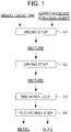
- Fig. 1 is a flow chart illustrating the flow of a method for smelting nickel oxide ore.
- the method for smelting nickel oxide ore according to the present embodiment has a mixing step S1 for mixing raw materials including nickel oxide ore, a drying step S2 for drying the obtained mixture, a reducing step S3 for reducing the mixture after being dried by heating the mixture at a predetermined reducing temperature, and a recovering step S4 for separating the metal and the slag which are reduction products thus obtained and recovering the metal.
- the mixing step S1 is a step for mixing raw material powders including nickel oxide ore to obtain a mixture. Specifically, in the mixing step S1, nickel oxide ore, which is a raw material ore, and a carbonaceous reducing agent are mixed, and powders of iron ore, a flux component, a binder, and the like having a particle diameter of, for example, about 0.1 mm to 0.8 mm as additives of arbitrary components are mixed, thereby obtaining a mixture.
- the mixing can be performed by adding a predetermined amount of water.
- the mixing property of the raw material powders can be improved.
- the mixing treatment can be performed by using a known mixing machine or the like.
- kneading may be performed at the same time as mixing of the respective raw material powders in order to enhance the mixing property.
- a shear force is applied to the mixture obtained by mixing the raw material powders, and thus the aggregation of the raw material ore, the carbonaceous reducing agent, and the like can be untangled, the mixing can be more uniformly performed, voids between respective particles can be decreased, and uniform reaction can be caused to occur when the mixture is subject to the reduction treatment.
- the kneading can be performed by using a twin-screw kneader or the like.
- the nickel oxide ore which is a raw material ore is not particularly limited, but limonite ore, saprolite ore, and the like can be used.
- the nickel oxide ore contains nickel oxide (NiO) and iron oxide (Fe 2 O 3 ) as a structural component.
- classification, pulverization, and the like into a predetermined size may be performed.
- classification, pulverization, and the like By performing classification, pulverization, and the like, the particle diameters can be aligned in a certain degree of range, ores having a large size are removed by pulverization and the like to enhance the mixing property of the carbonaceous reducing agent or the like, and uniformity at the time of the reduction treatment can be improved.
- the carbonaceous reducing agent is not particularly limited, but examples thereof include a coal powder and a coke powder.
- the carbonaceous reducing agent has a size equivalent to the particle size of the aforementioned nickel oxide ore which is a raw material ore. According to this, the mixing property of the nickel oxide ore can be enhanced and uniformity at the time of the reduction treatment can be improved.
- the amount of the carbonaceous reducing agent mixed is set to preferably a proportion of 80% by mass or less and more preferably 60% by mass or less when the amount of the carbonaceous reducing agent required for reducing nickel oxide and iron oxide constituting the nickel oxide ore without excess or deficiency is taken as 100% by mass.
- the amount of the carbonaceous reducing agent mixed is set to a proportion of 80% by mass or less with respect to 100% by mass of the total value of chemical equivalents, the reduction reaction can be efficiently advanced.
- the lower limit value of the amount of the carbonaceous reducing agent mixed is not particularly limited, but is set to preferably a proportion of 15% by mass or more and more preferably a proportion of 20% by mass or more with respect to 100% by mass of the total value of chemical equivalents.
- the amount of the carbonaceous reducing agent required for reducing nickel oxide and iron oxide without excess or deficiency can be rephrased as the total amount of a chemical equivalent required for reducing the entire amount of nickel oxide into nickel metal and a chemical equivalent required for reducing iron oxide into iron metal (hereinafter, also referred to as the "total value of chemical equivalents").
- the iron ore which is an additive of an arbitrary component, is not particularly limited, but, for example, iron ore having an iron grade of about 50% by mass or more, hematite to be obtained by hydrometallurgy of nickel oxide ore, and the like can be used.
- binder may include bentonite, a polysaccharide, a resin, water glass, and dehydrated cake.
- examples of the flux component may include calcium oxide, calcium hydroxide, calcium carbonate, and silicon dioxide.
- composition (% by weight) of some of raw material powders to be mixed in the mixing step S1 is presented in the following Table 1. Incidentally, the composition of the raw material powders is not limited thereto.
- Table 1 Raw material powder [% by weight] Ni Fe 2 O 3 C Nickel oxide ore 1 ⁇ 2 50 ⁇ 60 - Carbonaceous reducing agent - - ⁇ 85 Iron ore - 80 ⁇ 95 -
- the drying step S2 is a step for drying the obtained mixture.
- the mixture obtained through the aforementioned mixing step S1 may be charged into a reducing furnace, which will be described below, without any changes and subjected to the reduction treatment (reducing step S3), but the mixture may be dried prior to the reduction treatment.
- the mixture after being dried is charged into the reducing furnace and then subjected to the treatment in the reducing step S3.
- the reduction treatment can be uniformly performed with respect to this mixture, and the mixture can be reliably heated to a temperature equal to or more than the melting temperature and can be reduced.
- the drying temperature is not particularly limited, but is preferably set in a range of 150°C or more and 400°C or less.
- the drying treatment is performed in such a range, the mixture can be efficiently dried while suppressing the progress of the reaction of the mixture in this treatment.
- the mixture is molded in a predetermined shape and then subjected to the reduction treatment, by drying the mixture in the above-described temperature range, it is possible to prevent the molded product from being rapidly heated and ruptured by the reduction treatment.
- the drying method is not particularly limited. For example, a method in which a mixture is charged into a drying facility of which inside temperature is adjusted to a predetermined drying temperature and the temperature is kept for a predetermined time to dry the mixture, a method in which hot air at a predetermined drying temperature is blown to a mixture and the mixture is dried, and the like can be mentioned.
- an exhaust gas generated in a reducing furnace in which heat reduction is performed may be used and the mixture may be dried.
- the exhaust gas generated through the reduction treatment is extremely high temperature, and thus is suitable for drying a mixture containing nickel oxide ore.
- the drying treatment in which a gas flow rate is suppressed can be performed, and accordingly, a dust generation rate in the drying treatment can be suppressed.
- piping is configured to connect the reducing furnace and the drying facility, and the exhaust gas generated from the reducing furnace is transferred directly to the drying facility.
- composition of the mixture after being subjected to the drying treatment is presented in the following Table 2.
- the composition of the mixture is not limited thereto.
- Table 2 Composition of solid component in mixture after being dried
- Ni Fe 2 O 3 SiO 2 CaO Al 2 O 3 MgO Binder Others 0.5 ⁇ 1.5 50 ⁇ 60 8 ⁇ 15 4 ⁇ 8 1 ⁇ 6 2 ⁇ 7 About 1 Remainder
- the drying treatment may be performed at the same time as mixing in the aforementioned mixing step S1, and in the case of also performing drying in the mixing step S1 in this way, the case of using, as a raw material, an ore which does not need to be dried, and the like, the drying step S2 can also be omitted.
- mixing may be performed after drying, and steps may be appropriately selected depending on properties of the ore, the carbonaceous reducing agent, and the like.
- the reducing step S3 is a step for charging the mixture into a reducing furnace and reducing the mixture to thereby generate a metal and slag.
- a reducing furnace having a burner hereinafter, also referred to as the "burner furnace" and the mixture is heated by the burner to thereby reduce an oxide ore.
- the burner furnace In a heat reduction treatment by this burner, the mixture is melted in accordance to the progress of the reduction reaction, and thereby a metal and slag in a molten state are generated.
- the reduction reaction of nickel oxide ore is gradually advanced in accordance with heating of the mixture charged into the furnace by the burner, the reduction reaction occurs also in a solid state before the mixture is brought into a molten state.
- the state of the mixture is gradually changed by burner heating from a solid state to a liquid state, that is, a molten state, and finally, a metal and slag in a molten state, which are generated by the heat reduction treatment by the burner, are obtained.
- the mixture can be brought into only a semi-molten state, and in this state, it takes a long period of time for metal grains to grow, and thus there is a problem of an increase in cost.
- the semi-molten product adheres to the inside of the kiln and this product grows, the operation has to be stopped for maintenance, and there is a problem in that the operation efficiency is significantly decreased.
- the mixture is brought into a molten state accordance with the progress of the reduction reaction, a metal and slag in a molten state are finally generated, and the metal and the slag in a molten state can be easily separated by a difference in specific gravity.
- the metal in a molten state molten metal
- the difference in specific gravity even if a variation in oxygen partial pressure or CO partial pressure occurs in the atmosphere in the furnace, the influence on the composition of the metal accumulating below the slag at the bottom of the furnace can be suppressed.
- the treatment can be performed at significantly lower cost as compared to heating using electricity or the like, and thus economic efficiency can also be enhanced.
- the fuel for example, LPG gas, LNG gas, coal, coke, pulverized coal, and the like are used, the cost of these fuels is very inexpensive, and facility cost or maintenance cost can also be suppressed to significantly low as compared to an electric furnace and the like.
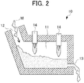
- Fig. 2 is a diagram (cross-sectional view) schematically illustrating a configuration example of a reducing furnace having a burner.
- a reducing furnace 10 includes a treatment unit 11 which heats a mixture M to perform a reduction treatment, a charging port 12 used for charging the mixture M into the treatment unit 11, and a discharging port 13 used for discharging a metal obtained by the reduction treatment.
- an inner wall or a hearth of the treatment unit 11 is preferably protected by slag coating. According to this, damages of the furnace can be prevented, a continuous operation can be performed over a long period of time, and thus facility cost or maintenance cost can be reduced.
- a burner 14 is provided at the upper part thereof.
- the mixture M charged from the charging port 12 is heated by the burner 14, and the reduction reaction of reducing nickel oxide ore by the carbonaceous reducing agent contained in the mixture M is caused to occur.
- the reduction reaction is caused to occur and the mixture is brought into a molten state in accordance with the progress of the reduction reaction. That is, the reducing furnace 10 is a melt-reducing furnace.
- a metal and slag in a molten state are generated by such a reduction reaction, and reduction products in which the slag and the metal are separated into the upper layer and the lower layer, respectively, by a difference in specific gravity are obtained.
- the metal in a molten state separated by a difference in specific gravity is discharged from the discharging port 13.
- the discharging port 13 is provided at a position where the metal constituting the lower layer in the reduction product (metal layer) exists, and the metal separated by a difference in specific gravity can be selectively discharged and recovered.
- a slag discharging port can be provided at the upper side of the discharging port 13, and the slag separated by a difference in specific gravity and constituting the upper layer can also be selectively discharged.
- the fuel of the burner is not particularly limited, and may be a solid, a liquid, or a gas.
- a solid fuel such as coke, coal, or pulverized coal
- a liquid fuel such as A-heavy oil or C-heavy oil
- a gas fuel such as LNG or LPG
- a burner using a gas fuel is preferred because the combustion is relatively stable, the temperature is easily controlled, and a high temperature can be realized.
- the air-fuel ratio of the burner is preferably controlled in a predetermined range. Specifically, the mixture is heated by controlling the air-fuel ratio of the burner preferably in a range of 0.8 or more and 1.1 or less and more preferably in a range of 0.85 or more and 0.95 or less.
- the air-fuel ratio refers to a mass ratio of air to fuel.
- the reduction reaction can be advanced in a short time, and the mixture can be melted in a short time. Further, the metal and the slag in a molten state thus generated can be separated by a difference in specific gravity in a short time. From these points of view, the oxidation of the metal generated by the reduction reaction is relatively hardly advanced. However, by controlling the air-fuel ratio of the burner in a predetermined range, the oxygen concentration in the atmosphere in the furnace is decreased so that the oxidation of the metal can be further suppressed, and thereby high quality ferronickel can be stably produced. From this point of view, by performing heating while controlling the air-fuel ratio of the burner preferably to 0.8 or more and 1.1 or less, high quality ferronickel can be stably produced.
- heating is preferably performed such that temperatures of the metal and the slag to be obtained are each in a range of 1300°C or more and 1700°C or less.
- heating is preferably performed such that temperature of a metal to be obtained is in a range of 1400°C or more and 1600°C or less and the temperature of slag is in a range of 1480°C or more and 1680°C or less.
- control of temperatures of a metal and slag to be obtained can be performed by controlling a heating temperature by increasing or decreasing a fuel heating value in the burner, or the like.
- the recovering step S4 is a step for separating the metal and the slag obtained by reduction to recover a metal.
- a molten metal and molten slag are generated. Since the metal has a larger specific gravity and is heavier than the slag, the metal and the slag each are naturally separated by a difference in specific gravity, and the metal accumulates at the furnace bottom of the reducing furnace. Therefore, the metal is taken out from the vicinity of furnace bottom of the reducing furnace and then recovered, and thereby only the metal can be selectively recovered.
- the slag floats on the metal, for example, the slag can be taken out from the furnace wall and recovered. In this way, since the metal and the slag thus obtained are in a molten state, the metal and the slag can be easily separated by a difference in specific gravity thereof and recovered.
- the metal and the slag may be recovered from one hole of the reducing furnace in a state of being mixed.
- the structure of the reducing furnace can be simplified, and workability can also be improved.
- the recovered metal and slag are cooled, solidified, and then separated by magnetic separation or the like, and thereby the metal can be recovered.
- the metal and the slag since the metal and the slag have already been separated when being in a molten state, basically, even in a solid state, the state of the metal and the slag being separated is maintained, and thus the metal can be easily recovered even by a method such as magnetic separation.
- the metal can be recovered at a high recovery rate.
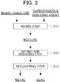
- Fig. 3 is a flow chart illustrating the flow of a method for smelting nickel oxide ore according to a second embodiment. As illustrated in Fig. 3 , in the smelting method according to the second embodiment, unlike the smelting method according to the first embodiment, the drying step and the reducing step are combined and then executed.
- the method for smelting nickel oxide ore according to the second embodiment has a mixing step S11 for mixing raw materials including nickel oxide ore, a drying and reducing step S12 for charging the obtained mixture into a reducing furnace and performing a drying treatment and a reduction treatment, and a recovering step S13 for separating the metal and the slag which are reduction products thus obtained and recovering the metal.
- the mixing step S11 and the recovering step S13 correspond to the mixing step S1 and the recovering step S4, respectively, in the smelting method according to the first embodiment and the same treatments are performed, the detailed description herein will be omitted.
- the description of the treatments which are in common with those of the drying step S2 and the reducing step S3 in the smelting method according to the first embodiment will be omitted, and only the different content will be described in detail.
- the drying and reducing step S12 is a step for charging the mixture, which contains at least nickel oxide ore and a carbonaceous reducing agent, obtained through the mixing step S11 into a reducing furnace, performing a drying treatment with respect to the mixture in the reducing furnace, and reducing the mixture after being dried with a continuous operation by heating the mixture by the burner.
- a reducing furnace to which a drying facility is directly connected is used, and the drying treatment and the reduction treatment are performed in this reducing furnace.
- a gas (exhaust gas) generated by performing the reduction treatment is introduced directly into the drying facility from the reducing furnace, and the drying treatment is performed by using this gas.
- the reducing furnace to which the drying facility is directly connected is used, and the drying treatment and the reduction treatment are performed in the reducing furnace, and thereby the gas generated by the reduction treatment can be effectively used as a gas for drying the mixture, that is, a drying gas. According to this, there is no need for securing a separate heat source used for the drying treatment and thus the operation can be efficiently performed.
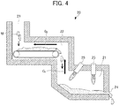
- Fig. 4 is a diagram schematically illustrating a configuration example of a reducing furnace having a burner and a diagram (cross-sectional view) illustrating the configuration of the reducing furnace to which a drying facility is directly connected.
- a reducing furnace 20 includes a reduction treatment unit 21 in which a reduction treatment is performed by heating a mixture M and a drying treatment unit 22 in which the mixture M is subjected to a drying treatment prior to the reduction treatment in the reduction treatment unit 21.
- the reduction treatment unit 21 and the drying treatment unit 22 are directly connected to each other to constitute the reducing furnace 20.
- the reducing furnace 20 includes a charging port 23 used for charging the mixture M and a discharging port 24 used for discharging the metal obtained by the reduction treatment.
- an inner wall of the reducing furnace 20, particularly, an inner wall or a hearth of the reduction treatment unit 21 is preferably protected by slag coating.
- the mixture M charged from the charging port 23 is supplied to the drying treatment unit 22.
- the drying treatment unit 22 is configured, for example, by a belt conveyor device as illustrated in Fig. 4 .
- the supplied mixture M is placed on the belt of the belt conveyor device and the drying treatment is performed in the process of the mixture moving on the belt at a predetermined speed.
- a burner 25 is provided at the upper part thereof.
- the mixture (mixture after being dried) M transferred through the drying treatment in the drying treatment unit 22 is supplied, this mixture M is heated by the burner 25 to be brought into a molten state, and the reduction reaction is caused to occur by a carbonaceous reducing agent contained in the mixture M.
- the reducing furnace 20 is a melt-reducing furnace.
- a metal and slag are generated by such a reduction reaction, and reduction products in which the slag and the metal are separated into the upper layer and the lower layer, respectively, by a difference in specific gravity are obtained.
- the reduction treatment unit 21 and the drying treatment unit 22 are configured to be directly connected to each other. More specifically, as illustrated in Fig. 4 , in a positional relationship in a height direction, the drying treatment unit 22 and the reduction treatment unit 21 are positioned at an upper side and a lower side, respectively, and are provided in the same space. Further, the reduction treatment unit 21 and the drying treatment unit 22 are connected in a state of communicating with each other.
- a gas (exhaust gas) generated by the reduction treatment in the reduction treatment unit 21 is introduced by the upward-flowing stream thereof directly into the drying treatment unit 22 positioned at the upper side in the height direction in relation to the reduction treatment unit 21, as indicated by arrow G 1 in Fig. 4 .
- a gas introduced directly from the reduction treatment unit 21 is used as a drying gas and the drying treatment is performed (arrow G 2 in Fig. 4 ).
- the gas generated by the reduction treatment in the reduction treatment unit 21 is an exhaust gas generated by the treatment at a high reducing temperature, and thus this gas is in a high-temperature state. Therefore, this gas can be suitably used as a drying gas.
- this high-temperature gas is used as a drying gas, there is no need for performing heating or the like again, and the cost can be effectively reduced.
- the gas obtained through the reduction treatment is a reducing gas. Therefore, in the drying treatment unit 22, by performing the drying treatment using such a high-temperature gas having reducing property as a drying gas, the oxidation of the mixture can be effectively prevented. According to this, when the mixture M after being dried is subjected to the reduction treatment, uniform reduction reaction can be caused to occur without excess or deficiency, and a high quality metal can be produced.
- a mixture was obtained by mixing nickel oxide ore as a raw material ore, iron ore, quartz and limestone which were flux components, a binder, and a carbonaceous reducing agent (coal powder, carbon content: 82% by mass, average particle diameter: about 65 ⁇ m) by using a mixing machine while adding an appropriate amount of water.
- the carbonaceous reducing agent was contained in an amount to be a proportion of 27% by mass when the amount required for reducing nickel oxide (NiO) and iron oxide (Fe 2 O 3 ) contained in the nickel oxide ore without excess or deficiency was taken as 100% by mass.
- Example 1 the obtained mixture was charged directly into a drying facility without being molded and was subjected to the drying treatment at a temperature of 180°C or more for 1 hour, and the mixture after being dried was charged into a reducing furnace having a burner (burner furnace).
- a gas burner using a gas fuel was used as the burner.
- the charged mixture was heated by the burner to be brought into a molten state and then was subjected to the reduction treatment.
- a metal and slag in a molten state were generated in the burner furnace, and the slag and the metal were separated into the upper layer and the lower layer, respectively, by a difference in specific gravity.
- the reduction treatment the operation was divided into Examples 1-1 to 1-5, and the mixture was heated and reduced such that temperatures of the metal and the slag to be obtained were set to temperatures presented in the following Table 3 as the reducing temperature in each operation.
- Comparative Example 1 the obtained mixture was granulated by a pan type granulator and sieved to a size of ⁇ 14.0 ⁇ 0.5 mm. Thereafter, the drying treatment at 180°C or more for 1 hour was performed in the drying facility. Thereafter, the dried samples were divided into four (Comparative Examples 1-1 to 1-4) and subjected to the reduction treatment by using a rotary hearth furnace. Incidentally, in the reduction treatment, reduction was performed such that the reducing temperature was set to a furnace temperature presented in the following Table 3.
- Example 1 the time required for the reduction treatment (reducing time) was measured.
- the reducing time refers to an average time from the mixture containing nickel oxide ore being charged into the reducing furnace to the metal and the slag in a molten state thus generated being discharged from the reducing furnace.
- Example 1 the molten metal was taken out from the vicinity of the furnace bottom of the burner furnace and recovered.
- Comparative Example 1 the reduction product obtained after the reduction treatment was pulverized and then subjected to magnetic separation to recover a metal.
- the nickel content in the metal was measured by using an ICP emission spectroscopic analyzer (SHIMAZU S-8100), the metallized rate of nickel was calculated by the following Equation (1), and the nickel content rate in the metal was calculated by the following Equation (2).
- Metallized rate of nickel amount of metallized Ni in pellet ⁇ amount of entire nickel in pellet ⁇ 100 %
- Nickel content rate in metal amount of metallized Ni in pellet ⁇ total amount of metallized nickel and iron in pellet ⁇ 100 %
- the recovery rate of nickel metal was calculated by the following Equation (3) from the nickel content rate in the nickel oxide ore subjected to the reduction treatment and the charged amount thereof and the amount of the recovered nickel.
- Recovery rate of nickel metal amount of recovered nickel ⁇ amount of charged ore ⁇ nickel content ratio in ore ⁇ 100 [Table 3] Reducing furnace Reducing temperature Reducing time (minute) Metallized rate of nickel (%) Nickel content rate in metal (%) Recovery rate of metal (%) Metal temperature (°C) Slag temperature (°C) Furnace temperature (°C)
- Example 1-1 Burner furnace 1420 1500 - 20 98.5 18.0 98.1
- Comparative Examples 1-1 to 1-4 which were subjected to the reduction treatment according to a conventional method by using a rotary hearth furnace, lower values than those in Examples were obtained in all of the metallized rate of nickel, the nickel content rate in the metal, and the recovery rate of metal. In addition, the reducing time was longer in the methods of Comparative Examples 1-1 to 1-4 than in Examples.
- Example 2 the drying treatment and the reduction treatment were performed by using a reducing furnace (burner furnace) to which a drying facility was directly connected as exemplified in Fig. 4 .
- the mixture was dried by using, as a drying gas, a gas generated by the reduction treatment in the drying facility (the drying treatment unit 22 in Fig. 4 ).
- the mixture after being dried was heated by the burner in a main body (the reduction treatment unit 21 in Fig. 4 ) of the reducing furnace so as to be melted.
- operations were performed in the same manner as in Example 1 except for the above-described matters.
- the molten metal was taken out from the vicinity of the furnace bottom of the burner furnace and recovered, and the metallized rate of nickel, the nickel content in the metal (nickel grade), and the recovery rate of metal were analyzed respectively for the obtained metal samples.
- the analysis results are presented in the following Table 4.
- Example 2-1 Directly connected to burner furnace Burner furnace 1435 1500 18 97.7 18.0 97.1
- Example 2-2 Directly connected to burner furnace Burner furnace 1455 1550 13 98.2 18.2 98.3
- Example 2-3 Directly connected to burner furnace Burner furnace 1500 1580 11 98.5 18.3 98.4
- Example 2-4 Directly connected to burner furnace Burner furnace 1550 1630 8 98.6 18.5 98.2
- Example 2-5 Directly connected to burner furnace Burner furnace 1600 1660 6 98.2 18.4 98.6
Applications Claiming Priority (2)
| Application Number | Priority Date | Filing Date | Title |
|---|---|---|---|
| JP2018176524A JP7147409B2 (ja) | 2018-09-20 | 2018-09-20 | 酸化鉱石の製錬方法 |
| PCT/JP2019/035891 WO2020059630A1 (fr) | 2018-09-20 | 2019-09-12 | Procédé de fusion de minerai d'oxyde |
Publications (3)
| Publication Number | Publication Date |
|---|---|
| EP3854894A1 true EP3854894A1 (fr) | 2021-07-28 |
| EP3854894A4 EP3854894A4 (fr) | 2022-05-18 |
| EP3854894B1 EP3854894B1 (fr) | 2024-02-14 |
Family
ID=69888495
Family Applications (1)
| Application Number | Title | Priority Date | Filing Date |
|---|---|---|---|
| EP19862577.4A Active EP3854894B1 (fr) | 2018-09-20 | 2019-09-12 | Procédé de fusion de minerai d'oxyde |
Country Status (8)
| Country | Link |
|---|---|
| US (1) | US20210238710A1 (fr) |
| EP (1) | EP3854894B1 (fr) |
| JP (1) | JP7147409B2 (fr) |
| CN (1) | CN112601827A (fr) |
| AU (1) | AU2019342986B2 (fr) |
| CA (1) | CA3110025A1 (fr) |
| PH (1) | PH12021550379A1 (fr) |
| WO (1) | WO2020059630A1 (fr) |
Families Citing this family (1)
| Publication number | Priority date | Publication date | Assignee | Title |
|---|---|---|---|---|
| JP2023050953A (ja) * | 2021-09-30 | 2023-04-11 | 株式会社クボタ | 溶融炉及び溶融炉の運転方法 |
Family Cites Families (14)
| Publication number | Priority date | Publication date | Assignee | Title |
|---|---|---|---|---|
| US3953196A (en) * | 1974-04-05 | 1976-04-27 | Obenchain Richard F | Process for the direct reduction of metal oxides |
| DE3540541A1 (de) * | 1985-11-15 | 1987-05-21 | Metallgesellschaft Ag | Verfahren zur reduktion von hoeheren metalloxiden zu niedrigen metalloxiden |
| JPS6462438A (en) * | 1987-08-31 | 1989-03-08 | Hyuga Smelting | Electric furnace smelting method for nickel-containing ore |
| ZA909149B (en) * | 1989-06-02 | 1991-12-24 | Cra Services | Manufacture of ferroalloys using a molten bath reactor |
| WO1997020954A1 (fr) * | 1995-12-06 | 1997-06-12 | Wmc Resources Ltd. | Procede duplex simplifie de traitement de minerais et/ou concentres de nickel en vue de la production de ferronickels, de fers au nickel et d'aciers inoxydables |
| JP4149531B2 (ja) * | 1996-09-27 | 2008-09-10 | 株式会社神戸製鋼所 | 金属鉄の製造方法及び製造設備 |
| CN101481753B (zh) * | 2008-12-05 | 2010-08-11 | 首钢总公司 | 一种从红土氧化镍矿冶炼镍铁合金的方法 |
| JP2010270954A (ja) * | 2009-05-21 | 2010-12-02 | Hyuga Seirensho:Kk | ロータリーキルンの操業方法 |
| CN101845326B (zh) * | 2009-10-23 | 2012-12-12 | 湖南安淳高新技术有限公司 | 旋流式熔融池气化炉 |
| JP5503420B2 (ja) | 2010-06-07 | 2014-05-28 | 株式会社神戸製鋼所 | 粒状金属の製造方法 |
| WO2015015468A1 (fr) * | 2013-08-02 | 2015-02-05 | Louis Johannes Fourie | Produit de ferronickel et procédé permettant sa production |
| JP6428528B2 (ja) * | 2015-08-10 | 2018-11-28 | 住友金属鉱山株式会社 | ニッケル酸化鉱の製錬方法 |
| CN106609325B (zh) * | 2015-10-27 | 2019-07-05 | 中国恩菲工程技术有限公司 | 富氧煤粉熔融还原红土镍矿工艺和熔融还原炉 |
| RU2639396C1 (ru) * | 2017-01-10 | 2017-12-21 | Федеральное государственное бюджетное учреждение науки Институт металлургии Уральского отделения Российской академии наук (ИМЕТ УрО РАН) | Способ пирометаллургической переработки окисленной никелевой руды |
-
2018
- 2018-09-20 JP JP2018176524A patent/JP7147409B2/ja active Active
-
2019
- 2019-09-12 WO PCT/JP2019/035891 patent/WO2020059630A1/fr unknown
- 2019-09-12 EP EP19862577.4A patent/EP3854894B1/fr active Active
- 2019-09-12 CN CN201980055170.0A patent/CN112601827A/zh active Pending
- 2019-09-12 CA CA3110025A patent/CA3110025A1/fr active Pending
- 2019-09-12 AU AU2019342986A patent/AU2019342986B2/en active Active
- 2019-09-12 US US17/268,611 patent/US20210238710A1/en active Pending
-
2021
- 2021-02-22 PH PH12021550379A patent/PH12021550379A1/en unknown
Also Published As
| Publication number | Publication date |
|---|---|
| CN112601827A (zh) | 2021-04-02 |
| EP3854894B1 (fr) | 2024-02-14 |
| AU2019342986A1 (en) | 2021-03-18 |
| JP2020045542A (ja) | 2020-03-26 |
| PH12021550379A1 (en) | 2021-11-29 |
| EP3854894A4 (fr) | 2022-05-18 |
| AU2019342986B2 (en) | 2022-12-01 |
| JP7147409B2 (ja) | 2022-10-05 |
| CA3110025A1 (fr) | 2020-03-26 |
| WO2020059630A1 (fr) | 2020-03-26 |
| US20210238710A1 (en) | 2021-08-05 |
Similar Documents
| Publication | Publication Date | Title |
|---|---|---|
| US8557019B2 (en) | Process for production of nickel and cobalt using metal hydroxide, metal oxide and/or metal carbonate | |
| JP7439540B2 (ja) | 酸化鉱石の製錬方法 | |
| EP3447157B1 (fr) | Procédé de fusion de minerai d'oxyde | |
| EP3854894B1 (fr) | Procédé de fusion de minerai d'oxyde | |
| JP2018127693A (ja) | 金属酸化物の製錬方法 | |
| JP5168802B2 (ja) | 焼結鉱の製造方法 | |
| WO2018194165A1 (fr) | Procédé de fusion métallurgique d'un oxyde métallique | |
| JP2018127694A (ja) | 金属酸化物の製錬方法 | |
| JP2018178219A (ja) | 酸化鉱石の製錬方法 | |
| JP7459660B2 (ja) | 酸化鉱石の製錬方法 | |
| JP7415369B2 (ja) | 酸化鉱石の製錬方法 | |
| JP2020056052A (ja) | 酸化鉱石の製錬方法 | |
| JP3732024B2 (ja) | 還元鉄ペレットの製造方法 | |
| JP7293910B2 (ja) | 酸化鉱石の製錬方法 | |
| JP7211178B2 (ja) | ニッケル酸化鉱石の製錬方法 | |
| JP2021167461A (ja) | 酸化鉱石の製錬方法 | |
| JP6798079B2 (ja) | 酸化鉱石の製錬方法 | |
| JP7124588B2 (ja) | 酸化鉱石の製錬方法 | |
| JP2023158803A (ja) | ニッケル酸化鉱石の製錬方法 | |
| WO2023171468A1 (fr) | Procédé de fabrication de minerai aggloméré contenant un matériau carboné, et procédé de fabrication de fonte brute fondue | |
| JP7167534B2 (ja) | 酸化鉱石の製錬方法 | |
| JP2020056053A (ja) | 酸化鉱石の製錬方法 | |
| JP2022119615A (ja) | ニッケル酸化鉱石の製錬方法 | |
| JP2024010512A (ja) | ニッケル酸化鉱石の製錬方法 | |
| JP2024010514A (ja) | ニッケル酸化鉱石の製錬方法 |
Legal Events
| Date | Code | Title | Description |
|---|---|---|---|
| STAA | Information on the status of an ep patent application or granted ep patent |
Free format text: STATUS: THE INTERNATIONAL PUBLICATION HAS BEEN MADE |
|
| PUAI | Public reference made under article 153(3) epc to a published international application that has entered the european phase |
Free format text: ORIGINAL CODE: 0009012 |
|
| STAA | Information on the status of an ep patent application or granted ep patent |
Free format text: STATUS: REQUEST FOR EXAMINATION WAS MADE |
|
| 17P | Request for examination filed |
Effective date: 20210324 |
|
| AK | Designated contracting states |
Kind code of ref document: A1 Designated state(s): AL AT BE BG CH CY CZ DE DK EE ES FI FR GB GR HR HU IE IS IT LI LT LU LV MC MK MT NL NO PL PT RO RS SE SI SK SM TR |
|
| DAV | Request for validation of the european patent (deleted) | ||
| DAX | Request for extension of the european patent (deleted) | ||
| A4 | Supplementary search report drawn up and despatched |
Effective date: 20220422 |
|
| RIC1 | Information provided on ipc code assigned before grant |
Ipc: C22B 1/243 20060101ALI20220414BHEP Ipc: C22C 1/02 20060101ALI20220414BHEP Ipc: C22C 33/04 20060101ALI20220414BHEP Ipc: C22B 5/10 20060101ALI20220414BHEP Ipc: C21B 13/00 20060101ALI20220414BHEP Ipc: C22B 23/02 20060101AFI20220414BHEP |
|
| STAA | Information on the status of an ep patent application or granted ep patent |
Free format text: STATUS: EXAMINATION IS IN PROGRESS |
|
| 17Q | First examination report despatched |
Effective date: 20230621 |
|
| REG | Reference to a national code |
Ref country code: DE Ref legal event code: R079 Ref document number: 602019046678 Country of ref document: DE Free format text: PREVIOUS MAIN CLASS: C22B0023020000 Ipc: C22B0001243000 Ref country code: DE Ref legal event code: R079 Ipc: C22B0001243000 |
|
| GRAP | Despatch of communication of intention to grant a patent |
Free format text: ORIGINAL CODE: EPIDOSNIGR1 |
|
| STAA | Information on the status of an ep patent application or granted ep patent |
Free format text: STATUS: GRANT OF PATENT IS INTENDED |
|
| RIC1 | Information provided on ipc code assigned before grant |
Ipc: C22C 33/04 20060101ALI20230903BHEP Ipc: C22C 1/02 20060101ALI20230903BHEP Ipc: C22B 23/02 20060101ALI20230903BHEP Ipc: C22B 5/10 20060101ALI20230903BHEP Ipc: C22B 1/243 20060101AFI20230903BHEP |
|
| GRAJ | Information related to disapproval of communication of intention to grant by the applicant or resumption of examination proceedings by the epo deleted |
Free format text: ORIGINAL CODE: EPIDOSDIGR1 |
|
| INTG | Intention to grant announced |
Effective date: 20231010 |
|
| RAP3 | Party data changed (applicant data changed or rights of an application transferred) |
Owner name: SUMITOMO METAL MINING CO., LTD. |
|
| RIN1 | Information on inventor provided before grant (corrected) |
Inventor name: ISEKI, TAKASHI |
|
| STAA | Information on the status of an ep patent application or granted ep patent |
Free format text: STATUS: EXAMINATION IS IN PROGRESS |
|
| GRAP | Despatch of communication of intention to grant a patent |
Free format text: ORIGINAL CODE: EPIDOSNIGR1 |
|
| STAA | Information on the status of an ep patent application or granted ep patent |
Free format text: STATUS: GRANT OF PATENT IS INTENDED |
|
| INTC | Intention to grant announced (deleted) | ||
| INTG | Intention to grant announced |
Effective date: 20231123 |
|
| P01 | Opt-out of the competence of the unified patent court (upc) registered |
Effective date: 20231117 |
|
| GRAS | Grant fee paid |
Free format text: ORIGINAL CODE: EPIDOSNIGR3 |
|
| GRAA | (expected) grant |
Free format text: ORIGINAL CODE: 0009210 |
|
| STAA | Information on the status of an ep patent application or granted ep patent |
Free format text: STATUS: THE PATENT HAS BEEN GRANTED |
|
| AK | Designated contracting states |
Kind code of ref document: B1 Designated state(s): AL AT BE BG CH CY CZ DE DK EE ES FI FR GB GR HR HU IE IS IT LI LT LU LV MC MK MT NL NO PL PT RO RS SE SI SK SM TR |
|
| REG | Reference to a national code |
Ref country code: GB Ref legal event code: FG4D |
|
| REG | Reference to a national code |
Ref country code: CH Ref legal event code: EP |
|
| REG | Reference to a national code |
Ref country code: DE Ref legal event code: R096 Ref document number: 602019046678 Country of ref document: DE |
|
| REG | Reference to a national code |
Ref country code: IE Ref legal event code: FG4D |