EP3848637B1 - Ofen und kochverfahren dafür - Google Patents
Ofen und kochverfahren dafür Download PDFInfo
- Publication number
- EP3848637B1 EP3848637B1 EP20747646.6A EP20747646A EP3848637B1 EP 3848637 B1 EP3848637 B1 EP 3848637B1 EP 20747646 A EP20747646 A EP 20747646A EP 3848637 B1 EP3848637 B1 EP 3848637B1
- Authority
- EP
- European Patent Office
- Prior art keywords
- light
- cooking
- cooking product
- product
- wavelength band
- Prior art date
- Legal status (The legal status is an assumption and is not a legal conclusion. Google has not performed a legal analysis and makes no representation as to the accuracy of the status listed.)
- Active
Links
Images



Classifications
-
- F—MECHANICAL ENGINEERING; LIGHTING; HEATING; WEAPONS; BLASTING
- F24—HEATING; RANGES; VENTILATING
- F24C—DOMESTIC STOVES OR RANGES ; DETAILS OF DOMESTIC STOVES OR RANGES, OF GENERAL APPLICATION
- F24C7/00—Stoves or ranges heated by electric energy
- F24C7/08—Arrangement or mounting of control or safety devices
- F24C7/082—Arrangement or mounting of control or safety devices on ranges, e.g. control panels, illumination
- F24C7/085—Arrangement or mounting of control or safety devices on ranges, e.g. control panels, illumination on baking ovens
-
- G—PHYSICS
- G01—MEASURING; TESTING
- G01B—MEASURING LENGTH, THICKNESS OR SIMILAR LINEAR DIMENSIONS; MEASURING ANGLES; MEASURING AREAS; MEASURING IRREGULARITIES OF SURFACES OR CONTOURS
- G01B11/00—Measuring arrangements characterised by the use of optical techniques
- G01B11/02—Measuring arrangements characterised by the use of optical techniques for measuring length, width or thickness
-
- G—PHYSICS
- G01—MEASURING; TESTING
- G01N—INVESTIGATING OR ANALYSING MATERIALS BY DETERMINING THEIR CHEMICAL OR PHYSICAL PROPERTIES
- G01N21/00—Investigating or analysing materials by the use of optical means, i.e. using sub-millimetre waves, infrared, visible or ultraviolet light
- G01N21/17—Systems in which incident light is modified in accordance with the properties of the material investigated
- G01N21/25—Colour; Spectral properties, i.e. comparison of effect of material on the light at two or more different wavelengths or wavelength bands
- G01N21/255—Details, e.g. use of specially adapted sources, lighting or optical systems
-
- F—MECHANICAL ENGINEERING; LIGHTING; HEATING; WEAPONS; BLASTING
- F24—HEATING; RANGES; VENTILATING
- F24C—DOMESTIC STOVES OR RANGES ; DETAILS OF DOMESTIC STOVES OR RANGES, OF GENERAL APPLICATION
- F24C3/00—Stoves or ranges for gaseous fuels
- F24C3/12—Arrangement or mounting of control or safety devices
- F24C3/126—Arrangement or mounting of control or safety devices on ranges
- F24C3/128—Arrangement or mounting of control or safety devices on ranges in baking ovens
-
- G—PHYSICS
- G01—MEASURING; TESTING
- G01N—INVESTIGATING OR ANALYSING MATERIALS BY DETERMINING THEIR CHEMICAL OR PHYSICAL PROPERTIES
- G01N2201/00—Features of devices classified in G01N21/00
- G01N2201/06—Illumination; Optics
- G01N2201/062—LED's
- G01N2201/0627—Use of several LED's for spectral resolution
Definitions
- This invention relates to an oven and a cooking method therefor and, more particularly, to an oven for cooking of a cooking product and a cooking method therefor.
- An oven is a device to perform cooking such as heating a food by applying heat to the food.
- the food may be cooked during a cooking time determined according to the type of the selected food.
- the food is cooked during the cooking time determined according to the type of the food regardless of a size of the food, and there may be a problem in that the food is not properly cooked or burned.
- an oven includes a sensor including a light-emitting portion for outputting light in a first wavelength band and light in a second wavelength band and a light-receiving portion for receiving light reflected from a cooking product in the oven; and a processor configured to, based on a user command for initiating cooking being input, output the light in the first wavelength band through the light-emitting portion, and based on the light output from the light-emitting portion being reflected from the cooking product and received by the light-receiving portion, identify a size of the cooking product based on the received light in the first wavelength band, output the light in the second wavelength band through the light-emitting portion while the cooking product is being cooked based on a cooking time determined according to the identified size of the cooking product, and based on the output light being reflected from the cooking product and received by the light-receiving portion, identify a cooking status of the cooking product based on the received light in the second wavelength band, and cook the cooking product based on the identified cooking status.
- the light in the first wavelength band may be infrared rays, and the light in the second wavelength band may be visible ray.
- the light-receiving portion may include a plurality of light-receiving modules arranged in a form of an array.
- the processor may, based on a difference between a time at which the light in the first wavelength band is output from the light-emitting portion and a time at which the light in the first wavelength band is reflected from the cooking product and received by the plurality of light receiving modules, identify a distance between the plurality of light receiving modules and the cooking product, and identify a size of the cooking product based on the identified distance.
- the processor may determine different cooking times according to the identified size of the cooking product for a type of a cooking product selected based on a user command to initiate the cooking, and the greater the identified size of the cooking product is, the longer the cooking time is.
- the processor is may sequentially output lights of different wavelengths in the second wavelength band through the light-emitting portion in each of a plurality of time periods, and based on the lights of different wavelengths being reflected from the cooking product and received by the plurality of light receiving modules, identify a cooking status of the cooking product based on an intensity of the received light.
- the processor may identify the cooking status of the cooking product based on a difference of an intensity of the received light by the plurality of light receiving modules.
- the processor may identify a wavelength having a greatest difference between an intensity of lights of different wavelengths received by the plurality of light-receiving modules according to the light output from the light-emitting portion in a first time period and an intensity of lights of different wavelengths received by the plurality of light-receiving modules according to the light output from the light-emitting portion in a subsequent time period, among the plurality of times, and based on the difference of the intensity of the light of the identified wavelength being greater than or equal to a preset threshold value, identify that cooking of the cooking product is completed.
- the processor may, based on identifying that cooking of the cooking product is completed according to the identified cooking status, stop cooking of the cooking product.
- a method of cooking of an oven including a light-emitting portion and a light-receiving portion includes, based on a user command for initiating cooking being input, outputting the light in the first wavelength band through the light-emitting portion, based on the light output from the light-emitting portion being reflected from the cooking product and received by the light-receiving portion, identifying a size of the cooking product based on the received light in the first wavelength band, outputting the light in the second wavelength band through the light-emitting portion while the cooking product is being cooked based on a cooking time determined according to the identified size of the cooking product, based on the output light being reflected from the cooking product and received by the light-receiving portion, identifying a cooking status of the cooking product based on the received light in the second wavelength band, and cooking the cooking product based on the identified cooking status.
- the light in the first wavelength band may be infrared rays, and the light in the second wavelength band may be visible ray.
- the light-receiving portion may include a plurality of light-receiving modules arranged in a form of an array.
- the identifying a size of the cooking product may include, based on a difference between a time at which the light in the first wavelength band is output from the light-emitting portion and a time at which the light in the first wavelength band is reflected from the cooking product and received by the plurality of light receiving modules, identifying a distance between the plurality of light receiving modules and the cooking product, and identifying a size of the cooking product based on the identified distance.
- the method may further include determining different cooking times according to the identified size of the cooking product for a type of a cooking product selected based on a user command to initiate the cooking, and the greater the identified size of the cooking product is, the longer the cooking time is.
- the identifying the cooking status may include sequentially outputting lights of different wavelengths in the second wavelength band through the light-emitting portion in each of a plurality of time periods, and based on the lights of different wavelengths being reflected from the cooking product and received by the plurality of light receiving modules, identifying a cooking status of the cooking product based on an intensity of the received light.
- the identifying the cooking status may include identifying the cooking status of the cooking product based on a difference of an intensity of the received light by the plurality of light receiving modules.
- the identifying the cooking status may include identifying a wavelength having a greatest difference between an intensity of lights of different wavelengths received by the plurality of light-receiving modules according to the light output from the light-emitting portion in a first time period and an intensity of lights of different wavelengths received by the plurality of light-receiving modules according to the light output from the light-emitting portion in a subsequent time period, among the plurality of times, and based on the difference of the intensity of the light of the identified wavelength being greater than or equal to a preset threshold value, identifying that cooking of the cooking product is completed.
- the method according to an embodiment of the invention may further include, based on identifying that cooking of the cooking product is completed according to the identified cooking status, stopping cooking of the cooking product.
- the user may optimally cook the cooking product without monitoring the cooking process, even if the user does not know an accurate cooking method.
- expressions such as “have,” “may have,” “include,” “may include” or the like represent presence of a corresponding feature (for example, components such as numbers, functions, operations, or parts) and does not exclude the presence of additional feature.
- expressions such as “at least one of A [and/or] B,” or “one or more of A [and/or] B,” include all possible combinations of the listed items.
- “at least one of A and B,” or “at least one of A or B” includes any of (1) at least one A, (2) at least one B, or (3) at least one A and at least one B.
- first As used herein, the terms “first,” “second,” or the like may denote various components, regardless of order and/or importance, and may be used to distinguish one component from another, and does not otherwise limit the components.
- a certain element e.g., first element
- another element e.g., second element
- the certain element may be connected to the other element directly or through still another element (e.g., third element).
- a certain element e.g., first element
- another element e.g., second element
- there is no element e.g., third element
- the expression “configured to” used in the disclosure may be interchangeably used with other expressions such as “suitable for,” “having the capacity to,” “designed to,” “adapted to,” “made to,” and “capable of,” depending on cases.
- the term “configured to” does not necessarily mean that a device is “specifically designed to” in terms of hardware. Instead, under some circumstances, the expression “a device configured to” may mean that the device “is capable of” performing an operation together with another device or component.
- a processor configured to perform A, B, and C may mean a dedicated processor (e.g., an embedded processor) for performing the corresponding operations, or a generic-purpose processor (e.g., a central processing unit (CPU) or an application processor) that can perform the corresponding operations by executing one or more software programs stored in a memory device.
- a dedicated processor e.g., an embedded processor
- a generic-purpose processor e.g., a central processing unit (CPU) or an application processor
- FIG. 1 is a perspective view illustrating an oven according to the invention.
- An oven 100 illustrated in FIG. 1 is merely exemplary, and the oven may be implemented in various shapes according to various embodiments.
- the oven 100 may include a main body 10 forming an appearance of the oven 100.
- the oven 100 may include a receiving space 20 that is open toward one side.
- the receiving space 20 of the main body 10 may be a cooking chamber 20 where a cooking product (i.e., food) is cooked, and the cooking chamber 20 may be opened toward the front of the oven 100.
- a cooking product i.e., food
- the cooking chamber 20 may be formed of a box shape and a front surface may be opened to insert or withdraw a cooking product.
- the front surface of the main body 10 may include an opening connected to the cooking chamber 20.
- the front surface of the cooking chamber 20 may be opened and closed by a door 21 connected to the main body 10.
- the door 21 may be hinge-coupled to a lower portion of the main body 10 so as to be rotatable with respect to the main body 10.
- a door handle 23, which may be gripped by a user, may be provided on the front surface of the door 21, and the user may grip the door handle 23 to open and close the cooking chamber 20.
- a heater for heating the cooking product may be provided in the cooking chamber 20.
- the heater may be an electric heater including an electrical resistor.
- the heater is not limited to an electric heater and may be a gas heater that generates heat by burning gas.
- a control panel 30 may be disposed on an upper portion of the main body 10.
- the control panel 30 may include a display 31 for displaying various operation information of the oven 100 and receiving a user command for controlling the operation of the oven 100.
- the control panel 30 may include a button 32 for receiving various user commands for controlling the operation of the oven 100.
- the oven 100 performs cooking for a cooking product in consideration of a size and a cooking status of the cooking product input to a cooking chamber.
- the oven 100 may determine a cooking time for the cooking product according to the type of the cooking product selected through the control panel 30.
- the oven 100 identifies the size of the cooking product and determine the cooking time according to the identified size. For example, for the same kind of cooking product, the smaller the size of the cooking product, the shorter the cooking time may be determined, and the larger the size of the cooking product, the longer the cooking time may be determined.
- the oven 100 identifies the cooking status of the cooking product during cooking of the cooking product, and controls cooking based on the cooking status.
- the oven 100 may terminate the cooking even before the set cooking time is finished. For example, if the oven 100 determines the extent of cooking, and if it is determined that the cooking product has been completed according to the extent of the cooking product, the oven 100 may terminate the cooking even before the cooking time is finished.
- the cooking time may not be determined in consideration of only the kind of the cooking product, but different cooking time may be determined depending on the size of the cooking product, and the time at which the cooking is terminated according to the cooking status of the cooking product may be determined while the cooking is being performed. Accordingly, even if the user does not know the exact cooking method due to the difference of the size of the cooking product, or the like, it is possible to optimally cook the cooking product without monitoring the cooking process.
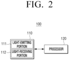
- FIG. 2 is a block diagram illustrating a configuration of an oven according to the invention.
- the oven 100 includes a sensor 110 and a processor 120.
- the sensor 110 includes a light-emitting portion 111 and a light-receiving portion 112.
- the light-emitting portion 111 outputs (or irradiate) the light of the first wavelength band and the light of the second wavelength band.
- the light-emitting portion 111 may be provided on one surface of the cooking chamber to output light to the cooking product contained in the cooking chamber.
- the light of the first wavelength band may include infrared rays.
- the light-emitting portion 111 may include an infrared LED light emitting diode (LED) for outputting infrared rays.
- the light-emitting portion 111 may include, for example, an infrared LED for outputting infrared light having a wavelength of 840 nm or 950 nm.
- the light of the second wavelength band may include visible ray.
- the light-emitting portion 111 may include an LED to output the visible ray.
- the light-emitting portion 111 may include a plurality of LEDs.
- the LEDs may output visible ray of different wavelengths from the visible ray wavelength band.
- light-emitting portion 111 may include an LED for irradiating visible ray having a wavelength of ⁇ 1, an LED for irradiating visible ray having a wavelength of ⁇ 2, LED for irradiating visible ray having a wavelength of ⁇ 3, and an LED irradiating visible ray having a wavelength of ⁇ 4.
- ⁇ 1 to ⁇ 4 may have different wavelength values within approximately 380 ⁇ 780nm.
- the light-emitting portion 111 has been described as including four LEDs. However, this is an example, and the light-emitting portion 111 may include four to eight LEDs, and in accordance with an embodiment, the light-emitting portion 111 may include more than eight LEDs.
- the oven 100 may include a focusing lens.
- the focusing lens may perform a function of adjusting the direction of light output from the light-emitting portion 111 so that the light output from the light-emitting portion 111 faces the cooking product placed in the cooking chamber.
- the light-receiving portion 112 receives light reflected from a cooking product in the oven 100.
- the light-receiving portion 112 receives the reflected or scattered light from the cooking product.
- the light-receiving portion 112 may include a plurality of light receiving modules arranged in an array format.
- the light receiving module may be a photo diode.
- the light-receiving portion 112 may include N ⁇ M photo diodes arranged in a matrix form (here, N, M is a natural number greater than or equal to 2).
- the processor 120 may control overall operations and functions of the oven 100.
- the processor 120 performs cooking of the cooking product in consideration of the size and cooking status of the cooking product in the cooking chamber.
- the processor 120 based on receiving a user command to start cooking, irradiates -may irradiate light of the first wavelength band through the light-emitting portion 111.
- the user command for the start of cooking may include various commands.
- a user may enter a cooking product into a cooking chamber and input a command (e.g., a command for selecting "chicken,” “beef,” “pork”, “pizza”, etc.) to select a type of the input cooking product into the oven 100.
- a command e.g., a command for selecting "chicken,” “beef,” “pork”, “pizza”, etc.
- the user may input a cooking product into the cooking chamber, select the type of the cooking product input by the user, and may input a command for selecting a separate button (e.g., a start button) into the oven 100.
- a separate button e.g., a start button
- the processor 120 may identify that a user command for starting cooking is input.
- the user command may be input through a display 31 or a button 32 provided in the oven 100.
- the processor 120 outputs light of the first wavelength band through a light-emitting portion 111, and when the light output from the light-emitting portion 111 is reflected from the cooking product and received at a light-receiving portion 112, the processor 120 identifies the size of the cooking product based on the received light of the first wavelength band.
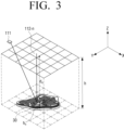
- the processor 120 may identify a distance between the plurality of light receiving modules and the cooking product based on the difference between the time of outputting the light in the first wavelength band by the light-emitting portion 111 and the time at which the light in the first wavelength band reflected from the cooking product is received by the plurality of light receiving modules.
- the sensor 110 may include a time to digital converter (not shown).
- the time-to-digital converter may start counting of the time, and when the light in the first wavelength band is received by the light-receiving portion 112, the time-to-digital converter may terminate the time counting so as to measure the time taken for the light to be reflected from the cooking product and returned, after the light is output.
- the time-to-digital converter may terminate the time counting for each light-receiving module to detect a difference between the time at which the light of the first wavelength band is outputted from the light-emitting portion 111 and the time at which the light of the first wavelength band outputted from the light-emitting portion 111 is reflected from the cooking product and is received at each of the plurality of light-receiving modules.
- the processor 120 may identify the distance between the plurality of light receiving modules and the cooking product based on the information on the time difference received from the sensor 110.
- the processor 120 may identify a distance between each of the plurality of light receiving modules and the cooking product based on a time difference measured for each light receiving module.
- ⁇ t may refer to a difference between time when light is output and received time
- c may refer to speed of light
- d may refer to a distance between a light receiving module and the cooking product.
- the processor 120 may identify the size of the cooking product based on the identified distance.
- the processor 120 may identify the size of the cooking product based on a distance between each of the plurality of light receiving modules and the cooking product and a distance between a floor surface where the cooking product is placed and the plurality of light receiving modules.
- the plurality of light receiving modules are disposed on the upper surface of the cooking chamber, and the distance between the top surface of the cooking chamber and the bottom surface on which the cooking product is placed is h.
- the distance h n of the refleced area 30 relative to the bottom surface may be h-d n .
- the processor 120 may, for each of the plurality of light-receiving modules, identify the size of the cooking product by summing all the distances between the area where the calculated light is reflected and the bottom surface.
- the processor 120 may identify the size of the cooking product through various methods capable of calculating the size of the object using the distance from the object.
- the processor 120 may determine the cooking time for the cooking product based on the type of the cooking product and the identified size of the cooking product.
- the cooking time matched with the type and size of the cooking product may be preset, and the information may be pre-stored in a memory (not used) of the oven 100.
- the cooking time may be set for each type of the cooking product, and a different cooking time may be set according to the size of the cooking product. Specifically, as the size of the cooking product is larger, a relatively longer cooking time may be set, as the size of the cooking product is larger, and a relatively shorter cooking time may be set as the size of the cooking product is smaller.
- the type of the cooking product selected according to the user command may be “chicken.”
- the processor 120 may determine a cooking time for the cooking product, depending on the size of the cooking product inserted into the cooking chamber.
- the processor 120 may determine the cooking time as ti, when the size of the cooking product falls within the range of v 1 -v 2 , determine the cooking time as t 2 , and when the size of the cooking product is greater than v 2 , may determine the cooking time as t 3 .
- v 1 ⁇ v 2 and t 1 ⁇ t 2 ⁇ t 3 may determine the cooking time as ti.
- the processor 120 may determine different cooking time according to the determined size of the cooking product, based on a user command for starting cooking.
- the cooking time may be set to be relatively long as the determined cooking product size is larger. In addition, the cooking time may be set to be relatively short as the determined size of the cooking product is smaller.
- the processor 120 may perform cooking on the cooking product based on the determined cooking time.
- the processor 120 may drive a heater to heat the cooking product to heat the cooking product during the determined cooking time.
- the processor 120 may display the determined cooking time on the display 31 provided on the oven 100.
- the processor 120 outputs light of the second wavelength band through the light-emitting portion 111 while performing the cooking for the cooking product based on the cooking time determined according to the size of the cooking product, and identifies the cooking status of the cooking product on the basis of the received light of the second wavelength band when the outputted light is reflected from the cooking product and received at the light-receiving portion 112.
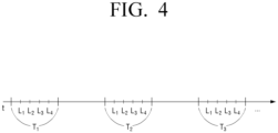
- the processor 120 may sequentially output lights of different wavelengths in the second wavelength bad through the light-emitting portion 111 in each of the plurality of time periods.
- the light-emitting portion 111 may include a plurality of LEDs that output visible ray of different wavelengths in a visible wavelength band.
- the processor 120 may sequentially output light through the plurality of LEDs in each of the plurality of time periods. At this time, the time interval between the time periods may be constant.
- the processor 120 may sequentially output light through the four LEDs in each of the plurality of time periods.
- the processor 120 may output light having a wavelength of ⁇ 1 through the first LED Li at a first time period T 1 , output light having a wavelength of ⁇ 2 through the second LED L 2 , output light having a wavelength of ⁇ 3 through the third LED L 3 , and output light having a wavelength of ⁇ 4 through the fourth LED L 4 .
- the processor 120 may output light having a wavelength of ⁇ 1 through the first LED Li at a second time period T 2 , which is after a predetermined time (e.g., after three minutes), output light having a wavelength of ⁇ 2 through the second LED L 2 , output light having a wavelength of ⁇ 3 through the third LED L 3 , and output light having a wavelength of ⁇ 4 through the fourth LED L 4 .
- the processor 120 may output light having a wavelength of ⁇ 1 through the first LED Li at a third time interval T 3 , which is after a predetermined time (e.g., after three minutes), output light having a wavelength of ⁇ 2 through the second LED L 2 , output light having a wavelength of ⁇ 3 through the third LED L 3 , and output light having a wavelength of ⁇ 4 through the fourth LED L 4 .
- the processor 120 may sequentially output visible ray of different wavelengths in each of the plurality of time periods.
- the processor 120 may identify the cooking status of the cooking product based on the intensity of the received light.
- the processor 120 may identify a cooking status of the cooking product based on a difference in intensity of light received from the plurality of light receiving modules.
- the processor 120 may identify the wavelength having the greatest difference between the intensity of light of different wavelengths received from the plurality of light receiving modules according to the light outputted from the light-emitting portion 111 in the first time period, and the intensity of light of different wavelengths received by a plurality of light receiving modules according to the light output from the light-emitting portion 111 in a subsequent time period, of the plurality of time periods, and if the difference of the identified intensity of different wavelengths is greater than or equal to a threshold value, the processor 120 may identify that the cooking of the cooking product is completed.
- the plurality of light receiving modules may include a prism or a spectral filter for separating light according to wavelength.
- the processor 120 may output visible ray of different wavelengths in the first time period, and when visible ray of different wavelengths are reflected by the cooking product and received in the plurality of light receiving modules, the processor 120 may detect the intensity of light received for each wavelength.
- the processor 120 may output visible ray of different wavelengths in the next time period, and when visible ray of different wavelengths are reflected by the cooking product and received at the plurality of light receiving modules, the processor 120 may detect the intensity of light received for each wavelength.
- the processor 120 may calculate the difference of intensity of light received by wavelengths for the first time period and the next time period.
- the processor 120 may identify the wavelength having the greatest difference and may compare the difference in intensity of the identified wavelength with a predetermined threshold value.
- the information on the predetermined threshold value may be stored in a memory (not shown) of the oven 100, and the threshold value may be set to a different value depending on the type of the cooking product. Accordingly, the processor 120 may obtain a threshold value matched with the type of the selected cooking product according to the user command, among the predetermined threshold values.
- the processor 120 may output visible ray having different wavelengths in the next time period.
- the processor 120 may detect the intensity of light received for each wavelength when the visible ray of different wavelengths outputted in the next time period is reflected by the cooking product and received at the plurality of light receiving modules.
- the processor 120 may calculate the difference of intensity of light received by wavelengths for the first time period and the next period.
- the processor 120 may identify the wavelength having the greatest difference and may compare the difference of intensity of light of the identified wavelength with a preset threshold value.
- the processor 120 may identify that cooking of the cooking product is completed.
- the processor 120 may identify the wavelength having the greatest difference and identify that cooking of the cooking product is finished, if the difference between the intensity of light of the identified wavelength is greater than or equal to a predetermined threshold value, for all the light receiving modules.
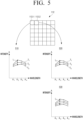
- the visible ray having a wavelength of ⁇ 1 to ⁇ 4 through the first to fourth LEDs may be assumed.
- the intensity of the visible ray of each wavelength received at the light receiving module 112-1 of the plurality of light receiving modules may be 510
- the intensity of the visible ray of each wavelength received at the light receiving module 112-2 of the plurality of light receiving modules may be 520.
- the difference il of the intensity of the visible ray having a wavelength of ⁇ 2 is largest among the wavelengths of ⁇ 1 to ⁇ 4
- the difference i 2 of the intensity of the visible ray having a wavelength of ⁇ 2 is the largest, among the wavelengths of ⁇ 1 to ⁇ 4 .
- the processor 120 may identify whether i 1 and i 2 are greater than or equal to a predetermined threshold value.
- the processor 120 may sequentially output visible ray having a wavelength of ⁇ 1 to ⁇ 4 through the first to fourth LEDs at a time period T 4 , which is the next time period.
- the processor 120 may calculate a difference between intensity of a visible ray having a wavelength of ⁇ 1 to ⁇ 4 received from the light receiving module 112-2 at a time period T 1 and intensity of a visible ray line having a wavelength of ⁇ 1 to ⁇ 4 received from the light receiving module 112-2 at time period T 4 .
- the processor 120 may identify whether i 3 is greater than or equal to a preset threshold value.
- the processor 120 may identify that the cooking of the cooking product is completed when the difference between the intensity of light of the identified wavelength is greater than or equal to a predetermined threshold value, through this method.
- the reason of identifying the cooking status of the cooking product is as shown below.
- a property of the cooking product may change.
- the cooking product may have a relatively high absorption rate with respect to light of a specific wavelength. Accordingly, according to an embodiment, it is identified whether the cooking status of the cooking product, that is, the object is cooked, depending on the degree of absorption of the cooking product with specific wavelength of light.
- the above method is merely an example, and the processor 120 may identify the cooking status of the cooking product through various methods.
- the processor 120 may output visible ray having different wavelengths in a time period, and may detect the intensity of light received for each wavelength when the visible ray of different wavelengths are reflected by the cooking product and received at the plurality of light receiving modules.
- the processor 120 may sum all the detected intensities of light and then normalize the summed value.
- the processor 120 may calculate a difference between a normalized value and a value pre-stored in a memory (not shown) of the oven 100, and identify whether an absolute value of the calculated difference is less than or equal to a predetermined threshold value.
- information on a pre-stored value and a predetermined threshold value may be pre-stored in a memory (not shown) of the oven 100, and these values may be set to different values depending on the type of the cooking product. Accordingly, among the pre-stored value and the predetermined threshold value, a threshold value matched with the type of the selected cooking product may be obtained according to the user command.
- the processor 120 may identify that the cooking of the cooking product has been completed.
- the processor 120 may output visible ray having different wavelengths in the next time period.
- the processor 120 may detect the intensity of light received for each wavelength when the visible ray of different wavelengths outputted in the next time period is reflected by the cooking product and received at the plurality of light receiving modules.
- the processor 120 may calculate the absolute value of the difference by performing the above-described process for the next time period, and may identify whether the calculated absolute value is less than or equal to a predetermined threshold value.
- the processor 10 may identify the cooking status of the cooking product.
- the processor 120 may stop the cooking of the cooking product.
- the processor 120 may stop driving of the heater that has been driven for heating the cooking product.
- the processor 120 may display information indicating that the cooking has been completed on the display 31 provided in the oven 100, or may output a specific sound through a speaker (not shown) of the oven 100.
- different cooking times may be determined depending on the size of the cooking product, and the time at which the cooking is terminated according to the cooking status of the cooking product may be determined while the cooking is being performed.
- the user may optimally cook the cooking product without monitoring the cooking process.
- the invention it is possible to identify both the size and cooking status of the cooking product using one sensor including a light-emitting portion for outputting light and a light-receiving portion for receiving light without a separate additional sensor.
- FIG. 6 is a block diagram illustrating a configuration of an oven in detail according to an embodiment.
- the oven 100 may include the sensor 110, the processor 120, an input interface 130, a memory 140, and a speaker 150.
- the components shown in FIG. 6 may be controlled by the processor 120. Since the sensor 110 and the processor 120 shown in FIG. 6 have been described in FIG. 2 , a description thereof will be omitted.
- the input interface 130 may receive a user command to control the electronic device 100.
- the input interface 130 may include a display 31 implemented as a touch screen together with the touch panel to receive a user touch, and a button 32 for receiving a user operation.
- the display 31 may display various screens. For example, the display 31 may display information on a cooking time and the like.
- the example of the input interface 130 of FIG. 6 is merely exemplary, and the input interface 130 may include a microphone (not shown) for receiving a user voice and other input devices (e.g., a keyboard, a mouse, a motion inputter, etc.), or the like.
- a microphone not shown
- other input devices e.g., a keyboard, a mouse, a motion inputter, etc.
- the memory 140 may store various data for operating the oven 100.
- the memory 140 may store data, or the like, related to at least one another component of the oven 100.
- the memory 140 may be a non-volatile memory, a volatile memory, a flash memory, a hard disk drive (HDD), or a solid state drive (SSD).
- the memory 140 may be accessed by the processor 120, and read/write/modify/update data by the processor 130 may be performed.
- the term memory may include the memory 140, the ROM (not shown), RAM (not shown) in the processor 120, or a memory card (not shown) (e.g., a micro secure digital (SD) card, a memory stick) mounted in the electronic device 100.
- SD micro secure digital
- the speaker 150 is configured to output various notification sound or voice messages as well as audio data. When the cooking of the cooking product in the oven 100 is completed, the speaker 150 may output audio to inform the user of the completion of the cooking.
- FIG. 7 is a flowchart illustrating a method of describing a cooking method ofan oven according to an embodiment of the invention.
- the light-emitting portion and the light-receiving portion of the oven 2. are included.
- the light in the first wavelength band is output through the light-emitting portion in operation S710.
- the light in the wavelength band may be infrared rays.
- a size of the cooking product is identified based on the received light in the first wavelength band in operation S720.
- the light in the second wavelength band is output through the light-emitting portion while the cooking product is being cooked based on a cooking time determined according to the identified size of the cooking product in operation S730.
- the light in the second wavelength band may be visible ray.
- a cooking status of the cooking product is identified based on the received light in the second wavelength band in operation S740.
- the cooking product is cooked based on the identified cooking status in operation S750.
- the light-receiving portion may include a plurality of light-receiving modules arranged in a form of an array.
- a distance between the plurality of light receiving modules and the cooking product may be identified, and a size of the cooking product may be identified based on the identified distance.
- the different cooking times may be determined according to the identified size of the cooking product for a type of a cooking product selected based on a user command to initiate the cooking, and the greater the identified size of the cooking product is, the longer the cooking time is.
- lights of different wavelengths in the second wavelength band may be sequentially output through the light-emitting portion in each of a plurality of time periods, and based on the lights of different wavelengths being reflected from the cooking product and received by the plurality of light receiving modules, a cooking status of the cooking product may be identified based on an intensity of the received light.
- the cooking status of the cooking product may be identified based on the difference of intensity of light received at a plurality of light receiving modules.
- the wavelength having the greatest difference between the intensity of light of different wavelengths received from the plurality of light-receiving modules and the intensity of the light output from the light-emitting portion may be identified, and if the difference between the intensity of the identified wavelength of light is greater than or equal to a predetermined threshold value, it may be identified that the cooking of the cooking product has been completed.
- cooking of the cooking product may be stopped.
- a specific method of identifying the size and cooking status of the cooking product may be identified using the light of the first wavelength band and light of the second wavelength band, and performing cooking for the cooking product has been described above.
- unit or “module” used in the disclosure includes units consisting of hardware, software, or firmware, and is used interchangeably with terms such as, for example, logic, logic blocks, parts, or circuits.
- a “unit” or “module” may be an integrally constructed component or a minimum unit or part thereof that performs one or more functions.
- the module may be configured as an application-specific integrated circuit (ASIC).
- ASIC application-specific integrated circuit
- a machine is a device which may call instructions from the storage medium and operate according to the called instructions, and may include an electronic device (example: oven 100) of the embodiments.
- the processor may perform a function corresponding to the instructions directly or by using other components under the control of the processor.
- the instructions may include a code generated by a compiler or a code executable by an interpreter.
- a machine-readable storage medium may be provided in the form of a non-transitory storage medium.
- non-transitory only denotes that a storage medium does not include a signal but is tangible, and does not distinguish the case in which a data is semi-permanently stored in a storage medium from the case in which a data is temporarily stored in a storage medium.
- the method according to various embodiments disclosed herein may be provided in a computer program product.
- a computer program product may be exchanged between a seller and a purchaser as a commodity.
- a computer program product may be distributed in the form of a machine-readable storage medium (e.g., compact disc read only memory (CD-ROM)) or distributed online through an application store (e.g. PlayStore TM ) directly between two user devices (e.g., smartphones).
- an application store e.g. PlayStore TM
- at least a portion of the computer program product may be stored temporarily or at least temporarily in a storage medium such as a manufacturer's server, a server of an application store, or a memory of a relay server.
Landscapes
- Engineering & Computer Science (AREA)
- Physics & Mathematics (AREA)
- Chemical & Material Sciences (AREA)
- General Physics & Mathematics (AREA)
- Combustion & Propulsion (AREA)
- General Engineering & Computer Science (AREA)
- Mechanical Engineering (AREA)
- General Health & Medical Sciences (AREA)
- Health & Medical Sciences (AREA)
- Immunology (AREA)
- Pathology (AREA)
- Spectroscopy & Molecular Physics (AREA)
- Life Sciences & Earth Sciences (AREA)
- Biochemistry (AREA)
- Analytical Chemistry (AREA)
- Electric Stoves And Ranges (AREA)
- Electric Ovens (AREA)
Claims (15)
- Ofen (100), umfassend:einen Sensor (110), der einen lichtemittierenden Abschnitt (111) zum Ausgeben von Licht in einem ersten Wellenlängenband und Licht in einem zweiten Wellenlängenband und einen lichtempfangenden Abschnitt (112) zum Empfangen von Licht, das von einem Kochprodukt in dem Ofen (100) reflektiert wird, umfasst;einen Prozessor (120), der konfiguriert ist, um:
basierend darauf, dass ein Benutzerbefehl zum Einleiten des Kochens eingegeben wird, das Licht in dem ersten Wellenlängenband durch den lichtemittierenden Abschnitt (111) auszugeben, und basierend darauf, dass das von dem lichtemittierenden Abschnitt (111) ausgegebene Licht vom Kochprodukt reflektiert und von dem lichtempfangenden Abschnitt (112) empfangen wird, eine Größe des Kochprodukts auf der Grundlage des empfangenen Lichts in dem ersten Wellenlängenband zu identifizieren, dadurch gekennzeichnet, dass der Prozessor ferner konfiguriert ist zum:Ausgeben des Lichts in dem zweiten Wellenlängenband durch den lichtemittierenden Abschnitt (111), während das Kochprodukt auf der Grundlage einer Kochzeit gekocht wird, die gemäß der identifizierten Größe des Kochprodukts bestimmt wird, und basierend darauf, dass das ausgegebene Licht von dem Kochprodukt reflektiert und von dem lichtempfangenden Abschnitt (112) empfangen wird, Identifizieren eines Kochzustands des Kochprodukts auf der Grundlage des empfangenen Lichts in dem zweiten Wellenlängenband, undKochen des Kochprodukts auf der Grundlage des identifizierten Kochzustands. - Ofen (100) nach Anspruch 1, wobei das Licht im ersten Wellenlängenband Infrarotstrahlen sind und das Licht im zweiten Wellenlängenband sichtbare Strahlen sind.
- Ofen (100) nach Anspruch 1, wobei der lichtempfangende Abschnitt (112) eine Vielzahl von Lichtempfangsmodulen umfasst, die in Form eines Arrays angeordnet sind.
- Ofen (100) nach Anspruch 3, wobei der Prozessor (120) ferner konfiguriert ist, um:
basierend auf einer Differenz zwischen einer Zeit, zu der das Licht in dem ersten Wellenlängenband von dem lichtemittierenden Abschnitt (111) ausgegeben wird, und einer Zeit, zu der das Licht in dem ersten Wellenlängenband von dem Kochprodukt reflektiert und von der Vielzahl von Lichtempfangsmodulen empfangen wird, einen Abstand zwischen der Vielzahl von Lichtempfangsmodulen und dem Kochprodukt zu identifizieren, und eine Größe des Kochprodukts basierend auf dem identifizierten Abstand zu identifizieren. - Ofen (100) nach Anspruch 1, wobei der Prozessor (120) ferner so konfiguriert ist, dass er unterschiedliche Kochzeiten entsprechend der identifizierten Größe des Kochprodukts für einen Typ eines Kochprodukts bestimmt, der auf der Grundlage eines Benutzerbefehls zum Einleiten des Kochvorgangs ausgewählt wurde, und
wobei, je größer die identifizierte Größe des Kochprodukts ist, desto länger die Kochzeit ist. - Ofen (100) nach Anspruch 3, wobei der Prozessor (120) ferner so konfiguriert ist, dass er in jeder von mehreren Zeitperioden durch den lichtemittierenden Abschnitt (111) nacheinander Licht unterschiedlicher Wellenlängen im zweiten Wellenlängenband ausgibt und basierend darauf, dass das Lichter unterschiedlicher Wellenlängen vom Kochprodukt reflektiert und von den mehreren Lichtempfangsmodulen empfangen wird, einen Kochzustand des Kochprodukts auf der Grundlage einer Intensität des empfangenen Lichts identifiziert.
- Ofen (100) nach Anspruch 6, wobei der Prozessor (120) ferner so konfiguriert ist, dass er den Kochzustand des Kochprodukts auf der Grundlage einer Differenz der Intensität des von den mehreren Lichtempfangsmodulen empfangenen Lichts identifiziert.
- Ofen (100) nach Anspruch 7, wobei der Prozessor (120) ferner konfiguriert ist zum:
Identifizieren einer Wellenlänge mit dem größten Unterschied zwischen einer Intensität von Licht unterschiedlicher Wellenlängen, das von der Vielzahl von Lichtempfangsmodulen gemäß dem von dem lichtemittierenden Abschnitt (111) ausgegebenen Licht in einer ersten Zeitperiode empfangen wird, und einer Intensität von Licht unterschiedlicher Wellenlängen, das von der Vielzahl von Lichtempfangsmodulen gemäß dem vom lichtemittierenden Abschnitt (111) ausgegebenen Licht in einer nachfolgenden Zeitperiode empfangen wird, unter der Vielzahl von Zeitpunkten, und basierend darauf, dass die Differenz der Intensität des Lichts der identifizierten Wellenlänge größer oder gleich einem voreingestellten Schwellenwert ist, Identifizieren, dass das Kochen des Kochprodukts abgeschlossen ist. - Ofen (100) nach Anspruch 1, wobei der Prozessor (120) ferner so konfiguriert ist, dass er auf der Grundlage des Identifizierens, dass das Kochen des Kochprodukts abgeschlossen ist, gemäß dem identifizierten Kochzustand, das Kochen des Kochprodukts beendet.
- Verfahren zum Kochen durch einen Ofen (100), der einen Sensor (110) mit einem lichtemittierenden Abschnitt (111) und einem lichtempfangenden Abschnitt (112) aufweist, wobei das Verfahren umfasst:basierend darauf, dass ein Benutzerbefehl zum Einleiten des Kochens eingegeben wird, Ausgeben des Lichts in einem ersten Wellenlängenband durch den lichtemittierenden Abschnitt (111);basierend darauf, dass das von dem lichtemittierenden Abschnitt (111) ausgegebene Licht von dem Kochprodukt reflektiert und von dem lichtempfangenden Abschnitt (112) empfangen wird, Identifizieren einer Größe des Kochprodukts basierend auf dem empfangenen Licht in dem ersten Wellenlängenband; wobei das Verfahren gekennzeichnet ist durch:Ausgeben des Lichts in einem zweiten Wellenlängenband durch den lichtemittierenden Abschnitt (111), während das Kochprodukt auf der Grundlage einer Kochzeit, die entsprechend der identifizierten Größe des Kochprodukts bestimmt wird, gekocht wird;basierend darauf, dass das ausgegebene Licht von dem Kochprodukt reflektiert und von dem lichtempfangenden Abschnitt (112) empfangen wird, Identifizieren eines Kochzustands des Kochprodukts basierend auf dem empfangenen Licht in dem zweiten Wellenlängenband; undKochen des Kochprodukts auf der Grundlage des identifizierten Kochzustands.
- Verfahren nach Anspruch 10, wobei das Licht im ersten Wellenlängenband Infrarotstrahlen sind und das Licht im zweiten Wellenlängenband sichtbare Strahlen sind.
- Verfahren nach Anspruch 10, wobei der lichtempfangende Abschnitt (112) eine Vielzahl von Lichtempfangsmodulen umfasst, die in Form eines Arrays angeordnet sind.
- Verfahren nach Anspruch 12, wobei das Identifizieren einer Größe des Kochprodukts das Identifizieren, auf der Grundlage einer Differenz zwischen einer Zeit, zu der das Licht in dem ersten Wellenlängenband von dem lichtemittierenden Abschnitt (111) ausgegeben wird, und einer Zeit, zu der das Licht in dem ersten Wellenlängenband von dem Kochprodukt reflektiert und von der Vielzahl von Lichtempfangsmodulen empfangen wird, eines Abstands zwischen der Vielzahl von Lichtempfangsmodulen und dem Kochprodukt und das Identifizieren einer Größe des Kochprodukts auf der Grundlage des identifizierten Abstands umfasst.
- Verfahren nach Anspruch 10, ferner umfassend:Bestimmen unterschiedlicher Kochzeiten entsprechend der identifizierten Größe des Kochprodukts für einen Typ eines Kochprodukts, der auf der Grundlage eines Benutzerbefehls zur Einleitung des Kochvorgangs ausgewählt wurde,wobei, je größer die identifizierte Größe des Kochprodukts ist, desto länger die Kochzeit ist.
- Verfahren nach Anspruch 12, wobei das Identifizieren des Kochzustands das sequentielle Ausgeben von Licht unterschiedlicher Wellenlängen im zweiten Wellenlängenband durch den lichtemittierenden Abschnitt (111) in jeder von mehreren Zeitperioden und, basierend darauf, dass das Licht unterschiedlicher Wellenlängen von dem Kochprodukt reflektiert und von den mehreren Lichtempfangsmodulen empfangen wird, das Identifizieren eines Kochzustands des Kochprodukts basierend auf einer Intensität des empfangenen Lichts umfasst.
Applications Claiming Priority (2)
| Application Number | Priority Date | Filing Date | Title |
|---|---|---|---|
| KR1020190013841A KR102614945B1 (ko) | 2019-02-01 | 2019-02-01 | 오븐 및 그의 조리 방법 |
| PCT/KR2020/001483 WO2020159281A1 (ko) | 2019-02-01 | 2020-01-31 | 오븐 및 그의 조리 방법 |
Publications (3)
| Publication Number | Publication Date |
|---|---|
| EP3848637A1 EP3848637A1 (de) | 2021-07-14 |
| EP3848637A4 EP3848637A4 (de) | 2021-12-22 |
| EP3848637B1 true EP3848637B1 (de) | 2023-08-16 |
Family
ID=71841190
Family Applications (1)
| Application Number | Title | Priority Date | Filing Date |
|---|---|---|---|
| EP20747646.6A Active EP3848637B1 (de) | 2019-02-01 | 2020-01-31 | Ofen und kochverfahren dafür |
Country Status (5)
| Country | Link |
|---|---|
| US (1) | US12196429B2 (de) |
| EP (1) | EP3848637B1 (de) |
| KR (1) | KR102614945B1 (de) |
| CN (1) | CN113227658B (de) |
| WO (1) | WO2020159281A1 (de) |
Family Cites Families (30)
| Publication number | Priority date | Publication date | Assignee | Title |
|---|---|---|---|---|
| IT1204216B (it) * | 1986-02-10 | 1989-03-01 | Zanussi Zeltron Inst | Dispositivo per controllare lo stato di cottura di un articolo |
| JPH05340548A (ja) * | 1992-06-05 | 1993-12-21 | Toshiba Corp | 加熱調理器 |
| JPH05346235A (ja) * | 1992-06-16 | 1993-12-27 | Toshiba Corp | 調理装置 |
| JP2627730B2 (ja) * | 1993-09-23 | 1997-07-09 | エルジー電子株式会社 | 電子レンジの自動整合装置 |
| KR0133029B1 (ko) * | 1993-09-28 | 1998-04-15 | 구자홍 | 전자렌지의 자동 정합장치 |
| KR950011940A (ko) | 1993-10-26 | 1995-05-16 | 배순훈 | 전자렌지의 조리물 형상 인식장치 |
| JPH07248120A (ja) * | 1994-03-11 | 1995-09-26 | Hitachi Ltd | 電磁誘導処理装置 |
| DE4416762A1 (de) * | 1994-05-14 | 1995-11-23 | Krieg Gunther | Verfahren und Vorrichtung zur kontinuierlichen Messung des Bräunungsgrades bei Back- Koch- Röstprozessen in voll- oder halbautomatischen Back- Koch- Röstsystemen |
| KR100239242B1 (ko) * | 1994-09-16 | 2000-03-02 | 니시무로 타이죠 | 가열조리기 |
| KR100206759B1 (ko) | 1994-12-10 | 1999-07-01 | 구자홍 | 전자레인지의 균일가열장치 |
| KR960041890A (ko) | 1995-05-16 | 1996-12-19 | 구자홍 | 자동 조리장치 |
| JPH11281333A (ja) * | 1995-08-07 | 1999-10-15 | Komatsu Ltd | 物体の距離計測装置および形状計測装置 |
| KR19980015200A (ko) | 1996-08-20 | 1998-05-25 | 김영귀 | 자동차용 코너링센서(cornering sensor)의 가변 감지장치 |
| KR19980015200U (ko) * | 1996-09-06 | 1998-06-25 | 김광호 | 가스오븐렌지의 그릴조리장치 |
| KR19980050563A (ko) | 1996-12-21 | 1998-09-15 | 구자홍 | 전자레인지의 음식물 판단장치 |
| AU3641799A (en) * | 1998-04-14 | 1999-11-01 | Quadlux, Inc. | Lightwave oven and method of cooking therewith using conventional cooking recipes |
| JP2000012211A (ja) * | 1998-06-23 | 2000-01-14 | Toshiba Corp | 電子レンジ |
| JP3846205B2 (ja) * | 2001-02-28 | 2006-11-15 | 松下電器産業株式会社 | 高周波加熱装置 |
| KR101976463B1 (ko) | 2012-08-29 | 2019-05-09 | 엘지전자 주식회사 | 3차원 영상 생성 장치 및 방법 |
| JP6051067B2 (ja) * | 2013-02-06 | 2016-12-21 | シャープ株式会社 | 加熱調理器 |
| DE102013102293A1 (de) | 2013-03-07 | 2014-09-11 | Rational Ag | Verfahren zur Erkennung von Lebensmitteln |
| DE102013102295A1 (de) * | 2013-03-07 | 2014-09-11 | Rational Ag | Verfahren zur Anpassung eines Lebensmittel-Garprozesses |
| WO2015101992A2 (en) | 2014-01-03 | 2015-07-09 | Verifood, Ltd. | Spectrometry systems, methods, and applications |
| DE102014114901A1 (de) * | 2014-10-14 | 2016-04-14 | Frima International Ag | Gargerät sowie Verfahren zur Erfassung eines Prozessparameters eines Garprozesses |
| US9644847B2 (en) | 2015-05-05 | 2017-05-09 | June Life, Inc. | Connected food preparation system and method of use |
| KR102414251B1 (ko) * | 2015-10-13 | 2022-06-29 | 삼성전자주식회사 | 조리 장치 및 이의 제어 방법 |
| US20180172510A1 (en) * | 2016-12-08 | 2018-06-21 | Verifood, Ltd. | Spectrometry system applications |
| KR102628210B1 (ko) | 2017-01-26 | 2024-01-24 | 삼성전자주식회사 | 식품 관리를 위한 전자 장치 및 이의 제어 방법 |
| DE102017206056A1 (de) * | 2017-04-10 | 2018-10-11 | BSH Hausgeräte GmbH | Betreiben eines Gargeräts |
| CN111279792A (zh) * | 2017-09-18 | 2020-06-12 | 国际制造技术咨询有限两合公司 | 监控系统以及食物制备系统 |
-
2019
- 2019-02-01 KR KR1020190013841A patent/KR102614945B1/ko active Active
-
2020
- 2020-01-31 EP EP20747646.6A patent/EP3848637B1/de active Active
- 2020-01-31 CN CN202080007427.8A patent/CN113227658B/zh active Active
- 2020-01-31 WO PCT/KR2020/001483 patent/WO2020159281A1/ko not_active Ceased
- 2020-01-31 US US17/421,117 patent/US12196429B2/en active Active
Also Published As
| Publication number | Publication date |
|---|---|
| EP3848637A1 (de) | 2021-07-14 |
| WO2020159281A1 (ko) | 2020-08-06 |
| US20220120444A1 (en) | 2022-04-21 |
| KR20200095893A (ko) | 2020-08-11 |
| CN113227658A (zh) | 2021-08-06 |
| CN113227658B (zh) | 2023-11-21 |
| EP3848637A4 (de) | 2021-12-22 |
| KR102614945B1 (ko) | 2023-12-19 |
| US12196429B2 (en) | 2025-01-14 |
Similar Documents
| Publication | Publication Date | Title |
|---|---|---|
| CN111148944B (zh) | 自动烹饪设备和方法 | |
| AU2017276748B2 (en) | Method for operating a food processor | |
| US11241118B2 (en) | Food processor comprising at least one processor device and one monitoring device | |
| EP3131410B1 (de) | Kochprozesssteuerung | |
| KR102371752B1 (ko) | 가전 기기 및 그의 제어방법 | |
| EP3168602A1 (de) | Lebensmittelproduktanalysevorrichtung | |
| JP2005043045A (ja) | バーコードを利用した調理装置 | |
| US11206949B1 (en) | High power density toaster | |
| EP3148386B1 (de) | Verfahren und kochvorrichtung zur steuerung eines kochverfahrens für nahrungsmittel | |
| KR20220073638A (ko) | 조리 기기 및 그 제어 방법 | |
| CN104955187A (zh) | 电磁加热装置及其控制组件和控制方法 | |
| JP2009098015A (ja) | 物体のカロリー測定装置 | |
| CN105595789A (zh) | 检测是否加水的方法和装置及烹饪器具和烹饪控制方法 | |
| CN109310244A (zh) | 用于掼奶油的自动控制功能 | |
| KR102914042B1 (ko) | 후드 장치, 후드 장치에 부착 가능한 온도 센싱 장치 및 온도 센싱 방법 | |
| EP3848637A1 (de) | Ofen und kochverfahren dafür | |
| JP2021103038A (ja) | 調理機器 | |
| CN115371092B (zh) | 烟灶联动的烟机的控制方法、系统、烟机及存储介质 | |
| US20240029337A1 (en) | Employing Controlled Illumination for Hyperspectral or Multispectral Imaging of Food in an Appliance | |
| KR20230130968A (ko) | 조리 상태를 제공하는 조리 장치 및 방법 | |
| CN115371094B (zh) | 烟灶联动的烟机的控制方法、系统、烟机及存储介质 | |
| WO2023223876A1 (ja) | 加熱調理器 | |
| WO2013054664A1 (ja) | 情報処理装置、情報処理方法、プログラム、及び電子機器 | |
| CN115371093B (zh) | 烟灶联动的烟机的控制方法、系统、烟机及存储介质 | |
| JPH0755154A (ja) | 加熱調理装置 |
Legal Events
| Date | Code | Title | Description |
|---|---|---|---|
| STAA | Information on the status of an ep patent application or granted ep patent |
Free format text: STATUS: THE INTERNATIONAL PUBLICATION HAS BEEN MADE |
|
| PUAI | Public reference made under article 153(3) epc to a published international application that has entered the european phase |
Free format text: ORIGINAL CODE: 0009012 |
|
| STAA | Information on the status of an ep patent application or granted ep patent |
Free format text: STATUS: REQUEST FOR EXAMINATION WAS MADE |
|
| 17P | Request for examination filed |
Effective date: 20210408 |
|
| AK | Designated contracting states |
Kind code of ref document: A1 Designated state(s): AL AT BE BG CH CY CZ DE DK EE ES FI FR GB GR HR HU IE IS IT LI LT LU LV MC MK MT NL NO PL PT RO RS SE SI SK SM TR |
|
| A4 | Supplementary search report drawn up and despatched |
Effective date: 20211118 |
|
| RIC1 | Information provided on ipc code assigned before grant |
Ipc: G01N 21/25 20060101ALI20211112BHEP Ipc: G01B 11/02 20060101ALI20211112BHEP Ipc: F24C 3/12 20060101ALI20211112BHEP Ipc: F24C 7/08 20060101AFI20211112BHEP |
|
| DAV | Request for validation of the european patent (deleted) | ||
| DAX | Request for extension of the european patent (deleted) | ||
| GRAP | Despatch of communication of intention to grant a patent |
Free format text: ORIGINAL CODE: EPIDOSNIGR1 |
|
| STAA | Information on the status of an ep patent application or granted ep patent |
Free format text: STATUS: GRANT OF PATENT IS INTENDED |
|
| INTG | Intention to grant announced |
Effective date: 20230414 |
|
| GRAS | Grant fee paid |
Free format text: ORIGINAL CODE: EPIDOSNIGR3 |
|
| GRAA | (expected) grant |
Free format text: ORIGINAL CODE: 0009210 |
|
| STAA | Information on the status of an ep patent application or granted ep patent |
Free format text: STATUS: THE PATENT HAS BEEN GRANTED |
|
| AK | Designated contracting states |
Kind code of ref document: B1 Designated state(s): AL AT BE BG CH CY CZ DE DK EE ES FI FR GB GR HR HU IE IS IT LI LT LU LV MC MK MT NL NO PL PT RO RS SE SI SK SM TR |
|
| RAP3 | Party data changed (applicant data changed or rights of an application transferred) |
Owner name: SAMSUNG ELECTRONICS CO., LTD. |
|
| RIN1 | Information on inventor provided before grant (corrected) |
Inventor name: NOH, TAEGYOON Inventor name: CHOI, JUNHOE Inventor name: HAN, JEONGSU |
|
| REG | Reference to a national code |
Ref country code: CH Ref legal event code: EP |
|
| REG | Reference to a national code |
Ref country code: DE Ref legal event code: R096 Ref document number: 602020015898 Country of ref document: DE |
|
| REG | Reference to a national code |
Ref country code: IE Ref legal event code: FG4D |
|
| REG | Reference to a national code |
Ref country code: LT Ref legal event code: MG9D |
|
| REG | Reference to a national code |
Ref country code: NL Ref legal event code: MP Effective date: 20230816 |
|
| REG | Reference to a national code |
Ref country code: AT Ref legal event code: MK05 Ref document number: 1600388 Country of ref document: AT Kind code of ref document: T Effective date: 20230816 |
|
| PG25 | Lapsed in a contracting state [announced via postgrant information from national office to epo] |
Ref country code: GR Free format text: LAPSE BECAUSE OF FAILURE TO SUBMIT A TRANSLATION OF THE DESCRIPTION OR TO PAY THE FEE WITHIN THE PRESCRIBED TIME-LIMIT Effective date: 20231117 |
|
| PG25 | Lapsed in a contracting state [announced via postgrant information from national office to epo] |
Ref country code: IS Free format text: LAPSE BECAUSE OF FAILURE TO SUBMIT A TRANSLATION OF THE DESCRIPTION OR TO PAY THE FEE WITHIN THE PRESCRIBED TIME-LIMIT Effective date: 20231216 |
|
| PG25 | Lapsed in a contracting state [announced via postgrant information from national office to epo] |
Ref country code: SE Free format text: LAPSE BECAUSE OF FAILURE TO SUBMIT A TRANSLATION OF THE DESCRIPTION OR TO PAY THE FEE WITHIN THE PRESCRIBED TIME-LIMIT Effective date: 20230816 Ref country code: RS Free format text: LAPSE BECAUSE OF FAILURE TO SUBMIT A TRANSLATION OF THE DESCRIPTION OR TO PAY THE FEE WITHIN THE PRESCRIBED TIME-LIMIT Effective date: 20230816 Ref country code: PT Free format text: LAPSE BECAUSE OF FAILURE TO SUBMIT A TRANSLATION OF THE DESCRIPTION OR TO PAY THE FEE WITHIN THE PRESCRIBED TIME-LIMIT Effective date: 20231218 Ref country code: NO Free format text: LAPSE BECAUSE OF FAILURE TO SUBMIT A TRANSLATION OF THE DESCRIPTION OR TO PAY THE FEE WITHIN THE PRESCRIBED TIME-LIMIT Effective date: 20231116 Ref country code: NL Free format text: LAPSE BECAUSE OF FAILURE TO SUBMIT A TRANSLATION OF THE DESCRIPTION OR TO PAY THE FEE WITHIN THE PRESCRIBED TIME-LIMIT Effective date: 20230816 Ref country code: LV Free format text: LAPSE BECAUSE OF FAILURE TO SUBMIT A TRANSLATION OF THE DESCRIPTION OR TO PAY THE FEE WITHIN THE PRESCRIBED TIME-LIMIT Effective date: 20230816 Ref country code: LT Free format text: LAPSE BECAUSE OF FAILURE TO SUBMIT A TRANSLATION OF THE DESCRIPTION OR TO PAY THE FEE WITHIN THE PRESCRIBED TIME-LIMIT Effective date: 20230816 Ref country code: IS Free format text: LAPSE BECAUSE OF FAILURE TO SUBMIT A TRANSLATION OF THE DESCRIPTION OR TO PAY THE FEE WITHIN THE PRESCRIBED TIME-LIMIT Effective date: 20231216 Ref country code: HR Free format text: LAPSE BECAUSE OF FAILURE TO SUBMIT A TRANSLATION OF THE DESCRIPTION OR TO PAY THE FEE WITHIN THE PRESCRIBED TIME-LIMIT Effective date: 20230816 Ref country code: GR Free format text: LAPSE BECAUSE OF FAILURE TO SUBMIT A TRANSLATION OF THE DESCRIPTION OR TO PAY THE FEE WITHIN THE PRESCRIBED TIME-LIMIT Effective date: 20231117 Ref country code: FI Free format text: LAPSE BECAUSE OF FAILURE TO SUBMIT A TRANSLATION OF THE DESCRIPTION OR TO PAY THE FEE WITHIN THE PRESCRIBED TIME-LIMIT Effective date: 20230816 Ref country code: AT Free format text: LAPSE BECAUSE OF FAILURE TO SUBMIT A TRANSLATION OF THE DESCRIPTION OR TO PAY THE FEE WITHIN THE PRESCRIBED TIME-LIMIT Effective date: 20230816 |
|
| PG25 | Lapsed in a contracting state [announced via postgrant information from national office to epo] |
Ref country code: PL Free format text: LAPSE BECAUSE OF FAILURE TO SUBMIT A TRANSLATION OF THE DESCRIPTION OR TO PAY THE FEE WITHIN THE PRESCRIBED TIME-LIMIT Effective date: 20230816 |
|
| PG25 | Lapsed in a contracting state [announced via postgrant information from national office to epo] |
Ref country code: ES Free format text: LAPSE BECAUSE OF FAILURE TO SUBMIT A TRANSLATION OF THE DESCRIPTION OR TO PAY THE FEE WITHIN THE PRESCRIBED TIME-LIMIT Effective date: 20230816 |
|
| PG25 | Lapsed in a contracting state [announced via postgrant information from national office to epo] |
Ref country code: SM Free format text: LAPSE BECAUSE OF FAILURE TO SUBMIT A TRANSLATION OF THE DESCRIPTION OR TO PAY THE FEE WITHIN THE PRESCRIBED TIME-LIMIT Effective date: 20230816 Ref country code: RO Free format text: LAPSE BECAUSE OF FAILURE TO SUBMIT A TRANSLATION OF THE DESCRIPTION OR TO PAY THE FEE WITHIN THE PRESCRIBED TIME-LIMIT Effective date: 20230816 Ref country code: ES Free format text: LAPSE BECAUSE OF FAILURE TO SUBMIT A TRANSLATION OF THE DESCRIPTION OR TO PAY THE FEE WITHIN THE PRESCRIBED TIME-LIMIT Effective date: 20230816 Ref country code: EE Free format text: LAPSE BECAUSE OF FAILURE TO SUBMIT A TRANSLATION OF THE DESCRIPTION OR TO PAY THE FEE WITHIN THE PRESCRIBED TIME-LIMIT Effective date: 20230816 Ref country code: DK Free format text: LAPSE BECAUSE OF FAILURE TO SUBMIT A TRANSLATION OF THE DESCRIPTION OR TO PAY THE FEE WITHIN THE PRESCRIBED TIME-LIMIT Effective date: 20230816 Ref country code: CZ Free format text: LAPSE BECAUSE OF FAILURE TO SUBMIT A TRANSLATION OF THE DESCRIPTION OR TO PAY THE FEE WITHIN THE PRESCRIBED TIME-LIMIT Effective date: 20230816 Ref country code: SK Free format text: LAPSE BECAUSE OF FAILURE TO SUBMIT A TRANSLATION OF THE DESCRIPTION OR TO PAY THE FEE WITHIN THE PRESCRIBED TIME-LIMIT Effective date: 20230816 |
|
| REG | Reference to a national code |
Ref country code: DE Ref legal event code: R097 Ref document number: 602020015898 Country of ref document: DE |
|
| PLBE | No opposition filed within time limit |
Free format text: ORIGINAL CODE: 0009261 |
|
| STAA | Information on the status of an ep patent application or granted ep patent |
Free format text: STATUS: NO OPPOSITION FILED WITHIN TIME LIMIT |
|
| 26N | No opposition filed |
Effective date: 20240517 |
|
| PG25 | Lapsed in a contracting state [announced via postgrant information from national office to epo] |
Ref country code: IT Free format text: LAPSE BECAUSE OF FAILURE TO SUBMIT A TRANSLATION OF THE DESCRIPTION OR TO PAY THE FEE WITHIN THE PRESCRIBED TIME-LIMIT Effective date: 20230816 Ref country code: SI Free format text: LAPSE BECAUSE OF FAILURE TO SUBMIT A TRANSLATION OF THE DESCRIPTION OR TO PAY THE FEE WITHIN THE PRESCRIBED TIME-LIMIT Effective date: 20230816 |
|
| PG25 | Lapsed in a contracting state [announced via postgrant information from national office to epo] |
Ref country code: MC Free format text: LAPSE BECAUSE OF FAILURE TO SUBMIT A TRANSLATION OF THE DESCRIPTION OR TO PAY THE FEE WITHIN THE PRESCRIBED TIME-LIMIT Effective date: 20230816 |
|
| PG25 | Lapsed in a contracting state [announced via postgrant information from national office to epo] |
Ref country code: MC Free format text: LAPSE BECAUSE OF FAILURE TO SUBMIT A TRANSLATION OF THE DESCRIPTION OR TO PAY THE FEE WITHIN THE PRESCRIBED TIME-LIMIT Effective date: 20230816 |
|
| REG | Reference to a national code |
Ref country code: CH Ref legal event code: PL |
|
| PG25 | Lapsed in a contracting state [announced via postgrant information from national office to epo] |
Ref country code: LU Free format text: LAPSE BECAUSE OF NON-PAYMENT OF DUE FEES Effective date: 20240131 |
|
| GBPC | Gb: european patent ceased through non-payment of renewal fee |
Effective date: 20240131 |
|
| PG25 | Lapsed in a contracting state [announced via postgrant information from national office to epo] |
Ref country code: LU Free format text: LAPSE BECAUSE OF NON-PAYMENT OF DUE FEES Effective date: 20240131 |
|
| PG25 | Lapsed in a contracting state [announced via postgrant information from national office to epo] |
Ref country code: GB Free format text: LAPSE BECAUSE OF NON-PAYMENT OF DUE FEES Effective date: 20240131 |
|
| PG25 | Lapsed in a contracting state [announced via postgrant information from national office to epo] |
Ref country code: BE Free format text: LAPSE BECAUSE OF NON-PAYMENT OF DUE FEES Effective date: 20240131 |
|
| PG25 | Lapsed in a contracting state [announced via postgrant information from national office to epo] |
Ref country code: FR Free format text: LAPSE BECAUSE OF NON-PAYMENT OF DUE FEES Effective date: 20240131 |
|
| PG25 | Lapsed in a contracting state [announced via postgrant information from national office to epo] |
Ref country code: CH Free format text: LAPSE BECAUSE OF NON-PAYMENT OF DUE FEES Effective date: 20240131 |
|
| PG25 | Lapsed in a contracting state [announced via postgrant information from national office to epo] |
Ref country code: GB Free format text: LAPSE BECAUSE OF NON-PAYMENT OF DUE FEES Effective date: 20240131 Ref country code: FR Free format text: LAPSE BECAUSE OF NON-PAYMENT OF DUE FEES Effective date: 20240131 Ref country code: CH Free format text: LAPSE BECAUSE OF NON-PAYMENT OF DUE FEES Effective date: 20240131 Ref country code: BE Free format text: LAPSE BECAUSE OF NON-PAYMENT OF DUE FEES Effective date: 20240131 |
|
| REG | Reference to a national code |
Ref country code: BE Ref legal event code: MM Effective date: 20240131 |
|
| PG25 | Lapsed in a contracting state [announced via postgrant information from national office to epo] |
Ref country code: BG Free format text: LAPSE BECAUSE OF FAILURE TO SUBMIT A TRANSLATION OF THE DESCRIPTION OR TO PAY THE FEE WITHIN THE PRESCRIBED TIME-LIMIT Effective date: 20230816 |
|
| PG25 | Lapsed in a contracting state [announced via postgrant information from national office to epo] |
Ref country code: BG Free format text: LAPSE BECAUSE OF FAILURE TO SUBMIT A TRANSLATION OF THE DESCRIPTION OR TO PAY THE FEE WITHIN THE PRESCRIBED TIME-LIMIT Effective date: 20230816 |
|
| PG25 | Lapsed in a contracting state [announced via postgrant information from national office to epo] |
Ref country code: IE Free format text: LAPSE BECAUSE OF NON-PAYMENT OF DUE FEES Effective date: 20240131 |
|
| PG25 | Lapsed in a contracting state [announced via postgrant information from national office to epo] |
Ref country code: IE Free format text: LAPSE BECAUSE OF NON-PAYMENT OF DUE FEES Effective date: 20240131 |
|
| PG25 | Lapsed in a contracting state [announced via postgrant information from national office to epo] |
Ref country code: CY Free format text: LAPSE BECAUSE OF FAILURE TO SUBMIT A TRANSLATION OF THE DESCRIPTION OR TO PAY THE FEE WITHIN THE PRESCRIBED TIME-LIMIT; INVALID AB INITIO Effective date: 20200131 |
|
| PG25 | Lapsed in a contracting state [announced via postgrant information from national office to epo] |
Ref country code: HU Free format text: LAPSE BECAUSE OF FAILURE TO SUBMIT A TRANSLATION OF THE DESCRIPTION OR TO PAY THE FEE WITHIN THE PRESCRIBED TIME-LIMIT; INVALID AB INITIO Effective date: 20200131 |
|
| PG25 | Lapsed in a contracting state [announced via postgrant information from national office to epo] |
Ref country code: TR Free format text: LAPSE BECAUSE OF FAILURE TO SUBMIT A TRANSLATION OF THE DESCRIPTION OR TO PAY THE FEE WITHIN THE PRESCRIBED TIME-LIMIT Effective date: 20230816 |
|
| PGFP | Annual fee paid to national office [announced via postgrant information from national office to epo] |
Ref country code: DE Payment date: 20251222 Year of fee payment: 7 |