EP3829366B1 - Cartridge-basierte hitze nicht brennen verdampfer - Google Patents
Cartridge-basierte hitze nicht brennen verdampfer Download PDFInfo
- Publication number
- EP3829366B1 EP3829366B1 EP19753543.8A EP19753543A EP3829366B1 EP 3829366 B1 EP3829366 B1 EP 3829366B1 EP 19753543 A EP19753543 A EP 19753543A EP 3829366 B1 EP3829366 B1 EP 3829366B1
- Authority
- EP
- European Patent Office
- Prior art keywords
- cartridge
- vaporizer
- source substance
- heating element
- passageway
- Prior art date
- Legal status (The legal status is an assumption and is not a legal conclusion. Google has not performed a legal analysis and makes no representation as to the accuracy of the status listed.)
- Active
Links
Images


Classifications
-
- A—HUMAN NECESSITIES
- A24—TOBACCO; CIGARS; CIGARETTES; SIMULATED SMOKING DEVICES; SMOKERS' REQUISITES
- A24F—SMOKERS' REQUISITES; MATCH BOXES; SIMULATED SMOKING DEVICES
- A24F40/00—Electrically operated smoking devices; Component parts thereof; Manufacture thereof; Maintenance or testing thereof; Charging means specially adapted therefor
- A24F40/40—Constructional details, e.g. connection of cartridges and battery parts
- A24F40/46—Shape or structure of electric heating means
-
- A—HUMAN NECESSITIES
- A24—TOBACCO; CIGARS; CIGARETTES; SIMULATED SMOKING DEVICES; SMOKERS' REQUISITES
- A24B—MANUFACTURE OR PREPARATION OF TOBACCO FOR SMOKING OR CHEWING; TOBACCO; SNUFF
- A24B15/00—Chemical features or treatment of tobacco; Tobacco substitutes, e.g. in liquid form
- A24B15/10—Chemical features of tobacco products or tobacco substitutes
- A24B15/16—Chemical features of tobacco products or tobacco substitutes of tobacco substitutes
- A24B15/167—Chemical features of tobacco products or tobacco substitutes of tobacco substitutes in liquid or vaporisable form, e.g. liquid compositions for electronic cigarettes
-
- A—HUMAN NECESSITIES
- A24—TOBACCO; CIGARS; CIGARETTES; SIMULATED SMOKING DEVICES; SMOKERS' REQUISITES
- A24F—SMOKERS' REQUISITES; MATCH BOXES; SIMULATED SMOKING DEVICES
- A24F40/00—Electrically operated smoking devices; Component parts thereof; Manufacture thereof; Maintenance or testing thereof; Charging means specially adapted therefor
- A24F40/40—Constructional details, e.g. connection of cartridges and battery parts
- A24F40/42—Cartridges or containers for inhalable precursors
-
- A—HUMAN NECESSITIES
- A61—MEDICAL OR VETERINARY SCIENCE; HYGIENE
- A61M—DEVICES FOR INTRODUCING MEDIA INTO, OR ONTO, THE BODY; DEVICES FOR TRANSDUCING BODY MEDIA OR FOR TAKING MEDIA FROM THE BODY; DEVICES FOR PRODUCING OR ENDING SLEEP OR STUPOR
- A61M11/00—Sprayers or atomisers specially adapted for therapeutic purposes
- A61M11/04—Sprayers or atomisers specially adapted for therapeutic purposes operated by the vapour pressure of the liquid to be sprayed or atomised
- A61M11/041—Sprayers or atomisers specially adapted for therapeutic purposes operated by the vapour pressure of the liquid to be sprayed or atomised using heaters
- A61M11/042—Sprayers or atomisers specially adapted for therapeutic purposes operated by the vapour pressure of the liquid to be sprayed or atomised using heaters electrical
-
- A—HUMAN NECESSITIES
- A61—MEDICAL OR VETERINARY SCIENCE; HYGIENE
- A61M—DEVICES FOR INTRODUCING MEDIA INTO, OR ONTO, THE BODY; DEVICES FOR TRANSDUCING BODY MEDIA OR FOR TAKING MEDIA FROM THE BODY; DEVICES FOR PRODUCING OR ENDING SLEEP OR STUPOR
- A61M15/00—Inhalators
- A61M15/06—Inhaling appliances shaped like cigars, cigarettes or pipes
-
- A—HUMAN NECESSITIES
- A61—MEDICAL OR VETERINARY SCIENCE; HYGIENE
- A61M—DEVICES FOR INTRODUCING MEDIA INTO, OR ONTO, THE BODY; DEVICES FOR TRANSDUCING BODY MEDIA OR FOR TAKING MEDIA FROM THE BODY; DEVICES FOR PRODUCING OR ENDING SLEEP OR STUPOR
- A61M16/00—Devices for influencing the respiratory system of patients by gas treatment, e.g. ventilators; Tracheal tubes
-
- H—ELECTRICITY
- H05—ELECTRIC TECHNIQUES NOT OTHERWISE PROVIDED FOR
- H05B—ELECTRIC HEATING; ELECTRIC LIGHT SOURCES NOT OTHERWISE PROVIDED FOR; CIRCUIT ARRANGEMENTS FOR ELECTRIC LIGHT SOURCES, IN GENERAL
- H05B3/00—Ohmic-resistance heating
- H05B3/0019—Circuit arrangements
-
- H—ELECTRICITY
- H05—ELECTRIC TECHNIQUES NOT OTHERWISE PROVIDED FOR
- H05B—ELECTRIC HEATING; ELECTRIC LIGHT SOURCES NOT OTHERWISE PROVIDED FOR; CIRCUIT ARRANGEMENTS FOR ELECTRIC LIGHT SOURCES, IN GENERAL
- H05B3/00—Ohmic-resistance heating
- H05B3/20—Heating elements having extended surface area substantially in a two-dimensional plane, e.g. plate-heater
- H05B3/22—Heating elements having extended surface area substantially in a two-dimensional plane, e.g. plate-heater non-flexible
- H05B3/24—Heating elements having extended surface area substantially in a two-dimensional plane, e.g. plate-heater non-flexible heating conductor being self-supporting
-
- H—ELECTRICITY
- H05—ELECTRIC TECHNIQUES NOT OTHERWISE PROVIDED FOR
- H05B—ELECTRIC HEATING; ELECTRIC LIGHT SOURCES NOT OTHERWISE PROVIDED FOR; CIRCUIT ARRANGEMENTS FOR ELECTRIC LIGHT SOURCES, IN GENERAL
- H05B3/00—Ohmic-resistance heating
- H05B3/20—Heating elements having extended surface area substantially in a two-dimensional plane, e.g. plate-heater
- H05B3/34—Heating elements having extended surface area substantially in a two-dimensional plane, e.g. plate-heater flexible, e.g. heating nets or webs
-
- A—HUMAN NECESSITIES
- A24—TOBACCO; CIGARS; CIGARETTES; SIMULATED SMOKING DEVICES; SMOKERS' REQUISITES
- A24F—SMOKERS' REQUISITES; MATCH BOXES; SIMULATED SMOKING DEVICES
- A24F40/00—Electrically operated smoking devices; Component parts thereof; Manufacture thereof; Maintenance or testing thereof; Charging means specially adapted therefor
- A24F40/20—Devices using solid inhalable precursors
-
- A—HUMAN NECESSITIES
- A61—MEDICAL OR VETERINARY SCIENCE; HYGIENE
- A61M—DEVICES FOR INTRODUCING MEDIA INTO, OR ONTO, THE BODY; DEVICES FOR TRANSDUCING BODY MEDIA OR FOR TAKING MEDIA FROM THE BODY; DEVICES FOR PRODUCING OR ENDING SLEEP OR STUPOR
- A61M16/00—Devices for influencing the respiratory system of patients by gas treatment, e.g. ventilators; Tracheal tubes
- A61M16/0003—Accessories therefor, e.g. sensors, vibrators, negative pressure
- A61M2016/0015—Accessories therefor, e.g. sensors, vibrators, negative pressure inhalation detectors
- A61M2016/0018—Accessories therefor, e.g. sensors, vibrators, negative pressure inhalation detectors electrical
- A61M2016/0021—Accessories therefor, e.g. sensors, vibrators, negative pressure inhalation detectors electrical with a proportional output signal, e.g. from a thermistor
-
- A—HUMAN NECESSITIES
- A61—MEDICAL OR VETERINARY SCIENCE; HYGIENE
- A61M—DEVICES FOR INTRODUCING MEDIA INTO, OR ONTO, THE BODY; DEVICES FOR TRANSDUCING BODY MEDIA OR FOR TAKING MEDIA FROM THE BODY; DEVICES FOR PRODUCING OR ENDING SLEEP OR STUPOR
- A61M16/00—Devices for influencing the respiratory system of patients by gas treatment, e.g. ventilators; Tracheal tubes
- A61M16/0003—Accessories therefor, e.g. sensors, vibrators, negative pressure
- A61M2016/0027—Accessories therefor, e.g. sensors, vibrators, negative pressure pressure meter
-
- A—HUMAN NECESSITIES
- A61—MEDICAL OR VETERINARY SCIENCE; HYGIENE
- A61M—DEVICES FOR INTRODUCING MEDIA INTO, OR ONTO, THE BODY; DEVICES FOR TRANSDUCING BODY MEDIA OR FOR TAKING MEDIA FROM THE BODY; DEVICES FOR PRODUCING OR ENDING SLEEP OR STUPOR
- A61M2205/00—General characteristics of the apparatus
- A61M2205/35—Communication
- A61M2205/3576—Communication with non implanted data transmission devices, e.g. using external transmitter or receiver
- A61M2205/3592—Communication with non implanted data transmission devices, e.g. using external transmitter or receiver using telemetric means, e.g. radio or optical transmission
-
- A—HUMAN NECESSITIES
- A61—MEDICAL OR VETERINARY SCIENCE; HYGIENE
- A61M—DEVICES FOR INTRODUCING MEDIA INTO, OR ONTO, THE BODY; DEVICES FOR TRANSDUCING BODY MEDIA OR FOR TAKING MEDIA FROM THE BODY; DEVICES FOR PRODUCING OR ENDING SLEEP OR STUPOR
- A61M2205/00—General characteristics of the apparatus
- A61M2205/36—General characteristics of the apparatus related to heating or cooling
- A61M2205/3653—General characteristics of the apparatus related to heating or cooling by Joule effect, i.e. electric resistance
-
- A—HUMAN NECESSITIES
- A61—MEDICAL OR VETERINARY SCIENCE; HYGIENE
- A61M—DEVICES FOR INTRODUCING MEDIA INTO, OR ONTO, THE BODY; DEVICES FOR TRANSDUCING BODY MEDIA OR FOR TAKING MEDIA FROM THE BODY; DEVICES FOR PRODUCING OR ENDING SLEEP OR STUPOR
- A61M2205/00—General characteristics of the apparatus
- A61M2205/82—Internal energy supply devices
- A61M2205/8206—Internal energy supply devices battery-operated
-
- H—ELECTRICITY
- H05—ELECTRIC TECHNIQUES NOT OTHERWISE PROVIDED FOR
- H05B—ELECTRIC HEATING; ELECTRIC LIGHT SOURCES NOT OTHERWISE PROVIDED FOR; CIRCUIT ARRANGEMENTS FOR ELECTRIC LIGHT SOURCES, IN GENERAL
- H05B2203/00—Aspects relating to Ohmic resistive heating covered by group H05B3/00
- H05B2203/002—Heaters using a particular layout for the resistive material or resistive elements
- H05B2203/003—Heaters using a particular layout for the resistive material or resistive elements using serpentine layout
-
- H—ELECTRICITY
- H05—ELECTRIC TECHNIQUES NOT OTHERWISE PROVIDED FOR
- H05B—ELECTRIC HEATING; ELECTRIC LIGHT SOURCES NOT OTHERWISE PROVIDED FOR; CIRCUIT ARRANGEMENTS FOR ELECTRIC LIGHT SOURCES, IN GENERAL
- H05B2203/00—Aspects relating to Ohmic resistive heating covered by group H05B3/00
- H05B2203/002—Heaters using a particular layout for the resistive material or resistive elements
- H05B2203/007—Heaters using a particular layout for the resistive material or resistive elements using multiple electrically connected resistive elements or resistive zones
-
- H—ELECTRICITY
- H05—ELECTRIC TECHNIQUES NOT OTHERWISE PROVIDED FOR
- H05B—ELECTRIC HEATING; ELECTRIC LIGHT SOURCES NOT OTHERWISE PROVIDED FOR; CIRCUIT ARRANGEMENTS FOR ELECTRIC LIGHT SOURCES, IN GENERAL
- H05B2203/00—Aspects relating to Ohmic resistive heating covered by group H05B3/00
- H05B2203/013—Heaters using resistive films or coatings
-
- H—ELECTRICITY
- H05—ELECTRIC TECHNIQUES NOT OTHERWISE PROVIDED FOR
- H05B—ELECTRIC HEATING; ELECTRIC LIGHT SOURCES NOT OTHERWISE PROVIDED FOR; CIRCUIT ARRANGEMENTS FOR ELECTRIC LIGHT SOURCES, IN GENERAL
- H05B2203/00—Aspects relating to Ohmic resistive heating covered by group H05B3/00
- H05B2203/021—Heaters specially adapted for heating liquids
-
- H—ELECTRICITY
- H05—ELECTRIC TECHNIQUES NOT OTHERWISE PROVIDED FOR
- H05B—ELECTRIC HEATING; ELECTRIC LIGHT SOURCES NOT OTHERWISE PROVIDED FOR; CIRCUIT ARRANGEMENTS FOR ELECTRIC LIGHT SOURCES, IN GENERAL
- H05B2203/00—Aspects relating to Ohmic resistive heating covered by group H05B3/00
- H05B2203/03—Heaters specially adapted for heating hand held tools
-
- H—ELECTRICITY
- H05—ELECTRIC TECHNIQUES NOT OTHERWISE PROVIDED FOR
- H05B—ELECTRIC HEATING; ELECTRIC LIGHT SOURCES NOT OTHERWISE PROVIDED FOR; CIRCUIT ARRANGEMENTS FOR ELECTRIC LIGHT SOURCES, IN GENERAL
- H05B2203/00—Aspects relating to Ohmic resistive heating covered by group H05B3/00
- H05B2203/035—Electrical circuits used in resistive heating apparatus
Definitions
- the subject matter described herein relates to vaporizer devices, including a system for heating vaporizable material to generate an inhalable aerosol.
- Vaporizing devices including electronic vaporizers or e-vaporizer devices, allow the delivery of vapor containing one or more active ingredients to a user by inhalation of the vapor.
- Electronic vaporizer devices are gaining increasing popularity both for prescriptive medical use, in delivering medicaments, and for consumption of tobacco and other plant-based smokeable materials, such as cannabis, including solid (e.g., loose-leaf) materials, solid/liquid (e.g., suspensions, liquid-coated) materials, wax extracts, and prefilled pods (cartridges, wrapped containers, etc.) of such materials.
- Electronic vaporizer devices in particular may be portable, self-contained, and convenient for use.
- vaporizer cartridges configured to heat vaporizable material (e.g., plant material such as tobacco leaves and/or parts of tobacco leaves) require higher temperatures for the inner tobacco regions to reach the minimum required temperature for vaporization. As a result, burning the vaporizable material at these high peak temperatures can produce toxic bi-products (e.g., chemical elements or chemical compounds).
- vaporizable material e.g., plant material such as tobacco leaves and/or parts of tobacco leaves
- Patent document WO2017/207582A1 discloses an aerosol-generating device having a cartridge which is refillable.
- Patent document US2017/164657A1 discloses an aerosol-forming cartridge for use in an electrically operated aerosol-generating system.
- the cartridge may include a chamber configured to contain a non-liquid vaporizable material.
- the cartridge may include a heating element.
- the heating element may include an electrically resistive material and may be configured to vaporize the vaporizable material by delivery of heat to the vaporizable material, wherein at least a portion of the heating element may define a part of the chamber and/or may be contained within the chamber.
- the cartridge may include a cartridge contact in electrical communication with the electrically resistive material.
- the cartridge contact may be configured to couple to a vaporizer contact positioned proximate to a cartridge coupling feature to allow electrical power to pass from the vaporizer device through the electrically resistive material.
- the electrical power may cause heating of the electrically resistive material and the vaporizable material to result in generation of an aerosol for inhalation by a user.
- the heating element may include the cartridge contact.
- the cartridge may include a sheet of thermally conductive, electrically resistive material.
- the sheet of thermally conductive, electrically resistive material may include at least one of a flexible material, a deformable material, and a rigid material.
- the sheet of thermally conductive, electrically resistive material may include at least one perforation.
- the sheet of thermally conductive, electrically resistive material may include at least one extension extending away from at least one of a top surface of the sheet of thermally conductive, electrically resistive material and a bottom surface of the sheet of thermally conductive, electrically resistive material.
- the sheet of thermally conductive, electrically resistive material may include a first area having a first density of perforations and a second area having a second density of perforations that is greater than a first density of perforations.
- the heating element may include a non-electrically conductive area.
- the heating element may include a flexible printed circuit including the electrically resistive material traced on a flexible material, and wherein the traced electrically resistive material may form a plurality of series heaters.
- the plurality of series heaters may be positioned in parallel.
- the heating element may include a flexible material with the electrically resistive material extending along a length of the flexible material.
- the cartridge may include a housing.
- the housing may include a non-electrically conductive material and may contain at least a part of the chamber.
- the vaporizable material may include nicotine.
- a system for a generating an inhalable aerosol may include the cartridge.
- the cartridge may include a chamber configured to contain a non-liquid vaporizable material.
- the cartridge may include a heating element.
- the heating element may include an electrically resistive material and may be configured to vaporize the vaporizable material by delivery of heat to the vaporizable material, wherein at least a portion of the heating element defines a part of the chamber and/or may be contained within the chamber.
- the cartridge may include a cartridge contact in electrical communication with the electrically resistive material.
- the cartridge contact may be configured to couple to a vaporizer contact positioned proximate to a cartridge coupling feature to allow electrical power to pass from the vaporizer device through the electrically resistive material.
- the electrical power may cause heating of the electrically resistive material and the vaporizable material to result in generation of an aerosol for inhalation by a user
- the system may include a device body.
- the device body may include a cartridge receptacle for receiving the cartridge.
- the device body may include a vaporizer contact configured to mate with the cartridge contact when the cartridge is inserted into the cartridge receptacle to provide an electrically conductive pathway between a power source in the device body and the heating element of the cartridge.
- a method for generating an inhalable aerosol may include coupling a cartridge contact of a vaporizer cartridge to a vaporizer contact of a vaporizer device body to provide an electrically conductive pathway between a power source of the vaporizer device body and a heating element of the vaporizer cartridge.
- the electrically conductive pathway may allow the power source to cause heating of an electrically resistive material of the heating element and the vaporizable material contained in a chamber of the cartridge.
- the method may include heating the heating element to vaporize the vaporizable material and form an aerosol for inhalation, wherein the heating element defines at least a part of the chamber and/or is contained within the chamber of the vaporizer cartridge.
- Implementations of the current subject matter include devices relating to vaporizing one or more materials for inhalation by a user.
- vaporizer cartridges such as single-use disposable cartridges, having a variety of heater element embodiments are described herein.
- Such vaporizer cartridges can be configured for use with non-liquid vaporizable material, such as loose-leaf tobacco.
- the various heater element embodiments described herein can improve the efficiency and quality of heating of the vaporizable material, such as heating the vaporizable material within an optimal heating range.
- Such optimal heating range includes a temperature that is hot enough to vaporize the vaporizable material into an aerosol for inhalation, while also heating below a temperature that produces harmful or potentially harmful byproducts.
- the heating elements described herein can achieve the optimal heating range at a rate that allows a user to have an enjoyable user experience (e.g., not have to wait a long time for the heating element to reach a temperature in the optimal heating range, etc.).
- the vaporizer cartridges including such heating elements can be cost effectively manufactured, thereby making them economically feasible as single-use disposable cartridges.
- Various vaporizer cartridges and heating elements including one or more of the above features are described in greater detail below.
- vaporizable material used with a vaporizer may optionally be provided within a cartridge (e.g., a part of the vaporizer that contains the vaporizable material or a source substance that includes the vaporizable material in a reservoir or other container and that can be refillable when empty or disposable in favor of a new cartridge containing additional vaporizable material of a same or different type).
- a vaporizer may be a cartridgeusing vaporizer, a cartridge-less vaporizer, or a multi-use vaporizer capable of use with or without a cartridge.
- a multi-use vaporizer may include a heating chamber (e.g., an oven) configured to receive a source substance containing a vaporizable material directly in the heating chamber and also to receive a vaporizer cartridge 120 or other replaceable device having a reservoir, a volume, or the like for at least partially containing a usable amount of a source substance containing or including the vaporizable material.
- a heating chamber e.g., an oven
- a vaporizer cartridge 120 or other replaceable device having a reservoir, a volume, or the like for at least partially containing a usable amount of a source substance containing or including the vaporizable material.
- a vaporizer may be configured for use with a solid vaporizable material, which may include a plant material that emits some part of the plant material as the vaporizable material (e.g., such that some part of the plant material remains as waste after the vaporizable material is emitted for inhalation by a user) or optionally can be a solid form of the vaporizable material itself (e.g., a "wax”) such that all of the solid material can eventually be vaporized for inhalation.
- a solid vaporizable material may include a plant material that emits some part of the plant material as the vaporizable material (e.g., such that some part of the plant material remains as waste after the vaporizable material is emitted for inhalation by a user) or optionally can be a solid form of the vaporizable material itself (e.g., a "wax”) such that all of the solid material can eventually be vaporized for inhalation.
- a vaporizer 100 typically includes a power source 112 (such as a battery which may be a rechargeable battery), and a controller 104 (e.g., a processor, circuitry, etc. capable of executing logic) for controlling delivery of heat to a heating element to cause a vaporizable material to be converted from a condensed form (e.g., a solid, a liquid, a solution, a suspension, a part of an at least partially unprocessed plant material, etc.) to the gas phase.
- the controller 104 may be part of one or more printed circuit boards (PCBs) consistent with certain implementations of the current subject matter.
- the condensed form is typically a plant-based material, at least part of which is a vaporizable material capable of being converted to vapor under heating of the plant-based material.
- At least some of the gas-phase vaporizable material may condense to form particulate matter in at least a partial local equilibrium with the gas phase as part of an aerosol, which can form some or all of an inhalable dose provided by the vaporizer 100 for a given puff or draw on the vaporizer.
- the interplay between gas and condensed phases in an aerosol generated by a vaporizer can be complex and dynamic, as factors such as ambient temperature, relative humidity, chemistry, flow conditions in airflow paths (both inside the vaporizer and in the airways of a human or other animal), mixing of the gas-phase or aerosol-phase vaporizable material with other air streams, etc. may affect one or more physical parameters of an aerosol.
- the inhalable dose may exist predominantly in the gas phase (i.e., formation of condensed phase particles may be very limited).
- vaporizers consistent with implementations of the current subject matter may also or alternatively be configured to create an inhalable dose of gas-phase and/or aerosol-phase vaporizable material via heating of a non-liquid source substance containing or including a vaporizable material, such as for example a solid-phase vaporizable material or plant material (e.g., tobacco leaves and/or parts of tobacco leaves) containing the vaporizable material.
- a heating element may be part of or otherwise incorporated into or in thermal contact with the walls of an oven or other heating chamber into which the non-liquid source substance that contains or includes a vaporizable material is placed.
- a heating element or elements may be used to heat air passing through or past the non-liquid source substance to cause convective heating of the non-liquid vaporizable material.
- a heating element or elements may be disposed in intimate contact with plant material such that direct thermal conduction heating of the source substance occurs from within a mass of the source substance (e.g., as opposed to only by conduction inward from walls of an oven).
- Such non-liquid vaporizable materials may be used with cartridge using or cartridge less vaporizers.
- the heating element can be or include one or more of a conductive heater, a radiative heater, and a convective heater.
- a resistive heating element which can be constructed of or at least include a material (e.g., a metal or alloy, for example a nickel-chromium alloy, or a non-metallic resistor) configured to dissipate electrical power in the form of heat when electrical current is passed through one or more resistive segments of the heating element.
- an atomizer can include a heating element that includes resistive coil or other heating element wrapped around, positioned within, integrated into a bulk shape of, pressed into thermal contact with, or otherwise arranged to deliver heat to a mass of a source substance (e.g., plant basedsubstance such as tobacco) that contains the vaporizable material.
- a source substance e.g., plant basedsubstance such as tobacco
- source substance generally refers to the part of a plant-based material (or other condensed form of a plant material or other material that may release vaporizable material without being burned) that contains vaporizable materials that are converted to vapor and/or aerosol for inhalation.
- Other heating element, and/or atomizer assembly configurations are also possible, as discussed further below.
- the heating element may be activated (e.g., a controller, which is optionally part of a vaporizer body as discussed below, may cause current to pass from the power source through a circuit including the resistive heating element, which is optionally part of a vaporizer cartridge as discussed below), in association with a user puffing (e.g., drawing, inhaling, etc.) on a mouthpiece of the vaporizer to cause air to flow from an air inlet, along an airflow path that passes the heating element and an associated mass of the source substance, optionally through one or more condensation areas or chambers, to an air outlet in the mouthpiece. Incoming air passing along the airflow path passes over, through, etc.
- a controller which is optionally part of a vaporizer body as discussed below, may cause current to pass from the power source through a circuit including the resistive heating element, which is optionally part of a vaporizer cartridge as discussed below
- a user puffing e.g., drawing, inhaling, etc.
- gas phase vaporizable material is entrained into the air.
- the entrained gas-phase vaporizable material may condense as it passes through the remainder of the airflow path such that an inhalable dose of the vaporizable material in an aerosol form can be delivered from the air outlet (e.g., in a mouthpiece for inhalation by a user).
- Activation of the heating element may be caused by automatic detection of the puff based on one or more of signals generated by one or more sensors 113, such as for example a pressure sensor or sensors disposed to detect pressure along the airflow path relative to ambient pressure (or optionally to measure changes in absolute pressure), one or more motion sensors of the vaporizer, one or more flow sensors of the vaporizer, a capacitive lip sensor of the vaporizer; in response to detection of interaction of a user with one or more input devices 116 (e.g., buttons or other tactile control devices of the vaporizer 100), receipt of signals from a computing device in communication with the vaporizer; and/or via other approaches for determining that a puff is occurring or imminent.
- sensors 113 such as for example a pressure sensor or sensors disposed to detect pressure along the airflow path relative to ambient pressure (or optionally to measure changes in absolute pressure), one or more motion sensors of the vaporizer, one or more flow sensors of the vaporizer, a capacitive lip sensor of the vaporizer; in response to detection of
- a vaporizer consistent with implementations of the current subject matter may be configured to connect (e.g., wirelessly or via a wired connection) to a computing device (or optionally two or more devices) in communication with the vaporizer.
- the controller 104 may include communication hardware 105.
- the controller 104 may also include a memory 108.
- a computing device can be a component of a vaporizer system that also includes the vaporizer 100, and can include its own communication hardware, which can establish a wireless communication channel with the communication hardware 105 of the vaporizer 100.
- a computing device used as part of a vaporizer system may include a general-purpose computing device (e.g., a smartphone, a tablet, a personal computer, some other portable device such as a smartwatch, or the like) that executes software to produce a user interface for enabling a user of the device to interact with a vaporizer.
- a general-purpose computing device e.g., a smartphone, a tablet, a personal computer, some other portable device such as a smartwatch, or the like
- a user interface for enabling a user of the device to interact with a vaporizer.
- such a device used as part of a vaporizer system can be a dedicated piece of hardware such as a remote control or other wireless or wired device having one or more physical or soft (e.g., configurable on a screen or other display device and selectable via user interaction with a touch-sensitive screen or some other input device like a mouse, pointer, trackball, cursor buttons, or the like) interface controls.
- the vaporizer can also include one or more output 117 features or devices for providing information to the user.
- the output 117 can include one or more light emitting diodes (LED) configured to provide feedback to a user based on a status and/or mode of operation of the vaporizer 100.
- LED light emitting diodes
- a computing device that is part of a vaporizer system as defined above can be used for any of one or more functions, such as controlling dosing (e.g., dose monitoring, dose setting, dose limiting, user tracking, etc.), controlling sessioning (e.g., session monitoring, session setting, session limiting, user tracking, etc.), controlling nicotine delivery (e.g., switching between nicotine and non-nicotine vaporizable material, adjusting an amount of nicotine delivered, etc.), obtaining locational information (e.g., location of other users, retailer/commercial venue locations, vaping locations, relative or absolute location of the vaporizer itself, etc.), vaporizer personalization (e.g., naming the vaporizer, locking/password protecting the vaporizer, adjusting one or more parental controls, associating the vaporizer with a user group, registering the vaporizer with a manufacturer or warranty maintenance organization, etc.), engaging in social activities (e.g., games, social media communications, interacting with one or more groups, etc.) with other users,
- the terms “sessioning”, “session”, “vaporizer session,” or “vapor session,” are used generically to refer to a period devoted to the use of the vaporizer.
- the period can include a time period, a number of doses, an amount of vaporizable material, and/or the like.
- a computing device provides signals related to activation of the resistive heating element
- the computing device executes one or more computer instructions sets to provide a user interface and underlying data handling.
- detection by the computing device of user interaction with one or more user interface elements can cause the computing device to signal the vaporizer 100 to activate the heating element, either to a full operating temperature for creation of an inhalable dose of vapor/aerosol.
- Other functions of the vaporizer may be controlled by interaction of a user with a user interface on a computing device in communication with the vaporizer.
- the temperature of a resistive heating element of a vaporizer may depend on a number of factors, including an amount of electrical power delivered to the resistive heating element and/or a duty cycle at which the electrical power is delivered, conductive heat transfer to other parts of the electronic vaporizer and/or to the environment, latent heat losses due to vaporization of a vaporizable material from the atomizer as a whole, and convective heat losses due to airflow (e.g., air moving across the heating element or the atomizer as a whole when a user inhales on the electronic vaporizer).
- a vaporizer may, in some implementations of the current subject matter, make use of signals from a pressure sensor to determine when a user is inhaling.
- the pressure sensor can be positioned in the airflow path and/or can be connected (e.g., by a passageway or other path) to an airflow path connecting an inlet for air to enter the device and an outlet via which the user inhales the resulting vapor and/or aerosol such that the pressure sensor experiences pressure changes concurrently with air passing through the vaporizer device from the air inlet to the air outlet.
- the heating element may be activated in association with a user's puff, for example by automatic detection of the puff, for example by the pressure sensor detecting a pressure change in the airflow path.
- the pressure sensor (as well as any other sensors 113) can be positioned on or coupled (e.g., electrically or electronically connected, either physically or via a wireless connection) to the controller 104 (e.g., a printed circuit board assembly or other type of circuit board).
- the controller 104 e.g., a printed circuit board assembly or other type of circuit board.
- the seal 121 which can be a gasket, may be configured to at least partially surround the pressure sensor such that connections of the pressure sensor to internal circuitry of the vaporizer are separated from a part of the pressure sensor exposed to the airflow path.
- the seal 121 may also separate parts of one or more electrical connections between a vaporizer body 110 and a vaporizer cartridge 120.
- Such arrangements of a seal 121 in a vaporizer 100 can be helpful in mitigating against potentially disruptive impacts on vaporizer components resulting from interactions with environmental factors such as water in the vapor or liquid phases, other fluids such as the vaporizable material, etc. and/or to reduce escape of air from the designed airflow path in the vaporizer.
- Unwanted air, liquid or other fluid passing and/or contacting circuitry of the vaporizer can cause various unwanted effects, such as alter pressure readings, and/or can result in the buildup of unwanted material, such as moisture, the vaporizable material, etc.
- Leaks in the seal 121 can also result in a user inhaling air that has passed over parts of the vaporizer device containing or constructed of materials that may not be desirable to be inhaled.
- a general class of vaporizers that have recently gained popularity includes a vaporizer body 110 that includes a controller 104, a power source 112 (e.g., battery), one more sensors 113, charging contacts, a seal 121, and a cartridge receptacle 118 configured to receive a vaporizer cartridge 120 for coupling with the vaporizer body 110 through one or more of a variety of attachment structures.
- vaporizer cartridge 120 includes a mouthpiece for delivering an inhalable dose to a user.
- the vaporizer body 110 can include an atomizer having a heating element 150, or alternatively, the heating element 150 can be part of the vaporizer cartridge 120.
- a vaporizer cartridge 120 may include a mass of a source substance that is processed and formed to have direct contact with parts of one or more resistive heating elements, and such a vaporizer cartridge 120 may be configured to be coupled mechanically and electrically to a vaporizer body 110 that includes a processor, a power source 112, and electrical contacts for connecting to corresponding cartridge contacts 124 for completing a circuit with the one or more resistive heating elements.
- the vaporizer 100 may include electrical connection features (e.g., means for completing a circuit) for completing a circuit that includes the controller 104 (e.g., a printed circuit board, a microcontroller, or the like), the power source 112, and the heating element 150.
- electrical connection features e.g., means for completing a circuit
- the controller 104 e.g., a printed circuit board, a microcontroller, or the like
- These features may include at least two contacts on one or more outer surfaces of the vaporizer cartridge 120 (referred to herein as cartridge contacts 124) and at least two contacts disposed on the vaporizer body 110, optionally in a cartridge receptacle 118 (referred to herein as receptacle contacts 125) of the vaporizer 100 such that the cartridge contacts 124 and the receptacle contacts 125 make electrical connections when the vaporizer cartridge 120 is inserted into and coupled with the cartridge receptacle 118.
- Other configurations in which a vaporizer cartridge 120 is coupled to a vaporizer body 110 without being inserted into a cartridge receptacle 118 are also within the scope of the current subject matter.
- references herein to "receptacle contacts" can more generally refer to contacts on a vaporizer body 110 that are not contained within a cartridge receptacle 118 but are nonetheless configured to make electrical connections with the cartridge contacts 124 of a vaporizer cartridge 120 when the vaporizer cartridge 120 and the vaporizer body 110 are coupled.
- the circuit completed by these electrical connections can allow delivery of electrical current to the resistive heating element 150 and may further be used for additional functions, such as for example for measuring a resistance of the resistive heating element 150 for use in determining and/or controlling a temperature of the resistive heating element 150 based on a thermal coefficient of resistivity of the resistive heating element 150, for identifying a cartridge based on one or more electrical characteristics of a resistive heating element 150 or the other circuitry of the vaporizer cartridge 120, etc.
- the at least two cartridge contacts 124 and the at least two receptacle contacts 125 can be configured to electrically connect in either of at least two orientations.
- one or more circuits necessary for operation of the vaporizer can be completed by insertion of a vaporizer cartridge 120 in the cartridge receptacle 118 in a first rotational orientation (around an axis along which the end of the vaporizer cartridge 120 having the cartridge is inserted into the cartridge receptacle 118 of the vaporizer body 110) such that a first cartridge contact of the at least two cartridge contacts 124 is electrically connected to a first receptacle contact of the at least two receptacle contacts 125 and a second cartridge contact of the at least two cartridge contacts 124 is electrically connected to a second receptacle contact of the at least two receptacle contacts 125.
- the one or more circuits necessary for operation of the vaporizer can be completed by insertion of a vaporizer cartridge 120 in the cartridge receptacle 118 in a second rotational orientation such that the first cartridge contact of the at least two cartridge contacts 124 is electrically connected to the second receptacle contact of the at least two receptacle contacts 125 and the second cartridge contact of the at least two cartridge contacts 124 is electrically connected to the first receptacle contact of the at least two receptacle contacts 125.
- This feature of a vaporizer cartridge 120 being reversibly insertable into a cartridge receptacle 118 of the vaporizer body 110 is described further below.
- the vaporizer body 110 includes a detent (e.g., a dimple, protrusion, etc.) protruding inwardly from an inner surface of the cartridge receptacle 118.
- a detent e.g., a dimple, protrusion, etc.
- One or more exterior surfaces of the vaporizer cartridge 120 can include corresponding recesses (not shown in FIG. 1 ) that can fit and/or otherwise snap over such detents when an end of the vaporizer cartridge 120 is inserted into the cartridge receptacle 118 of the vaporizer body 110.
- the detent into the vaporizer body 110 may fit within and/or otherwise be held within the recesses of the vaporizer cartridge 120 to hold the vaporizer cartridge 120 in place when assembled.
- Such a detent-recess assembly can provide enough support to hold the vaporizer cartridge 120 in place to ensure good contact between the at least two cartridge contacts 124 and the at least two receptacle contacts 125, while allowing release of the vaporizer cartridge 120 from the vaporizer body 110 when a user pulls with reasonable force on the vaporizer cartridge 120 to disengage the vaporizer cartridge 120 from the cartridge receptacle 118. It will be understood that other configurations for coupling of a vaporizer cartridge 120 and a vaporizer body 110 are within the scope of the current subject matter, for example as discussed in more detail below.
- the shape of the vaporizer cartridge 120, or at least a shape of the end of the vaporizer cartridge 120 that is configured for insertion into the cartridge receptacle 118 may have rotational symmetry of at least order two.
- the vaporizer cartridge 120 or at least the insertable end of the vaporizer cartridge 120 may be symmetric upon a rotation of 180° around an axis along which the vaporizer cartridge 120 is inserted into the cartridge receptacle 118.
- the circuitry of the vaporizer device may support identical operation regardless of which symmetrical orientation of the vaporizer cartridge 120 occurs.
- the vaporizer cartridge 120 or at least an end of the vaporizer cartridge 120 configured for insertion in the vaporizer cartridge 120 receptacle may have a non-circular cross-section transverse to the axis along which the vaporizer cartridge 120 is inserted into the cartridge receptacle 118.
- the non-circular cross-section may be approximately rectangular, approximately elliptical (e.g., have an approximately oval shape), non-rectangular but with two sets of parallel or approximately parallel opposing sides (e.g., having a parallelogram-like shape), or other shapes having rotational symmetry of at least order two.
- the at least two cartridge contacts 124 and the at least two receptacle contacts 125 can take various forms.
- one or both sets of contacts may include conductive pins, tabs, posts, receiving holes for pins or posts, or the like.
- Some types of contacts may include springs or other urging features to cause better physical and electrical contact between the contacts on the vaporizer cartridge 120 and the vaporizer body 110.
- the electrical contacts may optionally be gold-plated, and/or can include other materials.
- a vaporizer cartridge 120 are described herein that are configured for containing and vaporizing one or more non-liquid source substances, such as loose-leaf tobacco.
- non-liquid source substances such as loose-leaf tobacco.
- vaporizer cartridges may be single-use such that they are not refillable after the vaporizable material has been used up.
- Such single-use vaporizer cartridges may thus require inexpensive material and manufacturing in order to be economically feasible.
- it may be desirable to make and manufacture single-use vaporizer cartridges for vaporizing non-liquid source substances it is also desirable to efficiently and effectively vaporize the vaporizable material.
- a user inhaling on a vaporizer device typically prefers inhaling aerosol created by the vaporizer device shortly after engaging with the vaporizer device (e.g., placing lips on mouthpiece, pushing an activation button, etc.).
- the embodiments of the vaporizer cartridges disclosed herein may beneficially achieve efficient vaporization of vaporizable material from a source substance to achieve a desired user experience.
- embodiments of the vaporizer cartridge 120 disclosed herein may advantageously provide sufficient heat energy to the source substance to cause release of the vaporizable material such as to create an aerosol form of the vaporizable material for inhalation, while also limiting heating sufficiently to at least reduce creation of at least one harmful by-product that is not desired for a user to inhale.
- various embodiments of heating elements are disclosed and described in greater detail below.
- heating elements are described herein that are configured to heat within a desired temperature range, such as at or below approximately 250 degrees Celsius.
- a temperature range may advantageously vaporize a source substance such as processed tobacco and allow nicotine and volatile flavor compounds to be aerosolized and delivered to a user puffing on the associated vaporization device.
- a temperature within the temperature range may also prevent the creation of at least one harmful or potentially harmful by-product.
- at least one benefit of the heating assemblies described herein include the improved quality of aerosol for inhalation by a user.
- various embodiments of the heating elements described herein may efficiently heat up to a temperature within the desired temperature range. This can allow the associated vaporizer device to achieve a desired user experience for the user inhaling on the vaporizer device. Such efficient heat-up time can result in efficient power usage, such as battery power from the vaporizer device. Furthermore, the various embodiments of the heating elements described herein can achieve such benefits while not requiring an increase in vaporizer device size. In some embodiments, the heating element can allow for a more compact vaporizer device than what is currently available. In addition, embodiments of the heating element can be made and manufactured at a cost that may allow the vaporizer cartridge to be single-use and economically feasible.
- Embodiments of the heating elements described below can include at least one thermally conductive material, such as carbon, carbon foam, metal, metal foil, aluminum foam, or a biodegradable polymer.
- the thermally conductive material can allow energy provided by a vaporizer device to be transmitted to the thermally conductive feature (e.g., via the cartridge and vaporizer device contacts) to thereby cause an increase in temperature along at least a part of the thermally conductive feature, such as for vaporizing the vaporizable material from the source substance.
- the vaporizer body 110 can include a controller 104 that can control the amount of energy provided to the thermally conductive material, thereby assisting the heating element 150 with reaching a temperature that is within the desired temperature range.
- a vaporizer cartridge can include a housing 162 configured to contain at least some of the vaporizable material 102 and/or heating element 150.
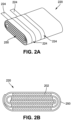
- FIGS. 2A-2B illustrate an embodiment of a vaporizer cartridge 220 including an embodiment of a heating element 250 including a flexible sheet with narrow electrically conductive traces 252 extending therealong. These narrow electrically conductive traces 252 form resistive heaters, which can be arranged in series or parallel.
- the narrow electrically conductive traces 252 can be made out of an electrically conductive material, such as any of the electrically conductive materials described herein.
- the heating element 250 can include at least one cartridge contact 224 that is in electrical communication with the narrow electrically conductive traces.
- the cartridge contacts 224 can be positioned such that when the vaporizer cartridge 220 is coupled to a vaporizer body, the cartridge contacts 224 can mate with the receptacle contacts 125 (shown in FIG.
- the flexible sheet can wrap around non-liquid source substance 202, such as a plurality of sheets of tobacco, as shown in FIG. 2B .
- the heating element 250 can both define a chamber configured to contain the source substance 202, as well as be contained within the chamber. This can increase the contact between the source substance 202 and the heating element 150, thereby allowing the heating element 150 to efficiently heat up and vaporize the vaporizable material from the source substance 202.
- a thermal gradient across the source substance 202 can be minimal (e.g., less than or equal to the width of a tobacco sheet) in such a configuration. This can allow the heating element 150 to heat to a temperature within the desired temperature range while also efficiently vaporizing an acceptable fraction (ideally but not necessarily all or substantially all) of the vaporizable material contained within the source substance 202 in the chamber.
- FIGS. 2C and 2D illustrate embodiments of the narrow electrically conductive traces 252 of the heating element 150.
- the narrow electrically conductive traces 252 can include a plurality of series heaters in parallel, such as six series heaters positioned in parallel.
- each series heater can be laid out in a horizontal orientation and/or in a vertical orientation, as shown in FIG. 2D .
- the horizontal orientation can provide a series resistance of approximately 2.18Ohm at 25°C and 4.09Ohm at 250°C and total heater resistance of approximately 0.363Ohm at 25°C and 0.682Ohm at 250°C.
- FIG. 2C illustrates the heating element 150 of FIG. 2A with the narrow electrically conductive traces 252 forming six series heaters in parallel, and with each series heater portion in a horizontal orientation
- FIGS. 3A-3B illustrates another embodiment of a vaporizer cartridge 320 including another embodiment of a heating element 350 (shown in FIG. 3B ) that allows the vaporizer cartridge 320 to include at least some of the benefits described herein, including cost effective manufacturing, fast heat-up time, vaporization temperatures within the desired temperature range, etc.
- the heating element 350 includes an electrically resistive area 354 made out of an electrically conductive material, such as an electrically conductive foil material treated to increase its electrical resistance in a desired part of the electrically conductive foil (e.g., by perforating, varying a thickness or other dimension of a conducive cross-section, etc.).
- a first part of the electrically resistive area 354 can include a non-conductive material backing 356 (e.g., paper material) and a second part of the electrically resistive area 354 can include the electrically resistive material 358 without the non-conductive material backing 356.
- the second part can include a plurality of perforations 360, which can create an electrical resistance along an otherwise more electrically conductive material of the second part.
- the perforations 360 can have any number of a variety of shapes and sizes and be arranged in one or more of a variety of configurations.
- the electrically resistive second part can be an electrically conductive material that includes more than one area having different densities of perforations 360 or other physical modifications, thereby creating different areas of electrical resistance. Such different areas of electrical resistance can affect the temperature reached when the electrically resistive part is caused to be heated (e.g., an electrical current is allowed to travel along). As shown in FIG.
- a part of the heating element 350 can include only a non-electrically conductive material, such as a part of the heating element 350 that may allow contact with a user and therefore may benefit from not becoming heated.
- Other configurations are also within the scope of this disclosure, such as heating elements having one or more areas including electrically conductive material without perforations, such as for forming a cartridge contact that may mate with a vaporizer contact for allowing current to be transferred from the vaporizer device to the heating element for heating the heating element.
- the heating element 350 can be wrapped around a source substance 302, such as a non-liquid source substance (e.g., one or more sheets of tobacco).
- a source substance 302 such as a non-liquid source substance (e.g., one or more sheets of tobacco).
- the heating element 350 can both define a chamber configured to contain the source substance 302, as well as be contained within the cartridge chamber. This can increase the contact between the source substance 302 and the heating element 350, thereby allowing the heating element 350 to efficiently heat up and vaporize vaporizable material from the source substance 302.
- a thermal gradient across the source substance 302 can be reduced (e.g., less than or equal to the width of a tobacco sheet) in such a configuration. This can allow the heating element 350 to heat to a temperature within the desired temperature range while also efficiently vaporizing an acceptable fraction (ideally but not necessarily all or substantially all) of the vaporizable material contained within the source material in the chamber.
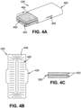
- FIGS. 4A-4E illustrate another embodiment of a vaporizer cartridge 420 including another embodiment of a heating element 450 (shown, for example, in FIG. 4B ) that allows the vaporizer cartridge 420 to include at least some of the benefits described herein, including cost effective manufacturing, fast heat-up time, vaporization temperatures within the desired temperature range, etc.
- the vaporizer cartridge 420 can include a housing 462 having an opening 464 for receiving the heating element 450 and source substance 402.
- the housing 462 can include a non-electrically conductive material and the heating element 450 can include a sheet 448 made out of thermally conductive material.
- the sheet 448 can include a plurality of perforations 460 that can affect the resistance along the sheet 448.
- the sheet can include at least one side extension forming cartridge contacts 424 that can mate with and extend through a through hole 428 along the housing 462.
- Such a side extension forming cartridge contacts 424 can be positioned to mate with a receptacle contact along a corresponding vaporizer body thereby allowing current to flow from the vaporizer body to the heating element 450 in turn allowing the heating element 450 to heat to a temperature within the desired temperature range.
- the heating element 450 may include at least one flat surface in which the source substance 402 can mate directly against, thereby providing efficient heat transfer between the heating element 450 and the source substance 402 (e.g., one or more sheets of tobacco). Furthermore, a thermal gradient across the source substance 402 can be minimal (e.g., less than or equal to the width of a tobacco sheet) in such a configuration. This can allow the heating element 450 to heat to a temperature within the desired temperature range while also efficiently vaporizing all or substantially all of the vaporizable material contained within the source substance 402 within the chamber.
- heating element 450 can be included, such as folding the heating element 450 in half with cartridge contacts 424 extending from a distal end (as shown in FIG. 4E ), and/or include an etched electrically conductive sheet 406 that is effectively long and thin for resulting in electrical resistance sufficient to achieve fast and effective heating of the heating element 450 to within the desired heating range (as shown, for example, in FIG. 4D ).
- one or more extensions 468 can extend from a top and/or bottom surface of the thermally conductive sheet 448. Such extensions 468 can be formed when forming the perforations 460 (e.g., via stamping the conductive sheet). The extensions 468 can provide additional surface area that may be more integrated with the source substance 402, such as compared to a flat heating element that does not include such extensions.
- some embodiments of the housing 462 can include a clamshell configuration such that the heating element 450 (e.g., any of the heating element embodiments shown in FIGS. 4A-4G ) can be captured in the housing 462 along with at least two tobacco sheets positioned on opposing sides of the heating element 450. This can provide a compact configuration with efficient assembly.
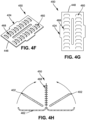
- FIGS. 5A-5B illustrates another embodiment of a vaporizer cartridge 520 including another embodiment of a heating element 550 having an induction coil and ferrous material 570.
- the induction coil can be wrapped around the source substance, such as directly around a sheet of source substance.
- the ferrous material 570 may be mixed with the source substance and may be heated as a result of interaction of the ferrous material with electrical and/or magnetic fields created by current passing through the inductive coil.
- the ferrous material inter-mixed with the source substance can allow a more even distribution of heat along and/or within the source substance, thereby reducing a thermal gradient along the source substance. This can allow heating of the source substance under interaction of the fields generated by the induction coil to a temperature within the desired temperature range and thereby effectively vaporize vaporizable material from the source substance.
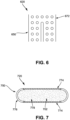
- FIG. 6 illustrates a side cross-section view of another embodiment of a vaporizer cartridge 620 including another embodiment of a heating element 650 having a thermally conductive (but electrically resistive) foam structure 672.
- the source substance may be placed into the conductive foam structure 672 (e.g., within pores of an open-cell thermally conductive foam structure). Current can be run through the thermally conductive foam structure 672 to thereby evenly heat the source substance as a result of resistive heating of the thermally conductive foam structure 672, such as at a temperature within the desired temperature range.
- the thermally conductive foam structure 672 can be made out of a reticulated carbon foam, an aluminum foam, etc. Other foam structures are within the scope of this disclosure.
- FIG. 7 illustrates another embodiment of a vaporizer cartridge 720 including another embodiment of a heating element 750 having conductive plates 774 separated by a non-conductive insulating material 776.
- the conductive plates 774 and insulating material 776 can define a chamber configured to contain source substance 702.
- the heating element 750 can further include an at least partially electrically conductive mixture 778 that can be included in the source substance 702, thereby creating a bulk resistor out of the source substance 702.
- the conductive plates 774 may function to conduct electricity and act as cartridge contacts that mate with receptacle contacts of the vaporizer body to which the vaporizer cartridge 720 is coupled.
- any of the heating elements described herein can include a contact (e.g., a cartridge contact) or can be in electrical communication with a contact for allowing electrical energy to be transmitted from a vaporizer body to which the vaporizer cartridge is coupled thereto and thereby allow the heating element to increase in temperature.
- a contact e.g., a cartridge contact
- a contact for allowing electrical energy to be transmitted from a vaporizer body to which the vaporizer cartridge is coupled thereto and thereby allow the heating element to increase in temperature.
- a reverse flow heat exchanger may be implemented into a vaporizer cartridge or vaporizer device.
- a vaporizer cartridge including a reverse flow heat exchanger is described in greater detail below.
- FIGS. 8A-8B illustrate another embodiment of a vaporizer cartridge 820 including another embodiment of a heating element 850.
- a thermally conductive material can encircle an outer circumference of an outer source substance passageway 880.
- the outer source substance passageway 880 can include a doughnut-shaped profile where the inner through-hole defines an inner source substance passageway 882.
- the inner source substance passageway 882 may be open at a distal end 884 and the outer source substance passageway 880 may include an opening at a distal end 884.
- the inner and outer source substance passageways may be at least partly filled with source substance.
- An airflow pathway 886 can extend between the opening to the outer source substance passageway 880, along at least a part of the source substance passageway, through a proximal end 888 of the inner source substance passageway 882, along the inner source substance passageway 882 and out the distal opening of the source substance passageway, as shown in FIG. 8B .
- This can allow airflow (e.g., as a result of a user inhaling on the vaporizer device) to flow along the outer source substance passageway 880, thereby becoming heated by thermally conductive material encircling the outer circumference of the source substance passageway.
- the heated airflow can increase the temperature of the source substance positioned along the inner source substance passageway 882. This can assist with increasing the speed at which the source substance contained in the inner source substance passageway heats to the desired temperature (e.g., within the desired temperature range) and reducing the temperature gradient throughout the source substance.
- At least some of the advantages of this concept may include a reduction in peak temperatures along the source substance that are greater than the desired temperature range. As such, this may result in at least a reduction in unwanted bi-products being created while vaporizing vaporizable material from the source substance. Additionally, since there is no direct contact between the source substance and the vaporizer device, minimal maintenance (e.g., cleaning, etc.) of the vaporizer device may be required.
- heating element and airflow passageway is described herein as being included in a vaporizer cartridge, any one or more parts of the heating element and airflow passageway described herein can be included in the vaporizer device, thereby configured to be reusable and durable.
- references to a structure or feature that is disposed "adjacent" another feature may have portions that overlap or underlie the adjacent feature.
- phrases such as "at least one of” or “one or more of” may occur followed by a conjunctive list of elements or features.
- the term “and/or” may also occur in a list of two or more elements or features. Unless otherwise implicitly or explicitly contradicted by the context in which it used, such a phrase is intended to mean any of the listed elements or features individually or any of the recited elements or features in combination with any of the other recited elements or features.
- the phrases “at least one of A and B;” “one or more of A and B;” and “A and/or B” are each intended to mean "A alone, B alone, or A and B together.”
- a similar interpretation is also intended for lists including three or more items.
- phrases “at least one of A, B, and C;” “one or more of A, B, and C;” and “A, B, and/or C” are each intended to mean “A alone, B alone, C alone, A and B together, A and C together, B and C together, or A and B and C together.”
- Use of the term “based on,” above and in the claims is intended to mean, “based at least in part on,” such that an unrecited feature or element is also permissible.
- spatially relative terms such as “forward”, “rearward”, “under”, “below”, “lower”, “over”, “upper” and the like, may be used herein for ease of description to describe one element or feature's relationship to another element(s) or feature(s) as illustrated in the figures. It will be understood that the spatially relative terms are intended to encompass different orientations of the device in use or operation in addition to the orientation depicted in the figures. For example, if a device in the figures is inverted, elements described as “under” or “beneath” other elements or features would then be oriented “over” the other elements or features. Thus, the exemplary term “under” can encompass both an orientation of over and under.
- the device may be otherwise oriented (rotated 90 degrees or at other orientations) and the spatially relative descriptors used herein interpreted accordingly.
- the terms “upwardly”, “downwardly”, “vertical”, “horizontal” and the like are used herein for the purpose of explanation only unless specifically indicated otherwise.
- first and second may be used herein to describe various features/elements (including steps), these features/elements should not be limited by these terms, unless the context indicates otherwise. These terms may be used to distinguish one feature/element from another feature/element. Thus, a first feature/element discussed below could be termed a second feature/element, and similarly, a second feature/element discussed below could be termed a first feature/element without departing from the teachings provided herein.
- a numeric value may have a value that is +/- 0.1% of the stated value (or range of values), +/- 1% of the stated value (or range of values), +/- 2% of the stated value (or range of values), +/- 5% of the stated value (or range of values), +/- 10% of the stated value (or range of values), etc.
- Any numerical values given herein should also be understood to include about or approximately that value, unless the context indicates otherwise. For example, if the value "10" is disclosed, then “about 10" is also disclosed. Any numerical range recited herein is intended to include all sub-ranges subsumed therein.
- One or more aspects or features of the subject matter described herein can be realized in digital electronic circuitry, integrated circuitry, specially designed application specific integrated circuits (ASICs), field programmable gate arrays (FPGAs) computer hardware, firmware, software, and/or combinations thereof.
- ASICs application specific integrated circuits
- FPGAs field programmable gate arrays
- These various aspects or features can include implementation in one or more computer programs that are executable and/or interpretable on a programmable system including at least one programmable processor, which can be special or general purpose, coupled to receive data and instructions from, and to transmit data and instructions to, a storage system, at least one input device, and at least one output device.
- the programmable system or computing system may include clients and servers.
- a client and server are generally remote from each other and typically interact through a communication network. The relationship of client and server arises by virtue of computer programs running on the respective computers and having a client-server relationship to each other.
- machine-readable signal refers to any signal used to provide machine instructions and/or data to a programmable processor.
- the machine-readable medium can store such machine instructions non-transitorily, such as for example as would a nontransient solid-state memory or a magnetic hard drive or any equivalent storage medium.
- the machine-readable medium can alternatively or additionally store such machine instructions in a transient manner, such as for example, as would a processor cache or other random access memory associated with one or more physical processor cores.
Landscapes
- Health & Medical Sciences (AREA)
- Engineering & Computer Science (AREA)
- Life Sciences & Earth Sciences (AREA)
- Animal Behavior & Ethology (AREA)
- Anesthesiology (AREA)
- Biomedical Technology (AREA)
- Heart & Thoracic Surgery (AREA)
- Hematology (AREA)
- Veterinary Medicine (AREA)
- Public Health (AREA)
- General Health & Medical Sciences (AREA)
- Pulmonology (AREA)
- Bioinformatics & Cheminformatics (AREA)
- Chemical & Material Sciences (AREA)
- Chemical Kinetics & Catalysis (AREA)
- General Chemical & Material Sciences (AREA)
- Emergency Medicine (AREA)
- Catching Or Destruction (AREA)
Claims (11)
- Kartusche (820) für eine Verdampfervorrichtung, wobei die Kartusche (820) zum Fassen eines nicht flüssigen verdampfbaren Materials eingerichtet ist, wobei die Kartusche (820) umfasst:einen äußeren Quellsubstanzdurchgang (880);eine erste Öffnung an einem distalen Ende der Kartusche (820), wobei die erste Öffnung in Fluidverbindung mit dem äußeren Quellsubstanzdurchgang (880) steht;einen inneren Quellsubstanzdurchgang (882); undeine zweite Öffnung an dem distalen Ende der Kartusche (820), wobei die zweite Öffnung in Fluidverbindung mit dem inneren Quellsubstanzdurchgang (882) steht, wobei der äußere Quellsubstanzdurchgang (880) und der innere Quellsubstanzdurchgang (882) einen Luftstromweg definieren, der sich zwischen der ersten Öffnung und der zweiten Öffnung erstreckt.
- Kartusche (820) nach Anspruch 1, wobei der äußere Quellsubstanzdurchgang (880) den inneren Quellsubstanzdurchgang (882) umgibt.
- Kartusche (820) nach einem der vorangehenden Ansprüche, wobei der äußere Quellsubstanzdurchgang (880) und der innere Quellsubstanzdurchgang (882) ein ringförmiges Profil bilden, wobei der innere Quellsubstanzdurchgang (882) eine innere Durchgangsbohrung des ringförmigen Profils definiert.
- Kartusche (820) nach einem der vorangehenden Ansprüche, wobei die Kartusche (820) derart eingerichtet ist, dass sie in der Nähe eines Heizelements einer Verdampfervorrichtung angeordnet ist und von diesem erwärmt wird.
- Kartusche (820) nach Anspruch 4, wobei ein wärmeleitendes Material einen Außenumfang des äußeren Quellsubstanzdurchgangs (880) bildet.
- Kartusche (820) nach Anspruch 5, wobei das wärmeleitende Material dazu eingerichtet ist, Wärme von dem Heizelement zu leiten, um Luft zu erwärmen, die durch den äußeren Quellsubstanzdurchgang (880) strömt, um einen erwärmten Luftstrom zu erzeugen, wobei der erwärmte Luftstrom anschließend durch den inneren Quellsubstanzdurchgang (882) strömt und das in dem inneren Quellsubstanzdurchgang (882) angeordnete nicht flüssige verdampfbare Material erwärmt, um ein Aerosol zu erzeugen, wobei das Aerosol von einem Benutzer über die zweite Öffnung inhaliert wird.
- Kartusche (820) nach einem der vorangehenden Ansprüche, wobei das nicht flüssige verdampfbare Material in dem äußeren Quellsubstanzdurchgang (880) angeordnet ist.
- Kartusche (820) nach einem der vorangehenden Ansprüche, wobei das nicht flüssige verdampfbare Material in dem inneren Quellsubstanzdurchgang (882) angeordnet ist.
- Verdampfer, umfassend:
eine Heizkammer, die zur Aufnahme einer Kartusche (820) nach einem der vorangehenden Ansprüche eingerichtet ist. - Verdampfer, umfassend:eine Heizkammer; undeine in der Heizkammer angeordnete Kartusche (820) nach einem der vorangehenden Ansprüche.
- Verfahren zur Nutzung einer Kartusche (820) nach einem der Ansprüche 1-8, das umfasst:Einsetzen der Kartusche (820) in eine Heizkammer eines Verdampfers; undInhalieren an einem Mundstück des Verdampfers, um zu bewirken, dass Luft entlang des Luftstromweges strömt, während die Kartusche (820) von der Heizkammer erwärmt wird.
Priority Applications (2)
| Application Number | Priority Date | Filing Date | Title |
|---|---|---|---|
| EP25223476.0A EP4694574A2 (de) | 2018-07-31 | 2019-07-31 | Kartuschenbasierter verdampfer mit nicht brennender wärme |
| EP24189958.2A EP4427778B1 (de) | 2018-07-31 | 2019-07-31 | Kartuschenbasierter verdampfer mit nicht brennender wärme |
Applications Claiming Priority (2)
| Application Number | Priority Date | Filing Date | Title |
|---|---|---|---|
| US201862712919P | 2018-07-31 | 2018-07-31 | |
| PCT/US2019/044546 WO2020028591A1 (en) | 2018-07-31 | 2019-07-31 | Cartridge-based heat not burn vaporizer |
Related Child Applications (2)
| Application Number | Title | Priority Date | Filing Date |
|---|---|---|---|
| EP25223476.0A Division EP4694574A2 (de) | 2018-07-31 | 2019-07-31 | Kartuschenbasierter verdampfer mit nicht brennender wärme |
| EP24189958.2A Division EP4427778B1 (de) | 2018-07-31 | 2019-07-31 | Kartuschenbasierter verdampfer mit nicht brennender wärme |
Publications (3)
| Publication Number | Publication Date |
|---|---|
| EP3829366A1 EP3829366A1 (de) | 2021-06-09 |
| EP3829366C0 EP3829366C0 (de) | 2024-07-24 |
| EP3829366B1 true EP3829366B1 (de) | 2024-07-24 |
Family
ID=67659980
Family Applications (3)
| Application Number | Title | Priority Date | Filing Date |
|---|---|---|---|
| EP19753543.8A Active EP3829366B1 (de) | 2018-07-31 | 2019-07-31 | Cartridge-basierte hitze nicht brennen verdampfer |
| EP25223476.0A Pending EP4694574A2 (de) | 2018-07-31 | 2019-07-31 | Kartuschenbasierter verdampfer mit nicht brennender wärme |
| EP24189958.2A Active EP4427778B1 (de) | 2018-07-31 | 2019-07-31 | Kartuschenbasierter verdampfer mit nicht brennender wärme |
Family Applications After (2)
| Application Number | Title | Priority Date | Filing Date |
|---|---|---|---|
| EP25223476.0A Pending EP4694574A2 (de) | 2018-07-31 | 2019-07-31 | Kartuschenbasierter verdampfer mit nicht brennender wärme |
| EP24189958.2A Active EP4427778B1 (de) | 2018-07-31 | 2019-07-31 | Kartuschenbasierter verdampfer mit nicht brennender wärme |
Country Status (8)
| Country | Link |
|---|---|
| US (4) | US11464082B2 (de) |
| EP (3) | EP3829366B1 (de) |
| JP (2) | JP7577644B2 (de) |
| KR (2) | KR102878359B1 (de) |
| CN (2) | CN113194766B (de) |
| CA (1) | CA3107937A1 (de) |
| MX (2) | MX2021001167A (de) |
| WO (1) | WO2020028591A1 (de) |
Families Citing this family (33)
| Publication number | Priority date | Publication date | Assignee | Title |
|---|---|---|---|---|
| US12201767B2 (en) | 2016-04-22 | 2025-01-21 | Juul Labs, Inc. | Aerosol devices having compartmentalized materials |
| US20210212364A1 (en) * | 2018-07-26 | 2021-07-15 | Philip Morris Products S.A. | Article for forming an aerosol |
| EP3829366B1 (de) | 2018-07-31 | 2024-07-24 | Juul Labs, Inc. | Cartridge-basierte hitze nicht brennen verdampfer |
| US11413409B2 (en) | 2018-09-12 | 2022-08-16 | Juul Labs, Inc. | Vaporizer including positive temperature coefficient of resistivity (PTCR) heating element |
| KR102768271B1 (ko) | 2018-11-05 | 2025-02-13 | 쥴 랩스, 인크. | 기화기 디바이스용 카트리지 |
| EP4393336A3 (de) | 2018-11-08 | 2024-10-09 | Juul Labs, Inc. | Verdampfervorrichtung mit mehr als einem heizelement |
| WO2020154690A1 (en) | 2019-01-25 | 2020-07-30 | Juul Labs, Inc. | Vaporizer device and cartridge |
| EP4585242A3 (de) | 2019-06-12 | 2025-08-20 | Juul Labs, Inc. | Aufdampfbarer materialeinsatz für verdampfervorrichtung |
| JP7614175B2 (ja) | 2019-08-08 | 2025-01-15 | ジュール・ラブズ・インコーポレイテッド | 気化器デバイス用の気化可能材料インサート |
| EP4674296A2 (de) | 2019-09-06 | 2026-01-07 | Juul Labs, Inc. | Kartuschenbasierter verdampfer mit nicht brennender wärme |
| US11607511B2 (en) * | 2020-01-08 | 2023-03-21 | Nicoventures Trading Limited | Inductively-heated substrate tablet for aerosol delivery device |
| EP4146026A1 (de) * | 2020-05-07 | 2023-03-15 | Juul Labs, Inc. | Verdampferkartusche zum erwärmen von mehr als einem verdampfbaren material |
| US11812785B2 (en) * | 2020-06-23 | 2023-11-14 | Altria Client Services Llc | Capsules including internal heaters, heat-not-burn (HNB) aerosol-generating devices, and methods of generating an aerosol |
| WO2022024310A1 (ja) * | 2020-07-30 | 2022-02-03 | 日本たばこ産業株式会社 | 香味吸引器用のカートリッジ及び香味吸引器 |
| WO2022024311A1 (ja) * | 2020-07-30 | 2022-02-03 | 日本たばこ産業株式会社 | 香味吸引器用のカートリッジ及び香味吸引器 |
| US20240057667A1 (en) * | 2021-01-08 | 2024-02-22 | Nicoventures Trading Limited | An assembly for an aerosol provision device |
| US12274295B2 (en) | 2021-01-18 | 2025-04-15 | Altria Client Services Llc | Heat-not-burn (HNB) aerosol-generating devices and capsules |
| US12011034B2 (en) * | 2021-01-18 | 2024-06-18 | Altria Client Services Llc | Capsules including embedded heaters and heat-not-burn (HNB) aerosol-generating devices |
| US11910826B2 (en) * | 2021-01-18 | 2024-02-27 | Altria Client Services Llc | Heat-not-burn (HNB) aerosol-generating devices and capsules |
| USD1095794S1 (en) | 2021-01-18 | 2025-09-30 | Altria Client Services Llc | Aerosol-generating capsule |
| US12114695B2 (en) | 2021-02-12 | 2024-10-15 | Predictably Human, Inc. | Addiction cessation systems, devices, and methods |
| CN215347057U (zh) * | 2021-03-29 | 2021-12-31 | 深圳市合元科技有限公司 | 气雾生成装置及用于气雾生成装置的电阻加热器 |
| CA3225939A1 (en) * | 2021-07-16 | 2023-01-19 | Robert Francis Jacobs Jr. | Drug delivery systems, devices, and methods |
| US12127592B2 (en) | 2021-09-20 | 2024-10-29 | Altria Client Services Llc | Capsule validation for heat-not-burn (HNB) aerosol-generating devices |
| US12063980B2 (en) * | 2021-11-01 | 2024-08-20 | Patrick Tidalgo | System and apparatus for intelligent vaporizer |
| WO2024104948A1 (en) * | 2022-11-14 | 2024-05-23 | Jt International Sa | Tobacco article comprising a resistive layer and associated aerosol generating assembly |
| EP4648628A1 (de) * | 2023-01-12 | 2025-11-19 | N2B Limited | Beschichtung für rauchkapsel |
| EP4648638A1 (de) | 2023-01-12 | 2025-11-19 | N2B Limited | Rauchvorrichtung mit flachlegefunktion |
| WO2025031958A1 (en) * | 2023-08-10 | 2025-02-13 | Philip Morris Products S.A. | Cartridge for use in an aerosol-generating device |
| GB202313859D0 (en) * | 2023-09-12 | 2023-10-25 | Nicoventures Trading Ltd | Aerosol generator |
| WO2025056627A1 (en) * | 2023-09-12 | 2025-03-20 | Nicoventures Trading Limited | Aerosol provision system |
| EP4646947A1 (de) * | 2024-05-07 | 2025-11-12 | Nicoventures Trading Limited | Aerosolerzeuger |
| EP4646948A1 (de) * | 2024-05-07 | 2025-11-12 | Nicoventures Trading Limited | Aerosolerzeuger |
Citations (3)
| Publication number | Priority date | Publication date | Assignee | Title |
|---|---|---|---|---|
| US20170164657A1 (en) * | 2014-07-11 | 2017-06-15 | Philip Morris Products S.A. | Aerosol-forming cartridge comprising a tobacco-containing material |
| WO2017129617A1 (en) * | 2016-01-25 | 2017-08-03 | Philip Morris Products S.A. | Cartridge assembly comprising a guide slot |
| WO2017207582A1 (en) * | 2016-05-31 | 2017-12-07 | Philip Morris Products S.A. | Refillable aerosol-generating article |
Family Cites Families (321)
| Publication number | Priority date | Publication date | Assignee | Title |
|---|---|---|---|---|
| US3373915A (en) | 1965-06-28 | 1968-03-19 | Riegel Paper Corp | Moldable pouch material |
| US3559655A (en) | 1969-02-25 | 1971-02-02 | Sutton Res Corp | Oxidized cellulose substitute smoking material and method of making same |
| US3584631A (en) | 1969-08-25 | 1971-06-15 | Amf Inc | Reconstituted tobacco composition |
| GB1484573A (en) | 1974-07-16 | 1977-09-01 | Ici Ltd | Smoking mixtures |
| US5042509A (en) | 1984-09-14 | 1991-08-27 | R. J. Reynolds Tobacco Company | Method for making aerosol generating cartridge |
| US4708151A (en) | 1986-03-14 | 1987-11-24 | R. J. Reynolds Tobacco Company | Pipe with replaceable cartridge |
| US4819665A (en) | 1987-01-23 | 1989-04-11 | R. J. Reynolds Tobacco Company | Aerosol delivery article |
| US5065776A (en) | 1990-08-29 | 1991-11-19 | R. J. Reynolds Tobacco Company | Cigarette with tobacco/glass fuel wrapper |
| US5249586A (en) | 1991-03-11 | 1993-10-05 | Philip Morris Incorporated | Electrical smoking |
| US5479948A (en) | 1993-08-10 | 1996-01-02 | Philip Morris Incorporated | Electrical smoking article having continuous tobacco flavor web and flavor cassette therefor |
| US5944025A (en) * | 1996-12-30 | 1999-08-31 | Brown & Williamson Tobacco Company | Smokeless method and article utilizing catalytic heat source for controlling products of combustion |
| US6769436B2 (en) | 2002-06-28 | 2004-08-03 | Richard C. Horian | Volatile inhaler and method |
| JPWO2004089126A1 (ja) | 2003-04-01 | 2006-07-06 | 修成 高野 | ニコチン吸引パイプ及びニコチンホルダ |
| WO2005032285A1 (en) | 2003-09-30 | 2005-04-14 | R. J. Reynolds Tobacco Company | Smokable rod for a cigarette |
| US7997280B2 (en) | 2004-01-30 | 2011-08-16 | Joshua Rosenthal | Portable vaporizer |
| US7540286B2 (en) * | 2004-06-03 | 2009-06-02 | Alexza Pharmaceuticals, Inc. | Multiple dose condensation aerosol devices and methods of forming condensation aerosols |
| WO2006022714A1 (en) | 2004-08-12 | 2006-03-02 | Alexza Pharmaceuticals, Inc. | Aerosol drug delivery device incorporating percussively activated heat packages |
| US7438072B2 (en) | 2005-03-02 | 2008-10-21 | Izuchukwu John I | Portable field anesthesia machine and control therefore |
| KR101301325B1 (ko) | 2005-04-29 | 2013-08-29 | 필립모리스 프로덕츠 에스.에이. | 담배 쌈지 제품 |
| US9675109B2 (en) | 2005-07-19 | 2017-06-13 | J. T. International Sa | Method and system for vaporization of a substance |
| US20160345631A1 (en) | 2005-07-19 | 2016-12-01 | James Monsees | Portable devices for generating an inhalable vapor |
| US7918231B2 (en) | 2006-01-31 | 2011-04-05 | U.S. Smokeless Tobacco Company Llc | Tobacco articles and methods |
| US20070221234A1 (en) | 2006-03-27 | 2007-09-27 | Beckstead Kenneth M | Butt refuse receptacle |
| WO2008029381A2 (en) | 2006-09-05 | 2008-03-13 | Oglesby & Butler Research & Development Limited | A container comprising vaporisable matter for use in a vaporising device for vaporising a vaporisable constituent thereof |
| US7726320B2 (en) | 2006-10-18 | 2010-06-01 | R. J. Reynolds Tobacco Company | Tobacco-containing smoking article |
| US8015979B2 (en) | 2007-02-08 | 2011-09-13 | Cooper Jack B | Cigar |
| US8991402B2 (en) | 2007-12-18 | 2015-03-31 | Pax Labs, Inc. | Aerosol devices and methods for inhaling a substance and uses thereof |
| AT507187B1 (de) | 2008-10-23 | 2010-03-15 | Helmut Dr Buchberger | Inhalator |
| JP4739433B2 (ja) | 2009-02-07 | 2011-08-03 | 和彦 清水 | 無煙喫煙治具 |
| JP5388241B2 (ja) | 2009-02-23 | 2014-01-15 | 日本たばこ産業株式会社 | 非加熱型香味吸引器 |
| US8897628B2 (en) | 2009-07-27 | 2014-11-25 | Gregory D. Conley | Electronic vaporizer |
| US8813747B2 (en) | 2009-08-07 | 2014-08-26 | Hexbg, Llc | Vaporizer system for delivery of inhalable substances |
| US8464726B2 (en) | 2009-08-24 | 2013-06-18 | R.J. Reynolds Tobacco Company | Segmented smoking article with insulation mat |
| US8490629B1 (en) | 2009-08-31 | 2013-07-23 | Incredibowl Industries, Llc | Therapeutic smoking device |
| EP2340729A1 (de) | 2009-12-30 | 2011-07-06 | Philip Morris Products S.A. | Verbessertes Heizgerät für ein elektrisch beheiztes Aerosolerzeugungssystem |
| US8869792B1 (en) | 2010-07-22 | 2014-10-28 | Chung Ju Lee | Portable vaporizer |
| KR101057774B1 (ko) | 2010-12-13 | 2011-08-19 | 신종수 | 전자담배 |
| CN102326869B (zh) | 2011-05-12 | 2013-04-03 | 陈志平 | 电子雾化吸入器的雾化嘴 |
| KR20120008751U (ko) * | 2011-06-13 | 2012-12-24 | 이영찬 | 전자담배 |
| US9078473B2 (en) | 2011-08-09 | 2015-07-14 | R.J. Reynolds Tobacco Company | Smoking articles and use thereof for yielding inhalation materials |
| KR20240001273A (ko) | 2011-08-16 | 2024-01-03 | 쥴 랩스, 인크. | 저온 전자 증발 장치 및 방법 |
| HK1198105A1 (en) | 2011-10-25 | 2015-03-13 | Philip Morris Products S.A. | Aerosol generating device with heater assembly |
| EP2589306A1 (de) | 2011-11-01 | 2013-05-08 | Philip Morris Products S.A. | Vorrichtung zur Behandlung eines Rauchartikels |
| UA112883C2 (uk) | 2011-12-08 | 2016-11-10 | Філіп Морріс Продактс С.А. | Пристрій для утворення аерозолю з капілярним примежовим шаром |
| EP2800486B1 (de) | 2012-01-03 | 2016-08-31 | Philip Morris Products S.a.s. | Aerosolerzeugungsvorrichtung und -system mit verbessertem luftstrom |
| US9078474B2 (en) | 2012-01-30 | 2015-07-14 | Spencer Thompson | Cartomizer for electronic cigarettes |
| US9326547B2 (en) | 2012-01-31 | 2016-05-03 | Altria Client Services Llc | Electronic vaping article |
| TW201340892A (zh) * | 2012-02-13 | 2013-10-16 | Philip Morris Prod | 包括隔離可燃熱源之吸煙製品 |
| MX2014010189A (es) | 2012-02-22 | 2014-11-14 | Altria Client Services Inc | Articulo electronico para fumar y elemento calentador mejorado. |
| WO2013138384A2 (en) | 2012-03-12 | 2013-09-19 | Uptoke Llc | Electronic vaporizing device and methods for use |
| US20130255702A1 (en) | 2012-03-28 | 2013-10-03 | R.J. Reynolds Tobacco Company | Smoking article incorporating a conductive substrate |
| AU2013352004B2 (en) | 2012-11-28 | 2019-02-14 | Fontem Holdings 1 B.V. | Methods and devices for compound delivery |
| US10034988B2 (en) | 2012-11-28 | 2018-07-31 | Fontem Holdings I B.V. | Methods and devices for compound delivery |
| US9271529B2 (en) | 2013-02-05 | 2016-03-01 | Atmos Nation Llc | Portable vaporization apparatus |
| CN105188426B (zh) | 2013-02-22 | 2018-01-16 | 奥驰亚客户服务有限责任公司 | 电子吸烟器具 |
| US9993023B2 (en) | 2013-02-22 | 2018-06-12 | Altria Client Services Llc | Electronic smoking article |
| CN105208882B (zh) | 2013-02-22 | 2019-07-23 | 奥驰亚客户服务有限责任公司 | 电子吸烟器具 |
| US9723876B2 (en) | 2013-03-15 | 2017-08-08 | Altria Client Services Llc | Electronic smoking article |
| US10653180B2 (en) | 2013-06-14 | 2020-05-19 | Juul Labs, Inc. | Multiple heating elements with separate vaporizable materials in an electric vaporization device |
| US10098381B2 (en) | 2013-03-15 | 2018-10-16 | Altria Client Services Llc | Electronic smoking article |
| US10264819B2 (en) | 2013-03-15 | 2019-04-23 | Altria Client Services Llc | Electronic smoking article |
| PL2810570T3 (pl) | 2013-06-03 | 2019-06-28 | Fontem Holdings 1 B.V. | System z elektronicznym urządzeniem do palenia i kapsułką |
| CN203378557U (zh) | 2013-06-19 | 2014-01-08 | 刘秋明 | 一种电子烟 |
| EA033402B1 (ru) | 2013-07-19 | 2019-10-31 | Altria Client Services Llc | Жидкая аэрозольная композиция для электронного курительного изделия |
| US12290631B2 (en) | 2013-07-19 | 2025-05-06 | Altria Client Services Llc | Electronic smoking article |
| US10251422B2 (en) | 2013-07-22 | 2019-04-09 | Altria Client Services Llc | Electronic smoking article |
| US10390562B2 (en) | 2013-07-23 | 2019-08-27 | Altria Client Services Llc | Electronic smoking article |
| US9877511B2 (en) | 2013-07-24 | 2018-01-30 | Altria Client Services Llc | Electronic smoking article |
| WO2015013329A1 (en) | 2013-07-25 | 2015-01-29 | Altria Client Services Inc. | Electronic smoking article |
| US20150027468A1 (en) | 2013-07-25 | 2015-01-29 | Altria Client Services Inc. | Electronic smoking article |
| US10694782B2 (en) | 2013-07-30 | 2020-06-30 | Altria Client Services Llc | Electronic vaping device and vapor generating apparatus |
| CN203482896U (zh) | 2013-08-02 | 2014-03-19 | 刘秋明 | 电子烟 |
| CN203467677U (zh) | 2013-09-25 | 2014-03-12 | 卓尔悦(常州)电子科技有限公司 | 电子烟透明雾化器 |
| WO2015048388A1 (en) | 2013-09-26 | 2015-04-02 | Altria Client Services Inc. | Electronic smoking article |
| EA032410B1 (ru) | 2013-09-27 | 2019-05-31 | Олтриа Клайент Сервисиз Ллк | Электронное курительное изделие |
| CN103932401B (zh) | 2013-09-29 | 2015-09-30 | 深圳麦克韦尔股份有限公司 | 电子烟 |
| RU2629878C1 (ru) | 2013-09-30 | 2017-09-04 | Джапан Тобакко Инк. | Ароматический ингалятор негорящего типа |
| US10039321B2 (en) | 2013-11-12 | 2018-08-07 | Vmr Products Llc | Vaporizer |
| GB201320231D0 (en) | 2013-11-15 | 2014-01-01 | British American Tobacco Co | Aerosol generating material and devices including the same |
| UA118858C2 (uk) | 2013-12-05 | 2019-03-25 | Філіп Морріс Продактс С.А. | Виріб, що генерує аерозоль, з жорстким порожнистим наконечником |
| UA118457C2 (uk) | 2013-12-05 | 2019-01-25 | Філіп Морріс Продактс С.А. | Нагрівний виріб, що генерує аерозоль, з перегородкою для повітряного потоку |
| US10159282B2 (en) | 2013-12-23 | 2018-12-25 | Juul Labs, Inc. | Cartridge for use with a vaporizer device |
| CN103750570B (zh) | 2014-01-15 | 2016-02-24 | 林光榕 | 方便注液的电子烟及制造方法和注液方法 |
| PL3096636T3 (pl) | 2014-01-22 | 2020-11-16 | Fontem Holdings 1 B.V. | Sposoby i urządzenia do łagodzenia potrzeby palenia |
| CN103783674A (zh) * | 2014-01-24 | 2014-05-14 | 深圳市合元科技有限公司 | 烘焙式雾化装置及气雾吸入装置 |
| CN106163305A (zh) | 2014-01-27 | 2016-11-23 | Sis资源有限公司 | 电子蒸汽吐烟装置中的有线通信 |
| MY205339A (en) | 2014-02-28 | 2024-10-16 | Altria Client Services Llc | Electronic vaping device and components thereof |
| WO2015143666A1 (zh) | 2014-03-27 | 2015-10-01 | 深圳麦克韦尔股份有限公司 | 电子烟 |
| WO2015155289A1 (en) | 2014-04-10 | 2015-10-15 | Philip Morris Products S.A. | Aerosol-generating device with helix-shaped heater |
| WO2015186000A2 (en) | 2014-04-14 | 2015-12-10 | Altria Client Services Inc. | Method and system for the automated production of e-vapor devices |
| US20150313275A1 (en) | 2014-04-30 | 2015-11-05 | Altria Client Services, Inc. | Liquid aerosol formulation of an electronic smoking article |
| SG11201606430QA (en) | 2014-04-30 | 2016-09-29 | Philip Morris Products Sa | A container having a heater for an aerosol-generating device, and aerosol-generating device |
| CN203883521U (zh) | 2014-05-15 | 2014-10-15 | 林光榕 | 电子烟磁吸式充电装置 |
| US20150335070A1 (en) | 2014-05-20 | 2015-11-26 | R.J. Reynolds Tobacco Company | Electrically-powered aerosol delivery system |
| TWI661782B (zh) | 2014-05-21 | 2019-06-11 | Philip Morris Products S. A. | 電熱式氣溶膠產生系統、電熱式氣溶膠產生裝置及產生氣溶膠之方法 |
| TWI635897B (zh) * | 2014-05-21 | 2018-09-21 | 瑞士商菲利浦莫里斯製品股份有限公司 | 氣溶膠形成基材及氣溶膠傳遞系統 |
| TWI669072B (zh) | 2014-05-21 | 2019-08-21 | 瑞士商菲利浦莫里斯製品股份有限公司 | 電熱式霧劑產生系統及用於此系統中之匣筒 |
| CN204599330U (zh) | 2014-06-23 | 2015-09-02 | 惠州市吉瑞科技有限公司 | 一种电子烟 |
| GB2527597B (en) | 2014-06-27 | 2016-11-23 | Relco Induction Dev Ltd | Electronic Vapour Inhalers |
| CA2951354A1 (en) * | 2014-07-11 | 2016-01-14 | Philip Morris Products S.A. | Aerosol-generating system with improved air flow control |
| WO2016023182A1 (zh) | 2014-08-13 | 2016-02-18 | 惠州市吉瑞科技有限公司 | 一种雾化器以及电子烟 |
| GB2529201A (en) * | 2014-08-13 | 2016-02-17 | Batmark Ltd | Device and method |
| EP3760059B1 (de) | 2014-09-17 | 2022-10-26 | Fontem Holdings 4 B.V. | Vorrichtung zum speichern und verdampfen flüssiger medien |
| EP3760056B1 (de) | 2014-09-30 | 2023-08-30 | Philip Morris Products S.A. | Verfahren zur herstellung von homogenisiertem tabakmaterial |
| CN106714595A (zh) | 2014-10-03 | 2017-05-24 | 奥驰亚客户服务有限责任公司 | 电子烟装置及其组件 |
| EP3206515A4 (de) | 2014-10-15 | 2018-10-31 | Altria Client Services LLC | Elektronische dampfvorrichtung und komponenten davon |
| GB201418817D0 (en) | 2014-10-22 | 2014-12-03 | British American Tobacco Co | Apparatus and method for generating an inhalable medium, and a cartridge for use therewith |
| WO2016063776A1 (ja) | 2014-10-24 | 2016-04-28 | 日本たばこ産業株式会社 | 香味源の製造方法及びパッケージ |
| CN107072307B (zh) | 2014-10-28 | 2020-01-10 | 惠州市吉瑞科技有限公司 | 电子烟 |
| CN104366695B (zh) | 2014-10-29 | 2017-12-08 | 深圳麦克韦尔股份有限公司 | 雾化器、雾化组件及吸入器 |
| WO2016069884A2 (en) | 2014-10-29 | 2016-05-06 | Altria Client Services Llc | E-vaping section for an e-vaping device |
| CN106998811B (zh) | 2014-10-29 | 2021-05-07 | 奥驰亚客户服务有限责任公司 | 用于电子烟装置的无乙醇凝胶配方筒体 |
| CN107106797A (zh) | 2014-10-29 | 2017-08-29 | 奥驰亚客户服务有限责任公司 | 电子烟筒体 |
| EA201790981A1 (ru) | 2014-11-05 | 2017-08-31 | Олтриа Клайент Сервисиз Ллк | Электронное вейпинговое устройство |
| US10440991B2 (en) | 2014-11-05 | 2019-10-15 | Altria Client Services Llc | Reservoir filling system for an electronic vaping device |
| GB2568411B (en) | 2014-11-11 | 2019-08-07 | Jt Int Sa | Electronic vapour inhalers |
| GB2546934B (en) | 2014-11-11 | 2018-04-11 | Jt Int Sa | Electronic vapour inhalers |
| CN115530445A (zh) | 2014-11-19 | 2022-12-30 | 富特姆投资有限公司 | 用于使来自非可燃吸烟制品的气溶胶功能化的方法、组合物和装置 |
| JP6771465B2 (ja) | 2014-12-15 | 2020-10-21 | フィリップ・モーリス・プロダクツ・ソシエテ・アノニム | エアロゾルの特性を制御するためのエアロゾルの生成を制御する方法 |
| US9681688B1 (en) | 2014-12-16 | 2017-06-20 | Altria Client Services Llc | E-vaping device |
| US9648908B1 (en) | 2014-12-16 | 2017-05-16 | Altria Client Services Llc | E-vaping device |
| WO2016095234A1 (zh) | 2014-12-19 | 2016-06-23 | 深圳麦克韦尔股份有限公司 | 电子烟 |
| EP3042579A1 (de) | 2015-01-09 | 2016-07-13 | Fontem Holdings 1 B.V. | Elektronische Rauchvorrichtung |
| EP3047741B1 (de) | 2015-01-21 | 2018-05-16 | Fontem Holdings 1 B.V. | Elektronische Rauchvorrichtung |
| GB201501060D0 (en) | 2015-01-22 | 2015-03-11 | Nicoventures Holdings Ltd | Vapour provision system and cartridge therefor |
| EP3056099B1 (de) | 2015-02-16 | 2018-04-04 | Fontem Holdings 1 B.V. | Elektronische Rauchvorrichtung mit einschnappbarer Rastverbindung |
| EP3061358A1 (de) | 2015-02-26 | 2016-08-31 | Fontem Holdings 2 B.V. | Elektronische Rauchvorrichtung mit einem Luftvorwärmungselement |
| PL3066941T3 (pl) | 2015-03-13 | 2019-12-31 | Fontem Holdings 1 B.V. | Podzespół generujący aerozol do elektronicznego urządzenia do palenia, elektroniczne urządzenie do palenia i sposób generowania środka wziewnego |
| EP3069620B2 (de) | 2015-03-19 | 2021-02-24 | Fontem Holdings 1 B.V. | Elektronische rauchvorrichtung |
| DE202015009813U1 (de) | 2015-03-19 | 2020-04-02 | Fontem Holdings 1 B.V. | Elektronische Rauchvorrichtung |
| EP3272233A4 (de) | 2015-03-19 | 2018-11-21 | Japan Tobacco, Inc. | Verfahren zur herstellung eines tabakformartikels |
| KR101677547B1 (ko) | 2015-03-20 | 2016-11-18 | 주식회사 케이티앤지 | 향미 유지 무연화 가능 전자 담배 장치 |
| CN104770878B (zh) | 2015-03-23 | 2017-11-24 | 云南中烟工业有限责任公司 | 一种具有电子烟抽吸功能的电加热型卷烟抽吸装置 |
| EP3075270A1 (de) | 2015-03-30 | 2016-10-05 | Fontem Holdings 1 B.V. | Zerstäuber und zerstäuber-/flüssigkeitsbehälterabschnitt für elektronische rauchvorrichtung sowie elektronische rauchvorrichtung |
| WO2016154897A1 (zh) | 2015-03-31 | 2016-10-06 | 惠州市吉瑞科技有限公司 | 雾化组件和电子烟 |
| EP3075271B2 (de) | 2015-04-02 | 2022-09-14 | Fontem Holdings 1 B.V. | Elektronische rauchvorrichtung mit flüssigkeitsbehälter mit einem aktuator |
| WO2016162446A1 (en) | 2015-04-07 | 2016-10-13 | Philip Morris Products S.A. | Sachet of aerosol-forming substrate, method of manufacturing same, and aerosol-generating device for use with sachet |
| EP3078281B1 (de) | 2015-04-10 | 2019-01-02 | Fontem Holdings 1 B.V. | Elektronische zigarette mit gewebtem faserrohrzerstäuber |
| PL3081102T3 (pl) | 2015-04-15 | 2019-11-29 | Fontem Holdings 1 Bv | Elektroniczne urządzenie do palenia |
| EP3282870B1 (de) | 2015-04-17 | 2024-01-03 | Fontem Ventures B.V. | Flüssigkeitsversorgung mit spiralförmigem behälter |
| US9999258B2 (en) | 2015-04-22 | 2018-06-19 | Altria Client Services Llc | Pod assembly, dispensing body, and e-vapor apparatus including the same |
| CN107750129B (zh) | 2015-04-22 | 2020-09-25 | 奥驰亚客户服务有限责任公司 | 荚体组件、分配主体和包括它们的电子烟设备 |
| US10064432B2 (en) | 2015-04-22 | 2018-09-04 | Altria Client Services Llc | Pod assembly, dispensing body, and E-vapor apparatus including the same |
| US10104913B2 (en) | 2015-04-22 | 2018-10-23 | Altria Client Services Llc | Pod assembly, dispensing body, and E-vapor apparatus including the same |
| EP3406285B1 (de) | 2015-04-22 | 2021-06-02 | Altria Client Services LLC | Hülsenanordnung, abgabekörper und elektrische dampfvorrichtung damit |
| US10671031B2 (en) | 2015-04-22 | 2020-06-02 | Altria Client Services Llc | Body gesture control system for button-less vaping |
| EP3085257B1 (de) | 2015-04-22 | 2019-06-05 | Fontem Holdings 1 B.V. | Elektronische rauchvorrichtung |
| WO2016169052A1 (zh) | 2015-04-24 | 2016-10-27 | 深圳麦克韦尔股份有限公司 | 吸入器及其雾化组件 |
| EP3087853A1 (de) | 2015-04-28 | 2016-11-02 | Fontem Holdings 1 B.V. | Elektronische rauchvorrichtung und cartomizer |
| WO2016172847A1 (zh) | 2015-04-28 | 2016-11-03 | 深圳麦克韦尔股份有限公司 | 吸入器及其雾化组件 |
| CN118592681A (zh) | 2015-04-30 | 2024-09-06 | 菲利普莫里斯生产公司 | 用于气溶胶生成系统的筒 |
| CN107846974B (zh) | 2015-05-04 | 2021-03-09 | 富特姆控股第一有限公司 | 电子香烟液体引导结构、无线圈加热元件和电源管理单元 |
| KR102625040B1 (ko) | 2015-05-06 | 2024-01-16 | 알트리아 클라이언트 서비시즈 엘엘씨 | 불연성 흡연 장치와 그 요소들 |
| EP3097803A1 (de) | 2015-05-26 | 2016-11-30 | Fontem Holdings 1 B.V. | Elektronische rauchvorrichtung |
| EP3097802B1 (de) | 2015-05-26 | 2024-06-26 | Fontem Ventures B.V. | Mundstück für eine elektronische rauchvorrichtung |
| US11589427B2 (en) | 2015-06-01 | 2023-02-21 | Altria Client Services Llc | E-vapor device including a compound heater structure |
| EP3100621B1 (de) | 2015-06-02 | 2021-08-04 | Fontem Holdings 1 B.V. | Elektronische rauchvorrichtung |
| EP3100622B8 (de) | 2015-06-04 | 2022-11-23 | Fontem Ventures B.V. | Herausnehmbarer zerstäuber und elektronische rauchvorrichtung mit seitlicher öffnung |
| US10226073B2 (en) | 2015-06-09 | 2019-03-12 | Rai Strategic Holdings, Inc. | Electronic smoking article including a heating apparatus implementing a solid aerosol generating source, and associated apparatus and method |
| US10368399B2 (en) | 2015-06-10 | 2019-07-30 | Altria Client Services Llc | E-vaping device |
| CN106307615B (zh) | 2015-06-17 | 2023-10-03 | 深圳市新宜康科技股份有限公司 | 顶部进气电子烟雾化装置 |
| ES2887242T3 (es) | 2015-06-25 | 2021-12-22 | Fontem Holdings 2 Bv | Dispositivo electrónico para fumar y atomizador |
| US10314338B2 (en) | 2015-06-25 | 2019-06-11 | Altria Client Services Llc | Electronic vaping device |
| GB201511358D0 (en) | 2015-06-29 | 2015-08-12 | Nicoventures Holdings Ltd | Electronic aerosol provision systems |
| GB201511349D0 (en) | 2015-06-29 | 2015-08-12 | Nicoventures Holdings Ltd | Electronic aerosol provision systems |
| GB201511361D0 (en) | 2015-06-29 | 2015-08-12 | Nicoventures Holdings Ltd | Electronic vapour provision system |
| GB201511359D0 (en) | 2015-06-29 | 2015-08-12 | Nicoventures Holdings Ltd | Electronic vapour provision system |
| CN204812039U (zh) | 2015-07-18 | 2015-12-02 | 梅小建 | 烟弹及应用该烟弹的雾化器 |
| PL3120718T3 (pl) | 2015-07-24 | 2020-01-31 | Fontem Holdings 1 B.V. | System zawierający tacę i wymienne części elektronicznego urządzenia do palenia |
| US10721965B2 (en) | 2015-07-29 | 2020-07-28 | Altria Client Services Llc | E-vapor device including heater structure with recessed shell layer |
| EP3127441B1 (de) | 2015-08-06 | 2018-12-05 | Fontem Holdings 1 B.V. | Elektronische rauchvorrichtung mit einem glaskapillarrohr |
| PL3337341T5 (pl) | 2015-08-20 | 2025-11-17 | Fontem Ventures B.V. | Elektroniczne urządzenie do palenia z buforem kapilarnym |
| RU2717637C2 (ru) | 2015-08-21 | 2020-03-24 | Филип Моррис Продактс С.А. | Картриджный узел для образующей аэрозоль системы и образующая аэрозоль система, содержащая картриджный узел |
| EP3135133B1 (de) | 2015-08-28 | 2023-08-16 | Fontem Ventures B.V. | Elektronische rauchvorrichtung und zusatzstoffvorratstank für die elektronische rauchvorrichtung |
| EP3135139B1 (de) | 2015-08-28 | 2024-04-10 | Fontem Ventures B.V. | Elektronische rauchvorrichtung mit integrierter mundstück- und kapselanordnung |
| EP3135138B1 (de) | 2015-08-28 | 2019-10-02 | Fontem Holdings 1 B.V. | Elektronische rauchvorrichtung |
| PL3298915T3 (pl) | 2015-08-28 | 2019-05-31 | Fontem Holdings 1 Bv | Zbiornik cieczy z dwiema przestrzeniami przechowywania oraz częścią z atomizerem/zbiornikiem cieczy, jak również elektroniczne urządzenie do palenia ze zbiornikiem cieczy |
| EP3135137B1 (de) | 2015-08-28 | 2021-04-28 | Fontem Holdings 1 B.V. | Elektronische rauchvorrichtung mit additivreservoir |
| EP3272239B1 (de) | 2015-08-28 | 2019-06-19 | Fontem Holdings 1 B.V. | Elektronische rauchvorrichtung mit flüssigkeitsbehälter/dochtteil |
| US20170055580A1 (en) | 2015-08-31 | 2017-03-02 | British American Tobacco (Investments) Limited | Apparatus for heating smokable material |
| US20170055575A1 (en) * | 2015-08-31 | 2017-03-02 | British American Tobacco (Investments) Limited | Material for use with apparatus for heating smokable material |
| DE102015217671B4 (de) | 2015-09-15 | 2020-12-31 | Fontem Holdings 1 B.V. | Vorrichtung und Verfahren zum Befüllen einer elektrischen Zigarette |
| PL3144247T3 (pl) | 2015-09-18 | 2019-06-28 | Fontem Holdings 1 B.V. | Taca dla elektronicznego urządzenia do palenia lub jego części |
| US20170079322A1 (en) | 2015-09-18 | 2017-03-23 | Altria Client Services Llc | Liquid formulation of an electronic vapor device |
| PL3153035T3 (pl) | 2015-10-05 | 2019-08-30 | Fontem Holdings 1 B.V. | Elektroniczne urządzenie do palenia z bezknotowym atomizerem |
| CN108366621B (zh) | 2015-10-08 | 2020-10-27 | 富特姆控股第一有限公司 | 电子吸烟装置的液体供应器 |
| PL3155910T3 (pl) | 2015-10-16 | 2020-12-28 | Fontem Holdings 1 B.V. | Elektroniczne urządzenie do palenia z dwoma równoległymi ścieżkami przepływu o stałym całkowitym oporze przepływu |
| PL3155908T3 (pl) | 2015-10-16 | 2019-06-28 | Fontem Holdings 1 B.V. | Elektroniczne urządzenie do palenia z adaptacyjną komorą rozpylającą |
| EP3155909B1 (de) | 2015-10-16 | 2018-03-21 | Fontem Holdings 1 B.V. | Aufschiebbare befestigung für elektronische rauchvorrichtungen |
| EP3162229B1 (de) | 2015-10-28 | 2022-03-30 | Fontem Holdings 1 B.V. | Elektronische rauchvorrichtung mit einem flüssigkeitsbehälter mit veränderlichem volumen |
| EP3162228B1 (de) | 2015-10-28 | 2020-10-28 | Fontem Holdings 1 B.V. | Elektronische rauchvorrichtung |
| EP3162227B1 (de) | 2015-10-28 | 2023-07-12 | Fontem Ventures B.V. | Elektronische rauchvorrichtung, cartomizer und flüssigkeitsbehälter |
| CN105192896B (zh) | 2015-10-28 | 2018-10-02 | 深圳麦克韦尔股份有限公司 | 烟油瓶及电子烟 |
| US20170119048A1 (en) | 2015-10-30 | 2017-05-04 | British American Tobacco (Investments) Limited | Article for Use with Apparatus for Heating Smokable Material |
| US10820630B2 (en) | 2015-11-06 | 2020-11-03 | Rai Strategic Holdings, Inc. | Aerosol delivery device including a wirelessly-heated atomizer and related method |
| EP3167728B1 (de) | 2015-11-12 | 2020-04-15 | Fontem Holdings 1 B.V. | Elektronische rauchvorrichtung mit hohlraum für flüssigkeitsbehälter |
| US10021910B2 (en) | 2015-11-13 | 2018-07-17 | Altria Client Services Llc | E-vaping section and e-vaping device, and a method of manufacturing thereof |
| EP3308661B1 (de) | 2015-11-19 | 2020-10-21 | Fontem Holdings 1 B.V. | Modul zur versorgung eines elektronischen rauchvorrichtungsteils |
| CN105286091B (zh) | 2015-11-25 | 2018-10-30 | 卓尔悦欧洲控股有限公司 | 雾化器及其电子烟 |
| CA3001446A1 (en) | 2015-11-30 | 2017-06-08 | Philip Morris Products S.A. | Non-combustible smoking device and elements thereof |
| KR102624348B1 (ko) | 2015-11-30 | 2024-01-15 | 필립모리스 프로덕츠 에스.에이. | 불연성 흡연 장치 및 그의 요소 |
| JP6925340B2 (ja) | 2015-12-18 | 2021-08-25 | ジェイティー インターナショナル エス.エイ.JT International S.A. | 吸入器デバイスおよびこれを操作する方法 |
| EP3184451B1 (de) | 2015-12-23 | 2019-04-17 | Fontem Holdings 1 B.V. | Verpackung für mindestens ein elektronisches rauchvorrichtungsprodukt |
| TW201726200A (zh) | 2016-01-11 | 2017-08-01 | 塞坤醫藥有限公司 | 個人化蒸發裝置 |
| CN105476072B (zh) | 2016-01-14 | 2020-06-12 | 卓尔悦欧洲控股有限公司 | 雾化头、雾化器及其电子烟 |
| EP3417726B1 (de) | 2016-02-19 | 2020-11-11 | Shenzhen Smoore Technology Limited | Elektronische zerstäubungsvorrichtung |
| US20190037925A1 (en) | 2016-02-23 | 2019-02-07 | Fontem Holdings 1 B.V. | High frequency polarization aerosol generator |
| GB2598872B (en) * | 2016-02-26 | 2022-09-07 | Nerudia Ltd | An aerosol delivery system, a carrier unit and carrier cartridge |
| US10433580B2 (en) | 2016-03-03 | 2019-10-08 | Altria Client Services Llc | Methods to add menthol, botanic materials, and/or non-botanic materials to a cartridge, and/or an electronic vaping device including the cartridge |
| US10258087B2 (en) | 2016-03-10 | 2019-04-16 | Altria Client Services Llc | E-vaping cartridge and device |
| CN105559149B (zh) | 2016-03-11 | 2018-06-19 | 深圳市赛尔美电子科技有限公司 | 一种烤烟器 |
| US10357060B2 (en) | 2016-03-11 | 2019-07-23 | Altria Client Services Llc | E-vaping device cartridge holder |
| US10278423B2 (en) | 2016-03-11 | 2019-05-07 | Altria Client Services Llc | E-vaping device cartridge with internal conductive element |
| US12501928B2 (en) | 2016-03-11 | 2025-12-23 | Altria Client Services Llc | Multiple dispersion generating e-vaping device having a dual piston cylinder, configured to reduce a transmission of a pressure force from a carbon dioxide capsule to a tank configured to store a pre-aerosol formulation |
| US10368581B2 (en) | 2016-03-11 | 2019-08-06 | Altria Client Services Llc | Multiple dispersion generator e-vaping device |
| CN105559151B (zh) | 2016-03-21 | 2019-05-24 | 湖南中烟工业有限责任公司 | 一种超声波雾化器及电子烟 |
| US10375993B2 (en) | 2016-03-21 | 2019-08-13 | Altria Client Services Llc | E-vaping device cartridge with internal infrared sensor |
| US10251424B2 (en) | 2016-03-22 | 2019-04-09 | Altria Client Services Llc | Electronic vaping device |
| GB201605357D0 (en) | 2016-03-30 | 2016-05-11 | British American Tobacco Co | Apparatus for heating aerosol generating material and a cartridge for the apparatus |
| US20170280769A1 (en) | 2016-04-04 | 2017-10-05 | Altria Client Services Llc | Electronic vaping device and kit |
| CN205648924U (zh) | 2016-04-20 | 2016-10-19 | 云南中烟工业有限责任公司 | 一种具有多单元气道模块化构成的烟嘴 |
| US10028534B2 (en) | 2016-04-20 | 2018-07-24 | Rai Strategic Holdings, Inc. | Aerosol delivery device, and associated apparatus and method of formation thereof |
| US12201767B2 (en) | 2016-04-22 | 2025-01-21 | Juul Labs, Inc. | Aerosol devices having compartmentalized materials |
| EP3243765B1 (de) | 2016-05-12 | 2018-05-09 | Fontem Holdings 1 B.V. | Verpackung zur aufnahme von produkten |
| US20170325502A1 (en) | 2016-05-13 | 2017-11-16 | Altria Client Services Llc | Connector assembly and method |
| EP3243766B1 (de) | 2016-05-13 | 2019-01-30 | Fontem Holdings 1 B.V. | Verpackung zur aufnahme von produkten |
| CN109195465A (zh) | 2016-05-25 | 2019-01-11 | 菲利普莫里斯生产公司 | 包括活塞的气溶胶生成制品以及气溶胶生成装置 |
| CA3021541A1 (en) | 2016-05-31 | 2017-12-07 | Philip Morris Products S.A. | Aerosol generating device with multiple heaters |
| WO2017207419A1 (en) | 2016-05-31 | 2017-12-07 | Philip Morris Products S.A. | Aerosol generating device with integral heater assembly |
| CN205794806U (zh) | 2016-06-07 | 2016-12-14 | 深圳市新宜康科技有限公司 | 上组装电子烟雾化器 |
| WO2017211137A1 (zh) | 2016-06-08 | 2017-12-14 | 常州聚为智能科技有限公司 | 一种雾化器及其电子烟 |
| CN105852222B (zh) | 2016-06-08 | 2019-06-14 | 卓尔悦欧洲控股有限公司 | 一种电子烟 |
| CA3027975A1 (en) | 2016-06-16 | 2017-12-21 | Juul Labs, Inc. | On-demand, portable convection vaporizer |
| US10463077B2 (en) | 2016-06-24 | 2019-11-05 | Altria Client Services Llc | Cartridge for e-vaping device with open-microchannels |
| US10085485B2 (en) | 2016-07-06 | 2018-10-02 | Rai Strategic Holdings, Inc. | Aerosol delivery device with a reservoir housing and a vaporizer assembly |
| US10881139B2 (en) | 2016-07-07 | 2021-01-05 | Altria Client Services Llc | Non-combustible vaping element with tobacco insert |
| US10278424B2 (en) | 2016-07-21 | 2019-05-07 | Altria Client Services Llc | Electronic vaping device |
| US10383367B2 (en) | 2016-07-25 | 2019-08-20 | Fontem Holdings 1 B.V. | Electronic cigarette power supply portion |
| US20180020724A1 (en) | 2016-07-25 | 2018-01-25 | Fontem Holdings 1 B.V. | Data Connection for an Electronic Smoking Device |
| US10051893B2 (en) | 2016-07-25 | 2018-08-21 | Fontem Holdings 1 B.V. | Apparatus and method for communication and negotiation of charge rate between electronic smoking device and charger |
| US10757973B2 (en) | 2016-07-25 | 2020-09-01 | Fontem Holdings 1 B.V. | Electronic cigarette with mass air flow sensor |
| US11147315B2 (en) | 2016-07-25 | 2021-10-19 | Fontem Holdings 1 B.V. | Controlling an operation of an electronic cigarette |
| US10575560B2 (en) | 2016-07-29 | 2020-03-03 | Altria Client Services Llc | Method of making a heater of an electronic vaping device |
| EP3490390B1 (de) | 2016-07-29 | 2024-03-13 | Philip Morris Products S.A. | Aerosolerzeugungssystem mit einer kartusche mit einem gel |
| CN205962844U (zh) | 2016-07-29 | 2017-02-22 | 深圳麦克韦尔股份有限公司 | 电子烟及其雾化器 |
| US10791760B2 (en) | 2016-07-29 | 2020-10-06 | Altria Client Services Llc | Aerosol-generating system including a cartridge containing a gel |
| US10729177B2 (en) | 2016-07-31 | 2020-08-04 | Altria Client Services Llc | Electronic vaping device, battery section, and charger |
| AU2017307602B2 (en) | 2016-08-05 | 2023-04-06 | Juul Labs, Inc. | Anemometric-assisted control of a vaporizer |
| GB2556024B (en) | 2016-08-25 | 2021-12-08 | Nicoventures Trading Ltd | Electronic vapour provision device with absorbent element |
| CN107772540B (zh) | 2016-08-29 | 2021-11-02 | 卓尔悦欧洲控股有限公司 | 烤烟电子烟及其烟锅结构 |
| EP3165102B1 (de) | 2016-09-06 | 2021-09-01 | Fontem Holdings 1 B.V. | Anschlussstück für einen nachfüllbehälter zur nachfüllung von flüssigkeit in ein elektronisches rauchgerät |
| EP3536175B1 (de) | 2016-09-06 | 2023-08-30 | Fontem Ventures B.V. | Elektronische rauchvorrichtung mit drehbarem ringelement |
| PL3143882T3 (pl) | 2016-09-06 | 2019-06-28 | Fontem Holdings 1 B.V. | Obudowa do elektronicznego urządzenia do palenia |
| US20180084823A1 (en) | 2016-09-27 | 2018-03-29 | BOND STREET MANUFACTURING LLC (a Florida LLC) | Vaporizable Tobacco Wax Compositions and Container thereof |
| GB201616430D0 (en) | 2016-09-28 | 2016-11-09 | Nicoventures Holdings Limited | Liquid storage tank for a vapour provision system |
| US10842193B2 (en) | 2016-10-04 | 2020-11-24 | Altria Client Services Llc | Non-combustible smoking device and elements thereof |
| US10440994B2 (en) | 2016-11-03 | 2019-10-15 | Altria Client Services Llc | Vaporizer assembly for e-vaping device |
| CN106307622B (zh) * | 2016-11-11 | 2018-10-23 | 云南拓宝科技有限公司 | 一种热气流加热不燃烧烟具 |
| US11245235B2 (en) | 2016-11-11 | 2022-02-08 | Altria Client Services Llc | Electronic vaping device and connector assembly |
| WO2018086999A1 (en) | 2016-11-14 | 2018-05-17 | Philip Morris Products S.A. | Aerosol-generating system having variable airflow |
| JP2020500558A (ja) | 2016-12-02 | 2020-01-16 | ブイエムアール・プロダクツ・リミテッド・ライアビリティ・カンパニーVmr Products Llc | ヴェポライザカートリッジシステム |
| MX2019006401A (es) | 2016-12-02 | 2019-09-04 | Vmr Products Llc | Vaporizador de combinacion. |
| WO2018102701A1 (en) | 2016-12-02 | 2018-06-07 | Vmr Products Llc | Vaporizer with cartridge |
| US10518243B2 (en) | 2016-12-15 | 2019-12-31 | Altria Client Services Llc | Portion of an electronic vaping device formed of an oxygen sequestering agent |
| CN110198641B (zh) | 2016-12-15 | 2022-04-12 | 富特姆2有限公司 | 电子烟收纳盒 |
| CN206403201U (zh) | 2016-12-20 | 2017-08-15 | 深圳市合元科技有限公司 | 组装式雾化器和电子烟 |
| EP3545777B1 (de) | 2016-12-27 | 2021-10-06 | Japan Tobacco Inc. | Geschmacksinhalator mit heizfunktion |
| ES2924804T3 (es) | 2016-12-27 | 2022-10-11 | Juul Labs Inc | Mecha térmica para vaporizadores electrónicos |
| US11707092B2 (en) * | 2016-12-30 | 2023-07-25 | Jt International S.A. | Aerosol generating apparatuses with locating member and substantially surrounding airflow path of consumable unit |
| GB201703284D0 (en) | 2017-03-01 | 2017-04-12 | Nicoventures Holdings Ltd | Vapour provision device with liquid capture |
| EP3537907A4 (de) | 2017-03-17 | 2020-07-01 | Selby, Ryan Daniel | Verdampfer-pod mit geschlossenem boden |
| US10342259B2 (en) | 2017-03-21 | 2019-07-09 | Altria Client Services Llc | Flavor delivery system |
| JP6930687B2 (ja) | 2017-04-11 | 2021-09-01 | ケーティー・アンド・ジー・コーポレーション | エアロゾル生成装置 |
| CN106858726B (zh) * | 2017-04-20 | 2018-06-19 | 深圳市卓力能电子有限公司 | 一种烧烟草电子烟烟锅结构 |
| CN206808677U (zh) | 2017-05-10 | 2017-12-29 | 深圳市合元科技有限公司 | 可温度校准的电磁加热电子烟 |
| RU2759617C2 (ru) | 2017-05-10 | 2021-11-16 | Филип Моррис Продактс С.А. | Изделие, устройство и система с оптимизированным использованием субстрата, генерирующие аэрозоль |
| CN110944534B (zh) | 2017-06-01 | 2023-02-28 | 富特姆投资有限公司 | 电子烟流体泵 |
| US10994086B2 (en) | 2017-06-29 | 2021-05-04 | Altria Client Services Llc | Electronic vaping device with tubular heating element |
| US10792443B2 (en) | 2017-06-30 | 2020-10-06 | Blackship Technologies Development Llc | Composite micro-vaporizer wicks |
| US10986871B2 (en) | 2017-08-04 | 2021-04-27 | Mickey M. Kennedy | Electronic vaporizer and sealed capsule |
| US10506830B2 (en) | 2017-09-22 | 2019-12-17 | Altria Client Services Llc | Air flow design for an e-vaping cartridge, method of making the e-vaping cartridge, and e-vaping device including the cartridge |
| US11013267B2 (en) | 2017-09-22 | 2021-05-25 | Altria Client Services Llc | Non-combustible tobacco vaping insert, and a cartridge containing the non-combustible tobacco vaping insert |
| TW201933937A (zh) | 2017-09-22 | 2019-08-16 | 瑞士商傑太日煙國際股份有限公司 | 用於一蒸氣產生裝置之感應可加熱匣 |
| US10772356B2 (en) | 2017-10-11 | 2020-09-15 | Altria Client Services Llc | Electronic vaping device including transfer pad with oriented fibers |
| US12232224B2 (en) | 2017-10-11 | 2025-02-18 | Altria Client Services Llc | Folded heater for electronic vaping device |
| GB201716735D0 (en) | 2017-10-12 | 2017-11-29 | British American Tobacco Investments Ltd | Aerosol provision systems |
| GB201717496D0 (en) | 2017-10-24 | 2017-12-06 | British American Tobacco Investments Ltd | A cartridge for an aerosol provision device |
| WO2019105811A1 (en) | 2017-11-30 | 2019-06-06 | Philip Morris Products S.A. | Cartridge having an internal surface susceptor material |
| WO2019104441A1 (en) | 2017-12-02 | 2019-06-06 | Michael Alexander Trzecieski | Vaporizer device with removable cartridge and apparatus and method for filling removable cartridge |
| EP3494811B1 (de) | 2017-12-07 | 2021-03-17 | Fontem Holdings 1 B.V. | Elektronische rauchvorrichtung mit einem heizelement mit modifizierter oberfläche |
| EP3498114B1 (de) | 2017-12-18 | 2021-07-21 | Fontem Holdings 1 B.V. | Elektronische rauchvorrichtung mit flüssigkeitskanal |
| TW201928255A (zh) | 2017-12-18 | 2019-07-16 | 瑞士商傑太日煙國際股份有限公司 | 用於蒸汽產生裝置之加熱總成 |
| EP3498113B1 (de) | 2017-12-18 | 2021-12-08 | Fontem Holdings 1 B.V. | Elektronische rauchvorrichtung mit flüssigkeitsfüllventil |
| KR102705128B1 (ko) | 2017-12-20 | 2024-09-11 | 필립모리스 프로덕츠 에스.에이. | 오일 첨가제를 포함하는 에어로졸 발생 기재 |
| GB201722177D0 (en) | 2017-12-28 | 2018-02-14 | British American Tobacco Investments Ltd | Heating element |
| US10687557B2 (en) | 2017-12-29 | 2020-06-23 | Altria Client Services Llc | Electronic vaping device with outlet-end illumination |
| WO2019129693A1 (en) | 2017-12-29 | 2019-07-04 | Jt International Sa | Inductively heatable consumable for aerosol generation |
| US10750787B2 (en) | 2018-01-03 | 2020-08-25 | Cqens Technologies Inc. | Heat-not-burn device and method |
| EP3536177B1 (de) | 2018-03-07 | 2021-07-14 | Fontem Holdings 1 B.V. | Elektronische rauchvorrichtung mit flüssigkeitspumpe |
| PL3536178T3 (pl) | 2018-03-09 | 2021-07-26 | Fontem Holdings 1 B.V. | Elektroniczne urządzenie do palenia z elementem kapilarnym |
| TW201944911A (zh) | 2018-03-14 | 2019-12-01 | 加拿大商冠軍成長股份有限公司 | 包含用於電子煙裝置的匣、錠、感測器及控制件的電子煙裝置,及其製造與使用方法 |
| GB201807497D0 (en) | 2018-05-08 | 2018-06-20 | Nicoventures Trading Ltd | An aerosol provision device |
| IT201800005372A1 (it) | 2018-05-15 | 2019-11-15 | Dispositivo microfluidico erogatore di sostanze inalabili | |
| TW202011840A (zh) | 2018-05-29 | 2020-04-01 | 美商派克斯實驗公司 | 具有卡匣之蒸發器裝置 |
| WO2020006148A1 (en) | 2018-06-26 | 2020-01-02 | Juul Labs, Inc. | Vaporizer wicking elements |
| KR102146055B1 (ko) | 2018-07-19 | 2020-08-19 | 주식회사 케이티앤지 | 에어로졸 생성장치의 히터의 오버슛을 방지하는 방법 및 그 방법을 구현하기 위한 에어로졸 생성장치 |
| FR3083983A1 (fr) | 2018-07-23 | 2020-01-24 | Juul Labs, Inc. | Gestion d’écoulement d’air pour dispositif de vaporisateur |
| WO2020025644A1 (en) | 2018-07-30 | 2020-02-06 | Philip Morris Products S.A. | Electronic vaping device including transfer pad with oriented fibers |
| EP3829366B1 (de) | 2018-07-31 | 2024-07-24 | Juul Labs, Inc. | Cartridge-basierte hitze nicht brennen verdampfer |
| CA3017562A1 (en) | 2018-09-17 | 2020-03-17 | Hexo Operations Inc. | Apparatus and methods for child-resistant vaporization devices |
| FR3086845B1 (fr) | 2018-10-08 | 2023-01-20 | Juul Labs Inc | Elément de chauffage |
| EP3866621B1 (de) | 2018-10-15 | 2024-05-29 | Juul Labs, Inc. | Kartuschen für verdampfervorrichtungen |
| MY208341A (en) | 2018-10-17 | 2025-04-30 | Juul Labs Inc | Cartridge for a vaporizer device |
| US12117353B2 (en) | 2018-10-22 | 2024-10-15 | Juul Labs, Inc. | Vaporizer heater and temperature sensing element |
| US12543799B2 (en) | 2018-11-02 | 2026-02-10 | Juul Labs, Inc. | Vaporizer device with charging and reverse-charging capability |
| WO2020109123A1 (en) | 2018-11-26 | 2020-06-04 | Jt International Sa | Induction heating assembly for an aerosol generating device and a method of manufacturing the same |
| WO2020115897A1 (ja) | 2018-12-07 | 2020-06-11 | 日本たばこ産業株式会社 | 非燃焼加熱型喫煙物品、電気加熱型喫煙システム及び非燃焼加熱型喫煙物品の製造方法 |
| EP3892136A4 (de) | 2019-01-10 | 2021-12-22 | O-Net Automation Technology (Shenzhen) Limited | Zerstäubungsfolie für eine elektronische zigarette und zerstäuber |
| KR102626583B1 (ko) | 2019-01-26 | 2024-01-17 | 센젠 퍼스트 유니온 테크놀러지 캄파니 리미티드 | 담배 히터 및 전기 가열 흡연 장치 |
| US12225932B2 (en) | 2019-05-29 | 2025-02-18 | Jt International S.A. | Cartridge for an aerosol generating device |
| EP4585242A3 (de) | 2019-06-12 | 2025-08-20 | Juul Labs, Inc. | Aufdampfbarer materialeinsatz für verdampfervorrichtung |
-
2019
- 2019-07-31 EP EP19753543.8A patent/EP3829366B1/de active Active
- 2019-07-31 CN CN201980063094.8A patent/CN113194766B/zh active Active
- 2019-07-31 CA CA3107937A patent/CA3107937A1/en active Pending
- 2019-07-31 US US16/528,494 patent/US11464082B2/en active Active
- 2019-07-31 EP EP25223476.0A patent/EP4694574A2/de active Pending
- 2019-07-31 JP JP2021505365A patent/JP7577644B2/ja active Active
- 2019-07-31 WO PCT/US2019/044546 patent/WO2020028591A1/en not_active Ceased
- 2019-07-31 MX MX2021001167A patent/MX2021001167A/es unknown
- 2019-07-31 KR KR1020217005203A patent/KR102878359B1/ko active Active
- 2019-07-31 CN CN202411847103.1A patent/CN119632302A/zh active Pending
- 2019-07-31 KR KR1020257035730A patent/KR20250159275A/ko active Pending
- 2019-07-31 EP EP24189958.2A patent/EP4427778B1/de active Active
-
2021
- 2021-01-28 MX MX2025004745A patent/MX2025004745A/es unknown
-
2022
- 2022-08-31 US US17/900,486 patent/US20220418048A1/en not_active Abandoned
-
2023
- 2023-08-02 US US18/229,375 patent/US12349242B2/en active Active
-
2024
- 2024-10-23 JP JP2024186733A patent/JP7797599B2/ja active Active
-
2025
- 2025-05-02 US US19/197,177 patent/US20250331070A1/en active Pending
Patent Citations (3)
| Publication number | Priority date | Publication date | Assignee | Title |
|---|---|---|---|---|
| US20170164657A1 (en) * | 2014-07-11 | 2017-06-15 | Philip Morris Products S.A. | Aerosol-forming cartridge comprising a tobacco-containing material |
| WO2017129617A1 (en) * | 2016-01-25 | 2017-08-03 | Philip Morris Products S.A. | Cartridge assembly comprising a guide slot |
| WO2017207582A1 (en) * | 2016-05-31 | 2017-12-07 | Philip Morris Products S.A. | Refillable aerosol-generating article |
Also Published As
| Publication number | Publication date |
|---|---|
| EP4427778B1 (de) | 2025-12-24 |
| US20250331070A1 (en) | 2025-10-23 |
| EP4427778A3 (de) | 2024-11-13 |
| US20220418048A1 (en) | 2022-12-29 |
| EP3829366C0 (de) | 2024-07-24 |
| EP4427778C0 (de) | 2025-12-24 |
| EP4427778A2 (de) | 2024-09-11 |
| US20200037669A1 (en) | 2020-02-06 |
| EP3829366A1 (de) | 2021-06-09 |
| US11464082B2 (en) | 2022-10-04 |
| KR20250159275A (ko) | 2025-11-10 |
| JP2021532782A (ja) | 2021-12-02 |
| WO2020028591A1 (en) | 2020-02-06 |
| EP4694574A2 (de) | 2026-02-11 |
| JP7577644B2 (ja) | 2024-11-05 |
| KR102878359B1 (ko) | 2025-10-28 |
| CA3107937A1 (en) | 2020-02-06 |
| JP7797599B2 (ja) | 2026-01-13 |
| CN113194766B (zh) | 2024-12-27 |
| KR20210034649A (ko) | 2021-03-30 |
| MX2021001167A (es) | 2021-07-15 |
| CN113194766A (zh) | 2021-07-30 |
| US20230380018A1 (en) | 2023-11-23 |
| US12349242B2 (en) | 2025-07-01 |
| CN119632302A (zh) | 2025-03-18 |
| MX2025004745A (es) | 2025-06-02 |
| JP2025011324A (ja) | 2025-01-23 |
Similar Documents
| Publication | Publication Date | Title |
|---|---|---|
| US12349242B2 (en) | Cartridge-based heat not burn vaporizer | |
| US12446623B2 (en) | Cartridge-based heat not burn vaporizer | |
| US20240365443A1 (en) | Heating element | |
| US20250280879A1 (en) | Vaporizer Device With More Than One Heating Element | |
| HK40053738B (en) | Cartridge-based heat not burn vaporizer | |
| HK40053738A (en) | Cartridge-based heat not burn vaporizer | |
| RU2802990C2 (ru) | Испаритель с нагревом без горения на основе картриджа | |
| HK40057811B (zh) | 基於料盒的加热但不燃烧的蒸发器 | |
| HK40057811A (en) | Cartridge-based heat not burn vaporizer | |
| HK40061130A (en) | Vaporizer device with more than one heating element | |
| HK40061130B (en) | Vaporizer device with more than one heating element | |
| HK40058431B (en) | Cartridge for a vaporizer device and vaporizer device | |
| HK40058431A (en) | Cartridge for a vaporizer device and vaporizer device |
Legal Events
| Date | Code | Title | Description |
|---|---|---|---|
| STAA | Information on the status of an ep patent application or granted ep patent |
Free format text: STATUS: UNKNOWN |
|
| STAA | Information on the status of an ep patent application or granted ep patent |
Free format text: STATUS: THE INTERNATIONAL PUBLICATION HAS BEEN MADE |
|
| PUAI | Public reference made under article 153(3) epc to a published international application that has entered the european phase |
Free format text: ORIGINAL CODE: 0009012 |
|
| STAA | Information on the status of an ep patent application or granted ep patent |
Free format text: STATUS: REQUEST FOR EXAMINATION WAS MADE |
|
| 17P | Request for examination filed |
Effective date: 20210218 |
|
| AK | Designated contracting states |
Kind code of ref document: A1 Designated state(s): AL AT BE BG CH CY CZ DE DK EE ES FI FR GB GR HR HU IE IS IT LI LT LU LV MC MK MT NL NO PL PT RO RS SE SI SK SM TR |
|
| DAV | Request for validation of the european patent (deleted) | ||
| DAX | Request for extension of the european patent (deleted) | ||
| REG | Reference to a national code |
Ref country code: HK Ref legal event code: DE Ref document number: 40053738 Country of ref document: HK |
|
| REG | Reference to a national code |
Ref country code: DE Ref legal event code: R079 Free format text: PREVIOUS MAIN CLASS: A24F0047000000 Ref country code: DE Ref legal event code: R079 Ref document number: 602019055724 Country of ref document: DE Free format text: PREVIOUS MAIN CLASS: A24F0047000000 Ipc: A24F0040420000 |
|
| RIC1 | Information provided on ipc code assigned before grant |
Ipc: A61M 15/06 20060101ALI20230724BHEP Ipc: A61M 16/00 20060101ALI20230724BHEP Ipc: A61M 11/04 20060101ALI20230724BHEP Ipc: A61M 16/06 20060101ALI20230724BHEP Ipc: H05B 3/24 20060101ALI20230724BHEP Ipc: A24F 40/46 20200101ALI20230724BHEP Ipc: A24F 40/42 20200101AFI20230724BHEP |
|
| GRAJ | Information related to disapproval of communication of intention to grant by the applicant or resumption of examination proceedings by the epo deleted |
Free format text: ORIGINAL CODE: EPIDOSDIGR1 |
|
| GRAP | Despatch of communication of intention to grant a patent |
Free format text: ORIGINAL CODE: EPIDOSNIGR1 |
|
| PUAG | Search results despatched under rule 164(2) epc together with communication from examining division |
Free format text: ORIGINAL CODE: 0009017 |
|
| GRAP | Despatch of communication of intention to grant a patent |
Free format text: ORIGINAL CODE: EPIDOSNIGR1 |
|
| STAA | Information on the status of an ep patent application or granted ep patent |
Free format text: STATUS: GRANT OF PATENT IS INTENDED |
|
| RIC1 | Information provided on ipc code assigned before grant |
Ipc: A61M 15/06 20060101ALI20240113BHEP Ipc: A61M 16/00 20060101ALI20240113BHEP Ipc: A61M 11/04 20060101ALI20240113BHEP Ipc: A61M 16/06 20060101ALI20240113BHEP Ipc: H05B 3/24 20060101ALI20240113BHEP Ipc: A24F 40/46 20200101ALI20240113BHEP Ipc: A24F 40/42 20200101AFI20240113BHEP |
|
| RIC1 | Information provided on ipc code assigned before grant |
Ipc: A61M 15/06 20060101ALI20240125BHEP Ipc: A61M 16/00 20060101ALI20240125BHEP Ipc: A61M 11/04 20060101ALI20240125BHEP Ipc: A61M 16/06 20060101ALI20240125BHEP Ipc: H05B 3/24 20060101ALI20240125BHEP Ipc: A24F 40/46 20200101ALI20240125BHEP Ipc: A24F 40/42 20200101AFI20240125BHEP |
|
| RIC1 | Information provided on ipc code assigned before grant |
Ipc: A61M 15/06 20060101ALI20240201BHEP Ipc: A61M 16/00 20060101ALI20240201BHEP Ipc: A61M 11/04 20060101ALI20240201BHEP Ipc: A61M 16/06 20060101ALI20240201BHEP Ipc: H05B 3/24 20060101ALI20240201BHEP Ipc: A24F 40/46 20200101ALI20240201BHEP Ipc: A24F 40/42 20200101AFI20240201BHEP |
|
| B565 | Issuance of search results under rule 164(2) epc |
Effective date: 20240213 |
|
| INTG | Intention to grant announced |
Effective date: 20240213 |
|
| RIC1 | Information provided on ipc code assigned before grant |
Ipc: A61M 15/06 20060101ALI20240205BHEP Ipc: A61M 16/00 20060101ALI20240205BHEP Ipc: A61M 11/04 20060101ALI20240205BHEP Ipc: A61M 16/06 20060101ALI20240205BHEP Ipc: H05B 3/24 20060101ALI20240205BHEP Ipc: A24F 40/46 20200101ALI20240205BHEP Ipc: A24F 40/42 20200101AFI20240205BHEP |
|
| GRAS | Grant fee paid |
Free format text: ORIGINAL CODE: EPIDOSNIGR3 |
|
| GRAA | (expected) grant |
Free format text: ORIGINAL CODE: 0009210 |
|
| STAA | Information on the status of an ep patent application or granted ep patent |
Free format text: STATUS: THE PATENT HAS BEEN GRANTED |
|
| RAP3 | Party data changed (applicant data changed or rights of an application transferred) |
Owner name: JUUL LABS, INC. |
|
| RIN1 | Information on inventor provided before grant (corrected) |
Inventor name: NEWBOLD, ANDREW Inventor name: MONSEES, JAMES Inventor name: JOBANPUTRA, RISHI, D. Inventor name: BOWEN, ADAM |
|
| AK | Designated contracting states |
Kind code of ref document: B1 Designated state(s): AL AT BE BG CH CY CZ DE DK EE ES FI FR GB GR HR HU IE IS IT LI LT LU LV MC MK MT NL NO PL PT RO RS SE SI SK SM TR |
|
| REG | Reference to a national code |
Ref country code: GB Ref legal event code: FG4D |
|
| REG | Reference to a national code |
Ref country code: CH Ref legal event code: EP |
|
| REG | Reference to a national code |
Ref country code: IE Ref legal event code: FG4D Ref country code: DE Ref legal event code: R096 Ref document number: 602019055724 Country of ref document: DE |
|
| REG | Reference to a national code |
Ref country code: GB Ref legal event code: 732E Free format text: REGISTERED BETWEEN 20240815 AND 20240821 |
|
| RAP4 | Party data changed (patent owner data changed or rights of a patent transferred) |
Owner name: JUUL LABS, INC. |
|
| REG | Reference to a national code |
Ref country code: GB Ref legal event code: 732E Free format text: REGISTERED BETWEEN 20240905 AND 20240911 |
|
| U01 | Request for unitary effect filed |
Effective date: 20240823 |
|
| U07 | Unitary effect registered |
Designated state(s): AT BE BG DE DK EE FI FR IT LT LU LV MT NL PT RO SE SI Effective date: 20240903 |
|
| U20 | Renewal fee for the european patent with unitary effect paid |
Year of fee payment: 6 Effective date: 20241007 |
|
| PG25 | Lapsed in a contracting state [announced via postgrant information from national office to epo] |
Ref country code: NO Free format text: LAPSE BECAUSE OF FAILURE TO SUBMIT A TRANSLATION OF THE DESCRIPTION OR TO PAY THE FEE WITHIN THE PRESCRIBED TIME-LIMIT Effective date: 20241024 |
|
| PG25 | Lapsed in a contracting state [announced via postgrant information from national office to epo] |
Ref country code: GR Free format text: LAPSE BECAUSE OF FAILURE TO SUBMIT A TRANSLATION OF THE DESCRIPTION OR TO PAY THE FEE WITHIN THE PRESCRIBED TIME-LIMIT Effective date: 20241025 Ref country code: PL Free format text: LAPSE BECAUSE OF FAILURE TO SUBMIT A TRANSLATION OF THE DESCRIPTION OR TO PAY THE FEE WITHIN THE PRESCRIBED TIME-LIMIT Effective date: 20240724 |
|
| PG25 | Lapsed in a contracting state [announced via postgrant information from national office to epo] |
Ref country code: IS Free format text: LAPSE BECAUSE OF FAILURE TO SUBMIT A TRANSLATION OF THE DESCRIPTION OR TO PAY THE FEE WITHIN THE PRESCRIBED TIME-LIMIT Effective date: 20241124 |
|
| PG25 | Lapsed in a contracting state [announced via postgrant information from national office to epo] |
Ref country code: HR Free format text: LAPSE BECAUSE OF FAILURE TO SUBMIT A TRANSLATION OF THE DESCRIPTION OR TO PAY THE FEE WITHIN THE PRESCRIBED TIME-LIMIT Effective date: 20240724 |
|
| PG25 | Lapsed in a contracting state [announced via postgrant information from national office to epo] |
Ref country code: ES Free format text: LAPSE BECAUSE OF FAILURE TO SUBMIT A TRANSLATION OF THE DESCRIPTION OR TO PAY THE FEE WITHIN THE PRESCRIBED TIME-LIMIT Effective date: 20240724 |
|
| PG25 | Lapsed in a contracting state [announced via postgrant information from national office to epo] |
Ref country code: PL Free format text: LAPSE BECAUSE OF FAILURE TO SUBMIT A TRANSLATION OF THE DESCRIPTION OR TO PAY THE FEE WITHIN THE PRESCRIBED TIME-LIMIT Effective date: 20240724 Ref country code: NO Free format text: LAPSE BECAUSE OF FAILURE TO SUBMIT A TRANSLATION OF THE DESCRIPTION OR TO PAY THE FEE WITHIN THE PRESCRIBED TIME-LIMIT Effective date: 20241024 Ref country code: IS Free format text: LAPSE BECAUSE OF FAILURE TO SUBMIT A TRANSLATION OF THE DESCRIPTION OR TO PAY THE FEE WITHIN THE PRESCRIBED TIME-LIMIT Effective date: 20241124 Ref country code: HR Free format text: LAPSE BECAUSE OF FAILURE TO SUBMIT A TRANSLATION OF THE DESCRIPTION OR TO PAY THE FEE WITHIN THE PRESCRIBED TIME-LIMIT Effective date: 20240724 Ref country code: GR Free format text: LAPSE BECAUSE OF FAILURE TO SUBMIT A TRANSLATION OF THE DESCRIPTION OR TO PAY THE FEE WITHIN THE PRESCRIBED TIME-LIMIT Effective date: 20241025 Ref country code: ES Free format text: LAPSE BECAUSE OF FAILURE TO SUBMIT A TRANSLATION OF THE DESCRIPTION OR TO PAY THE FEE WITHIN THE PRESCRIBED TIME-LIMIT Effective date: 20240724 |
|
| REG | Reference to a national code |
Ref country code: CH Ref legal event code: PL |
|
| PG25 | Lapsed in a contracting state [announced via postgrant information from national office to epo] |
Ref country code: SM Free format text: LAPSE BECAUSE OF FAILURE TO SUBMIT A TRANSLATION OF THE DESCRIPTION OR TO PAY THE FEE WITHIN THE PRESCRIBED TIME-LIMIT Effective date: 20240724 |
|
| PG25 | Lapsed in a contracting state [announced via postgrant information from national office to epo] |
Ref country code: MC Free format text: LAPSE BECAUSE OF FAILURE TO SUBMIT A TRANSLATION OF THE DESCRIPTION OR TO PAY THE FEE WITHIN THE PRESCRIBED TIME-LIMIT Effective date: 20240724 Ref country code: CH Free format text: LAPSE BECAUSE OF NON-PAYMENT OF DUE FEES Effective date: 20240731 |
|
| PG25 | Lapsed in a contracting state [announced via postgrant information from national office to epo] |
Ref country code: CZ Free format text: LAPSE BECAUSE OF FAILURE TO SUBMIT A TRANSLATION OF THE DESCRIPTION OR TO PAY THE FEE WITHIN THE PRESCRIBED TIME-LIMIT Effective date: 20240724 |
|
| PG25 | Lapsed in a contracting state [announced via postgrant information from national office to epo] |
Ref country code: SK Free format text: LAPSE BECAUSE OF FAILURE TO SUBMIT A TRANSLATION OF THE DESCRIPTION OR TO PAY THE FEE WITHIN THE PRESCRIBED TIME-LIMIT Effective date: 20240724 |
|
| PLBE | No opposition filed within time limit |
Free format text: ORIGINAL CODE: 0009261 |
|
| STAA | Information on the status of an ep patent application or granted ep patent |
Free format text: STATUS: NO OPPOSITION FILED WITHIN TIME LIMIT |
|
| PG25 | Lapsed in a contracting state [announced via postgrant information from national office to epo] |
Ref country code: RS Free format text: LAPSE BECAUSE OF FAILURE TO SUBMIT A TRANSLATION OF THE DESCRIPTION OR TO PAY THE FEE WITHIN THE PRESCRIBED TIME-LIMIT Effective date: 20240724 |
|
| 26N | No opposition filed |
Effective date: 20250425 |
|
| PGFP | Annual fee paid to national office [announced via postgrant information from national office to epo] |
Ref country code: GB Payment date: 20250612 Year of fee payment: 7 |
|
| U20 | Renewal fee for the european patent with unitary effect paid |
Year of fee payment: 7 Effective date: 20250606 |
|
| PG25 | Lapsed in a contracting state [announced via postgrant information from national office to epo] |
Ref country code: IE Free format text: LAPSE BECAUSE OF NON-PAYMENT OF DUE FEES Effective date: 20240731 |
|
| PG25 | Lapsed in a contracting state [announced via postgrant information from national office to epo] |
Ref country code: CY Free format text: LAPSE BECAUSE OF FAILURE TO SUBMIT A TRANSLATION OF THE DESCRIPTION OR TO PAY THE FEE WITHIN THE PRESCRIBED TIME-LIMIT; INVALID AB INITIO Effective date: 20190731 |