EP3822011B1 - Schneideinsatz, schneidwerkzeug und verfahren zur herstellung eines bearbeiteten produkts - Google Patents
Schneideinsatz, schneidwerkzeug und verfahren zur herstellung eines bearbeiteten produkts Download PDFInfo
- Publication number
- EP3822011B1 EP3822011B1 EP20182516.3A EP20182516A EP3822011B1 EP 3822011 B1 EP3822011 B1 EP 3822011B1 EP 20182516 A EP20182516 A EP 20182516A EP 3822011 B1 EP3822011 B1 EP 3822011B1
- Authority
- EP
- European Patent Office
- Prior art keywords
- cutting edge
- insert
- cutting
- central axis
- holder
- Prior art date
- Legal status (The legal status is an assumption and is not a legal conclusion. Google has not performed a legal analysis and makes no representation as to the accuracy of the status listed.)
- Active
Links
Images


Classifications
-
- B—PERFORMING OPERATIONS; TRANSPORTING
- B23—MACHINE TOOLS; METAL-WORKING NOT OTHERWISE PROVIDED FOR
- B23C—MILLING
- B23C5/00—Milling-cutters
- B23C5/16—Milling-cutters characterised by physical features other than shape
- B23C5/20—Milling-cutters characterised by physical features other than shape with removable cutter bits or teeth or cutting inserts
- B23C5/202—Plate-like cutting inserts with special form
-
- B—PERFORMING OPERATIONS; TRANSPORTING
- B23—MACHINE TOOLS; METAL-WORKING NOT OTHERWISE PROVIDED FOR
- B23C—MILLING
- B23C5/00—Milling-cutters
- B23C5/02—Milling-cutters characterised by the shape of the cutter
- B23C5/10—Shank-type cutters, i.e. with an integral shaft
- B23C5/109—Shank-type cutters, i.e. with an integral shaft with removable cutting inserts
-
- B—PERFORMING OPERATIONS; TRANSPORTING
- B23—MACHINE TOOLS; METAL-WORKING NOT OTHERWISE PROVIDED FOR
- B23C—MILLING
- B23C2200/00—Details of milling cutting inserts
- B23C2200/12—Side or flank surfaces
- B23C2200/125—Side or flank surfaces discontinuous
-
- B—PERFORMING OPERATIONS; TRANSPORTING
- B23—MACHINE TOOLS; METAL-WORKING NOT OTHERWISE PROVIDED FOR
- B23C—MILLING
- B23C2200/00—Details of milling cutting inserts
- B23C2200/20—Top or side views of the cutting edge
- B23C2200/203—Curved cutting edges
-
- B—PERFORMING OPERATIONS; TRANSPORTING
- B23—MACHINE TOOLS; METAL-WORKING NOT OTHERWISE PROVIDED FOR
- B23C—MILLING
- B23C2200/00—Details of milling cutting inserts
- B23C2200/24—Cross section of the cutting edge
- B23C2200/246—Cross section of the cutting edge rounded
-
- B—PERFORMING OPERATIONS; TRANSPORTING
- B23—MACHINE TOOLS; METAL-WORKING NOT OTHERWISE PROVIDED FOR
- B23C—MILLING
- B23C2200/00—Details of milling cutting inserts
- B23C2200/28—Angles
Definitions
- the present invention relates to a cutting insert according to the preamble of claim 1, a cutting tool, and a method of manufacturing a machined product.
- An example of such a cutting insert is disclosed by Patent Document 1.
- Patent Document 1 As a cutting insert (hereinafter also referred to simply as "insert") for use in a cutting process of workpieces, such as metals, a cutting insert described in Japanese Unexamined Patent Publication No. 2010-523352 (Patent Document 1) is known.
- the insert described in Patent Document 1 includes a major flank surface extending from a major cutting edge close to an upper surface toward a minor cutting edge close to a lower surface, and a minor flank surface extending from the minor cutting edge close to the upper surface toward the major cutting edge close to the lower surface.
- the major flank surface is inclined so as to depart from a central axis of a through hole as going from the upper surface toward the lower surface.
- the minor flank surface is inclined so as to approach the central axis of the through hole as going from the upper surface toward the lower surface.
- the insert described in Patent Document 1 is configured to be attached to a tool body (holder) by a bolt (screw) to be inserted into the through hole. On this occasion, the two major flank surfaces on a side surface come into contact with the tool body.
- the major flank surface is inclined so as to depart from the central axis of the through hole as going from the upper surface toward the lower surface, thus making it easier for the insert to slide toward a workpiece.
- the present invention has been accomplished in view of the above problem, and provides a cutting insert capable of being stably fixed to the holder.
- the present invention provides a cutting insert according to claim 1, a cutting tool according to claim 7, and a method for manufacturing a machined product according to claim 9. Preferred embodiments are described in the dependent claims.
- a cutting insert 1 of an embodiment is described in detail below with reference to the drawings.
- the drawings referred to in the following show, in simplified form, only main components among components of the embodiment, which are necessary for describing the present invention. Therefore, the cutting insert of the present invention may include any optional component not shown in the drawings referred to in the present description. Sizes of the components in the drawings are not faithful to sizes of actual components and to size ratios of the actual components.
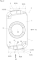
- the cutting insert 1 (hereinafter also referred to simply as "insert 1") of the embodiment includes an upper surface 3, a lower surface 5, a side surface 7, an upper cutting edge 9, a lower cutting edge 11, and a through hole 13 as shown in FIGs. 1 to 9 .
- a material of the insert for example, cemented carbide or cermet is usable.
- WC-Co As a composition of the cemented carbide, there are, for example, WC-Co, WC-TiC-Co, and WC-TiC-TaC-Co.
- the WC-Co is produced by adding cobalt (Co) powder to tungsten carbide (WC), followed by sintering.
- the WC-TiC-Co is produced by adding titanium carbide (TiC) to WC-Co.
- TiC titanium carbide
- TaC tantalum carbide
- the cermet is a sintered composite material obtainable by compositing metal into a ceramic ingredient.
- a specific example of the cermet is one which is composed mainly of a titanium compound, such as titanium carbide (TiC) or titanium nitride (TiN).
- a surface of each of the above members constituting the insert 1 may be coated with a coating film by using chemical vapor deposition (CVD) method or physical vapor deposition (PVD) method.
- CVD chemical vapor deposition
- PVD physical vapor deposition
- a composition of the coating film there are, for example, titanium carbide (TiC), titanium nitride (TiN), titanium carbonitride (TiCN), and alumina (Al 2 O 3 ).
- the upper surface 3 has a polygonal shape having rotational symmetry, and is formed into an approximately rectangular shape having rotational symmetry of 180° in the present embodiment as shown in FIG. 2 .
- the rectangular-shaped upper surface 3 includes a plurality of upper corner parts and a plurality of upper side parts located between the upper corner parts adjacent to each other.
- the upper surface 3 includes four upper corner parts and two upper side parts corresponding to short sides of the rectangular shape in the present embodiment.
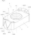
- the lower surface 5 has a polygonal shape having rotational symmetry corresponding to the upper surface 3. Similarly to the upper surface 3, the lower surface 5 is formed into an approximately rectangular shape having rotational symmetry of 180° in the present embodiment as shown in FIG. 5 .
- the rectangular-shaped lower surface 5 includes a plurality of lower corner parts and a plurality of lower side parts located between the lower corner parts adjacent to each other. Specifically, the lower surface 5 includes four lower corner parts and two lower side parts corresponding to short sides of the rectangular shape in the present embodiment.
- the upper surface 3 and the lower surface 5 in the present embodiment have the shape with rotational symmetry.
- the center of the rotational symmetry corresponds to the center of the upper surface 3 or the center of the lower surface 5.
- the lower surface 5 has the polygonal shape corresponding to the upper surface 3 and has the same size, an entire outer edge of the upper surface 3 and an entire outer edge of the lower surface 5 are not located in an overlapped manner when seen through from above.
- the center of the upper surface 3 and the center of the lower surface 5 are located in an overlapping manner, and the upper corner parts and the lower corner parts are located in an overlapping manner, whereas the upper side parts and the lower side parts are not located in a completely overlapping manner when seen through from above.
- each of the upper corner parts on the upper surface 3 in the present embodiment is not made into a strict corner, but has a rounded shape in a top view.
- Each of the upper side parts on the upper surface 3 in the present embodiment is not made into a strict straight line, but is made into a shape that protrudes outward in a top view.
- the shapes of the upper surface 3 and the lower surface 5 are not limited to the above embodiment.
- the upper surface 3 and the lower surface 5 have an approximately square shape.
- the upper surface 3 and the lower surface 5 may have a polygonal shape, such as a triangular or hexagonal shape having rotational symmetry.
- the insert 1 of the invention includes the through hole 13 extending between the upper surface 3 and the lower surface 5.
- the through hole 13 is disposed for inserting a screw therethrough when screwing the insert 1 into the holder of a cutting tool.
- the through hole 13 is located between the center of the upper surface 3 and the center of the lower surface 5. Therefore, a central axis O1 of the through hole 13 extends vertically.
- a reference plane S that is orthogonal to the central axis O1 and located between the upper surface 3 and the lower surface 5 is set in the following.
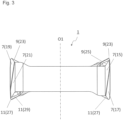
- the side surface 7 is located between the upper surface 3 and the lower surface 5, and is connected to the upper surface 3 and the lower surface 5.
- the side surface 7 includes a plurality of first surfaces 15, a plurality of second surfaces 17, a plurality of third surfaces 19 and a plurality of fourth surfaces 21.
- the upper cutting edges 9 are respectively located along the upper side parts on the upper surface 3.
- Each of the upper cutting edges 9 includes a first upper cutting edge 23 and a second upper cutting edge 25.
- the insert 1 of the present embodiment includes two first upper cutting edges 23 and two second upper cutting edges 25.
- the first upper cutting edge 23 and the second upper cutting edge 25 are in the shape of a straight line, but are not located on a straight line in a top view.
- first upper cutting edge 23 and the second upper cutting edge 25 are in the shape of the straight line in the top view, it is avoidable that a cutting load is concentrated locally at the first upper cutting edge 23 and the second upper cutting edge 25. It is therefore possible to enhance durability of the first upper cutting edge 23 and the second upper cutting edge 25.
- the first upper cutting edge 23 and the second upper cutting edge 25 are located so as to form an obtuse angle in a top view. Therefore, each of the upper side parts is in the shape that protrudes outward in the top view as described above.
- first upper cutting edge 23 and the second upper cutting edge 25 are so located, it is avoidable that a cutting load is excessively concentrated at a boundary part between the first upper cutting edge 23 and the second upper cutting edge 25. It is therefore possible to suitably use the second upper cutting edge 25 during a helical process or lapping process, while using the first upper cutting edge 23 as a major cutting edge, as described later.
- the first upper cutting edge 23 is a segment used as the major cutting edge during a cutting process of a workpiece. Upon attachment to the holder, the first upper cutting edge 23 is attached so as to depart from the workpiece as departing from the second upper cutting edge 25 adjacent to the first upper cutting edge 23.
- the second upper cutting edge 25 is a segment auxiliary used during the cutting process of the workpiece, and is used during the helical process or lapping process. Upon attachment to the holder, the second upper cutting edge 25 is attached so as to depart from the workpiece as departing from the first upper cutting edge 23 adjacent to the second upper cutting edge 25. In other words, when the insert 1 is being attached to the holder, the boundary part between the first upper cutting edge 23 and the second upper cutting edge 25 is located closest to the front end side of the holder.
- the insert 1 needs to be temporarily removed from the holder and then reattached to the holder by turning the insert 1 180° around the central axis O1. This makes it possible to use an unused other upper cutting edge 9 in the cutting process of the workpiece.
- Lower cutting edges 11 are respectively located on the lower side parts on the lower surface 5.
- Each of the lower cutting edges 11 includes a first lower cutting edge 27 and a second lower cutting edge 29. That is, the insert 1 of the present embodiment includes two first lower cutting edges 27 and two second lower cutting edges 29.
- the first lower cutting edge 27 and the second lower cutting edge 29 are in the shape of a straight line, but are not located on a straight line in a bottom view.
- first lower cutting edge 27 and the second lower cutting edge 29 are in the shape of the straight line in the bottom view, it is avoidable that a cutting load is concentrated locally at the first lower cutting edge 27 and the second lower cutting edge 29. It is therefore possible to enhance durability of the first lower cutting edge 27 and the second lower cutting edge 29.
- the first lower cutting edge 27 and the second lower cutting edge 29 are located so as to form an obtuse angle in a bottom view. Therefore, each of the lower side parts is in a shape that protrudes outward in the bottom view.
- first lower cutting edge 27 and the second lower cutting edge 29 are so located, it is avoidable that a cutting load is excessively concentrated at a boundary part between the first lower cutting edge 27 and the second lower cutting edge 29. It is therefore possible to suitably use the second lower cutting edge 29 during the helical process or lapping process, while using the first lower cutting edge 27 as the major cutting edge, as described later.
- the first lower cutting edge 27 is a segment used as the major cutting edge during the cutting process of the workpiece.
- the second lower cutting edge 29 is a segment auxiliary used during the cutting process of the workpiece, and is used during the helical process or lapping process.
- the first lower cutting edge 27 is located below the second upper cutting edge 25 and the second lower cutting edge 29 is located below the first upper cutting edge 23 in a side view of the insert 1.
- the segments of the cutting edges are located so as to ensure overlapping between the first upper cutting edge 23 and the first lower cutting edge 27 and overlapping between the second upper cutting edge 25 and the second lower cutting edge 29 when the insert 1 is turned upside down by reversing the central axis O1.
- the lower cutting edge 11 is usable in the same manner as the upper cutting edge 9 by turning the insert 1 upside down.
- a so-called honing process may be applied to a region in which the upper cutting edge 9 and the lower cutting edge 11 are located. That is, neither a ridge line along which the upper surface 3 and the side surface 7 intersect each other, nor a ridge line along which the lower surface 5 and the side surface 7 intersect each other needs to be a strict line form formed by the intersection of the two surfaces.
- the line-shaped ridge lines cause strength deterioration of the upper cutting edge 9 and the lower cutting edge 11. Therefore, round honing is carried out to make the region into a curved surface shape.
- a maximum width of the upper surface 3 in a top view of the insert 1 of the present embodiment is 6-25 mm.
- a height from the lower surface 5 to the upper surface 3 is 1-10 mm.
- the height from the lower surface 5 to the upper surface 3 denotes a height in a direction parallel to the central axis O1 between an upper end of the upper surface 3 and a lower end of the lower surface 5.
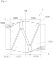
- the side surface 7 includes the first surfaces 15, the second surfaces 17, the third surfaces 19, and the fourth surfaces 21 as described above.
- the first surface 15 is a region of the side surface 7 which extends downward from the second upper cutting edge 25.
- the second surface 17 is a region of the side surface 7 which extends upward from the first lower cutting edge 27.
- the third surface 19 is a region of the side surface 7 which extends downward from the first upper cutting edge 23.
- the fourth surface 21 is a region of the side surface 7 which extends upward from the second lower cutting edge 29.
- the first surface 15, the second surface 17, the third surface 19 and the fourth surface 21 are sequentially located side by side in a side view.
- the first surface 15 is located leftmost, and the second surface 17 is located on the right side of the first surface 15.
- the third surface 19 is located on the right side of the second surface 17, and the fourth surface 21 is located on the right side of the third surface 19.
- Each of the first surface 15, the second surface 17, the third surface 19 and the fourth surface 21 in the present embodiment is a flat surface.
- the first to fourth surfaces made up of the flat surfaces ensures a stable fixing of the insert 1 to the holder when attaching the insert 1 to the holder.
- the region of the side surface 7 located between the second upper cutting edge 25 and the first lower cutting edge 27 is made up of the first surface 15 and the second surface 17, instead of a single flat surface region.
- the region located between the second lower cutting edge 29 and the first upper cutting edge 23 is also made up of the third surface 19 and the fourth surface 21, instead of a single flat surface region.
- the first surface 15 is located along the central axis O1 of the through hole 13, and is parallel to the central axis O1 of the through hole 13 in the present embodiment.
- the fourth surface 21 is located along the central axis O1 of the through hole 13, and is parallel to the central axis O1 of the through hole 13 in the present embodiment.
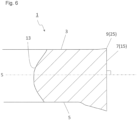
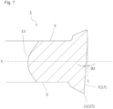
- the second surface 17 is inclined so as to further depart from the central axis O1 than the first surface 15 as going from the lower surface 5 toward the upper surface 3. Specifically, the second surface 17 is inclined at an angle ⁇ 2 with respect to the central axis O1 in a sectional view. A ridge line is formed between the first surface 15 and the second surface 17 because the first surface 15 and the second surface 17 are located as described above.
- a straight line L orthogonal to the reference plane S and parallel to the central axis O1 is indicated, the central axis O1 is replaced with the straight line L, and the angle ⁇ 2 is indicated by an inclination angle with respect to the straight line L.
- the angle ⁇ 2 is settable to, for example, approximately 1-10°.
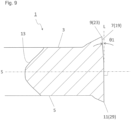
- the third surface 19 is inclined so as to further depart from the central axis O1 than the fourth surface 21 as going from the upper surface 3 toward the lower surface 5. Specifically, the third surface 19 is inclined at an angle ⁇ 1 with respect to the central axis O1 in a sectional view. A ridge line is formed between the third surface 19 and the fourth surface 21 because the third surface 19 and the fourth surface 21 are located as described above.
- a straight line L orthogonal to the reference plane S and parallel to the central axis O1 is indicated, the central axis O1 is replaced with the straight line L, and the angle ⁇ 1 is indicated by an inclination angle with respect to the straight line L.
- the angle ⁇ 1 is settable to, for example, approximately 1-10°.
- the angle ⁇ 1 is preferably identical to the angle ⁇ 2.
- the second surface 17 that is the region of the side surface 7 corresponding to the first lower cutting edge 27, and the third surface 19 that is the region of the side surface 7 corresponding to the first upper cutting edge 23 are located so as to depart from the central axis O1 as departing from the cutting edge.
- the first lower cutting edge 27 and the first upper cutting edge 23 function as the major cutting edge during the cutting process.
- the second surface 17 and the third surface 19 are configured as described above, thereby making it possible to enhance strength of the first lower cutting edge 27 and the first upper cutting edge 23 which are subjected to a relatively large load.
- the side surface 7 in the present embodiment also includes the first surface 15 corresponding to the second upper cutting edge 25, and the fourth surface 21 corresponding to the second lower cutting edge 29.
- the first surface 15 and the fourth surface 21 are parallel to the central axis O1 in a sectional view, and are therefore orthogonal to the reference plane S.
- the region of the side surface 7 which is located between the second upper cutting edge 25 and the first lower cutting edge 27 is formed by a single surface region, it follows that on the basis of the first lower cutting edge 27, the surface region departs from the central axis O1 as departing from the first lower cutting edge 27.
- the surface region approaches the central axis O1 as departing from the second upper cutting edge 25. This can degrade strength of the second upper cutting edge 25.
- the region of the side surface 7 which is located between the second lower cutting edge 29 and the first upper cutting edge 23 is made up of a single surface region, it follows that on the basis of the first upper cutting edge 23, the surface region departs from the central axis O1 as departing from the first upper cutting edge 23. Inevitably on the basis of the second lower cutting edge 29, the surface region approaches the central axis O1 as departing from the second lower cutting edge 29. This can degrade strength of the second lower cutting edge 29.
- the first surface 15 in the present embodiment has a surface configuration separately from the second surface 17 so that a ridge line is formed therebetween. This makes it possible to enhance the strength of the second upper cutting edge 25 while enhancing the strength of the first lower cutting edge 27.
- the fourth surface 21 in the present embodiment has a surface configuration separately from the third surface 19 so that a ridge line is formed therebetween. This makes it possible to enhance the strength of the second lower cutting edge 29 while enhancing the strength of the first upper cutting edge 23.
- the second surface 17 is inclined so as to depart from the central axis O1 as going from the lower surface 5 toward the upper surface 3, while the third surface 19 is inclined so as to depart from the central axis O1 as going from the upper surface 3 toward the lower surface 5. Accordingly, a ridge line is also formed between the second surface 17 and the third surface 19.
- the insert 1 of the present embodiment includes the upper cutting edges 9 and the lower cutting edges 11, and one of these cutting edge regions is used during a cutting process. For example, when one of the upper cutting edges 9 is used during a cutting process, the rest of the upper cutting edges 9 is not used during the cutting process. A region of the side surface 7 corresponding to each of the upper cutting edges 9 not being used during the cutting process is used as a constraining surface against the holder configured to attach the insert 1 thereto.
- a force is applied to the upper cutting edge 9 being used during the cutting process, in a direction from the upper surface toward the lower surface.
- the insert 1 is fixed to the holder by a screw fitted into the through hole 13. Therefore, a force is apt to be applied to the location of the upper cutting edge 9 not being used during the cutting process, in a direction from the lower surface toward the upper surface.
- the first surface 15 and the fourth surface 21 are parallel to the central axis O1 in a cross section including the central axis O1 of the through hole 13. This makes it possible for the holder to stably fix the insert 1 even on the first surface 15 and the fourth surface 21.
- the insert 1 is stably fixable on the first surface 15 and the fourth surface 21 for the same reason.
- the first surface 15 and the fourth surface 21 are connected to the upper surface 3 and the lower surface 5. It is therefore possible to increase an area of each of the first surface 15 and the fourth surface 21, thereby ensuring that the insert 1 is stably fixable on the first surface 15 and the fourth surface 21.
- the second surface 17 has a smaller width in the direction orthogonal to the central axis O1 as going from the lower surface 5 toward the upper surface 3 in a side view.
- the third surface 19 has a smaller width in the direction orthogonal to the central axis O1 as going from the upper surface 3 toward the lower surface 5 in a side view. This makes it possible to ensure a large area of each of the first surface 15 and the fourth surface 21.
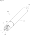
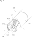
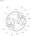
- FIGs. 10 to 12 show a state in which the insert 1 is attached via a screw 107 to an insert pocket 105 of the holder 103.
- a chain double-dashed line in FIGs. 10 and 11 indicates a rotation axis O2 of the cutting tool 101.
- the cutting tool 101 of the present embodiment includes the holder 103 having the rotation axis O2 and including a plurality of insert pockets 105 (hereinafter also referred to simply as "pockets 105") on an outer peripheral surface on a front end side of the holder 103, and the insert 1 to be attached to each of the pockets 105.
- pockets 105 hereinafter also referred to simply as "pockets 105"
- the holder 103 has an approximately columnar shape around the rotation axis O2.
- the pockets 105 are disposed on the outer peripheral surface on the front end side of the holder 103.
- the pockets 105 are portions configured to attach the insert 1 thereto, and open into the outer peripheral surface and a front end surface of the holder 103.
- the pockets 105 may be disposed at equal intervals or unequal intervals.
- the holder 103 is provided with the pockets 105 and is therefore not in a strict columnar shape.
- the inserts 1 are respectively attached to the pockets 105 disposed on the holder 103.
- the inserts 1 are attached so that at least a part of the upper cutting edge or the lower cutting edge protrudes forward beyond the front end surface of the holder 103, namely, toward the workpiece beyond the front end surface of the holder 103.
- the inserts 1 in the present embodiment are attached to the holder 103 so that a part of the first upper cutting edge and a part of the second upper cutting edge protrude beyond the front end surface of the holder 103.
- each of the inserts 1 is attached via the screw 107 to the pocket 105 in the present embodiment. That is, each of the inserts 1 is attached to the holder 103 by inserting the screw 107 into the through hole of the insert 1, and then inserting a front end of the screw 107 into a screw hole (not shown) formed in the pocket 105, and thereafter fixing the screw 107 into the screw hole.
- steel and cast iron are usable as the holder 103. Of these materials, it is particularly preferable to use high-rigidity steel.
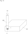
- FIGs. 13 to 15 show the method of manufacturing the machined product.
- the machined product is manufacturable by subjecting a workpiece 201 to a cutting process.
- the manufacturing method in the present embodiment includes the following steps:
- a first step is to bring the cutting tool 101 relatively near the workpiece 201 while rotating the cutting tool 101 around the rotation axis O2.
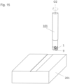
- a subsequent step is to cut the workpiece 201 by bringing the upper cutting edge 9 as a cutting edge in the cutting tool 101 into contact with the workpiece 201 as shown in FIG. 14 .
- a final step is to keep the cutting tool 101 relatively away from the workpiece 201 as shown in FIG. 15 .
- the workpiece 201 is fixed and the cutting tool 101 is brought near.
- the workpiece 201 is fixed and the cutting tool 101 is rotated around the rotation axis O2.
- the workpiece 201 is fixed and the cutting tool 101 is kept away.
- the workpiece 201 is fixed and the cutting tool 101 is moved in each of the steps during the cutting process in the manufacturing method of the present embodiment, it is, of course, not intended to limit to this embodiment.
- the workpiece 201 may be brought near the cutting tool 101.
- the workpiece 201 may be kept away from the cutting tool 101.
- the upper cutting edge being used When the upper cutting edge being used is worn away, the upper cutting edge not yet used needs to be used by rotating the insert 1 180 degrees with respect to the central axis of the through hole. When all of the upper cutting edges are worn away, the lower cutting edge needs to be used by turning the insert up and down.
- Representative examples of the material of the workpiece 201 include carbon steel, alloy steel, stainless steel, cast iron, and nonferrous metals.
Landscapes
- Engineering & Computer Science (AREA)
- Mechanical Engineering (AREA)
- Milling Processes (AREA)
- Cutting Tools, Boring Holders, And Turrets (AREA)
Claims (9)
- Schneideinsatz (1), der Folgendes umfasst:eine obere Oberfläche (3), umfassend mehrere Seitenteile;eine untere Oberfläche (5), umfassend mehrere Seitenteile;eine seitliche Oberfläche (7), befindlich zwischen der oberen Oberfläche (3) und der unteren Oberfläche (5);eine obere Schneidkante (9), die entlang eines der Seitenteile an der oberen Oberfläche (3) befindlich ist und eine erste obere Schneidkante (23) und eine zweite obere Schneidkante (25) umfasst;eine untere Schneidkante (11), die entlang eines der Seitenteile an der unteren Oberfläche (5) befindlich ist und eine erste untere Schneidkante (27) und eine zweite untere Schneidkante (29) umfasst; undein Durchgangsloch (13), das sich zwischen der oberen Oberfläche (3) und der unteren Oberfläche (5) erstreckt,wobei die erste untere Schneidkante (27) unter der zweiten oberen Schneidkante (25) befindlich ist und die zweite untere Schneidkante (29) unter der ersten oberen Schneidkante (23) befindlich ist, sodass, wenn der Einsatz (1) durch Umkehren der mittleren Achse (O1) umgedreht wird, sich die erste obere Schneidkante (23) und die erste untere Schneidkante (27) überlappen und sich die zweite obere Schneidkante (25) und die zweite untere Schneidkante (29) überlappen,wobei die erste obere Schneidkante (23) und die zweite obere Schneidkante (25) individuell in einer Draufsicht in einer Linienform sind, wobei die erste untere Schneidkante (27) und die zweite untere Schneidkante (29) individuell in einer Unteransicht in einer geraden Linienform sind, wobei die obere Schneidkante (9) in einer herausragenden Form ist, die einen stumpfen Winkel aufweist, der in der Draufsicht durch die erste obere Schneidkante (23) und die zweite obere Schneidkante (25) gebildet ist, und wobei die untere Schneidkante (11) in einer herausragenden Form ist, die einen stumpfen Winkel aufweist, der in der Unteransicht durch die erste untere Schneidkante (27) und die zweite untere Schneidkante (29) gebildet ist, dadurch gekennzeichnet, dassdie seitliche Oberfläche (7) eine erste Oberfläche (15), die sich von der zweiten oberen Schneidkante (25) nach unten erstreckt, eine zweite Oberfläche (17), die sich von der ersten unteren Schneidkante (27) nach oben erstreckt, eine dritte Oberfläche (19), die sich von der ersten oberen Schneidkante (23) nach unten erstreckt, und eine vierte Oberfläche (21), die sich von der zweiten unteren Schneidkante (29) nach oben erstreckt, umfasst,wobei die erste Oberfläche (15) und die vierte Oberfläche (21) parallel zu einer mittleren Achse (O1) des Durchgangslochs (13) sind,wobei die zweite Oberfläche (17) geneigt ist, um sich von der mittleren Achse (O1) zu entfernen, wenn sie von der unteren Oberfläche (5) zur oberen Oberfläche (3) verläuft,wobei die dritte Oberfläche (19) geneigt ist, um sich von der mittleren Achse (O1) zu entfernen, wenn sie von der oberen Oberfläche (3) zur unteren Oberfläche (5) verläuft.
- Schneideinsatz (1) nach Anspruch 1, wobei die erste Oberfläche (15) und die vierte Oberfläche (21) mit der oberen Oberfläche (3) und der unteren Oberfläche (5) verbunden sind.
- Schneideinsatz (1) nach Anspruch 1 oder 2,wobei die zweite Oberfläche (17) in einer Richtung orthogonal zur mittleren Achse (O1) eine kleinere Breite aufweist, wenn sie von der unteren Oberfläche (5) zur oberen Oberfläche (3) verläuft, undwobei die dritte Oberfläche (19) in einer Richtung orthogonal zur mittleren Achse (O1) eine kleinere Breite aufweist, wenn sie von der oberen Oberfläche (3) zur unteren Oberfläche (5) verläuft.
- Schneideinsatz (1) nach einem der Ansprüche 1 bis 3, wobei jede aus der ersten Oberfläche (15), der zweiten Oberfläche (17), der dritten Oberfläche (19) und der vierten Oberfläche (21) eine flache Oberfläche ist.
- Schneideinsatz (1) nach einem der Ansprüche 1 bis 4, wobei die dritte Oberfläche (19) mit der zweiten Oberfläche (17) verbunden ist, um eine Kammlinie zwischen der zweiten Oberfläche (17) und der dritten Oberfläche (19) zu bilden.
- Schneideinsatz (1) nach einem der Ansprüche 1 bis 5, wobei die dritte Oberfläche (19) in einem Winkel θ1 bezüglich der mittleren Achse (O1) geneigt ist,wobei die zweite Oberfläche (17) in einem Winkel θ2 bezüglich der mittleren Achse (O1) geneigt ist, undwobei der Winkel θ1 gleich dem Winkel θ2 ist.
- Schneidwerkzeug (101), das Folgendes umfasst:einen Halter (103) mit einer Einsatztasche (105) an einem vorderen Ende des Halters (103); undeinen Schneideinsatz (1) nach einem der Ansprüche 1 bis 6, wobei der Schneideinsatz (1) an der Einsatztasche (105) befestigt wird, sodass zumindest ein Teil der oberen Schneidkante (9) oder der unteren Schneidkante (11) aus dem Halter (103) herausragt.
- Schneidwerkzeug (101) nach Anspruch 7,
wobei sich ein Begrenzungsteil zwischen der ersten oberen Schneidkante (23) und der zweiten oberen Schneidkante (25) am nächsten zum vorderen Ende des Halters (103) befindet. - Verfahren zur Herstellung eines bearbeiteten Produkts , das Folgendes umfasst:Rotieren des Schneidwerkzeugs (101) nach Anspruch 7 oder 8;Inkontaktbringen der oberen Schneidkante (9) oder der unteren Schneidkante (11) im rotierenden Schneidwerkzeug (101) mit einem Werkstück (201); undBewegen des Schneidwerkzeugs (101) weg vom Werkstück (201).
Applications Claiming Priority (3)
| Application Number | Priority Date | Filing Date | Title |
|---|---|---|---|
| JP2014196026 | 2014-09-26 | ||
| PCT/JP2015/077221 WO2016047795A1 (ja) | 2014-09-26 | 2015-09-26 | 切削インサート、切削工具及び切削加工物の製造方法 |
| EP15844837.3A EP3199282B1 (de) | 2014-09-26 | 2015-09-26 | Schneideinsatz, schneidwerkzeug sowie verfahren zur herstellung eines zerschnittenen artikels |
Related Parent Applications (1)
| Application Number | Title | Priority Date | Filing Date |
|---|---|---|---|
| EP15844837.3A Division EP3199282B1 (de) | 2014-09-26 | 2015-09-26 | Schneideinsatz, schneidwerkzeug sowie verfahren zur herstellung eines zerschnittenen artikels |
Publications (3)
| Publication Number | Publication Date |
|---|---|
| EP3822011A1 EP3822011A1 (de) | 2021-05-19 |
| EP3822011B1 true EP3822011B1 (de) | 2024-05-08 |
| EP3822011C0 EP3822011C0 (de) | 2024-05-08 |
Family
ID=55581310
Family Applications (2)
| Application Number | Title | Priority Date | Filing Date |
|---|---|---|---|
| EP15844837.3A Active EP3199282B1 (de) | 2014-09-26 | 2015-09-26 | Schneideinsatz, schneidwerkzeug sowie verfahren zur herstellung eines zerschnittenen artikels |
| EP20182516.3A Active EP3822011B1 (de) | 2014-09-26 | 2015-09-26 | Schneideinsatz, schneidwerkzeug und verfahren zur herstellung eines bearbeiteten produkts |
Family Applications Before (1)
| Application Number | Title | Priority Date | Filing Date |
|---|---|---|---|
| EP15844837.3A Active EP3199282B1 (de) | 2014-09-26 | 2015-09-26 | Schneideinsatz, schneidwerkzeug sowie verfahren zur herstellung eines zerschnittenen artikels |
Country Status (5)
| Country | Link |
|---|---|
| US (3) | US10010952B2 (de) |
| EP (2) | EP3199282B1 (de) |
| JP (1) | JP6343016B2 (de) |
| CN (1) | CN106715015B (de) |
| WO (1) | WO2016047795A1 (de) |
Families Citing this family (26)
| Publication number | Priority date | Publication date | Assignee | Title |
|---|---|---|---|---|
| WO2015037617A1 (ja) * | 2013-09-11 | 2015-03-19 | 日立ツール株式会社 | 刃先交換式回転切削工具及びそれに用いるインサート |
| WO2015129769A1 (ja) * | 2014-02-26 | 2015-09-03 | 株式会社タンガロイ | 切削インサートおよび切削工具 |
| WO2015199031A1 (ja) * | 2014-06-27 | 2015-12-30 | 京セラ株式会社 | 切削インサート、切削工具及び切削加工物の製造方法 |
| KR101469135B1 (ko) * | 2014-07-08 | 2014-12-04 | 한국야금 주식회사 | 절삭 인서트 및 이를 장착한 절삭 공구 |
| CN106715015B (zh) * | 2014-09-26 | 2018-09-28 | 京瓷株式会社 | 切削镶刀、切削工具以及切削加工物的制造方法 |
| EP3072616B1 (de) * | 2015-03-25 | 2018-10-10 | Sandvik Intellectual Property AB | Schneideinsatz und fräswerkzeug |
| EP3351328B1 (de) * | 2015-09-15 | 2024-09-04 | Mitsubishi Materials Corporation | Schneideinsatz und schneidwerkzeug mit auswechselbarer klinge |
| EP3199284B1 (de) * | 2016-01-27 | 2018-12-12 | Pramet Tools, S.R.O. | Wendeschneidplatte für einen schaftfräser und mit solch einer schneidplatte ausgestatteter schaftfräser |
| JP6994035B2 (ja) * | 2017-07-26 | 2022-01-14 | 京セラ株式会社 | 切削インサート、切削工具及び切削加工物の製造方法 |
| US10987741B2 (en) * | 2017-07-27 | 2021-04-27 | Kyocera Corporation | Cutting insert, cutting tool, and method for manufacturing machined product |
| JP7116730B2 (ja) | 2017-08-23 | 2022-08-10 | 京セラ株式会社 | インサート |
| KR102193809B1 (ko) * | 2017-11-02 | 2020-12-22 | 가부시키가이샤 몰디노 | 절삭 인서트 및 날끝 교환식 절삭 공구 |
| KR102015290B1 (ko) * | 2017-11-14 | 2019-08-28 | 한국야금 주식회사 | 절삭 인서트 및 이를 장착한 절삭 공구 |
| EP3556498B1 (de) * | 2018-04-16 | 2021-02-17 | Seco Tools Ab | Schneideeinsatz und fräswerkzeug |
| JP6507355B1 (ja) | 2018-06-19 | 2019-05-08 | 株式会社タンガロイ | 切削インサート及び切削工具 |
| CN112888520B (zh) * | 2018-10-23 | 2024-04-19 | 京瓷株式会社 | 切削刀片、切削刀具以及切削加工物的制造方法 |
| WO2020090738A1 (ja) * | 2018-10-30 | 2020-05-07 | 京セラ株式会社 | 切削インサート、切削工具及び切削加工物の製造方法 |
| US12325078B2 (en) * | 2020-03-25 | 2025-06-10 | Kyocera Corporation | Cutting insert, cutting tool, and method for manufacturing machined product |
| JP7344168B2 (ja) * | 2020-03-25 | 2023-09-13 | 京セラ株式会社 | 切削インサート、切削工具及び切削加工物の製造方法 |
| JP7480291B2 (ja) * | 2020-06-01 | 2024-05-09 | 京セラ株式会社 | 切削インサート、切削工具及び切削加工物の製造方法 |
| WO2021246283A1 (ja) * | 2020-06-03 | 2021-12-09 | 京セラ株式会社 | 切削インサート、切削工具及び切削加工物の製造方法 |
| JP7011689B1 (ja) | 2020-08-11 | 2022-01-27 | 株式会社タンガロイ | 切削インサート及び回転切削工具 |
| EP3964314A1 (de) * | 2020-09-02 | 2022-03-09 | AB Sandvik Coromant | Schneideinsatz und fräswerkzeug mit hohem vorschub |
| JP6855024B1 (ja) * | 2020-10-02 | 2021-04-07 | 株式会社タンガロイ | 切削インサートおよびこれを備えた切削工具 |
| US20240326140A1 (en) * | 2023-03-28 | 2024-10-03 | Kennametal Inc. | Double-sided, indexable cutting insert with high ramping capability and cutting tool therefor |
| CN119457220B (zh) * | 2025-01-14 | 2025-07-22 | 赣州澳克泰工具技术有限公司 | 一种双面切削刀片及切削刀具 |
Family Cites Families (26)
| Publication number | Priority date | Publication date | Assignee | Title |
|---|---|---|---|---|
| GB940460A (en) * | 1960-04-06 | 1963-10-30 | Fagersta Bruks Ab | Improvements relating to metal cutters and metal cutting |
| JPS5112154B2 (de) * | 1972-02-17 | 1976-04-16 | ||
| SE382769B (sv) * | 1974-05-24 | 1976-02-16 | Seco Tools Ab | Vendsker for fresverktyg |
| US4140431A (en) | 1977-11-18 | 1979-02-20 | Kennametal Inc. | Cutting insert |
| US5188489A (en) * | 1991-05-31 | 1993-02-23 | Kennametal Inc. | Coated cutting insert |
| JP3269245B2 (ja) * | 1994-03-09 | 2002-03-25 | 三菱マテリアル株式会社 | スローアウェイチップ及び切削工具 |
| SE515070C2 (sv) * | 1999-10-22 | 2001-06-05 | Sandvik Ab | Dubbelnegativt skär till verktyg för spånavskiljande bearbetning |
| JP3952853B2 (ja) * | 2002-05-24 | 2007-08-01 | 三菱マテリアル株式会社 | スローアウェイチップ |
| IL182343A0 (en) | 2007-04-01 | 2007-07-24 | Iscar Ltd | Cutting insert and tool for milling and ramping at high feed rates |
| US20100266353A1 (en) * | 2007-05-24 | 2010-10-21 | Wolfgang Zitzlaff | Cutting insert comprising a stabilised double-sided facet |
| HUE042918T2 (hu) * | 2008-04-14 | 2019-07-29 | Taegu Tec Ltd | Cserélhetõ betétkés |
| US8834075B2 (en) | 2008-06-13 | 2014-09-16 | Taegutec, Ltd. | Cutting insert |
| JP5007853B2 (ja) * | 2009-04-02 | 2012-08-22 | 株式会社タンガロイ | 切削用インサートおよび刃先交換式切削工具 |
| JP2013006221A (ja) * | 2009-10-13 | 2013-01-10 | Mitsubishi Materials Corp | 切削インサート及び刃先交換式回転工具 |
| US8449230B2 (en) | 2010-08-13 | 2013-05-28 | Ingersoll Cutting Tool Company | Cutting insert having concave clearance depressions formed on corner side surfaces |
| US9770767B2 (en) * | 2011-05-31 | 2017-09-26 | Kyocera Corporation | Cutting insert, cutting tool, and method of manufacturing machined product using the same |
| DE102011105978B4 (de) * | 2011-06-29 | 2022-06-23 | Kennametal Inc. | Wendeschneidplatte sowie Plan-Eckfräser mit Wendeschneidplatte |
| JP5701385B2 (ja) * | 2011-06-30 | 2015-04-15 | 京セラ株式会社 | 切削インサートおよび切削工具ならびにそれを用いた切削加工物の製造方法 |
| EP2559509B1 (de) * | 2011-08-16 | 2014-12-31 | Seco Tools Ab | Indexierbarer, doppelseitiger Schneideinsatz und Schneidwerkzeug mit einem derartigen Einsatz |
| JP5906976B2 (ja) * | 2011-10-04 | 2016-04-20 | 三菱マテリアル株式会社 | 切削インサートおよび刃先交換式切削工具 |
| US9272342B2 (en) * | 2011-10-31 | 2016-03-01 | Kyocera Corporation | Cutting insert, cutting tool, and method of producing machined product using the same |
| EP2596889B1 (de) * | 2011-11-23 | 2017-04-26 | Sandvik Intellectual Property AB | Schneideinsatz und Fräser |
| JP5904346B2 (ja) * | 2012-12-05 | 2016-04-13 | 株式会社タンガロイ | 切削工具用ボデーおよび該ボデーを適用した切削工具 |
| AT14072U1 (de) * | 2014-02-04 | 2015-04-15 | Ceratizit Luxembourg S R L | Doppelseitiger Frässchneideinsatz und Fräswerkzeug |
| CN106715015B (zh) * | 2014-09-26 | 2018-09-28 | 京瓷株式会社 | 切削镶刀、切削工具以及切削加工物的制造方法 |
| CN107073604B (zh) * | 2014-11-27 | 2019-07-30 | 株式会社泰珂洛 | 切削刀片及刀头更换式旋转切削工具 |
-
2015
- 2015-09-26 CN CN201580050040.XA patent/CN106715015B/zh active Active
- 2015-09-26 JP JP2016550426A patent/JP6343016B2/ja active Active
- 2015-09-26 US US15/511,808 patent/US10010952B2/en active Active
- 2015-09-26 WO PCT/JP2015/077221 patent/WO2016047795A1/ja not_active Ceased
- 2015-09-26 EP EP15844837.3A patent/EP3199282B1/de active Active
- 2015-09-26 EP EP20182516.3A patent/EP3822011B1/de active Active
-
2018
- 2018-06-13 US US16/007,451 patent/US10456845B2/en active Active
-
2019
- 2019-10-22 US US16/660,220 patent/US20200047264A1/en not_active Abandoned
Also Published As
| Publication number | Publication date |
|---|---|
| US20170291231A1 (en) | 2017-10-12 |
| EP3199282A4 (de) | 2018-05-23 |
| WO2016047795A1 (ja) | 2016-03-31 |
| JP6343016B2 (ja) | 2018-06-13 |
| EP3199282A1 (de) | 2017-08-02 |
| CN106715015A (zh) | 2017-05-24 |
| EP3822011C0 (de) | 2024-05-08 |
| JPWO2016047795A1 (ja) | 2017-06-22 |
| US20190015910A1 (en) | 2019-01-17 |
| CN106715015B (zh) | 2018-09-28 |
| US20200047264A1 (en) | 2020-02-13 |
| US10010952B2 (en) | 2018-07-03 |
| EP3822011A1 (de) | 2021-05-19 |
| US10456845B2 (en) | 2019-10-29 |
| EP3199282B1 (de) | 2020-07-29 |
Similar Documents
| Publication | Publication Date | Title |
|---|---|---|
| EP3822011B1 (de) | Schneideinsatz, schneidwerkzeug und verfahren zur herstellung eines bearbeiteten produkts | |
| US10245659B2 (en) | Cutting insert, cutting tool, and method for manufacturing machined product | |
| US10058938B2 (en) | Cutting insert, cutting tool, and method of producing machined product | |
| EP3124148B1 (de) | Schneideinsatz, schneidwerkzeug und verfahren zur herstellung eines bearbeiteten produktes | |
| US10124426B2 (en) | Cutting insert, cutting tool, and method of manufacturing machined product | |
| EP3195962B1 (de) | Schneideinsatz, schneidwerkzeug und herstellungsverfahren für zerspanten artikel | |
| US10478901B2 (en) | Cutting insert, cutting tool, and method of manufacturing machined product | |
| EP3015205B1 (de) | Schneideinsatz, schneidwerkzeug und herstellungsverfahren für geschnittenes werkstück | |
| US10239125B2 (en) | Cutting insert, cutting tool, and method for manufacturing machined product using same | |
| US10919095B2 (en) | Cutting insert, cutting tool, and method of manufacturing machined product | |
| JP6711842B2 (ja) | 切削インサート、切削工具及び切削加工物の製造方法 | |
| US20180169767A1 (en) | Cutting insert, cutting tool, and method of manufacturing machined product using the same | |
| US11207741B2 (en) | Cutting insert, cutting tool and method for manufacturing machined product | |
| US20180178295A1 (en) | Cutting tool and method for manufacturing cut workpiece | |
| JP6685532B2 (ja) | 切削インサート、切削工具及び切削加工物の製造方法 | |
| JP6892369B2 (ja) | 切削インサート、切削工具及び切削加工物の製造方法 | |
| US11628504B2 (en) | Cutting insert, cutting tool, and method for manufacturing machined product |
Legal Events
| Date | Code | Title | Description |
|---|---|---|---|
| PUAI | Public reference made under article 153(3) epc to a published international application that has entered the european phase |
Free format text: ORIGINAL CODE: 0009012 |
|
| STAA | Information on the status of an ep patent application or granted ep patent |
Free format text: STATUS: REQUEST FOR EXAMINATION WAS MADE |
|
| 17P | Request for examination filed |
Effective date: 20200626 |
|
| AC | Divisional application: reference to earlier application |
Ref document number: 3199282 Country of ref document: EP Kind code of ref document: P |
|
| AK | Designated contracting states |
Kind code of ref document: A1 Designated state(s): AL AT BE BG CH CY CZ DE DK EE ES FI FR GB GR HR HU IE IS IT LI LT LU LV MC MK MT NL NO PL PT RO RS SE SI SK SM TR |
|
| RBV | Designated contracting states (corrected) |
Designated state(s): AL AT BE BG CH CY CZ DE DK EE ES FI FR GB GR HR HU IE IS IT LI LT LU LV MC MK MT NL NO PL PT RO RS SE SI SK SM TR |
|
| P01 | Opt-out of the competence of the unified patent court (upc) registered |
Effective date: 20230505 |
|
| GRAP | Despatch of communication of intention to grant a patent |
Free format text: ORIGINAL CODE: EPIDOSNIGR1 |
|
| STAA | Information on the status of an ep patent application or granted ep patent |
Free format text: STATUS: GRANT OF PATENT IS INTENDED |
|
| INTG | Intention to grant announced |
Effective date: 20240123 |
|
| GRAS | Grant fee paid |
Free format text: ORIGINAL CODE: EPIDOSNIGR3 |
|
| GRAA | (expected) grant |
Free format text: ORIGINAL CODE: 0009210 |
|
| STAA | Information on the status of an ep patent application or granted ep patent |
Free format text: STATUS: THE PATENT HAS BEEN GRANTED |
|
| AC | Divisional application: reference to earlier application |
Ref document number: 3199282 Country of ref document: EP Kind code of ref document: P |
|
| AK | Designated contracting states |
Kind code of ref document: B1 Designated state(s): AL AT BE BG CH CY CZ DE DK EE ES FI FR GB GR HR HU IE IS IT LI LT LU LV MC MK MT NL NO PL PT RO RS SE SI SK SM TR |
|
| REG | Reference to a national code |
Ref country code: GB Ref legal event code: FG4D |
|
| REG | Reference to a national code |
Ref country code: CH Ref legal event code: EP |
|
| REG | Reference to a national code |
Ref country code: DE Ref legal event code: R096 Ref document number: 602015088675 Country of ref document: DE |
|
| REG | Reference to a national code |
Ref country code: IE Ref legal event code: FG4D |
|
| U01 | Request for unitary effect filed |
Effective date: 20240522 |
|
| P04 | Withdrawal of opt-out of the competence of the unified patent court (upc) registered |
Effective date: 20240528 |
|
| U07 | Unitary effect registered |
Designated state(s): AT BE BG DE DK EE FI FR IT LT LU LV MT NL PT SE SI Effective date: 20240603 |
|
| U20 | Renewal fee for the european patent with unitary effect paid |
Year of fee payment: 10 Effective date: 20240807 |
|
| PG25 | Lapsed in a contracting state [announced via postgrant information from national office to epo] |
Ref country code: IS Free format text: LAPSE BECAUSE OF FAILURE TO SUBMIT A TRANSLATION OF THE DESCRIPTION OR TO PAY THE FEE WITHIN THE PRESCRIBED TIME-LIMIT Effective date: 20240908 |
|
| PG25 | Lapsed in a contracting state [announced via postgrant information from national office to epo] |
Ref country code: HR Free format text: LAPSE BECAUSE OF FAILURE TO SUBMIT A TRANSLATION OF THE DESCRIPTION OR TO PAY THE FEE WITHIN THE PRESCRIBED TIME-LIMIT Effective date: 20240508 |
|
| PG25 | Lapsed in a contracting state [announced via postgrant information from national office to epo] |
Ref country code: GR Free format text: LAPSE BECAUSE OF FAILURE TO SUBMIT A TRANSLATION OF THE DESCRIPTION OR TO PAY THE FEE WITHIN THE PRESCRIBED TIME-LIMIT Effective date: 20240809 |
|
| PG25 | Lapsed in a contracting state [announced via postgrant information from national office to epo] |
Ref country code: ES Free format text: LAPSE BECAUSE OF FAILURE TO SUBMIT A TRANSLATION OF THE DESCRIPTION OR TO PAY THE FEE WITHIN THE PRESCRIBED TIME-LIMIT Effective date: 20240508 |
|
| PG25 | Lapsed in a contracting state [announced via postgrant information from national office to epo] |
Ref country code: PL Free format text: LAPSE BECAUSE OF FAILURE TO SUBMIT A TRANSLATION OF THE DESCRIPTION OR TO PAY THE FEE WITHIN THE PRESCRIBED TIME-LIMIT Effective date: 20240508 |
|
| PG25 | Lapsed in a contracting state [announced via postgrant information from national office to epo] |
Ref country code: PL Free format text: LAPSE BECAUSE OF FAILURE TO SUBMIT A TRANSLATION OF THE DESCRIPTION OR TO PAY THE FEE WITHIN THE PRESCRIBED TIME-LIMIT Effective date: 20240508 Ref country code: NO Free format text: LAPSE BECAUSE OF FAILURE TO SUBMIT A TRANSLATION OF THE DESCRIPTION OR TO PAY THE FEE WITHIN THE PRESCRIBED TIME-LIMIT Effective date: 20240808 Ref country code: IS Free format text: LAPSE BECAUSE OF FAILURE TO SUBMIT A TRANSLATION OF THE DESCRIPTION OR TO PAY THE FEE WITHIN THE PRESCRIBED TIME-LIMIT Effective date: 20240908 Ref country code: HR Free format text: LAPSE BECAUSE OF FAILURE TO SUBMIT A TRANSLATION OF THE DESCRIPTION OR TO PAY THE FEE WITHIN THE PRESCRIBED TIME-LIMIT Effective date: 20240508 Ref country code: GR Free format text: LAPSE BECAUSE OF FAILURE TO SUBMIT A TRANSLATION OF THE DESCRIPTION OR TO PAY THE FEE WITHIN THE PRESCRIBED TIME-LIMIT Effective date: 20240809 Ref country code: ES Free format text: LAPSE BECAUSE OF FAILURE TO SUBMIT A TRANSLATION OF THE DESCRIPTION OR TO PAY THE FEE WITHIN THE PRESCRIBED TIME-LIMIT Effective date: 20240508 Ref country code: RS Free format text: LAPSE BECAUSE OF FAILURE TO SUBMIT A TRANSLATION OF THE DESCRIPTION OR TO PAY THE FEE WITHIN THE PRESCRIBED TIME-LIMIT Effective date: 20240808 |
|
| P05 | Withdrawal of opt-out of the competence of the unified patent court (upc) changed |
Free format text: CASE NUMBER: APP_31591/2024 Effective date: 20240603 |
|
| PG25 | Lapsed in a contracting state [announced via postgrant information from national office to epo] |
Ref country code: CZ Free format text: LAPSE BECAUSE OF FAILURE TO SUBMIT A TRANSLATION OF THE DESCRIPTION OR TO PAY THE FEE WITHIN THE PRESCRIBED TIME-LIMIT Effective date: 20240508 |
|
| PG25 | Lapsed in a contracting state [announced via postgrant information from national office to epo] |
Ref country code: SK Free format text: LAPSE BECAUSE OF FAILURE TO SUBMIT A TRANSLATION OF THE DESCRIPTION OR TO PAY THE FEE WITHIN THE PRESCRIBED TIME-LIMIT Effective date: 20240508 Ref country code: RO Free format text: LAPSE BECAUSE OF FAILURE TO SUBMIT A TRANSLATION OF THE DESCRIPTION OR TO PAY THE FEE WITHIN THE PRESCRIBED TIME-LIMIT Effective date: 20240508 |
|
| PG25 | Lapsed in a contracting state [announced via postgrant information from national office to epo] |
Ref country code: SM Free format text: LAPSE BECAUSE OF FAILURE TO SUBMIT A TRANSLATION OF THE DESCRIPTION OR TO PAY THE FEE WITHIN THE PRESCRIBED TIME-LIMIT Effective date: 20240508 |
|
| PG25 | Lapsed in a contracting state [announced via postgrant information from national office to epo] |
Ref country code: SM Free format text: LAPSE BECAUSE OF FAILURE TO SUBMIT A TRANSLATION OF THE DESCRIPTION OR TO PAY THE FEE WITHIN THE PRESCRIBED TIME-LIMIT Effective date: 20240508 Ref country code: SK Free format text: LAPSE BECAUSE OF FAILURE TO SUBMIT A TRANSLATION OF THE DESCRIPTION OR TO PAY THE FEE WITHIN THE PRESCRIBED TIME-LIMIT Effective date: 20240508 Ref country code: RO Free format text: LAPSE BECAUSE OF FAILURE TO SUBMIT A TRANSLATION OF THE DESCRIPTION OR TO PAY THE FEE WITHIN THE PRESCRIBED TIME-LIMIT Effective date: 20240508 Ref country code: CZ Free format text: LAPSE BECAUSE OF FAILURE TO SUBMIT A TRANSLATION OF THE DESCRIPTION OR TO PAY THE FEE WITHIN THE PRESCRIBED TIME-LIMIT Effective date: 20240508 |
|
| REG | Reference to a national code |
Ref country code: DE Ref legal event code: R097 Ref document number: 602015088675 Country of ref document: DE |
|
| PLBE | No opposition filed within time limit |
Free format text: ORIGINAL CODE: 0009261 |
|
| STAA | Information on the status of an ep patent application or granted ep patent |
Free format text: STATUS: NO OPPOSITION FILED WITHIN TIME LIMIT |
|
| 26N | No opposition filed |
Effective date: 20250211 |
|
| PG25 | Lapsed in a contracting state [announced via postgrant information from national office to epo] |
Ref country code: MC Free format text: LAPSE BECAUSE OF FAILURE TO SUBMIT A TRANSLATION OF THE DESCRIPTION OR TO PAY THE FEE WITHIN THE PRESCRIBED TIME-LIMIT Effective date: 20240508 |
|
| REG | Reference to a national code |
Ref country code: CH Ref legal event code: PL |
|
| GBPC | Gb: european patent ceased through non-payment of renewal fee |
Effective date: 20240926 |
|
| PG25 | Lapsed in a contracting state [announced via postgrant information from national office to epo] |
Ref country code: GB Free format text: LAPSE BECAUSE OF NON-PAYMENT OF DUE FEES Effective date: 20240926 |
|
| PG25 | Lapsed in a contracting state [announced via postgrant information from national office to epo] |
Ref country code: CH Free format text: LAPSE BECAUSE OF NON-PAYMENT OF DUE FEES Effective date: 20240930 |
|
| PG25 | Lapsed in a contracting state [announced via postgrant information from national office to epo] |
Ref country code: IE Free format text: LAPSE BECAUSE OF NON-PAYMENT OF DUE FEES Effective date: 20240926 |
|
| U20 | Renewal fee for the european patent with unitary effect paid |
Year of fee payment: 11 Effective date: 20250807 |
|
| PG25 | Lapsed in a contracting state [announced via postgrant information from national office to epo] |
Ref country code: CY Free format text: LAPSE BECAUSE OF FAILURE TO SUBMIT A TRANSLATION OF THE DESCRIPTION OR TO PAY THE FEE WITHIN THE PRESCRIBED TIME-LIMIT; INVALID AB INITIO Effective date: 20150926 |
|
| PG25 | Lapsed in a contracting state [announced via postgrant information from national office to epo] |
Ref country code: HU Free format text: LAPSE BECAUSE OF FAILURE TO SUBMIT A TRANSLATION OF THE DESCRIPTION OR TO PAY THE FEE WITHIN THE PRESCRIBED TIME-LIMIT; INVALID AB INITIO Effective date: 20150926 |