EP3814284B1 - Ozonated water delivery system and method of use - Google Patents
Ozonated water delivery system and method of use Download PDFInfo
- Publication number
- EP3814284B1 EP3814284B1 EP19856235.7A EP19856235A EP3814284B1 EP 3814284 B1 EP3814284 B1 EP 3814284B1 EP 19856235 A EP19856235 A EP 19856235A EP 3814284 B1 EP3814284 B1 EP 3814284B1
- Authority
- EP
- European Patent Office
- Prior art keywords
- conduit
- contacting device
- ultrapure water
- ozonated water
- delivery system
- Prior art date
- Legal status (The legal status is an assumption and is not a legal conclusion. Google has not performed a legal analysis and makes no representation as to the accuracy of the status listed.)
- Active
Links
Images



Classifications
-
- A—HUMAN NECESSITIES
- A61—MEDICAL OR VETERINARY SCIENCE; HYGIENE
- A61L—METHODS OR APPARATUS FOR STERILISING MATERIALS OR OBJECTS IN GENERAL; DISINFECTION, STERILISATION OR DEODORISATION OF AIR; CHEMICAL ASPECTS OF BANDAGES, DRESSINGS, ABSORBENT PADS OR SURGICAL ARTICLES; MATERIALS FOR BANDAGES, DRESSINGS, ABSORBENT PADS OR SURGICAL ARTICLES
- A61L2/00—Disinfection or sterilisation of materials or objects, in general; Accessories therefor
- A61L2/16—Disinfection or sterilisation of materials or objects, in general; Accessories therefor using chemical substances
- A61L2/18—Liquid substances
- A61L2/183—Ozone dissolved in a liquid
-
- B—PERFORMING OPERATIONS; TRANSPORTING
- B01—PHYSICAL OR CHEMICAL PROCESSES OR APPARATUS IN GENERAL
- B01F—MIXING, e.g. DISSOLVING, EMULSIFYING OR DISPERSING
- B01F23/00—Mixing according to the phases to be mixed, e.g. dispersing or emulsifying
- B01F23/20—Mixing gases with liquids
- B01F23/23—Mixing gases with liquids by introducing gases into liquid media, e.g. for producing aerated liquids
- B01F23/232—Mixing gases with liquids by introducing gases into liquid media, e.g. for producing aerated liquids using flow-mixing means for introducing the gases, e.g. baffles
- B01F23/2322—Mixing gases with liquids by introducing gases into liquid media, e.g. for producing aerated liquids using flow-mixing means for introducing the gases, e.g. baffles using columns, e.g. multi-staged columns
-
- B—PERFORMING OPERATIONS; TRANSPORTING
- B01—PHYSICAL OR CHEMICAL PROCESSES OR APPARATUS IN GENERAL
- B01F—MIXING, e.g. DISSOLVING, EMULSIFYING OR DISPERSING
- B01F23/00—Mixing according to the phases to be mixed, e.g. dispersing or emulsifying
- B01F23/20—Mixing gases with liquids
- B01F23/23—Mixing gases with liquids by introducing gases into liquid media, e.g. for producing aerated liquids
- B01F23/237—Mixing gases with liquids by introducing gases into liquid media, e.g. for producing aerated liquids characterised by the physical or chemical properties of gases or vapours introduced in the liquid media
- B01F23/2376—Mixing gases with liquids by introducing gases into liquid media, e.g. for producing aerated liquids characterised by the physical or chemical properties of gases or vapours introduced in the liquid media characterised by the gas being introduced
- B01F23/23761—Aerating, i.e. introducing oxygen containing gas in liquids
- B01F23/237613—Ozone
-
- B—PERFORMING OPERATIONS; TRANSPORTING
- B01—PHYSICAL OR CHEMICAL PROCESSES OR APPARATUS IN GENERAL
- B01F—MIXING, e.g. DISSOLVING, EMULSIFYING OR DISPERSING
- B01F23/00—Mixing according to the phases to be mixed, e.g. dispersing or emulsifying
- B01F23/20—Mixing gases with liquids
- B01F23/23—Mixing gases with liquids by introducing gases into liquid media, e.g. for producing aerated liquids
- B01F23/237—Mixing gases with liquids by introducing gases into liquid media, e.g. for producing aerated liquids characterised by the physical or chemical properties of gases or vapours introduced in the liquid media
- B01F23/2376—Mixing gases with liquids by introducing gases into liquid media, e.g. for producing aerated liquids characterised by the physical or chemical properties of gases or vapours introduced in the liquid media characterised by the gas being introduced
- B01F23/23762—Carbon dioxide
-
- B—PERFORMING OPERATIONS; TRANSPORTING
- B01—PHYSICAL OR CHEMICAL PROCESSES OR APPARATUS IN GENERAL
- B01F—MIXING, e.g. DISSOLVING, EMULSIFYING OR DISPERSING
- B01F23/00—Mixing according to the phases to be mixed, e.g. dispersing or emulsifying
- B01F23/20—Mixing gases with liquids
- B01F23/29—Mixing systems, i.e. flow charts or diagrams
-
- B—PERFORMING OPERATIONS; TRANSPORTING
- B01—PHYSICAL OR CHEMICAL PROCESSES OR APPARATUS IN GENERAL
- B01F—MIXING, e.g. DISSOLVING, EMULSIFYING OR DISPERSING
- B01F33/00—Other mixers; Mixing plants; Combinations of mixers
- B01F33/80—Mixing plants; Combinations of mixers
- B01F33/81—Combinations of similar mixers, e.g. with rotary stirring devices in two or more receptacles
- B01F33/811—Combinations of similar mixers, e.g. with rotary stirring devices in two or more receptacles in two or more consecutive, i.e. successive, mixing receptacles or being consecutively arranged
-
- B—PERFORMING OPERATIONS; TRANSPORTING
- B01—PHYSICAL OR CHEMICAL PROCESSES OR APPARATUS IN GENERAL
- B01F—MIXING, e.g. DISSOLVING, EMULSIFYING OR DISPERSING
- B01F35/00—Accessories for mixers; Auxiliary operations or auxiliary devices; Parts or details of general application
- B01F35/20—Measuring; Control or regulation
- B01F35/21—Measuring
- B01F35/2132—Concentration, pH, pOH, p(ION) or oxygen-demand
-
- B—PERFORMING OPERATIONS; TRANSPORTING
- B01—PHYSICAL OR CHEMICAL PROCESSES OR APPARATUS IN GENERAL
- B01F—MIXING, e.g. DISSOLVING, EMULSIFYING OR DISPERSING
- B01F35/00—Accessories for mixers; Auxiliary operations or auxiliary devices; Parts or details of general application
- B01F35/20—Measuring; Control or regulation
- B01F35/22—Control or regulation
- B01F35/221—Control or regulation of operational parameters, e.g. level of material in the mixer, temperature or pressure
- B01F35/2211—Amount of delivered fluid during a period
-
- C—CHEMISTRY; METALLURGY
- C02—TREATMENT OF WATER, WASTE WATER, SEWAGE, OR SLUDGE
- C02F—TREATMENT OF WATER, WASTE WATER, SEWAGE, OR SLUDGE
- C02F1/00—Treatment of water, waste water, or sewage
- C02F1/68—Treatment of water, waste water, or sewage by addition of specified substances, e.g. trace elements, for ameliorating potable water
-
- C—CHEMISTRY; METALLURGY
- C02—TREATMENT OF WATER, WASTE WATER, SEWAGE, OR SLUDGE
- C02F—TREATMENT OF WATER, WASTE WATER, SEWAGE, OR SLUDGE
- C02F1/00—Treatment of water, waste water, or sewage
- C02F1/72—Treatment of water, waste water, or sewage by oxidation
- C02F1/78—Treatment of water, waste water, or sewage by oxidation with ozone
-
- C—CHEMISTRY; METALLURGY
- C02—TREATMENT OF WATER, WASTE WATER, SEWAGE, OR SLUDGE
- C02F—TREATMENT OF WATER, WASTE WATER, SEWAGE, OR SLUDGE
- C02F2103/00—Nature of the water, waste water, sewage or sludge to be treated
- C02F2103/02—Non-contaminated water, e.g. for industrial water supply
- C02F2103/04—Non-contaminated water, e.g. for industrial water supply for obtaining ultra-pure water
-
- C—CHEMISTRY; METALLURGY
- C02—TREATMENT OF WATER, WASTE WATER, SEWAGE, OR SLUDGE
- C02F—TREATMENT OF WATER, WASTE WATER, SEWAGE, OR SLUDGE
- C02F2201/00—Apparatus for treatment of water, waste water or sewage
- C02F2201/78—Details relating to ozone treatment devices
- C02F2201/782—Ozone generators
Definitions
- ozone is used in numerous applications including semiconductor manufacturing, solar panel processing, sanitation applications, food processing, flat panel processing, and the like.
- ozone may be dissolved in deionized water.
- Ozone is highly reactive with deionized ultrapure water, thereby causing the ozone to decay in ultrapure water in seconds.
- applications, such as semiconductor fabrication applications, solar panel and flat panel fabrication require high ozone concentrations dissolved in ultrapure water.
- the rate of ozone decay increases as the concentration of ozone dissolved in deionized ultrapure water increases.
- Certain applications for example, single semiconductor wafer processing, need dissolved ozone in randomly varying liquid flow rates, which may result in varying residence times within the supply pipes, with a higher amount of ozone decay at low liquid flow rates as an additional variance in ozone decay.
- ozone decay may be triggered by the presence of hydroxide-ions and peroxides normally found in trace amounts in industrially-used ultrapure water. As a consequence, ozone decay may vary between fabrication locations and/or sites due to variations in the concentration of these impurities within the ultrapure water supplied to different locations.
- FIG. 1 shows an example of an ozonated water delivery system presently used in semiconductor fabrication applications.
- the ozonated water delivery system 1 includes a contacting device 3 in fluid communication with an ultrapure water source 5 (hereinafter UPW source 5) via an ultrapure water source conduit 7 (hereinafter UPW source conduit 7).
- a gas source and/or ozone generator 9 (hereinafter gas source 9) is in communication with the contacting device 3 via a gas inlet conduit 11.
- the gas mixture includes carbon dioxide (CO 2 ), ozone (O 3 ), and oxygen (O 2 ).
- One or more valve devices 13 and/or indicators are used to safely separate water from the gas mixture and prevent a backflow of water, gas, or both into the gas source 9.
- the gas mixture from gas source 9 is contacted within the contacting device 3 with the ultrapure water from the UPW source 5 using a countercurrent flow thereby resulting in some portion of ozone from the gas source 9 dissolving in the ultrapure water.
- Some carbon dioxide (CO 2 ) within the gas mixture converts into carbonic acid which lowers the concentration of the hydroxide ion.
- the carbonate ions scavenge hydroxyl radicals which effectively lowers the rate of decay of dissolved ozone in ultrapure water.
- the dissolved ozone is released or removed from the contacting device 3 to form a dissolved ozone output 17 via the dissolved ozone conduit 19.
- off gases 21, such as carbon dioxide (CO 2 ), oxygen (O 2 ), and ozone (O 3 ) may be released from the contacting device 3 via the off gas conduit 23.
- CO 2 carbon dioxide
- O 2 oxygen
- O 3 ozone
- membrane modules are commonly used for dissolving gases, such as carbon dioxide, into ultrapure water or removing residual oxygen from the ultrapure water.
- gases such as carbon dioxide
- membrane modules include plastics such as polypropylene and/or polyethylene, or similar materials which are highly sensitive to oxidizing agents like peroxides and ozone.
- carbon dioxide and ozone have different solubility. As such, the concentration of carbon dioxide within the contacting device varies considerably in some flow arrangements.
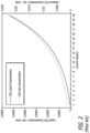
- FIG. 1 shows graphically the concentration profile of carbon dioxide in a packed column contacting device 3 using counter flow architecture.
- the abscissa in Figure 2 represents lateral sections of the packed column forming the contacting device 3 (hereinafter column sections).
- the section 1 represents the top of the column proximate to the inlet of the UPW source conduit 7 and the outlet to the off gas conduit 23.
- the section 20 represents the bottom of the column proximate to the gas inlet conduit 11 and the dissolved ozone conduit 19.
- Exemplary systems for producing ozonated water are disclosed in e.g. WO 01/28950 A1 and WO 2006/010109 A2 .
- the present application discloses various embodiments of an ozonated water delivery system capable of providing higher quantities of ultrapure water having higher concentrations of dissolved ozone therein than prior art systems.
- the ozonated water delivery system may be configured to allow for adjustment of the ozone reactivity and maintaining precise dissolved ozone measurement.
- the present application discloses an ozonated water delivery system, which includes at least one contacting device in communication with at least one ultrapure water source configured to provide ultrapure water.
- At least one ultrapure water conduit may be coupled to the ultrapure water source.
- at least one solution may be in communication with the contacting device and the ultrapure water source via the ultrapure water conduit.
- One or more gas sources containing at least one gas may be in communication with at least one of the ultrapure water source, the ultrapure water conduit, and the solution conduit. During use, the gas may be used to form at least one solution when reacted with the ultrapure water.
- At least one mixed gas conduit may be in communication with the gas source and the contacting device. The mixed gas conduit may be configured to provide at least one mixed gas to the contacting device.
- at least one ozonated water output conduit may be in communication with the contacting device.
- the present application discloses an ozonated water delivery system which includes one or more sensors configured to measure various characteristics, concentrations, flow rates, and the like of ozonated water produced by the ozonated water delivery system.
- the ozonated water delivery system may include at least one contacting device in communication with at least one ultrapure water source configured to provide ultrapure water.
- At least one ultrapure water conduit may be coupled to the ultrapure water source.
- at least one solution may be in communication with the contacting device and the ultrapure water source via the ultrapure water conduit.
- One or more gas sources containing at least one gas may be in communication with at least one of the ultrapure water source, the ultrapure water conduit, and the solution conduit.
- the gas may be used to form at least one solution when reacted with the ultrapure water.
- At least one mixed gas conduit may be in communication with the gas source and the contacting device.
- the mixed gas conduit may be configured to provide at least one mixed gas to the contacting device.
- at least one ozonated water output conduit may be in communication with the contacting device.
- One or more sensors may be positioned within the ozonated water delivery system and used to measure a variety of characteristics of the output ozonated water, such as ozone concentration, flow rate, temperature, and the like.
- the present application discloses an ozonated water delivery system which includes multiple contacting devices therein. More specifically, the present application discloses an ozonated water delivery system having a first contacting device and at least a second contacting device therein. At least one ultrapure water source may be configured to provide ultrapure water to the first contacting device. At least one ultrapure water conduit may be coupled to the ultrapure water source and the first contacting device. At least one solution conduit may be in communication with the first contacting device and the ultrapure water source via the ultrapure water conduit. At least one gas source containing at least one gas may be in communication with at least one of the ultrapure water source, the ultrapure water conduit, and the solution conduit.
- the gas may be used to form at least one solution when reacted with the ultrapure water.
- the second contacting device is in communication with the first contacting device via at least one first contacting device conduit configured to transport ozonated water outputted from the first contacting device to the second contacting device.
- At least one mixed gas conduit may be in communication with the gas source and the second contacting device.
- the mixed gas conduit may be configured to provide at least one mixed gas to the second contacting device.
- At least one off gas conduit is in communication with the second contacting device and the first contacting device, wherein the off gas conduit is configured to direct a portion of the mixed gas from the second contacting device to the first contacting device.
- At least one ozonated water output conduit may be in communication with the second contacting device.
- the present application also discloses a method of providing ozonated water. More specifically, the present application discloses a method of providing ultrapure water having higher concentrations of dissolved ozone at higher quantities than presently available.
- the method of providing ozonated water includes forming an aqueous carbon dioxide solution comprised of carbon dioxide dissolved in ultrapure water. Flowing the aqueous carbon dioxide solution into at least one contacting device. Flowing at least one mixed gas having at least a portion of which comprises ozone into the contacting device having the aqueous carbon dioxide solution flowing therein. Dissolving at least a portion of the ozone within the ultrapure water within the contacting device. Delaying the rate of ozone decay of the dissolved ozone within the ultrapure water with the carbon dioxide constituent of the aqueous carbon dioxide solution, and outputting ozonated water from the contacting device.
- the present application also discloses a method to adjust or regulate the ozone reactivity. More specifically, the present application discloses a method of measuring the ozone reactivity and control the amount of carbon dioxide gas flowing into the first contacting device in response thereto.
- the second sensor may be used to selectively regulate the flow conditions through at least one valve within the ozonated water delivery system
- the present application discloses several embodiments of a novel ozonated water delivery system.
- the novel ozonated water delivery system disclosed herein may be configured to provide ozonated water having ozone concentrations of greater than about 50 ppm.
- the novel ozonated water delivery system disclosed herein may be configured to provide ozonated water having ozone concentrations of greater than about 100 ppm.
- the novel ozonated water delivery system disclosed herein may be configured to provide ozonated water having ozone concentrations of about 50 ppm or less.
- novel ozonated water delivery systems may be configured to provide ozonated water having ozone concentrations of greater than about 50 ppm with flow rates of ultrapure water of 20 liter per minute (LPM) or greater, although those skilled in the art will appreciate that the ozonated water delivery system disclosed herein may be configured to provide ultrapure water at flow rates of less than about 20 LPM.
- the ozonated water delivery systems may be configured to provide ozonated water having ozone concentrations of greater than about 100 ppm at ultrapure water flow rates of 20 LPM or greater.
- the ozonated water delivery systems may be configured to provide ozonated water having any variety of ozone concentrations at ultrapure water flow rates of 2 LPM or greater.
- the system can be optionally configured to provide a constant ozone concentration at randomly varying ozonated water flow rates between 2 LPM and more than 20 LPM.
- FIGS 3-6 show schematic diagrams of various embodiments of a novel ozonated water delivery system.
- the ozonated water delivery system 30 disclosed herein includes at least one contacting device 32.
- a single contacting device 32 is used in the ozonated water delivery system 30 although those skilled in the art will appreciate that any number of contacting devices may be used.
- the contacting device 32 comprises a packed column architecture.
- the contacting device 32 comprises a packed column filled with tower packing.
- the contacting device 32 comprises a membrane-based device or at least one membrane module.
- the contacting device 32 may be in fluid communication with at least one deionized ultrapure water source 34 (hereinafter UPW source 34) via at least one ultrapure water conduit 36 (hereinafter UPW conduit 36), the UPW conduit 36 configured to transport deionized ultrapure water from the UPW source 34 to the contacting device 32.
- UPW source 34 deionized ultrapure water source 34
- UPW conduit 36 ultrapure water conduit 36
- the UPW conduit 36 configured to transport deionized ultrapure water from the UPW source 34 to the contacting device 32.
- at least one ultrapure water and/or reactant inlet 40 may be formed on a surface of the contacting device 32.
- Those skilled in the art will appreciate than any number of inlets or outlet may be formed on the contacting device 32.
- controllers, valve devices, flow restrictors, sensors, indicators, flow controllers, and the like may be included on the UPW conduit 36.
- At least one gas or fluid source 60 configured to provide one or more types of gases, reactant, and/or fluids (hereinafter gas source 60) may be in communication with at least one of the UPW source 34, the UPW conduit 36, and/or the contacting device 32.
- the gas source 60 is coupled to at least one gas conduit 42 which is coupled to the UPW conduit 36 via at least one coupling member 48.
- the ultrapure water flowing through the UPW conduit 36 may react with at least one gas or fluid within the gas conduit 42 to form at least one reacting solution, which may flow into the contacting device 32 via the at least one ultrapure water inlet 40.
- the deionized ultrapure water may be reacted with carbon dioxide to produce an aqueous carbon dioxide solution.
- the gas conduit 42 may include one or more controllers, valve devices, restrictors, mass flow controllers, sensors, indicators, flow regulators and the like thereon or in communication therewith.
- the gas conduit 42 includes two (2) valves 44 and one (1) indicator 46 configured to prevent the backflow of water and or gas into gas source, although those skilled in the art will appreciate that any variety of components may be used on the gas conduit 42 for any variety of applications.
- Figure 5 shows an alternate embodiment of an ozonated water delivery device 30.
- the ozonated water delivery device 30 shown in Figure 5 includes many of the components of the ozonated water delivery device 30 shown in Figures 3 , 4 , and 6 .
- the ozonated water delivery device 30 shown in Figure 5 includes a valve 44 positioned on at least one of the UPW conduit 36, solution conduit 38, or both.
- at least one (1) valve 44, at least one (1) flow restrictor 50, and at least one (1) check valve 52, and at least one control valve 54 may be positioned on the gas conduit 42.
- the carbon dioxide is added to the ultrapure water flowing within the UPW conduit 36 upstream of the control valve 54.
- the gas source 60 may be configured to deliver carbon dioxide (CO2) to the ultrapure water flowing within the ultrapure conduit 36 to form an aqueous carbon dioxide solution prior to the ultrapure water entering the contacting device 32 via at least one solution conduit 38.
- CO2 carbon dioxide
- the carbon dioxide constituent of the aqueous carbon dioxide solution may be used to reduce the rate of decay of dissolved ozone within contacting device 32 during use.
- the gas source 60 and gas conduit 42 are configured to provide a flow of carbon dioxide to the ultrapure water flowing within the UPW conduit 36 at a flow rate of about 0.01 standard liters per minute (hereinafter SLPM) to about 0.5 SLPM.
- SLPM standard liters per minute
- the gas source 60 and gas conduit 42 are configured to provide a flow of carbon dioxide to the ultrapure water flowing within the UPW conduit 36 at a flow rate of about 0.005 standard liters per minute (hereinafter SLPM) to 3.0 SLPM or more.
- the gas source 60 may be configured to provide a constant flow of gas (e.g. carbon dioxide, etc.) to the UPW conduit 36 at a fixed flow rate, irrespective of the flow rate of the ultrapure water flowing into the contacting device 32.
- the effective content of carbon dioxide in the ultrapure water may be higher at lower ultrapure water flow rates, thereby resulting in a higher concentration of dissolved ozone in the ultrapure water.
- the gas source 60 may be configured to provide a flow of gas (e.g. carbon dioxide, etc.) to the UPW conduit 36 at a fixed ratio of ultrapure water to gas.
- the gas source 60 and gas conduit 42 are configured to provide a flow of carbon dioxide to the ultrapure water flowing within the UPW conduit 36 at a flow rate of about 0.05 SLPM to about 0.3 SLPM.
- the gas source 60 and gas conduit 42 are configured to provide a flow of carbon dioxide to the ultrapure water flowing within the UPW conduit 36 at a flow rate of about 0.1 SLPM to about 0.2 SLPM, although those skilled in the art will appreciate that the gas source 60 and gas conduit 42 may be configured to provide a flow of carbon dioxide to the ultrapure water flowing within the UPW conduit 36 at any desired flow rate. As such, one or more mass flow controllers 44 and valves 46 may be used to selectively control the rate of the introduction of carbon dioxide to the UPW conduit 36. In an alternate embodiment, the gas source 60 may be configured to provide nitrogen to the gas conduit 42. Optionally, the gas source 60 may be configured to provide any variety of gases or fluids to at least one of the gas conduit 42, the UPW source 34, contacting device 32, and the like.
- the gas source 60 may be in communication with the contacting device 32 via at least one mixed gas conduit 62 and at least one mixed gas inlet 68.
- a single gas source 60 is in fluid communication with the contacting device 32.
- the single gas source 60 shown in Figures 3-6 may be configured to provide a mixed gas consisting of oxygen (O2), ozone (O3), and carbon dioxide (CO2) to the contacting device 32.
- the mixed gas consists of oxygen (O2), ozone (O3), carbon dioxide (CO 2 ), and less than about 2 ppm nitrogen (N2), although those skilled in the art will appreciate that more than about 2 ppm nitrogen (N2) may be used.
- gas sources 60 may be coupled to or otherwise in fluid communication with the contacting device 32.
- individual sources of ozone (O3)/ oxygen (O2), and carbon dioxide (CO2) may each be coupled to the gas conduit 62 such that the mixed gas conduit 62 mixes and transports the mixed gas from the individual sources to the contacting device 32.
- the gas source 60 may be in communication with and/or may include at least one ozone generator configured to provide ozone to the mixed gas conduit 62.
- the carbon dioxide introduced into the contacting device 32 within the mixed gas via the mixed gas conduit 62 has the function to increase the efficiency of the ozone generation in the ozone generator as part of the mixed gas source 60 and inhibits the ozone decay of the ozone dissolved within the water at the mixed gas input area within the contacting device 32, while the carbon dioxide constituent of the aqueous carbon dioxide solution reduces the rate of decay of the dissolved ozone at the gas outlet side of the contacting device 32.
- additional gases e.g. carbon dioxide, nitrogen, nitrogen dioxide, dinitrogen oxide, and the like
- At least one valve, mass flow controller, indicator, sensor, and the like may be positioned on or in communication with at least one of the gas source 60, the mixed gas conduit 62, or both.
- two (2) valves 64 and one (1) indicator 66 are included in the embodiments of the ozonated water delivery system 30 shown in Figures 3-6 , although those skilled in the art will appreciate that any number or valves, mass flow controllers, indicators, sensors, and the like may be coupled to or in communication with the mixed gas conduit 62.
- the aqueous carbon dioxide solution is introduced into the contacting device 32 via the solution conduit 38.
- the mixed gas from the mixed gas conduit 62 is introduced into the contacting device 32.
- Ozone within the mixed gas reacts with and dissolves within the ultrapure water to form dissolved ozone (DIO3).
- the carbon dioxide within the ultrapure water introduced into the contacting device 32 via the solution conduit 38 may be used to inhibit the rate of decay of the newly formed dissolved ozone.
- the ozonated water is released at the ozonated water output 70 from the contacting device 32 via at least one ozonated water conduit 72.
- the flow rate of ozonated water from the ozonated water output 70 is from about .2 LPM to about 70 LPM. In another embodiment, the flow rate of ozonated water from the ozonated water output 70 is from about 3 LPM to about 40 LPM.
- the ozonated water delivery system 30 shown in Figures 3 and 4 may be configured to output about 2 LPM to about 20 LPM of ozonated water from the ozonated water output 70.
- off gases 80 such as oxygen (O2), ozone (O3), carbon dioxide (CO 2 ), and other gases may be removed from the contacting device 32 via at least one off gas conduit 82.
- FIG. 4 and 6 shows alternate embodiments of the ozonated water delivery system 30 shown in Figure 3 having at least one processor therein.
- at least one sensor, indicator, valve or the like may be positioned on the ozonated water conduit 72.
- a sensor 74 is coupled to the ozonated water conduit 72 although those skilled in the art will appreciate that any variety of other components may similarly be included.
- the senor 74 may be configured to measure ozone concentrations proximate to the ozonated water conduit 72, although those skilled in the art will appreciate that the various ozonated water delivery systems disclosed herein may include one more sensors 74 positioned at various locations within the ozonated water delivery system, the sensors 74 configured to measure ozone concentration, carbon dioxide concentration, flow rates, temperature, and the like.
- the sensor 74 may be in communication with at least one processor 78 via at least one processor conduit 76. Further, the processor 78 may be in communication with at least one of the UPW source 34, valve 44, indicator 46, gas source 60, valve 64, and indicator 66 via the processor conduit 76.
- the processor 78 may be configured to receive data from and provide data to at least one of the UPW source 34, valve 44, indicator 46, gas source 60, mass flow controller 64, indicator 66, and sensor 74. As such, the processor 78 may be configured to permit, restrict, and/or otherwise control the flow of ultrapure water, mixed gas, and/or ozonated water within the system via sensors, UPW sources, valves, mass flow controllers, gas sources, and the like used throughout the system . During use, the processor 78 may be configured to monitor the ozone concentration, water flow rate, and similar characteristics of the ozonated water and operational characteristics such as pressure within the contacting device 32, the pressure within the UPW source 34, and the like.
- the processor 78 may be configured to selectively vary the performance of the UPW source 34, mass valve 44, indicator 46, gas source 60, valve 64, indicator 66, and sensor 74 accordingly.
- the pressure in the contacting device 32 may be controlled by the processor 78 to an effectively constant value.
- the pressure of the contacting device 32 may be configured to be between 1 bar and 4 bar, such as between 1.8 bar and 2.5 bar, although those skilled in the art will appreciate that the pressure within the contacting device 32 may be higher or lower depending on the application.
- Figure 7 shows graphically the CO2 liquid concentration and CO2 gas concentration profile using the architecture shown in Figures 3 and 4 .
- FIG. 5 and 6 would generate a similar graphically representation of CO2 liquid concentrations and CO2 gas concentration.
- the distribution of CO2 within the contacting device 32 is more uniform than the concentration profile of carbon dioxide in a packed column contacting device 3 using the prior art counter flow architecture shown in Figure 1 .
- architectures which include a membrane contacting device suffer a similar non-uniformity in the concentration profile of carbon dioxide like the concentration profile of carbon dioxide in a packed column contacting device 3 using the prior art counter flow architecture shown in Figure 1 , due to the principle similarity of the transport processes.
- Figure 6 shows an embodiment of an ozonated water delivery system which includes two ozone sensors, although those skilled in the art will appreciate that any number of sensors may be used.
- the first sensor 74 may be configured to operate continuously and may, in cooperation with the controllable valve 212 and processor 78, control the ozone concentration in the outputted ozonated water 72.
- the ozonated water delivery system 30 may include at least a second sensor 204 (e.g. ozone measurement device).
- the second sensor 204 may be configured to control the accuracy of the measurement device 74.
- the second sensor 204 may be configured to measure any variety of characteristics of an output of the ozonated water delivery system 30.
- the second sensor 204 may be configured measure the dissolved ozone concentration in the conduit 72, and, in cooperation with the processor 78, compare the measured ozone concentration measure by the first sensor 74 to ozone concentration measured by the second sensor 204, and when there is a deviation, adjust the zero point of the first sensor 74 accordingly.
- at least one valve 213 may be used to selectively control the flow condition within the system, for example, after filling the ozone sensor 204 with fresh ozonated water.
- the ozone concentration of the water staying stagnant in the sensor 204 will then be followed over time by the controller 78.
- the decay rate may be calculated from the ozone concentration curve over time.
- the amount of carbon dioxide supplied may be controlled by a controller 78 based on the measured ozone decay rate, in order to achieve the desired ozone reactivity at the treated target surface.
- one or more ozone sensors 204 optical sensors, visible light sensors, IR sensors, UV sensors, and the like
- the ozone sensor 204 may be configured to measure ozone based on visible light absorption.
- the second sensor 204 may be configured to operate as a reference sensor, configured to measure the ozone concentration at a given time in the supplied water. The measurement values of both sensors may then compared.
- this arrangement allows for continuous operation of the first sensor 74 without interruptions due to filling the sensor with water without dissolved ozone for recalibration of the zero point, which is economically advantageous for the whole system, due to a higher amount of uptime.
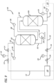
- Figures 8 and 9 show another embodiment of an ozonated water delivery system.
- the ozonated water delivery system 100 includes a first contacting device 102a and at least a second contacting device 102b.
- the first contacting device 102a, second contacting device 102b, or both comprise a packed column architecture.
- at least one of the first contacting device 102a and/or second contacting device 102b need not comprise a packed column architecture.
- at least one the first contacting device 102a and/or second contacting device 102b may comprise a membrane-based device or at least one membrane module.
- the first contacting device 102a may be in fluid communication with at least one ultrapure water source 104 (hereinafter UPW 104) via at least one ultrapure water conduit 106 (hereinafter UPW conduit 106).
- UPW 104 ultrapure water source 104
- UPW conduit 106 ultrapure water conduit 106
- At least one gas source 130 may be in communication with at least one of the UPW source 104, the UPW conduit 106, and/or the contacting device 102a via at least one gas conduit 112.
- the gas source 130 is coupled at least one gas conduit 112 which is coupled to the UPW conduit 106 via at least one coupling member 118.
- the ultrapure water flowing through the UPW conduit 106 reacts with the gas within the gas conduit 112 to form at least one reacting solution.
- the gas conduit 112 may include one or more controllers, valve devices, mass flow controllers, sensors, indicators, and the like thereon or in communication therewith.
- the gas conduit 112 includes two (2) valves 114 and one (1) indicator 116 thereon configured to prevent the backflow of water and/or gas into the gas source 130; although those skilled in the art will appreciate that any number of valves, indicators, controllers, and the like may be included on or in communication with the gas conduit 112 for any variety of applications.
- the gas source 130 may be configured to deliver carbon dioxide (CO2) to the ultrapure water flowing within the ultrapure conduit 106 to form an aqueous carbon dioxide solution prior to the ultrapure water entering the first contacting device 102a via at least one solution conduit 120.
- CO2 carbon dioxide
- the gas source 130 and gas conduit 112 may be configured to provide a flow of carbon dioxide to the ultrapure water flowing within the UPW conduit 106 at any desired flow rate.
- the gas source 130 and gas conduit 112 may be configured to provide a flow of carbon dioxide to the ultrapure water flowing within the UPW conduit 106 at a constant flow rate, independent of the flow rate of ultrapure water.
- the gas source 130 may in communication with the second contacting device 102b via at least one mixed gas conduit 132.
- the gas source 130 may be coupled to, in communication with, or include therein at least one ozone generator.
- a single gas source 130 is in fluid communication with the second contacting device 102b, although any number of gas sources 130 may be used.
- the gas source 130 shown in Figures 7 and 8 may be configured to provide a mixed gas consisting of oxygen (O2), ozone (O3), and carbon dioxide (CO2) to the contacting device 32.
- multiple gas sources 130 may be coupled to or otherwise in fluid communication with the second contacting device 102b.
- individual sources of oxygen (O2), ozone (O3), and carbon dioxide (CO2) may each be coupled to the mixed gas conduit 132 such that the mixed gas conduit 132 mixes and transports the mixed gas from the individual sources to the second contacting device 102b.
- at least one valve, mass flow controller, indicator, sensor, and the like may be positioned on or in communication with the mixed gas conduit 132.
- two (2) valves 134 and one (1) indicator 136 are included on the embodiment of the ozonated water delivery system 100 shown in Figures 7 and 8 configured to prevent the backflow of water and/or gas into the gas source 130, although those skilled in the art will appreciate that any number or valves, mass flow controllers, indicators, sensors, and the like may be coupled to or in communication with the mixed gas conduit 132.
- the aqueous carbon dioxide solution is introduced into the first contacting device 102a via the solution conduit 120.
- the mixed gas from the mixed gas conduit 132 is introduced into the second contacting device 102b.
- Some mixed gas is directed from the second contacting device 102b to the first contacting device 102a via at least one off gas coupling conduit 164 which is in fluid communication with the first contacting device 102a and the second contacting device 102b.
- the mixed gas from the second contacting device 102b may be introduced into the first contacting device 102a and reacts with the aqueous carbon dioxide within the first contacting device 102a thereby dissolving the ozone within the mixed gas in the aqueous carbon dioxide solution to provide a dissolved ozone/UPW solution.
- the dissolved ozone/UPW solution within the first contacting device 102a may be removed from the first contacting device 102a via at least one first contacting device conduit 152 and flowed into the second contacting device 102b, while off gas 166 is removed from the first contacting device 102a via at least one first contacting device off gas conduit 168.
- at least one pump 150 may be used to direct the dissolved ozone/UPW solution from the first contacting device 102a to the second contacting device 102b via the first contacting device conduit 152.
- the dissolved ozone/UPW solution from the first contacting device 102a is directed into the second contacting device 102b in the presence of the mixed gas from the gas source 130.
- the ozone the mixed gas within the second contacting device 102b dissolves in the dissolved ozone/UPW solution thereby resulting in higher concentration of dissolved ozone 160 which may be outputted from the second contacting device 102b via at least one second contacting device output conduit 162.
- Figures 7 and 8 show the first and second contacting devices coupled in series, the first and second contacting devices may be coupled in any desired configuration.
- Figure 9 shows an alternate embodiment of the ozonated water delivery system 100 shown in Figure 8 having at least one processor therein.
- at least one sensor, indicator, valve or the like may be positioned on the second contacting device output conduit 162.
- a sensor 170 is coupled to the second contacting device output conduit 162 although those skilled in the art any variety of other components, such as pressure sensors or level sensors, may similarly be included.
- the sensor 170 may be in communication with at least one processor 174 via at least one processor conduit 172.
- the processor 174 may be in communication with at least one of the UPW source 104, mass flow controller 114, indicator 116, gas source 130, mass flow controller 134, pump 150, and indicator 136 via the processor conduit 172. As such, the processor 174 may be configured to receive data from and provide data to at least one of the UPW source 104, mass flow controller 114, indicator 116, gas source 130, mass flow controller 134, indicator 136, and sensor 170. During use, the processor 174 may be configured to monitor the dissolved ozone concentration, and similar characteristics of the ozonated water and selectively vary the performance of the UPW source 104, mass flow controller 114, indicator 116, gas source 130, mass flow controller 134, pump 150, and sensor 170 accordingly.
- the pump 150 may be controlled to set the pressure of contacting device 102b 0.1 bar to 1 bar higher than the contacting device 102a, such as 0.2 bar to 0.7 bar higher, although those skilled in the art will appreciate that the contacting device 102b may operate at any desire pressure. As such, although not shown in Figure 9 , those skilled in the art will appreciate that the pump 150 may be in communication with the processor 174.
- the pressure in the second contacting device 102b will be controlled by the processor 174 to an effectively constant value.
- the pressure of the second contacting device 102b can be configured to be between 1 bar and 4 bar, such as between 1.8 bar and 2.5 bar.
Landscapes
- Chemical & Material Sciences (AREA)
- Chemical Kinetics & Catalysis (AREA)
- Life Sciences & Earth Sciences (AREA)
- Health & Medical Sciences (AREA)
- Engineering & Computer Science (AREA)
- Environmental & Geological Engineering (AREA)
- Water Supply & Treatment (AREA)
- Organic Chemistry (AREA)
- Hydrology & Water Resources (AREA)
- Medicinal Chemistry (AREA)
- Epidemiology (AREA)
- General Chemical & Material Sciences (AREA)
- Animal Behavior & Ethology (AREA)
- General Health & Medical Sciences (AREA)
- Public Health (AREA)
- Veterinary Medicine (AREA)
- Treatment Of Water By Oxidation Or Reduction (AREA)
- Oxygen, Ozone, And Oxides In General (AREA)
Applications Claiming Priority (2)
| Application Number | Priority Date | Filing Date | Title |
|---|---|---|---|
| US201862724368P | 2018-08-29 | 2018-08-29 | |
| PCT/US2019/048411 WO2020046994A1 (en) | 2018-08-29 | 2019-08-27 | Ozonated water delivery system and method of use |
Publications (3)
| Publication Number | Publication Date |
|---|---|
| EP3814284A1 EP3814284A1 (en) | 2021-05-05 |
| EP3814284A4 EP3814284A4 (en) | 2022-03-23 |
| EP3814284B1 true EP3814284B1 (en) | 2025-06-04 |
Family
ID=69639551
Family Applications (1)
| Application Number | Title | Priority Date | Filing Date |
|---|---|---|---|
| EP19856235.7A Active EP3814284B1 (en) | 2018-08-29 | 2019-08-27 | Ozonated water delivery system and method of use |
Country Status (9)
| Country | Link |
|---|---|
| US (1) | US11518696B2 (https=) |
| EP (1) | EP3814284B1 (https=) |
| JP (1) | JP7422135B2 (https=) |
| KR (2) | KR20210038980A (https=) |
| CN (2) | CN119735291A (https=) |
| IL (1) | IL281134A (https=) |
| SG (1) | SG11202100619PA (https=) |
| TW (1) | TWI912238B (https=) |
| WO (1) | WO2020046994A1 (https=) |
Families Citing this family (2)
| Publication number | Priority date | Publication date | Assignee | Title |
|---|---|---|---|---|
| WO2024020126A1 (en) * | 2022-07-20 | 2024-01-25 | Evoqua Water Technologies Llc | Mobile ultrapure water system |
| JP2024035532A (ja) * | 2022-09-02 | 2024-03-14 | 株式会社荏原製作所 | ガス溶解液供給装置 |
Family Cites Families (43)
| Publication number | Priority date | Publication date | Assignee | Title |
|---|---|---|---|---|
| US5261966A (en) | 1991-01-28 | 1993-11-16 | Kabushiki Kaisha Toshiba | Method of cleaning semiconductor wafers using mixer containing a bundle of gas permeable hollow yarns |
| EP0598424A3 (en) | 1992-11-16 | 1996-05-15 | Novellus Systems Inc | Device for removing dissolved gas from a liquid. |
| JP3174856B2 (ja) | 1993-05-07 | 2001-06-11 | 日本エア・リキード株式会社 | 混合ガス供給装置 |
| US6001223A (en) | 1995-07-07 | 1999-12-14 | Air Liquide America Corporation | On-site ammonia purification for semiconductor manufacture |
| EP0913233B1 (en) | 1997-10-31 | 2005-05-11 | Ebara Corporation | Polishing solution supply system |
| US20070119816A1 (en) | 1998-04-16 | 2007-05-31 | Urquhart Karl J | Systems and methods for reclaiming process fluids in a processing environment |
| US7980753B2 (en) | 1998-04-16 | 2011-07-19 | Air Liquide Electronics U.S. Lp | Systems and methods for managing fluids in a processing environment using a liquid ring pump and reclamation system |
| JP2000037695A (ja) * | 1998-07-24 | 2000-02-08 | Kurita Water Ind Ltd | オゾン水供給装置 |
| US6247838B1 (en) | 1998-11-24 | 2001-06-19 | The Boc Group, Inc. | Method for producing a liquid mixture having a predetermined concentration of a specified component |
| JP2000262874A (ja) * | 1999-03-15 | 2000-09-26 | Mitsubishi Electric Corp | オゾン水の製造方法および製造装置 |
| JP3748731B2 (ja) | 1999-03-26 | 2006-02-22 | 株式会社荏原製作所 | 砥液供給装置 |
| JP2003512736A (ja) | 1999-10-19 | 2003-04-02 | フィファー・スミス・コーポレーション | オゾン−溶媒溶液を用いた基体の処理方法及び処理装置 |
| JP2001129376A (ja) * | 1999-11-08 | 2001-05-15 | Ishikawajima Harima Heavy Ind Co Ltd | オゾン水製造方法及び製造装置 |
| EP1305107B1 (en) | 2000-07-31 | 2006-09-20 | Kinetics Chempure Systems, Inc. | Method and apparatus for blending process materials |
| US6805791B2 (en) | 2000-09-01 | 2004-10-19 | Applied Science And Technology, Inc. | Ozonated water flow and concentration control apparatus |
| US6884359B2 (en) * | 2000-09-27 | 2005-04-26 | Dainippon Ink And Chemicals, Inc. | Apparatus and method for controlling resistivity of ultra pure water |
| US6766818B2 (en) | 2001-04-06 | 2004-07-27 | Akrion, Llc | Chemical concentration control device |
| CN1602538A (zh) | 2001-11-13 | 2005-03-30 | Fsi国际公司 | 用于浸渍处理的高级处理控制 |
| US6732017B2 (en) | 2002-02-15 | 2004-05-04 | Lam Research Corp. | System and method for point of use delivery, control and mixing chemical and slurry for CMP/cleaning system |
| JP2003334433A (ja) | 2002-05-16 | 2003-11-25 | Kurita Water Ind Ltd | 連続溶解装置、連続溶解方法及び気体溶解水供給装置 |
| EP1367149B1 (en) | 2002-05-29 | 2011-11-16 | Toyo Tanso Co., Ltd. | Fluorine gas generator |
| KR20100105906A (ko) | 2002-07-19 | 2010-09-30 | 엔테그리스, 아이엔씨. | 유체유동측정 및 비례유체유동 제어장치 |
| CN1332741C (zh) | 2002-07-19 | 2007-08-22 | 动力系统有限公司 | 混合过程原料的方法和设备 |
| CN100374768C (zh) | 2002-07-19 | 2008-03-12 | 诚实公司 | 液体流动控制设备及方法 |
| JP3527735B1 (ja) | 2002-11-20 | 2004-05-17 | 東洋炭素株式会社 | フッ素ガス発生装置 |
| US7976718B2 (en) | 2003-12-30 | 2011-07-12 | Akrion Systems Llc | System and method for selective etching of silicon nitride during substrate processing |
| US7107128B2 (en) | 2004-02-13 | 2006-09-12 | Entegris, Inc. | System for controlling fluid flow |
| US20060080041A1 (en) | 2004-07-08 | 2006-04-13 | Anderson Gary R | Chemical mixing apparatus, system and method |
| US20060021634A1 (en) | 2004-07-08 | 2006-02-02 | Liu Zhi Lewis | Method and apparatus for creating ozonated process solutions having high ozone concentration |
| JP3777451B2 (ja) | 2004-08-18 | 2006-05-24 | 株式会社プレテック | オゾン水生成方法及びオゾン水製造装置 |
| TWI552797B (zh) | 2005-06-22 | 2016-10-11 | 恩特葛瑞斯股份有限公司 | 整合式氣體混合用之裝置及方法 |
| TWI402423B (zh) | 2006-02-28 | 2013-07-21 | Entegris Inc | 用於一幫浦操作之系統及方法 |
| US7743783B2 (en) | 2006-04-04 | 2010-06-29 | Air Liquide Electronics U.S. Lp | Method and apparatus for recycling process fluids |
| JP4830731B2 (ja) | 2006-09-06 | 2011-12-07 | 栗田工業株式会社 | ガス溶解水供給装置 |
| US8448925B2 (en) * | 2006-10-17 | 2013-05-28 | Mks Instruments, Inc. | Devices, systems, and methods for carbonation of deionized water |
| EP2104648B1 (en) * | 2006-10-17 | 2013-04-17 | MKS Instruments, Inc. | System and method for carbonation of deionized water |
| JP5466817B2 (ja) | 2007-09-03 | 2014-04-09 | シャープ株式会社 | オゾン水製造装置 |
| JP5020784B2 (ja) | 2007-11-08 | 2012-09-05 | 野村マイクロ・サイエンス株式会社 | オゾン水の製造装置及び製造方法 |
| JP5412135B2 (ja) | 2009-02-23 | 2014-02-12 | 野村マイクロ・サイエンス株式会社 | オゾン水供給装置 |
| US8747762B2 (en) | 2009-12-03 | 2014-06-10 | Applied Materials, Inc. | Methods and apparatus for treating exhaust gas in a processing system |
| JP5779321B2 (ja) * | 2010-06-18 | 2015-09-16 | シャープ株式会社 | 高濃度オゾン水の製造方法及び高濃度オゾン水の製造装置 |
| US9056262B2 (en) * | 2012-11-08 | 2015-06-16 | Mks Instruments, Inc. | Pressure-less ozonated Di-water (DIO3) recirculation reclaim system |
| US10773221B2 (en) | 2016-11-11 | 2020-09-15 | Mks Instruments, Inc. | Systems and methods for generating a conductive liquid comprising deionized water with ammonia gas dissolved therein |
-
2019
- 2019-08-27 CN CN202510101507.4A patent/CN119735291A/zh active Pending
- 2019-08-27 SG SG11202100619PA patent/SG11202100619PA/en unknown
- 2019-08-27 EP EP19856235.7A patent/EP3814284B1/en active Active
- 2019-08-27 US US16/553,033 patent/US11518696B2/en active Active
- 2019-08-27 JP JP2021510328A patent/JP7422135B2/ja active Active
- 2019-08-27 KR KR1020217008472A patent/KR20210038980A/ko not_active Ceased
- 2019-08-27 KR KR1020237040837A patent/KR102692467B1/ko active Active
- 2019-08-27 WO PCT/US2019/048411 patent/WO2020046994A1/en not_active Ceased
- 2019-08-27 CN CN201980054540.9A patent/CN112601720A/zh active Pending
- 2019-08-29 TW TW108130968A patent/TWI912238B/zh active
-
2021
- 2021-02-26 IL IL281134A patent/IL281134A/en unknown
Also Published As
| Publication number | Publication date |
|---|---|
| IL281134A (en) | 2021-04-29 |
| WO2020046994A1 (en) | 2020-03-05 |
| KR102692467B1 (ko) | 2024-08-07 |
| CN119735291A (zh) | 2025-04-01 |
| EP3814284A4 (en) | 2022-03-23 |
| JP2022502235A (ja) | 2022-01-11 |
| US20200071208A1 (en) | 2020-03-05 |
| EP3814284A1 (en) | 2021-05-05 |
| CN112601720A (zh) | 2021-04-02 |
| TWI912238B (zh) | 2026-01-21 |
| KR20230165878A (ko) | 2023-12-05 |
| KR20210038980A (ko) | 2021-04-08 |
| SG11202100619PA (en) | 2021-02-25 |
| US11518696B2 (en) | 2022-12-06 |
| TW202023962A (zh) | 2020-07-01 |
| JP7422135B2 (ja) | 2024-01-25 |
Similar Documents
| Publication | Publication Date | Title |
|---|---|---|
| CN100549894C (zh) | 控制臭氧化水流量及浓度的设备和方法 | |
| CN102986008B (zh) | 用于去离子水的碳酸化的装置、系统及方法 | |
| EP2104648B1 (en) | System and method for carbonation of deionized water | |
| EP3814284B1 (en) | Ozonated water delivery system and method of use | |
| CA2710069A1 (en) | Method for the treatment of water using chlorine dioxide | |
| US20020081237A1 (en) | On-site generation of ultra-high-purity buffered-HF and ammonium fluoride | |
| WO1996039651A1 (en) | System and method for on-site mixing of ultra-high-purity chemicals for semiconductor processing | |
| JP2022502235A5 (https=) | ||
| JPH1192104A (ja) | 高純度な二酸化塩素水性組成物、その製造方法及び製造装置 | |
| EP0836719A1 (en) | System and method for on-site mixing of ultra-high-purity chemicals for semiconductor processing |
Legal Events
| Date | Code | Title | Description |
|---|---|---|---|
| STAA | Information on the status of an ep patent application or granted ep patent |
Free format text: STATUS: THE INTERNATIONAL PUBLICATION HAS BEEN MADE |
|
| PUAI | Public reference made under article 153(3) epc to a published international application that has entered the european phase |
Free format text: ORIGINAL CODE: 0009012 |
|
| STAA | Information on the status of an ep patent application or granted ep patent |
Free format text: STATUS: REQUEST FOR EXAMINATION WAS MADE |
|
| 17P | Request for examination filed |
Effective date: 20210128 |
|
| AK | Designated contracting states |
Kind code of ref document: A1 Designated state(s): AL AT BE BG CH CY CZ DE DK EE ES FI FR GB GR HR HU IE IS IT LI LT LU LV MC MK MT NL NO PL PT RO RS SE SI SK SM TR |
|
| DAV | Request for validation of the european patent (deleted) | ||
| DAX | Request for extension of the european patent (deleted) | ||
| A4 | Supplementary search report drawn up and despatched |
Effective date: 20220221 |
|
| RIC1 | Information provided on ipc code assigned before grant |
Ipc: B01F 33/81 20220101ALI20220215BHEP Ipc: B01F 35/221 20220101ALI20220215BHEP Ipc: B01F 35/21 20220101ALI20220215BHEP Ipc: B01F 23/20 20220101ALI20220215BHEP Ipc: B01F 23/237 20220101ALI20220215BHEP Ipc: B01F 23/232 20220101ALI20220215BHEP Ipc: C02F 1/78 20060101AFI20220215BHEP |
|
| STAA | Information on the status of an ep patent application or granted ep patent |
Free format text: STATUS: EXAMINATION IS IN PROGRESS |
|
| 17Q | First examination report despatched |
Effective date: 20230405 |
|
| REG | Reference to a national code |
Ref country code: DE Ref legal event code: R079 Free format text: PREVIOUS MAIN CLASS: C02F0001780000 Ipc: B01F0033810000 Ref country code: DE Ref legal event code: R079 Ref document number: 602019070875 Country of ref document: DE Free format text: PREVIOUS MAIN CLASS: C02F0001780000 Ipc: B01F0033810000 |
|
| RIC1 | Information provided on ipc code assigned before grant |
Ipc: C02F 103/04 20060101ALI20250203BHEP Ipc: C02F 1/68 20060101ALI20250203BHEP Ipc: C02F 1/78 20060101ALI20250203BHEP Ipc: B01F 23/232 20220101ALI20250203BHEP Ipc: B01F 23/237 20220101ALI20250203BHEP Ipc: B01F 23/20 20220101ALI20250203BHEP Ipc: B01F 35/21 20220101ALI20250203BHEP Ipc: B01F 35/221 20220101ALI20250203BHEP Ipc: B01F 33/81 20220101AFI20250203BHEP |
|
| GRAP | Despatch of communication of intention to grant a patent |
Free format text: ORIGINAL CODE: EPIDOSNIGR1 |
|
| STAA | Information on the status of an ep patent application or granted ep patent |
Free format text: STATUS: GRANT OF PATENT IS INTENDED |
|
| INTG | Intention to grant announced |
Effective date: 20250314 |
|
| GRAS | Grant fee paid |
Free format text: ORIGINAL CODE: EPIDOSNIGR3 |
|
| GRAA | (expected) grant |
Free format text: ORIGINAL CODE: 0009210 |
|
| STAA | Information on the status of an ep patent application or granted ep patent |
Free format text: STATUS: THE PATENT HAS BEEN GRANTED |
|
| AK | Designated contracting states |
Kind code of ref document: B1 Designated state(s): AL AT BE BG CH CY CZ DE DK EE ES FI FR GB GR HR HU IE IS IT LI LT LU LV MC MK MT NL NO PL PT RO RS SE SI SK SM TR |
|
| REG | Reference to a national code |
Ref country code: GB Ref legal event code: FG4D |
|
| REG | Reference to a national code |
Ref country code: CH Ref legal event code: EP |
|
| REG | Reference to a national code |
Ref country code: DE Ref legal event code: R096 Ref document number: 602019070875 Country of ref document: DE |
|
| REG | Reference to a national code |
Ref country code: IE Ref legal event code: FG4D |
|
| REG | Reference to a national code |
Ref country code: NL Ref legal event code: MP Effective date: 20250604 |
|
| PG25 | Lapsed in a contracting state [announced via postgrant information from national office to epo] |
Ref country code: FI Free format text: LAPSE BECAUSE OF FAILURE TO SUBMIT A TRANSLATION OF THE DESCRIPTION OR TO PAY THE FEE WITHIN THE PRESCRIBED TIME-LIMIT Effective date: 20250604 Ref country code: ES Free format text: LAPSE BECAUSE OF FAILURE TO SUBMIT A TRANSLATION OF THE DESCRIPTION OR TO PAY THE FEE WITHIN THE PRESCRIBED TIME-LIMIT Effective date: 20250604 |
|
| PGFP | Annual fee paid to national office [announced via postgrant information from national office to epo] |
Ref country code: DE Payment date: 20250827 Year of fee payment: 7 |
|
| REG | Reference to a national code |
Ref country code: LT Ref legal event code: MG9D |
|
| PG25 | Lapsed in a contracting state [announced via postgrant information from national office to epo] |
Ref country code: NO Free format text: LAPSE BECAUSE OF FAILURE TO SUBMIT A TRANSLATION OF THE DESCRIPTION OR TO PAY THE FEE WITHIN THE PRESCRIBED TIME-LIMIT Effective date: 20250904 Ref country code: GR Free format text: LAPSE BECAUSE OF FAILURE TO SUBMIT A TRANSLATION OF THE DESCRIPTION OR TO PAY THE FEE WITHIN THE PRESCRIBED TIME-LIMIT Effective date: 20250905 |
|
| PG25 | Lapsed in a contracting state [announced via postgrant information from national office to epo] |
Ref country code: PL Free format text: LAPSE BECAUSE OF FAILURE TO SUBMIT A TRANSLATION OF THE DESCRIPTION OR TO PAY THE FEE WITHIN THE PRESCRIBED TIME-LIMIT Effective date: 20250604 |
|
| PG25 | Lapsed in a contracting state [announced via postgrant information from national office to epo] |
Ref country code: BG Free format text: LAPSE BECAUSE OF FAILURE TO SUBMIT A TRANSLATION OF THE DESCRIPTION OR TO PAY THE FEE WITHIN THE PRESCRIBED TIME-LIMIT Effective date: 20250604 |
|
| PG25 | Lapsed in a contracting state [announced via postgrant information from national office to epo] |
Ref country code: HR Free format text: LAPSE BECAUSE OF FAILURE TO SUBMIT A TRANSLATION OF THE DESCRIPTION OR TO PAY THE FEE WITHIN THE PRESCRIBED TIME-LIMIT Effective date: 20250604 |
|
| PG25 | Lapsed in a contracting state [announced via postgrant information from national office to epo] |
Ref country code: RS Free format text: LAPSE BECAUSE OF FAILURE TO SUBMIT A TRANSLATION OF THE DESCRIPTION OR TO PAY THE FEE WITHIN THE PRESCRIBED TIME-LIMIT Effective date: 20250904 |
|
| PG25 | Lapsed in a contracting state [announced via postgrant information from national office to epo] |
Ref country code: LV Free format text: LAPSE BECAUSE OF FAILURE TO SUBMIT A TRANSLATION OF THE DESCRIPTION OR TO PAY THE FEE WITHIN THE PRESCRIBED TIME-LIMIT Effective date: 20250604 |
|
| PG25 | Lapsed in a contracting state [announced via postgrant information from national office to epo] |
Ref country code: NL Free format text: LAPSE BECAUSE OF FAILURE TO SUBMIT A TRANSLATION OF THE DESCRIPTION OR TO PAY THE FEE WITHIN THE PRESCRIBED TIME-LIMIT Effective date: 20250604 |
|
| PG25 | Lapsed in a contracting state [announced via postgrant information from national office to epo] |
Ref country code: PT Free format text: LAPSE BECAUSE OF FAILURE TO SUBMIT A TRANSLATION OF THE DESCRIPTION OR TO PAY THE FEE WITHIN THE PRESCRIBED TIME-LIMIT Effective date: 20251006 |
|
| REG | Reference to a national code |
Ref country code: AT Ref legal event code: MK05 Ref document number: 1799858 Country of ref document: AT Kind code of ref document: T Effective date: 20250604 |
|
| PG25 | Lapsed in a contracting state [announced via postgrant information from national office to epo] |
Ref country code: IS Free format text: LAPSE BECAUSE OF FAILURE TO SUBMIT A TRANSLATION OF THE DESCRIPTION OR TO PAY THE FEE WITHIN THE PRESCRIBED TIME-LIMIT Effective date: 20251004 |
|
| PG25 | Lapsed in a contracting state [announced via postgrant information from national office to epo] |
Ref country code: SM Free format text: LAPSE BECAUSE OF FAILURE TO SUBMIT A TRANSLATION OF THE DESCRIPTION OR TO PAY THE FEE WITHIN THE PRESCRIBED TIME-LIMIT Effective date: 20250604 Ref country code: AT Free format text: LAPSE BECAUSE OF FAILURE TO SUBMIT A TRANSLATION OF THE DESCRIPTION OR TO PAY THE FEE WITHIN THE PRESCRIBED TIME-LIMIT Effective date: 20250604 |
|
| PG25 | Lapsed in a contracting state [announced via postgrant information from national office to epo] |
Ref country code: CZ Free format text: LAPSE BECAUSE OF FAILURE TO SUBMIT A TRANSLATION OF THE DESCRIPTION OR TO PAY THE FEE WITHIN THE PRESCRIBED TIME-LIMIT Effective date: 20250604 |
|
| PG25 | Lapsed in a contracting state [announced via postgrant information from national office to epo] |
Ref country code: EE Free format text: LAPSE BECAUSE OF FAILURE TO SUBMIT A TRANSLATION OF THE DESCRIPTION OR TO PAY THE FEE WITHIN THE PRESCRIBED TIME-LIMIT Effective date: 20250604 |
|
| PG25 | Lapsed in a contracting state [announced via postgrant information from national office to epo] |
Ref country code: SK Free format text: LAPSE BECAUSE OF FAILURE TO SUBMIT A TRANSLATION OF THE DESCRIPTION OR TO PAY THE FEE WITHIN THE PRESCRIBED TIME-LIMIT Effective date: 20250604 Ref country code: RO Free format text: LAPSE BECAUSE OF FAILURE TO SUBMIT A TRANSLATION OF THE DESCRIPTION OR TO PAY THE FEE WITHIN THE PRESCRIBED TIME-LIMIT Effective date: 20250604 |
|
| PG25 | Lapsed in a contracting state [announced via postgrant information from national office to epo] |
Ref country code: IT Free format text: LAPSE BECAUSE OF FAILURE TO SUBMIT A TRANSLATION OF THE DESCRIPTION OR TO PAY THE FEE WITHIN THE PRESCRIBED TIME-LIMIT Effective date: 20250604 |
|
| REG | Reference to a national code |
Ref country code: DE Ref legal event code: R097 Ref document number: 602019070875 Country of ref document: DE |
|
| REG | Reference to a national code |
Ref country code: CH Ref legal event code: H13 Free format text: ST27 STATUS EVENT CODE: U-0-0-H10-H13 (AS PROVIDED BY THE NATIONAL OFFICE) Effective date: 20260324 |
|
| PG25 | Lapsed in a contracting state [announced via postgrant information from national office to epo] |
Ref country code: MC Free format text: LAPSE BECAUSE OF FAILURE TO SUBMIT A TRANSLATION OF THE DESCRIPTION OR TO PAY THE FEE WITHIN THE PRESCRIBED TIME-LIMIT Effective date: 20250604 |
|
| PLBE | No opposition filed within time limit |
Free format text: ORIGINAL CODE: 0009261 |
|
| STAA | Information on the status of an ep patent application or granted ep patent |
Free format text: STATUS: NO OPPOSITION FILED WITHIN TIME LIMIT |
|
| PG25 | Lapsed in a contracting state [announced via postgrant information from national office to epo] |
Ref country code: DK Free format text: LAPSE BECAUSE OF FAILURE TO SUBMIT A TRANSLATION OF THE DESCRIPTION OR TO PAY THE FEE WITHIN THE PRESCRIBED TIME-LIMIT Effective date: 20250604 |
|
| PG25 | Lapsed in a contracting state [announced via postgrant information from national office to epo] |
Ref country code: LU Free format text: LAPSE BECAUSE OF NON-PAYMENT OF DUE FEES Effective date: 20250827 |
|
| REG | Reference to a national code |
Ref country code: CH Ref legal event code: L10 Free format text: ST27 STATUS EVENT CODE: U-0-0-L10-L00 (AS PROVIDED BY THE NATIONAL OFFICE) Effective date: 20260416 |
|
| PG25 | Lapsed in a contracting state [announced via postgrant information from national office to epo] |
Ref country code: CH Free format text: LAPSE BECAUSE OF NON-PAYMENT OF DUE FEES Effective date: 20250831 |