EP1305107B1 - Method and apparatus for blending process materials - Google Patents
Method and apparatus for blending process materials Download PDFInfo
- Publication number
- EP1305107B1 EP1305107B1 EP01959858A EP01959858A EP1305107B1 EP 1305107 B1 EP1305107 B1 EP 1305107B1 EP 01959858 A EP01959858 A EP 01959858A EP 01959858 A EP01959858 A EP 01959858A EP 1305107 B1 EP1305107 B1 EP 1305107B1
- Authority
- EP
- European Patent Office
- Prior art keywords
- sensor
- material supply
- process materials
- controller
- supply lines
- Prior art date
- Legal status (The legal status is an assumption and is not a legal conclusion. Google has not performed a legal analysis and makes no representation as to the accuracy of the status listed.)
- Expired - Lifetime
Links
Images


Classifications
-
- G—PHYSICS
- G05—CONTROLLING; REGULATING
- G05D—SYSTEMS FOR CONTROLLING OR REGULATING NON-ELECTRIC VARIABLES
- G05D11/00—Control of flow ratio
- G05D11/02—Controlling ratio of two or more flows of fluid or fluent material
- G05D11/13—Controlling ratio of two or more flows of fluid or fluent material characterised by the use of electric means
- G05D11/135—Controlling ratio of two or more flows of fluid or fluent material characterised by the use of electric means by sensing at least one property of the mixture
-
- B—PERFORMING OPERATIONS; TRANSPORTING
- B01—PHYSICAL OR CHEMICAL PROCESSES OR APPARATUS IN GENERAL
- B01F—MIXING, e.g. DISSOLVING, EMULSIFYING OR DISPERSING
- B01F35/00—Accessories for mixers; Auxiliary operations or auxiliary devices; Parts or details of general application
- B01F35/80—Forming a predetermined ratio of the substances to be mixed
-
- B—PERFORMING OPERATIONS; TRANSPORTING
- B01—PHYSICAL OR CHEMICAL PROCESSES OR APPARATUS IN GENERAL
- B01F—MIXING, e.g. DISSOLVING, EMULSIFYING OR DISPERSING
- B01F25/00—Flow mixers; Mixers for falling materials, e.g. solid particles
- B01F25/30—Injector mixers
- B01F25/31—Injector mixers in conduits or tubes through which the main component flows
- B01F25/313—Injector mixers in conduits or tubes through which the main component flows wherein additional components are introduced in the centre of the conduit
- B01F25/3131—Injector mixers in conduits or tubes through which the main component flows wherein additional components are introduced in the centre of the conduit with additional mixing means other than injector mixers, e.g. screens, baffles or rotating elements
-
- B—PERFORMING OPERATIONS; TRANSPORTING
- B01—PHYSICAL OR CHEMICAL PROCESSES OR APPARATUS IN GENERAL
- B01F—MIXING, e.g. DISSOLVING, EMULSIFYING OR DISPERSING
- B01F25/00—Flow mixers; Mixers for falling materials, e.g. solid particles
- B01F25/40—Static mixers
- B01F25/42—Static mixers in which the mixing is affected by moving the components jointly in changing directions, e.g. in tubes provided with baffles or obstructions
- B01F25/43—Mixing tubes, e.g. wherein the material is moved in a radial or partly reversed direction
- B01F25/433—Mixing tubes wherein the shape of the tube influences the mixing, e.g. mixing tubes with varying cross-section or provided with inwardly extending profiles
- B01F25/4335—Mixers with a converging-diverging cross-section
-
- B—PERFORMING OPERATIONS; TRANSPORTING
- B01—PHYSICAL OR CHEMICAL PROCESSES OR APPARATUS IN GENERAL
- B01F—MIXING, e.g. DISSOLVING, EMULSIFYING OR DISPERSING
- B01F35/00—Accessories for mixers; Auxiliary operations or auxiliary devices; Parts or details of general application
- B01F35/20—Measuring; Control or regulation
- B01F35/21—Measuring
- B01F35/2132—Concentration, pH, pOH, p(ION) or oxygen-demand
-
- B—PERFORMING OPERATIONS; TRANSPORTING
- B01—PHYSICAL OR CHEMICAL PROCESSES OR APPARATUS IN GENERAL
- B01F—MIXING, e.g. DISSOLVING, EMULSIFYING OR DISPERSING
- B01F35/00—Accessories for mixers; Auxiliary operations or auxiliary devices; Parts or details of general application
- B01F35/20—Measuring; Control or regulation
- B01F35/21—Measuring
- B01F35/2134—Density or solids or particle number
-
- B—PERFORMING OPERATIONS; TRANSPORTING
- B01—PHYSICAL OR CHEMICAL PROCESSES OR APPARATUS IN GENERAL
- B01F—MIXING, e.g. DISSOLVING, EMULSIFYING OR DISPERSING
- B01F35/00—Accessories for mixers; Auxiliary operations or auxiliary devices; Parts or details of general application
- B01F35/80—Forming a predetermined ratio of the substances to be mixed
- B01F35/82—Forming a predetermined ratio of the substances to be mixed by adding a material to be mixed to a mixture in response to a detected feature, e.g. density, radioactivity, consumed power or colour
-
- B—PERFORMING OPERATIONS; TRANSPORTING
- B01—PHYSICAL OR CHEMICAL PROCESSES OR APPARATUS IN GENERAL
- B01F—MIXING, e.g. DISSOLVING, EMULSIFYING OR DISPERSING
- B01F35/00—Accessories for mixers; Auxiliary operations or auxiliary devices; Parts or details of general application
- B01F35/80—Forming a predetermined ratio of the substances to be mixed
- B01F35/88—Forming a predetermined ratio of the substances to be mixed by feeding the materials batchwise
- B01F35/883—Forming a predetermined ratio of the substances to be mixed by feeding the materials batchwise using flow rate controls for feeding the substances
-
- B—PERFORMING OPERATIONS; TRANSPORTING
- B01—PHYSICAL OR CHEMICAL PROCESSES OR APPARATUS IN GENERAL
- B01F—MIXING, e.g. DISSOLVING, EMULSIFYING OR DISPERSING
- B01F2101/00—Mixing characterised by the nature of the mixed materials or by the application field
- B01F2101/27—Mixing ingredients for grinding, polishing or lapping materials
-
- B—PERFORMING OPERATIONS; TRANSPORTING
- B01—PHYSICAL OR CHEMICAL PROCESSES OR APPARATUS IN GENERAL
- B01F—MIXING, e.g. DISSOLVING, EMULSIFYING OR DISPERSING
- B01F2101/00—Mixing characterised by the nature of the mixed materials or by the application field
- B01F2101/58—Mixing semiconducting materials, e.g. during semiconductor or wafer manufacturing processes
-
- B—PERFORMING OPERATIONS; TRANSPORTING
- B01—PHYSICAL OR CHEMICAL PROCESSES OR APPARATUS IN GENERAL
- B01F—MIXING, e.g. DISSOLVING, EMULSIFYING OR DISPERSING
- B01F23/00—Mixing according to the phases to be mixed, e.g. dispersing or emulsifying
- B01F23/40—Mixing liquids with liquids; Emulsifying
Definitions
- the present invention is directed to a method and apparatus for blending process materials and, particularly, to a method and apparatus for blending ultra-high purity chemicals, abrasive slurries and the like.
- Blended process materials are required, for example, in the pharmaceutical, cosmetic and semiconductor industries.
- blended process materials are typically prepared using batch production systems including a dispensing subsystem and a mixing subsystem.
- the dispensing subsystem transfers materials from a supply source to the mixing subsystem.
- Supply sources are typically containers designed for safe storage of a process material, such as a chemical or slurry.
- Other supply sources include facility generation plants, such as deionized (DI) water generation facilities or facilities for supplying other mass-consumed process materials, such as hydrogen peroxide or ammonium hydroxide.
- DI deionized
- the facility generation plant may be directly connected to the dispensing subsystem.
- a single dispensing subsystem may connect to a variety of supply sources, transferring process material from each to the mixing subsystem.
- the process materials transferred by the dispensing subsystem are added to a mixing vessel or tank.
- the materials are added in a predetermined sequence, as required for a particular process.
- the process may require a predetermined ratio of individual process materials to create a desired blend.
- the sequence of the process may be based on reactivity or safety, for example an acidic or basic solution is typically added after water.
- the sequence of the process may be based on the need to reduce or correct process variances, such as dilution of an excessively concentrated wafer polish slurry with DI water.
- Typical mass difference regulated additions may involve the use of a scale on a holding vessel or tank. In this type of system, each process material is added individually, as an automated control system measuring the mass of the holding vessel is not able to discern the relative amounts of two process materials added simultaneously.
- Typical volume difference regulated additions may involve the use of flow meters.
- the process materials are typically blended into a homogeneous solution with an impeller, forming a batch of blended process materials.
- the batch of blended process materials is typically then used for its intended application.
- DE 23 20 212 discloses a blending system and a method of blending materials.
- US-A-5 332 125 discloses a method and apparatus for metering flow of a two-component dispensing system.
- US-A-5 271 521 discloses a method and apparatus for compensating for changes in viscosity in a two-component dispensing system.
- the present invention is directed to a blending system, according to claim 1.
- the blending system further comprises a process control system including a first flow control device positioned on at least one of the first and the second material supply lines, a first sensor positioned downstream of the static mixer, and a controller comprising logic code to provide a control signal to the first flow control device based upon a sensor signal provided by the first sensor.
- the present invention is directed to a blending system according to claim 11.
- the blending system also includes a process control system including a controller, an input device in communication with the controller to provide an input signal representing a desired blend of process materials, and a first valve connected to one of the plurality of material supply lines and to the controller.
- the blending system further includes a dispensing subsystem including a holding vessel having an inlet and an outlet, a recirculation line fluidly connected to the inlet and the outlet and a second valve fluidly connected to the recirculation line and to one of the plurality of material supply lines such that material from the recirculation line may be selectively diverted to the material supply line.
- the present invention is directed to a method of supplying blended process materials according to claim 20.
- the method includes supplying a first process material through a first of material supply line, supplying a second process material through a second of material supply line, and blending the first and the second process materials in a static mixer fluidly connected downstream of the first and the second material supply lines.
- the method also includes regulating the supply of one of the first and the second process materials with a first valve positioned on one of the first and the second material supply lines based upon a sensor signal provided by a sensor positioned downstream of the static mixer.
- the present invention is directed to a method of supplying blended process materials according to claim 23.
- the method includes supplying a plurality of process materials through a plurality of material supply lines and blending the plurality of process materials in a static mixer positioned downstream of the plurality of material supply lines.
- the method also includes regulating the supply of the plurality of process materials with a process control system including a controller, an input device, and a first valve connected to one of the plurality of material supply lines and to the controller.
- the input device is connected to the controller to provide an input signal representing a desired blend of process materials.
- the method further includes holding one or more of the plurality of process materials in a holding vessel having an inlet and an outlet, recirculating the one or more of the plurality of process materials in a recirculation line connected to the holding vessel inlet and outlet, and diverting a portion of the one or more of the plurality of process materials into one of the plurality of material supply lines with a second valve connected to the recirculation line and to the one or more of the plurality of material supply lines.
- the present invention is directed to a system for blending process materials.
- the blending system is suitable for blending and supplying process materials on demand to a point of use or for providing a blend of process materials for later use.
- process materials it is meant any fluid material capable of being transported through a conduit.
- process materials may include water, various chemicals, solutions, suspensions of solids, slurries or any such other materials.
- the blending system of the present invention is for use with any process requiring blended process materials, it is particularly applicable to the blending of ultra high purity chemicals and abrasive slurries and other blending applications were accuracy and precision are desired.
- the present invention is particularly useful in the semiconductor, cosmetic and pharmaceutical industries.
- An embodiment of the blending system of the invention includes a plurality of material supply lines, a static mixer positioned downstream of the plurality of material supply lines and a process control system.
- the plurality of material supply lines may be any conduits for carrying process materials.
- material supply lines may be pipes, channels or other devices for directing fluid flow.
- the plurality of material supply lines may supply many different process materials from a variety of sources.
- material supply lines may supply process materials from storage containers or from facility generation plants.
- the material supply lines may supply process materials from a dispensing subsystem.
- the dispensing subsystem may consist of a holding vessel, a recirculation line and a valve.
- the recirculation line may be fluidly connected to the inlet and the outlet of the holding vessel to provide continuous circulation of process material through the recirculation line. This flow may be provided by a device for inducing fluid flow, such as a pump.
- the valve in the dispensing subsystem may be connected to the recirculation line and to a material supply line, such that process material may be diverted from the recirculation line to the material supply line.
- the static mixer of the blending system of the present invention is in fluid communication with the plurality of material supply lines.
- the static mixer includes a plurality of inlets, each connected to one of the plurality of material supply lines.
- the static mixer also includes a mixing region and an outlet. Process materials are received from the material supply lines at the inlets of the static mixer and passed to the mixing region.
- the mixing region is shaped to cause agitation and mixing of the process materials flowing through it. After mixing, the process materials pass through the outlet, which is connected to a point of use or storage vessel. Points of use are any location where there is demand for a supply of blended process materials. For example, points of use may include process machinery or work stations.
- the process control system of the blending system of the invention may include a controller, an input device and a valve. In other embodiments, the process control system may include a controller, a sensor and a valve. It should be appreciated that valves are discussed herein for controlling flow by way of example only; any flow control device may be substituted for any valve in the invention. By flow control device, it is meant any device that is able to provide a desired level of flow control, such as various types of valves, pumps and other pressure modifying devices.
- the controller may be any device capable of receiving information and acting upon the information based upon a series of protocols, such as logic code.
- the controller may be a microprocessor based device, such as a computer.
- the input device may be connected to the controller to provide an input signal representing a desired blend of process materials.
- the input device may be any device capable of receiving information and relaying it to the controller.
- the input device may be a potentiometer, key pad or Supervision Control And Data Acquisition (SCADA) node.
- SCADA Supervision Control And Data Acquisition
- the valve or valves of the process control system may be connected to one or more material supply lines and to the controller.
- a valve may be positioned along a material supply line so as to control flow through or into the material supply line and may be controlled by the controller.
- the controller may control flow through or into the material supply line with the valve in accordance with a desired blend of process materials supplied at the input device.
- the controller may control flow through or into the material supply line based on a signal provided by the sensor.
- embodiments of the blending system are capable of supplying a desired blend of process materials based on a user specified input.
- This blend of process materials may be supplied on a continuous basis, without interruption. Additionally, the blended process materials may be supplied on an as-needed basis, eliminating the need to store the blended process materials.
- the controller may receive additional input to aid the blending process.
- the controller may be supplied with information from process appropriate sensors regarding the process materials or process conditions. Such sensors may be located anywhere in the blending system, such as in a dispensing subsystem, on a material supply line, or even downstream of the static mixer.
- the controller may also control other aspects of the blending process.
- the controller may be connected to devices or systems for modifying the properties of the process materials, and may selectively operate these devices or systems based on input received from sensors regarding the condition of the process materials or from an operator or other outside source.
- the present invention is adaptable for use in a wide variety of applications.
- the embodiment of the invention may vary depending on the application. For example, where monitoring of the process materials is desired, sensors may be used, and these sensors may vary with the process materials.
- the construction of the blending system, such as piping, tubing, and wetted surfaces of instruments and pumps may be adapted to particular process materials. For example, where such process materials may be abrasive or corrosive, such as the polishing slurries and chemicals often employed in the semiconductor industry, these structures may be formed of plastic materials such as fluropolymers.
- a dispensing subsystem 2 is coupled to a mixing subsystem 1.
- the dispensing subsystem 2 includes equipment to continuously dispense a process material from a holding vessel 3 to mixing subsystem 1, such as a pump 4 and a recirculation line 14. From holding vessel 3, the process material may be pumped by pump 4 through recirculation line 14 to mixing subsystem 1.
- FIG. 4 which is a block diagram of mixing subsystem 1
- recirculation line 14 passes through mixing subsystem 1.
- a valve 20 positioned on recirculation line 14 may connect recirculation line 14 to a material supply line 18.
- Valve 20 may be actuated to divert process material from recirculation line 14 to material supply line 18 which, in turn, may deliver the process material to a static mixer 22. Process material that is not diverted by valve 20 remains in recirculation line 14 and is returned to holding vessel 3.
- Holding vessel 3 may be any storage container able to hold sufficient process material to feed a blending process.
- holding vessel 3 be the container that the process material is delivered and/or stored in.
- holding vessel 3 may be a tank, such as a 55 gallon drum or other common storage vessel.
- holding vessel 3 may include an agitator, such as a sparger head or an impeller. An agitator is particularly appropriate where the process materials may settle or separate.
- Pump 4 may be any device of any construction that will provide adequate flow of the process material in recirculation line 14.
- pump 4 may be pneumatically or electrically operated and may be a positive displacement pump, utilizing a bellows or diaphragm construction.
- Pump 4 may be constructed of materials compatible with the process material being pumped. Examples of suitable pumps include ASTI pumps available from Saint Gobain Performance Plastics of Garden Grove, CA and ARO pumps available from Ingersoll-Rand of Woodcliff Lake, NJ.
- a second manner of adjusting pressure may be used.
- a back pressure valve 100 may be installed in recirculation line 14 and regulated to maintain a desired pressure in recirculation line 14, despite transfer of process material to material supply line 18.
- dispensing subsystem 2 may include systems or apparatus for monitoring and/or modifying properties of the process materials in mixing subsystem 1. For example, properties that verify that the process materials are acceptable for blending may be monitored and/or modified. Monitoring or modification systems may include a variety of instruments.
- dispensing subsystem 2 may include instruments, such as instruments 5, 6, 7, 8, 9, to monitor the process material in recirculation line 14. The instruments may vary based on the process material supplied to mixing subsystem 1 and the tolerances of the intended application for the blended process materials. For example, instruments for monitoring density, pH, particulates, oxidation and reduction potential, conductivity, index of refraction or other process conditions may be appropriate for a given application. Any instrument that provides the desired feedback may be used. For example, density may be monitored with a densitometer 5, or pH with a pH probe 6.
- slurries in semiconductor processes will be described.
- slurries are used as polishing medium in the manufacture of semiconductor wafers.
- Slurries are also used to polish optical lenses and other disk related items.
- the polishing effect of slurries results from fine, inert, abrasive particles suspended in a liquid.
- Typical abrasives in slurries used in the semiconductor industry are silica, alumina and ceria.
- Abrasives for slurries are manufactured and sorted into particle size ranges.
- Typical slurries include particles in a range from 0.05 micron to 0.30 micron in diameter and contain greater than 10 12 particles per cubic centimeter.
- an instrument for continuously measuring mass density (herein after all densities refer to mass density unless specifically indicated otherwise), such as densitometer 5, may be preferred.
- Measuring density is one manner of tracking concentration.
- the density is related to the amount of inert, non-volatile solids per unit volume. Accordingly, by measuring volumetric flow rate per unit time, for example with a flow meter, and density, the amount of inert solids delivered to a blend of process materials may be monitored.
- Monitoring density may also be a preferred for a slurry in a semiconductor process because density measuring instruments may produce less agglomeration than other instruments providing similar feedback because they may not introduce the same shear stresses in the slurry.
- a sufficiently accurate mass flow meter that does not produce unacceptable agglomeration or a percent solids sensor also may be used for this purpose.
- an instrument for measuring pH such as a pH sensor, also may be used. If the pH of the slurry is higher than acceptable, the slurry may be too aggressive and may remove unintended materials from the wafer. Conversely, if the pH is too low, intended materials may not be removed.
- chemicals used in semiconductor processes will be described.
- various chemicals are used as reactants and oxidizers for wafer polishing, as well as in scrubbing solutions, post cleaning solutions and developer solutions. These chemicals are typically shipped in raw, concentrate form.
- Typical chemicals used for polishing include hydrogen peroxide, potassium hydroxide and ammonium hydroxide.
- Hydrogen peroxide is used as an oxidizer for metal layers on a wafer. Controlling the amount of hydrogen peroxide in a blend of process materials controls the rate material is removed from the wafer surface.
- hydrogen peroxide is blended from a 30 weight percent (wt. %) solution to a few percent, such as 2 to 4 wt. %, solution.
- Potassium hydroxide is used in inter layer dielectric polishing steps for controlling the pH of a blend of process materials to provide desired polishing of silica dioxide layers.
- Hydrogen peroxide and ammonium hydroxide mixtures are typically used as cleaning and scrubbing solutions. If these mixtures remain unused, the hydrogen peroxide and ammonium hydroxide decompose into water and ammonia. Accordingly, producing these mixtures as they are used according to the present invention is preferred.
- instruments 5, 7, 8, 9 monitor the flow in recirculation line 14 to assure acceptable material is being transmitted.
- One of the preferred instruments for monitoring acceptability of a chemical process material is an instrument that measures the density of the process material on a continuous basis, such as densitometer 5.
- Monitoring the density of a chemical process material may make it possible to gauge the concentration of the process material prior to dispensing it to mixing subsystem 1.
- a thermocouple or other temperature probe may replace the densitometer.
- ORP oxidation and reduction potential
- Conductivity may be used to measure chemical concentration by correlating the two.
- Monitoring the ORP of the process material may allow detection of sudden changes in chemical reactivity.
- ORP sensors 8 operate similarly to pH probes 6, however, ORP sensors 8 may measure the properties of liquids, such as hydrofluoric acid, that may deteriorate typical pH probes.
- Refractive index sensors may also be useful in determining concentration as the refractive index of the material also may be correlated to the concentration.
- the manufacturing of wafers requires ultra-high purity process materials. Particulates generated from holding vessel 3, or from the manufacturing of the process material, may contaminate the process material and the product. Strict guidelines for particle sizes and the number of particles of a particular size may be required for a semiconductor process to be economically feasible. Accordingly, for processes that are sensitive to particulates, an instrument for measuring particulate levels in a process material, such as on-line or in-line particle counter 7, may be used.
- Particle counters 7 may find utility both within dispensing subsystem 2 and between dispensing subsystem 2 and mixing subsystem 1, where they may verify that process material from dispensing subsystem 1 has an acceptably low particle level. Particle counters 7 may also be used to verify that a blend of process materials from the static mixer has an acceptably low particle level.
- An in-line particle counter 7 typically includes a flow cell mounted directly in a process line, such as recirculation line 14. In-line particle counter 7 monitors particles passing through the flow cell. In-line particle counter 7 typically measures particles per volume and, if the volumetric flow rate varies, the reported particle count may vary. Accordingly, the rate at which material travels through particle counter 7 may be regulated to deliver an accurate particle count
- a measurement cell may be connected to a junction of a process line. The junction may divert a stream of fluid through the measurement cell and allow the flow rate through counter 7 to be adjusted to a desired level. Typically, the flow rate through counter 7 is adjusted to about 100 milliliters per minute (ml/min).
- an in-line particle counter 7 typically may only monitor the particle level in that process line.
- the in-line particle counter 7 may be connected to multiple process lines by a switching mechanism and process material from any of these lines may be redirected to particle counter 7 for monitoring.
- the flow rates from the multiple process lines are not identical, readings from particle counter 7 for each of the process lines will not be in the same volume scale.
- particle counter 7 need not be on a process line. Instead, samples from various process lines may be routed through a system for handling multiple streams, such as manifold, and to counter 7. The samples may be pulled into a sample collector, such as a small, closed loop, insuring that the volume of each sample is the same. Because the volume of each sample is the same, the particle readings for each process line may be in the same volume scale and may be compared. Accordingly, an on-line particle counter 7 allows more process lines, or points in a process line, to be easily monitored and compared.
- a process control system for controlling dispensing subsystem 2 and/or mixing subsystem 1 may operate based on the process and on the process material properties. For example, information gathered from instruments may be fed to a controller associated with a process control system connected to valve 20 and/or may be presented to an operator who may identify and correct problems. Presentation to an operator may occur in any form that will get the attention of the operator as desired, such as an output monitor or an alarm. Where the controller is connected to valve 20, the amount of process material that is diverted from recirculation line 14 to material supply line 18 may be selected by the controller based on the process for a given blend of process materials.
- the controller may be capable of modifying a blend of process materials by altering the flow rate through valve 20, or it may be able to correct for deviations in the process material being diverted from recirculation line 14. For example, if pH sensor 6 detects that the pH of a process material being used to acidify a blend of process materials has risen (a deviation), the controller may receive a signal alerting it to this fact and may divert additional process material from recirculation line 14 to material supply line 18 so that the pH of the blended process materials remains constant. Alternatively, if a change in flow rate will not correct the detected deviation, the process may be halted and the material held within distribution subsystem 2 until appropriate correction may be made.
- recirculation line 14 have one or more systems or apparatus for correcting the deviation. These systems or apparatus may include treatment devices. For example, where unacceptable particulate levels may be detected in recirculation line 14, it is preferred that one or more particle separators 10, 11 are located along recirculation line 14. Particle separators 10, 11 may be, for example, rough or polish filters.
- continuous feedback from an online or inline particle counter 7 may supply information to a controller for monitoring the particle level in recirculation line 14.
- valves 12 may be actuated by the controller or an operator to bypass recirculation line 14 and to redirect the process material through a bypass line 13.
- a filter such as a rough filter 10
- the controller may either actuate valves 12, or alert an operator who may actuate them, ending the bypass and allowing the process materials to pass through recirculation line 14 where they may be diverted to material supply line 18.
- a polish filter 11 also be located along recirculation line 14.
- the use of a bypass line 13 with rough filter 10 and polish filter 11 on recirculation line 14 is preferred for the distribution of bulk chemicals for use in the semiconductor industry described above.
- filter 10, 11 may also be used without bypass line 13 to provide constant particle removal from recirculation line 14.
- a bypass line may be used in systems designed to modify properties other than particulate levels.
- each process material may be contained in a recirculation line 14.
- each recirculation line 14 may be contained in a secondary line structure to prevent leaks and to promote safety where the process materials may be hazardous.
- dispensing subsystems 2 are preferably housed in semi-clean rooms, sub-fab, or a particular class clean room.
- Recirculation lines 14 are preferably run from dispensing subsystem 2 to a clean room environment where mixing subsystem 1 and process equipment 60 are located.
- Process equipment 60 may be connected to mixing subsystem 1 by an output line 17.
- each recirculation line 14 may be routed through mixing subsystem 1.
- Each recirculation line 14 may connect to a material supply line 18 via a valve 20.
- valve 20 may allow fluid to flow from recirculation line 14 into material supply line 18 and then to static mixer 22 without diverting all of the process material in the material supply line 18.
- Multiple valves 20 may be used to allow multiple connections to a single material supply line 18, resulting in limited mixing of process materials in material supply line 18.
- Valve 20 is preferably a slip stream valve and may operate in any manner, such as pneumatically from an air supply or solenoidally through an electronic actuation device. In processes, such as semiconductor processes, where the process materials may be flammable, valves 20 are preferably energized from a pneumatic source for safety and fire hazard prevention purposes.
- material supply lines 18 may carry process materials directly from facility generation plants 70. Flow of the process material from facility generation plant 70 into mixing subsystem 1 may be controlled by a valve 19. Other valves 20 may be positioned along material supply line 18 and connected to a recirculation line 14 to allow a second process material to be added to the process material from facility generation plant 70. The combined process materials are then be fed to static mixer 22. For example, water may be delivered from facility generation plant 70 in material supply line 18. A process material from recirculation line 14 may then be added to material supply line 18 at valve 20, resulting in diluted process material in material supply line 18. The diluted process material passes to static mixer 22.
- material supply lines 18 be kept under constant flow conditions to inhibit the build up of contaminants, such as solids and bacteria. Rather than continuously flowing more costly or dangerous process materials through material supply lines 18 in such an embodiment, DI water or another relatively inert material may be run through lines not presently supplying process material. Having material supply lines 18 connected to a source of DI water may also aid in cleaning and maintenance of material supply lines 18.
- Flow of process materials to static mixer 22 from material supply lines 18 may be regulated with a valve 21.
- the flow rates and related pressures in the various lines are preferably controlled to insure that the process materials flow at the desired rate and in the desired direction.
- Dispensing subsystem 2 and mixing subsystem 1 may be controlled manually or electronically.
- dispensing subsystem 2 and mixing subsystem 1 are connected to a process control system including a controller (most typically, a central processing unit (CPU) with memory, such as a programmable logic controller (PLC)).
- An input device may allow a desired blend of process materials to be specified by a user.
- a key pad or computer terminal may be used to specify a given blend of process materials to the controller.
- the controller may receive signals from process equipment to continuously monitor, for example, incoming process materials, process conditions and the safety of personnel.
- the controller may interpret the input from the input device and the signals from the process equipment to control dispensing subsystem 2 and mixing subsystem 1 to produce the specified blend of process materials.
- a Supervision Control And Data Acquisition (SCADA) system may be used to control dispensing subsystem 2 and mixing subsystem 1.
- SCADA Supervision Control And Data Acquisition
- Such a controller may store quality control data, information on usage of the system, alarm information or other process information.
- the controller may facilitate statistical process control by maintaining historical data that may be correlated to process output to determine trends and spot problems.
- a process control system may be designed so that an operator may be physically removed from the process equipment, particularly where the process or process materials may be dangerous.
- a typical process control system includes a plurality of pumps, valves, instruments, and monitoring switches. These components may play multiple roles in the operation of the system. For example, fluid pressure drop across a filter may be monitored to determine if the filter needs to be cleaned or replaced. The same pressure measurement devices that monitor the pressure drop across the filter may also provide data on the absolute pressure in the process line.
- Process control systems may display the process graphically on a monitor, allowing observation of key features of the process. This graphical display may allow an operator to view all subsystems and process diagrams on an overview screen. In general, each piece of process equipment may be described graphically in an overall schematic displaying all connections, endpoints, and subsystems. From the overview screen, each subsystem may be selected and a separate screen opened displaying the features of that subsystem.
- the process control system may also provide feedback, such as an alarm, to an operator for maintenance or safety.
- an alarm may notify an operator, for example on the graphical display, to clean or change the filter. If the condition causing the alarm is not alleviated within a set period of time, a critical alarm may be activated, which may result in additional notification of the alarm condition or automatic action on the part of the process control system, such as shut down of the process.
- valve 20 may be regulated based on this data to control the flow of process material into material supply line 18.
- the flow rate of process material into the material supply line 18 may also be dependant on the flow rate and pressure of any process material, such as water, that is already present in material supply line 18. Accordingly, it is preferred that this data also be supplied to the controller.
- the controller may adjust valves 19, 20 and/or 21, as well as the flow rate in recirculation line 14 with pump 4, to obtain a desired flow rate and composition in material supply line 18. Because of the amount of data that may be supplied to the controller, and the number of variables that may be controlled based on this data, it is preferred that the controller comprise one or more microprocessors that are able to interpret the data and act on it based on set protocols to produce a desired blend of process materials. However, this function may also be performed by operators or by analog controls.
- Mixing subsystem 1 may be controlled according to mass or volume flow rates, or by a combination thereof, depending on the materials involved. Because it is typically more accurate, mass flow rates are preferred.
- Flow control for process valves 12, 19, 20, 21 may incorporate a flow control valve or variable area orifice valve connected to a flow meter that is operated by a proportional integral differential (PID) system or similar control feedback loop.
- PID proportional integral differential
- Typical processes call for an abrasive slurry to be diluted with DI water for inter layer dielectric polishing steps.
- Other typical processes call for an abrasive slurry, oxidizer, and DI water for polishing of metal layers.
- These processes may call for a variety of abrasives, oxidizing chemicals, dilutants, and amounts thereof depending an the process and may change frequently.
- material supply lines 18 may carry DI water from facility generation plant 70 for diluting process materials and for flushing material supply lines 18 and static mixer 22 when necessary.
- Each material supply line 18 may send DI water through valves 19, 21 to static mixer 22.
- the DI water inputs preferably keep each material supply line 18 under constant flow, avoiding particulates and bacteria formation.
- valve 20 may be actuated to expose water in material supply line 18 to the slurry process material from a recirculation line 14.
- Valve 19 preferably regulates the flow of DI water to ensure flow from the recirculation line 14 at valve 20 will flow to valve 21.
- Valve 21 regulates the slurry flow rate to static mixer 22.
- the flow rate may depend on the amount of slurry required and density of the slurry.
- valve 20 may be actuated to expose water in material supply line 18 to the chemical process material.
- the flow rate may depend on the amount of chemical process material required and density, concentration or other properties of the chemical process material.
- Process materials from material supply lines 18 may continuously pass into static mixer 22 for mixing.
- the process materials may enter static mixer 22 through any apparatus that allows all of the process materials required for a process to be fed concurrently.
- static mixer 22 may include multiple inlets 30 connected to material supply lines 18.
- Inlets 30 may be connected to material supply lines 18 leading directly from facility generation plants 70, material supply lines 18 leading from recirculation lines 14 or material supply lines 18 that receive inputs from both sources.
- material supply lines 18 typically carry slurry process materials, chemical process materials and DI water to static mixer 22.
- Static mixer 22 may be constructed in any manner that results in sufficient mixing of the process materials. Preferably, this mixing is accomplished by constructing static mixer 22 such that the process materials are subjected to turbulent flow conditions.
- static mixer 22 may include one or more baffles or other flow disruption elements.
- static mixer 22 may be constructed so that mixing is gentle enough to not harm the materials being mixed, yet vigorous enough for thorough mixing.
- static mixer 22 is preferably constructed in a manner that will result in relatively gentle mixing.
- a typical static mixer, such as static mixer including a helical flow disruption element may be acceptable in some embodiments.
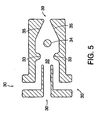
- static mixer 22 has a single outlet 39 and, after inlets 30, is axially symmetrical about the length of the static mixer.
- process materials pass through inlets 30 into a mixing region 32.
- baffle 33 which may be toroidally shaped.
- Baffle 33 creates a pressure differential and causes eddy formations from turbulence. These eddies are associated with very high Reynolds' numbers that may be necessary for mixing the process materials into a homogeneous solution.
- the process materials After passing through baffle 33, the process materials preferably pass around a flow disruption element 34.
- Flow disruption element 34 may be cylindrical and may be located along the centerline of static mixer 22.
- Flow disruption element 34 provides a second stage of agitation.
- Flow disruption element 34 may create Karmann vortices, which add to the turbulence by eddy generation.
- Following flow disruption element 34 is preferably a flow constriction region 35.
- Flow constriction region 35 compresses the process materials as they pass to an outlet 39.
- Flow constriction region 35 is preferred to be a tapered conical surface because this may decrease back pressure that might otherwise occur if the region decreased in diameter in a stepped fashion.
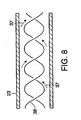
- Secondary static mixer 23 is preferably an in-line static mixer. Secondary static mixer 23 may contain a helical shaped feature 38. The helical shaped feature 38 may be, for example, manufactured from a twisted plastic sheet. Secondary static mixer 23 preferably provides constant agitation of the process materials. For slurry process materials in the semiconductor industry, secondary static mixer 23 is preferably operated at low enough flow rates that the helical path of secondary static mixer 23 will not cause detrimental shear rates, which may create particle growth and may cause significant micro scratching. Though is it highly dependent on the process material and the dimensions and geometry of secondary static mixer 23, a flow rate of about 100-250 ml/min is appropriate for some conditions. It should be understood that a mixer of the type described as secondary static mixer 23 may serve as static mixer 22 and that there need not be any secondary static mixer 23.
- Fluid flow diagrams illustrated in Figs. 6, 7 and 8 generated from basic fluid flow principles show, with flow lines 37, sufficient agitation throughout static mixer 22 and secondary static mixer 23 to ensure thorough mixing of process materials.
- blended process material may pass from static mixer 22 or secondary static mixer 23 through outlet line 17 to a point of use, such as process equipment 60.
- the point of use may be any machine, equipment, station or other location where a stream of blended of process materials is desired.
- the outlet line 17 may feed directly to process equipment 60 or to an outlet for use by an operator.
- static mixer 22 or secondary static mixer 23 may be located close to the point of use to minimize this loss.
- outlet line 17 may feed into a holding vessel 3 and blended process material may be fed from holding vessel 3 to points of use as needed.
- Storing the blended process materials in holding vessel 3 may allow the acceptability of the blended process materials to be tested before they are sent to a point of use. Instruments similar to those described above for analysis of chemical and slurry process materials may also be used to verify that the blended process materials are acceptable.
- the concentrations of individual process materials in a blend may also be tested independently with an appropriate device. For example, the concentrations of the various constituents may be measured with chromatography, such as gas chromatography. Storing the blended process material in holding vessel 3 may also allow simplification of the blending system, as described below.
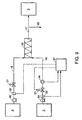
- FIG. 9 illustrates a relatively simple embodiment of the blending system of the present invention in which two materials, such as a slurry and DI water, may be blended.
- the process materials to be blended are initially stored in holding vessels 3.
- the process materials may be pumped from holding vessels 3 through material supply lines 18 to static mixer 22 by a pump 90.
- Valves 21 may be used to regulate the flow of each process material.
- one of the process materials may be supplied at a constant volumetric flow rate.
- one valve 21 may be left in a single position or an orifice of fixed geometry may be used to provide a constant volumetric flow rate of one of the process materials.
- the flow rate of the other process material may then be adjusted to provide a desired blend of process materials.
- a sensor 92 providing data allowing the volumetric flow rate to be converted to a mass flow rate may be included on material supply line 18.
- Sensor 92 may measure density or a property that may correlated to density, such as temperature.
- a controller 91 may receive a signal from sensor 92 representing a density of the process material and may calculate a mass flow rate of process material based upon this signal and the known volumetric flow.
- Controller 91 may also receive signals from a sensor 93 associated with the material supply line through which the volumetric flow rate varies. As with sensor 92, sensor 93 may provide a signal that represents a property that may allow the mass flow in the material supply line to be calculated based on a volumetric flow. As the volumetric flow rate of process material may vary, controller 91 may also receive a signal from a volumetric flow meter 94, allowing the mass flow rate to be calculated. Based upon the mass flow rate in the material supply line, controller 91 may control a valve 21 to provide a mass flow rate that, with the mass flow rate of process material in the other material supply line, provides a desired blend of process materials.
- sensor 93 and volumetric flow meter 94 may be eliminated by providing a sensor 96 downstream of static mixer 22 able to verify that the blended process material is acceptable.
- a densitometer, percent solids sensor, or the like may be used to verify that the blended process material is acceptable.
- Sensor 96 may provide a signal to controller 91 representing the condition of the blended process material. If necessary, controller 91 may adjust the flow rate of one of process materials with valve 21 until a signal representing a set point is achieved from sensor 96. For example, where the process materials are a slurry and DI water the density of the desired slurry/DI water blend may be the set point.
- sensors 96 may provide signals to the controller representing conditions of the blended process materials.
- the overall flow rate is generally not selectable. Accordingly, such embodiments may provide the blended process material to a holding vessel 3. Holding vessel 3 may contain a device or system to prevent settling or separation of the blended process materials, such as an agitator. In another embodiment, excess blended process material may be produced and what is needed may be supplied on demand with the remainder being discarded. Alternatively, the flow rate of the other process material may be adjusted as well, such that the overall flow rate of the blended process materials may be matched to the demand, as described previously.
- the blend may be diverted away from a point of use or holding vessel.
- the unacceptable or unneeded blend of process material may be sent to a drain 95 or otherwise disposed of.
- a drain or other disposal system may be used in any embodiment of the present invention where the blend of process material may be unacceptable or unneeded under some circumstances.
- a typical blend process includes the dilution of a high solids, concentrated silica slurry with DI water.
- One such commercially available slurry is the CABOT® SEMI-SPERSE TM 25 slurry, which is a colloidal suspension having 25 wt. % solids and a density range of 1.162-1.170 g/ml (1.166 ⁇ 0.004 g/ml).
- This slurry is a typical polishing slurry in wafer production used during the silica oxide layer, or oxide step, polish.
- the demand is assumed to be 200 milliliters per minute (ml/min) of the blended process materials.
- Typical polishing processes require a blend having a slurry to DI water ratio of 1:1 by mass or about 1:1.17 by volume, resulting in a final density of about 1.074 grams per milliliter (g/ml). Variations in the slurry may result from variations in the manufacturing of the base material. Furthermore, although an incompressible fluid, the density of water used in the manufacturing of the raw slurry also varies as does the density of the DI water blended with the slurry. Density values of DI water are known and readily available from technical reference publications. One such publication, The Handbook of Chemistry and Physics from CRC Press, Inc., states a density range of 0.99970 to 0.99565 g/ml for water over a temperature range of 50° to 86° F (10° to 30° C).
- the temperature of the supply of DI water from a facility generation plant ranges typically ranges from about 65° to 75° F (18° to 24° C). Accordingly, for purposes of this example, the density of DI water will be assumed to be 0.99821 g/ml (its listed density at 68° F (20° C)), however, in practice, this temperature could be monitored to provide an accurate density.
- volumetric mixing produces a higher risk of error in the blend than mass mixing. Accordingly, for a 1:1 by weight recipe, equal masses of each constituent are added resulting in about 1.00 ml of slurry concentrate and about 1.168 ml of DI water.
- both mass rates of concentrated slurry and deionized water are equal to one another and the ratio of each mass rate to the respective densities for each material yield the desired volumetric flow rate. This would generate the volumetric flow rates of about 92.064 ml/min (1.534 ml/sec) for the concentrated 25% solids slurry and about 107.928 ml/min (1.799 ml/sec) for the deionized water. Note that this application is good only for the constant density of slurry at 1.166 g/ml stated above.
- the communication of this value from the dispensing subsystem to the controller may adjust the flow controllers accordingly. For example, if the value of the density increased to 1.180 g/ml, the controller may regulate the flow rate by closing the valve to the appropriate degree. This in turn would decrease the absolute output flow rate, which in turn would be adjusted by increasing the deionized water flow rate. The specified endpoint flow rate and density would be substantially constant during these adjustments.
- Example 1 In order to demonstrate that the blending system of the present invention could produce acceptable blends of process material, the hypothetical blend of slurry and DI water described in Example 1 was performed using the blending system illustrated in FIG. 9. DI water was supplied from a holding vessel at a constant, known volumetric flow rate and its temperature was monitored and supplied to a controller that calculated a mass flow rate of the DI water. The slurry described in Example 1 was supplied from a second holding vessel. This slurry was tested and found to have a percent solids of 25.8 wt. % and a density of 1.151 g/ml. The density of the slurry and its volumetric flow rate were monitored and provided to a controller to calculate a mass flow rate of slurry. The slurry mass flow rate was adjusted with a valve by the controller to produce about a 1:1 mass ratio of DI water to slurry.
Landscapes
- Chemical & Material Sciences (AREA)
- Chemical Kinetics & Catalysis (AREA)
- Physics & Mathematics (AREA)
- Dispersion Chemistry (AREA)
- General Physics & Mathematics (AREA)
- Engineering & Computer Science (AREA)
- Automation & Control Theory (AREA)
- Fluid Mechanics (AREA)
- Accessories For Mixers (AREA)
- Grinding-Machine Dressing And Accessory Apparatuses (AREA)
- Finish Polishing, Edge Sharpening, And Grinding By Specific Grinding Devices (AREA)
- Mechanical Treatment Of Semiconductor (AREA)
Abstract
Description
- The present invention is directed to a method and apparatus for blending process materials and, particularly, to a method and apparatus for blending ultra-high purity chemicals, abrasive slurries and the like.
- Blended process materials are required, for example, in the pharmaceutical, cosmetic and semiconductor industries. In the semiconductor industry, blended process materials are typically prepared using batch production systems including a dispensing subsystem and a mixing subsystem. The dispensing subsystem transfers materials from a supply source to the mixing subsystem. Supply sources are typically containers designed for safe storage of a process material, such as a chemical or slurry. Other supply sources include facility generation plants, such as deionized (DI) water generation facilities or facilities for supplying other mass-consumed process materials, such as hydrogen peroxide or ammonium hydroxide. The facility generation plant may be directly connected to the dispensing subsystem. A single dispensing subsystem may connect to a variety of supply sources, transferring process material from each to the mixing subsystem.
- In the mixing subsystem, the process materials transferred by the dispensing subsystem are added to a mixing vessel or tank. Typically, the materials are added in a predetermined sequence, as required for a particular process. For example, the process may require a predetermined ratio of individual process materials to create a desired blend. The sequence of the process may be based on reactivity or safety, for example an acidic or basic solution is typically added after water. Alternatively, the sequence of the process may be based on the need to reduce or correct process variances, such as dilution of an excessively concentrated wafer polish slurry with DI water. In some cases, it may be necessary to interrupt the addition of a first process material to add a second process material, followed by resumption of addition of the first process material.
- The addition of process materials to the mixing vessel is typically monitored and regulated by measuring mass or volume differences. Typical mass difference regulated additions may involve the use of a scale on a holding vessel or tank. In this type of system, each process material is added individually, as an automated control system measuring the mass of the holding vessel is not able to discern the relative amounts of two process materials added simultaneously. Typical volume difference regulated additions may involve the use of flow meters.
- Once in the mixing vessel, the process materials are typically blended into a homogeneous solution with an impeller, forming a batch of blended process materials. The batch of blended process materials is typically then used for its intended application.
- Many conventional processes require precise addition of process materials to produce a batch of blended process materials that is acceptable for its intended application. Accordingly, the measuring instruments that monitor the inputs to the mixing vessel are typically very precise to insure batch-to-batch consistency. In many applications, even minor process variations may lead to significant differences in the batch of blended process materials, potentially rendering it useless for its intended application.
- DE 23 20 212 discloses a blending system and a method of blending materials.
- US-A-5 332 125 discloses a method and apparatus for metering flow of a two-component dispensing system.
- US-A-5 271 521 discloses a method and apparatus for compensating for changes in viscosity in a two-component dispensing system.
- In one embodiment, the present invention is directed to a blending system, according to
claim 1. The blending system further comprises a process control system including a first flow control device positioned on at least one of the first and the second material supply lines, a first sensor positioned downstream of the static mixer, and a controller comprising logic code to provide a control signal to the first flow control device based upon a sensor signal provided by the first sensor. - In another embodiment, the present invention is directed to a blending system according to
claim 11. The blending system also includes a process control system including a controller, an input device in communication with the controller to provide an input signal representing a desired blend of process materials, and a first valve connected to one of the plurality of material supply lines and to the controller. The blending system further includes a dispensing subsystem including a holding vessel having an inlet and an outlet, a recirculation line fluidly connected to the inlet and the outlet and a second valve fluidly connected to the recirculation line and to one of the plurality of material supply lines such that material from the recirculation line may be selectively diverted to the material supply line. - In another embodiment, the present invention is directed to a method of supplying blended process materials according to
claim 20. The method includes supplying a first process material through a first of material supply line, supplying a second process material through a second of material supply line, and blending the first and the second process materials in a static mixer fluidly connected downstream of the first and the second material supply lines. The method also includes regulating the supply of one of the first and the second process materials with a first valve positioned on one of the first and the second material supply lines based upon a sensor signal provided by a sensor positioned downstream of the static mixer. - In another embodiment, the present invention is directed to a method of supplying blended process materials according to
claim 23. The method includes supplying a plurality of process materials through a plurality of material supply lines and blending the plurality of process materials in a static mixer positioned downstream of the plurality of material supply lines. The method also includes regulating the supply of the plurality of process materials with a process control system including a controller, an input device, and a first valve connected to one of the plurality of material supply lines and to the controller. The input device is connected to the controller to provide an input signal representing a desired blend of process materials. The method further includes holding one or more of the plurality of process materials in a holding vessel having an inlet and an outlet, recirculating the one or more of the plurality of process materials in a recirculation line connected to the holding vessel inlet and outlet, and diverting a portion of the one or more of the plurality of process materials into one of the plurality of material supply lines with a second valve connected to the recirculation line and to the one or more of the plurality of material supply lines. - Preferred, non-limiting embodiments of the present invention will be described by way of example with reference to the accompanying drawings, in which:
- FIG. 1 is a block diagram of one embodiment of the apparatus of the invention;
- FIG. 2 is a block diagram of another embodiment of the apparatus of the invention;
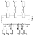
- FIG. 3 is a block diagram of another embodiment of the apparatus of the invention;
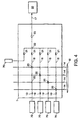
- FIG. 4 is a block diagram of another embodiment of the apparatus of the invention;
- FIG. 5 is a cross-sectional view of one embodiment of the static mixer of the invention;
- FIG. 6 is a cross-sectional view of the embodiment of the static mixer of the invention illustrated in FIG. 5, with illustrated flow path through the chamber;
- FIG. 7 is a perspective, cross-sectional view of the embodiment of the static mixer of the invention illustrated in FIG. 5, with illustrated flow path through the chamber;
- FIG. 8 is a cross-sectional view of one embodiment of the secondary static mixer of the invention, with illustrated flow path through the chamber;
- FIG. 9 is a block diagram of another embodiment of the apparatus of the invention;
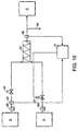
- FIG. 10 is block diagram of another embodiment of the apparatus of the invention;
- FIG. 11 is a graph of percent solids versus trial number; and
- FIG. 12 is a graph of density versus trial number.
- The present invention is directed to a system for blending process materials. The blending system is suitable for blending and supplying process materials on demand to a point of use or for providing a blend of process materials for later use. By process materials it is meant any fluid material capable of being transported through a conduit. For example, process materials may include water, various chemicals, solutions, suspensions of solids, slurries or any such other materials. While the blending system of the present invention is for use with any process requiring blended process materials, it is particularly applicable to the blending of ultra high purity chemicals and abrasive slurries and other blending applications were accuracy and precision are desired. For example, the present invention is particularly useful in the semiconductor, cosmetic and pharmaceutical industries.
- An embodiment of the blending system of the invention includes a plurality of material supply lines, a static mixer positioned downstream of the plurality of material supply lines and a process control system.
- The plurality of material supply lines may be any conduits for carrying process materials. For example, material supply lines may be pipes, channels or other devices for directing fluid flow. The plurality of material supply lines may supply many different process materials from a variety of sources. For example, material supply lines may supply process materials from storage containers or from facility generation plants. In some instances, the material supply lines may supply process materials from a dispensing subsystem.
- In some embodiments including a dispensing subsystem, the dispensing subsystem may consist of a holding vessel, a recirculation line and a valve. The recirculation line may be fluidly connected to the inlet and the outlet of the holding vessel to provide continuous circulation of process material through the recirculation line. This flow may be provided by a device for inducing fluid flow, such as a pump. The valve in the dispensing subsystem may be connected to the recirculation line and to a material supply line, such that process material may be diverted from the recirculation line to the material supply line.
- The static mixer of the blending system of the present invention is in fluid communication with the plurality of material supply lines. For example, the static mixer includes a plurality of inlets, each connected to one of the plurality of material supply lines. The static mixer also includes a mixing region and an outlet. Process materials are received from the material supply lines at the inlets of the static mixer and passed to the mixing region. The mixing region is shaped to cause agitation and mixing of the process materials flowing through it. After mixing, the process materials pass through the outlet, which is connected to a point of use or storage vessel. Points of use are any location where there is demand for a supply of blended process materials. For example, points of use may include process machinery or work stations.
- In some embodiments, the process control system of the blending system of the invention may include a controller, an input device and a valve. In other embodiments, the process control system may include a controller, a sensor and a valve. It should be appreciated that valves are discussed herein for controlling flow by way of example only; any flow control device may be substituted for any valve in the invention. By flow control device, it is meant any device that is able to provide a desired level of flow control, such as various types of valves, pumps and other pressure modifying devices.
- The controller may be any device capable of receiving information and acting upon the information based upon a series of protocols, such as logic code. For example, the controller may be a microprocessor based device, such as a computer. Where the process control system includes one, the input device may be connected to the controller to provide an input signal representing a desired blend of process materials. The input device may be any device capable of receiving information and relaying it to the controller. For example, the input device may be a potentiometer, key pad or Supervision Control And Data Acquisition (SCADA) node.
- The valve or valves of the process control system may be connected to one or more material supply lines and to the controller. For example, a valve may be positioned along a material supply line so as to control flow through or into the material supply line and may be controlled by the controller. Accordingly, the controller may control flow through or into the material supply line with the valve in accordance with a desired blend of process materials supplied at the input device. Alternatively, or additionally, the controller may control flow through or into the material supply line based on a signal provided by the sensor.
- Viewing the blending system of the invention as a whole, it will now be clear that embodiments of the blending system are capable of supplying a desired blend of process materials based on a user specified input. This blend of process materials may be supplied on a continuous basis, without interruption. Additionally, the blended process materials may be supplied on an as-needed basis, eliminating the need to store the blended process materials. It will also be recognized that the controller may receive additional input to aid the blending process. For example, the controller may be supplied with information from process appropriate sensors regarding the process materials or process conditions. Such sensors may be located anywhere in the blending system, such as in a dispensing subsystem, on a material supply line, or even downstream of the static mixer. It will also be recognized that the controller may also control other aspects of the blending process. For example, the controller may be connected to devices or systems for modifying the properties of the process materials, and may selectively operate these devices or systems based on input received from sensors regarding the condition of the process materials or from an operator or other outside source.
- The present invention is adaptable for use in a wide variety of applications. The embodiment of the invention may vary depending on the application. For example, where monitoring of the process materials is desired, sensors may be used, and these sensors may vary with the process materials. Similarly, the construction of the blending system, such as piping, tubing, and wetted surfaces of instruments and pumps may be adapted to particular process materials. For example, where such process materials may be abrasive or corrosive, such as the polishing slurries and chemicals often employed in the semiconductor industry, these structures may be formed of plastic materials such as fluropolymers.
- Referring now to the figures, and in particular to FIG. 1, one illustrative embodiment of the invention is shown. In FIG. 1, a
dispensing subsystem 2 is coupled to amixing subsystem 1. Thedispensing subsystem 2 includes equipment to continuously dispense a process material from a holdingvessel 3 to mixingsubsystem 1, such as apump 4 and arecirculation line 14. From holdingvessel 3, the process material may be pumped bypump 4 throughrecirculation line 14 to mixingsubsystem 1. As illustrated in FIG. 4, which is a block diagram of mixingsubsystem 1,recirculation line 14 passes through mixingsubsystem 1. In mixingsubsystem 1, avalve 20 positioned onrecirculation line 14 may connectrecirculation line 14 to amaterial supply line 18.Valve 20 may be actuated to divert process material fromrecirculation line 14 tomaterial supply line 18 which, in turn, may deliver the process material to astatic mixer 22. Process material that is not diverted byvalve 20 remains inrecirculation line 14 and is returned to holdingvessel 3. - Holding
vessel 3 may be any storage container able to hold sufficient process material to feed a blending process. For convenience, it is preferred that holdingvessel 3 be the container that the process material is delivered and/or stored in. For example, holdingvessel 3 may be a tank, such as a 55 gallon drum or other common storage vessel. In some embodiments, holdingvessel 3 may include an agitator, such as a sparger head or an impeller. An agitator is particularly appropriate where the process materials may settle or separate. -
Pump 4 may be any device of any construction that will provide adequate flow of the process material inrecirculation line 14. For example, pump 4 may be pneumatically or electrically operated and may be a positive displacement pump, utilizing a bellows or diaphragm construction.Pump 4 may be constructed of materials compatible with the process material being pumped. Examples of suitable pumps include ASTI pumps available from Saint Gobain Performance Plastics of Garden Grove, CA and ARO pumps available from Ingersoll-Rand of Woodcliff Lake, NJ. - If process material is diverted from
recirculation line 14 tomaterial supply line 18, there may be a loss of pressure inrecirculation line 14, despite the continued action ofpump 4. Accordingly, a second manner of adjusting pressure may be used. For example, aback pressure valve 100 may be installed inrecirculation line 14 and regulated to maintain a desired pressure inrecirculation line 14, despite transfer of process material tomaterial supply line 18. - In order to supply usable process material to mixing
subsystem 1, dispensingsubsystem 2, may include systems or apparatus for monitoring and/or modifying properties of the process materials in mixingsubsystem 1. For example, properties that verify that the process materials are acceptable for blending may be monitored and/or modified. Monitoring or modification systems may include a variety of instruments. Referring now also to FIG. 2, dispensingsubsystem 2 may include instruments, such asinstruments recirculation line 14. The instruments may vary based on the process material supplied to mixingsubsystem 1 and the tolerances of the intended application for the blended process materials. For example, instruments for monitoring density, pH, particulates, oxidation and reduction potential, conductivity, index of refraction or other process conditions may be appropriate for a given application. Any instrument that provides the desired feedback may be used. For example, density may be monitored with adensitometer 5, or pH with apH probe 6. - By way of example, slurries in semiconductor processes will be described. In semiconductor processes, slurries are used as polishing medium in the manufacture of semiconductor wafers. Slurries are also used to polish optical lenses and other disk related items. The polishing effect of slurries results from fine, inert, abrasive particles suspended in a liquid. Typical abrasives in slurries used in the semiconductor industry are silica, alumina and ceria. Abrasives for slurries are manufactured and sorted into particle size ranges. Typical slurries include particles in a range from 0.05 micron to 0.30 micron in diameter and contain greater than 1012 particles per cubic centimeter.
- For monitoring a slurry in a semiconductor process, an instrument for continuously measuring mass density (herein after all densities refer to mass density unless specifically indicated otherwise), such as
densitometer 5, may be preferred. Measuring density is one manner of tracking concentration. For example, in slurries, the density is related to the amount of inert, non-volatile solids per unit volume. Accordingly, by measuring volumetric flow rate per unit time, for example with a flow meter, and density, the amount of inert solids delivered to a blend of process materials may be monitored. Monitoring density may also be a preferred for a slurry in a semiconductor process because density measuring instruments may produce less agglomeration than other instruments providing similar feedback because they may not introduce the same shear stresses in the slurry. A sufficiently accurate mass flow meter that does not produce unacceptable agglomeration or a percent solids sensor also may be used for this purpose. - In slurry processes, an instrument for measuring pH, such as a pH sensor, also may be used. If the pH of the slurry is higher than acceptable, the slurry may be too aggressive and may remove unintended materials from the wafer. Conversely, if the pH is too low, intended materials may not be removed.
- By way of another example, chemicals used in semiconductor processes will be described. In semiconductor processes, various chemicals are used as reactants and oxidizers for wafer polishing, as well as in scrubbing solutions, post cleaning solutions and developer solutions. These chemicals are typically shipped in raw, concentrate form. Typical chemicals used for polishing include hydrogen peroxide, potassium hydroxide and ammonium hydroxide. Hydrogen peroxide is used as an oxidizer for metal layers on a wafer. Controlling the amount of hydrogen peroxide in a blend of process materials controls the rate material is removed from the wafer surface. Typically, hydrogen peroxide is blended from a 30 weight percent (wt. %) solution to a few percent, such as 2 to 4 wt. %, solution. Potassium hydroxide is used in inter layer dielectric polishing steps for controlling the pH of a blend of process materials to provide desired polishing of silica dioxide layers. Hydrogen peroxide and ammonium hydroxide mixtures are typically used as cleaning and scrubbing solutions. If these mixtures remain unused, the hydrogen peroxide and ammonium hydroxide decompose into water and ammonia. Accordingly, producing these mixtures as they are used according to the present invention is preferred.
- For the distribution of bulk chemicals for use in the semiconductor industry, it is preferred that
instruments recirculation line 14 to assure acceptable material is being transmitted. One of the preferred instruments for monitoring acceptability of a chemical process material is an instrument that measures the density of the process material on a continuous basis, such asdensitometer 5. Monitoring the density of a chemical process material, as with monitoring the density of a slurry, may make it possible to gauge the concentration of the process material prior to dispensing it to mixingsubsystem 1. Alternatively, where density correlates well with temperature, a thermocouple or other temperature probe may replace the densitometer. - Other instruments that may be useful for the measurement and monitoring of a chemical process material, and are preferred for such processes in the semiconductor industry, are instruments for determining concentration and reactivity, such as
conductivity sensors 9 and oxidation and reduction potential (ORP)sensors 8, respectively. Conductivity may be used to measure chemical concentration by correlating the two. For many common process materials, tables exist relating conductivity to concentration. Accordingly, by monitoring the conductivity of the process material, it may be possible to monitor its concentration. Monitoring the ORP of the process material may allow detection of sudden changes in chemical reactivity.ORP sensors 8 operate similarly topH probes 6, however,ORP sensors 8 may measure the properties of liquids, such as hydrofluoric acid, that may deteriorate typical pH probes. Refractive index sensors may also be useful in determining concentration as the refractive index of the material also may be correlated to the concentration. - Another process material property that is of particular importance in high purity applications, such as the semiconductor industry, is the level of particulates. For example, the manufacturing of wafers requires ultra-high purity process materials. Particulates generated from holding
vessel 3, or from the manufacturing of the process material, may contaminate the process material and the product. Strict guidelines for particle sizes and the number of particles of a particular size may be required for a semiconductor process to be economically feasible. Accordingly, for processes that are sensitive to particulates, an instrument for measuring particulate levels in a process material, such as on-line or in-line particle counter 7, may be used. Particle counters 7 may find utility both within dispensingsubsystem 2 and between dispensingsubsystem 2 andmixing subsystem 1, where they may verify that process material from dispensingsubsystem 1 has an acceptably low particle level. Particle counters 7 may also be used to verify that a blend of process materials from the static mixer has an acceptably low particle level. - An in-
line particle counter 7 typically includes a flow cell mounted directly in a process line, such asrecirculation line 14. In-line particle counter 7 monitors particles passing through the flow cell. In-line particle counter 7 typically measures particles per volume and, if the volumetric flow rate varies, the reported particle count may vary. Accordingly, the rate at which material travels throughparticle counter 7 may be regulated to deliver an accurate particle count For example, for accurate in-line particle counting, a measurement cell may be connected to a junction of a process line. The junction may divert a stream of fluid through the measurement cell and allow the flow rate throughcounter 7 to be adjusted to a desired level. Typically, the flow rate throughcounter 7 is adjusted to about 100 milliliters per minute (ml/min). - Because it is generally mounted directly in a process line, an in-
line particle counter 7 typically may only monitor the particle level in that process line. Alternatively, the in-line particle counter 7 may be connected to multiple process lines by a switching mechanism and process material from any of these lines may be redirected toparticle counter 7 for monitoring. However, if the flow rates from the multiple process lines are not identical, readings fromparticle counter 7 for each of the process lines will not be in the same volume scale. - In an on-
line particle counter 7,particle counter 7 need not be on a process line. Instead, samples from various process lines may be routed through a system for handling multiple streams, such as manifold, and to counter 7. The samples may be pulled into a sample collector, such as a small, closed loop, insuring that the volume of each sample is the same. Because the volume of each sample is the same, the particle readings for each process line may be in the same volume scale and may be compared. Accordingly, an on-line particle counter 7 allows more process lines, or points in a process line, to be easily monitored and compared. - A process control system for controlling
dispensing subsystem 2 and/or mixingsubsystem 1 may operate based on the process and on the process material properties. For example, information gathered from instruments may be fed to a controller associated with a process control system connected tovalve 20 and/or may be presented to an operator who may identify and correct problems. Presentation to an operator may occur in any form that will get the attention of the operator as desired, such as an output monitor or an alarm. Where the controller is connected tovalve 20, the amount of process material that is diverted fromrecirculation line 14 tomaterial supply line 18 may be selected by the controller based on the process for a given blend of process materials. Accordingly, the controller may be capable of modifying a blend of process materials by altering the flow rate throughvalve 20, or it may be able to correct for deviations in the process material being diverted fromrecirculation line 14. For example, ifpH sensor 6 detects that the pH of a process material being used to acidify a blend of process materials has risen (a deviation), the controller may receive a signal alerting it to this fact and may divert additional process material fromrecirculation line 14 tomaterial supply line 18 so that the pH of the blended process materials remains constant. Alternatively, if a change in flow rate will not correct the detected deviation, the process may be halted and the material held withindistribution subsystem 2 until appropriate correction may be made. - Where adjusting the flow rate of process material from
recirculation line 14 tomaterial supply line 18 may be insufficient to correct a deviation, it is preferred thatrecirculation line 14 have one or more systems or apparatus for correcting the deviation. These systems or apparatus may include treatment devices. For example, where unacceptable particulate levels may be detected inrecirculation line 14, it is preferred that one ormore particle separators recirculation line 14.Particle separators - In the embodiment illustrated in FIG. 2, continuous feedback from an online or
inline particle counter 7 may supply information to a controller for monitoring the particle level inrecirculation line 14. At start-up, or whenever the particle level has been detected to exceed a pre-set threshold,valves 12 may be actuated by the controller or an operator to bypassrecirculation line 14 and to redirect the process material through abypass line 13. As the process material circulates inbypass line 13, a filter, such as arough filter 10, may reduce the particle level in the process material. When the particle level falls to within the pre-set threshold, the controller may either actuatevalves 12, or alert an operator who may actuate them, ending the bypass and allowing the process materials to pass throughrecirculation line 14 where they may be diverted tomaterial supply line 18. In applications requiring very low particulate levels, it is preferred that apolish filter 11 also be located alongrecirculation line 14. The use of abypass line 13 withrough filter 10 and polishfilter 11 onrecirculation line 14 is preferred for the distribution of bulk chemicals for use in the semiconductor industry described above. As illustrated in FIG. 1,filter bypass line 13 to provide constant particle removal fromrecirculation line 14. Furthermore, a bypass line may be used in systems designed to modify properties other than particulate levels. - Referring now to FIG. 3, in a large production facility using many process materials, such as multiple slurries and chemicals in a semiconductor processing facility,
many dispensing subsystems 2 may be connected to aline network 16. Inline network 16, each process material may be contained in arecirculation line 14. In some embodiments, eachrecirculation line 14 may be contained in a secondary line structure to prevent leaks and to promote safety where the process materials may be hazardous. - In industries requiring high purity, such as the semiconductor industry, dispensing
subsystems 2 are preferably housed in semi-clean rooms, sub-fab, or a particular class clean room.Recirculation lines 14 are preferably run from dispensingsubsystem 2 to a clean room environment where mixingsubsystem 1 andprocess equipment 60 are located.Process equipment 60 may be connected to mixingsubsystem 1 by anoutput line 17. - Referring now to FIG. 4, as previously described, each
recirculation line 14 may be routed through mixingsubsystem 1. Eachrecirculation line 14 may connect to amaterial supply line 18 via avalve 20. Also as previously described,valve 20 may allow fluid to flow fromrecirculation line 14 intomaterial supply line 18 and then tostatic mixer 22 without diverting all of the process material in thematerial supply line 18.Multiple valves 20 may be used to allow multiple connections to a singlematerial supply line 18, resulting in limited mixing of process materials inmaterial supply line 18.Valve 20 is preferably a slip stream valve and may operate in any manner, such as pneumatically from an air supply or solenoidally through an electronic actuation device. In processes, such as semiconductor processes, where the process materials may be flammable,valves 20 are preferably energized from a pneumatic source for safety and fire hazard prevention purposes. - In mixing
subsystem 1,material supply lines 18 may carry process materials directly from facility generation plants 70. Flow of the process material fromfacility generation plant 70 intomixing subsystem 1 may be controlled by avalve 19.Other valves 20 may be positioned alongmaterial supply line 18 and connected to arecirculation line 14 to allow a second process material to be added to the process material fromfacility generation plant 70. The combined process materials are then be fed tostatic mixer 22. For example, water may be delivered fromfacility generation plant 70 inmaterial supply line 18. A process material fromrecirculation line 14 may then be added tomaterial supply line 18 atvalve 20, resulting in diluted process material inmaterial supply line 18. The diluted process material passes tostatic mixer 22. In some embodiments, it may be preferred thatmaterial supply lines 18 be kept under constant flow conditions to inhibit the build up of contaminants, such as solids and bacteria. Rather than continuously flowing more costly or dangerous process materials throughmaterial supply lines 18 in such an embodiment, DI water or another relatively inert material may be run through lines not presently supplying process material. Havingmaterial supply lines 18 connected to a source of DI water may also aid in cleaning and maintenance ofmaterial supply lines 18. - Flow of process materials to
static mixer 22 frommaterial supply lines 18 may be regulated with avalve 21. Where process materials are being adding tomaterial supply line 18 containing another material, the flow rates and related pressures in the various lines are preferably controlled to insure that the process materials flow at the desired rate and in the desired direction. -
Dispensing subsystem 2 andmixing subsystem 1 may be controlled manually or electronically. Preferably, dispensingsubsystem 2 andmixing subsystem 1 are connected to a process control system including a controller (most typically, a central processing unit (CPU) with memory, such as a programmable logic controller (PLC)). An input device may allow a desired blend of process materials to be specified by a user. For example a key pad or computer terminal may be used to specify a given blend of process materials to the controller. The controller may receive signals from process equipment to continuously monitor, for example, incoming process materials, process conditions and the safety of personnel. The controller may interpret the input from the input device and the signals from the process equipment to control dispensingsubsystem 2 andmixing subsystem 1 to produce the specified blend of process materials. For example, a Supervision Control And Data Acquisition (SCADA) system may be used to control dispensingsubsystem 2 andmixing subsystem 1. Such a controller may store quality control data, information on usage of the system, alarm information or other process information. Furthermore, the controller may facilitate statistical process control by maintaining historical data that may be correlated to process output to determine trends and spot problems. A process control system may be designed so that an operator may be physically removed from the process equipment, particularly where the process or process materials may be dangerous. - A typical process control system includes a plurality of pumps, valves, instruments, and monitoring switches. These components may play multiple roles in the operation of the system. For example, fluid pressure drop across a filter may be monitored to determine if the filter needs to be cleaned or replaced. The same pressure measurement devices that monitor the pressure drop across the filter may also provide data on the absolute pressure in the process line.
- Process control systems may display the process graphically on a monitor, allowing observation of key features of the process. This graphical display may allow an operator to view all subsystems and process diagrams on an overview screen. In general, each piece of process equipment may be described graphically in an overall schematic displaying all connections, endpoints, and subsystems. From the overview screen, each subsystem may be selected and a separate screen opened displaying the features of that subsystem.
- The process control system may also provide feedback, such as an alarm, to an operator for maintenance or safety. In the above example of monitoring pressure differential across a filter, if the pressure differential surpasses a certain set point, an alarm may notify an operator, for example on the graphical display, to clean or change the filter. If the condition causing the alarm is not alleviated within a set period of time, a critical alarm may be activated, which may result in additional notification of the alarm condition or automatic action on the part of the process control system, such as shut down of the process.
- Because the flow rate, pressure and other properties, such as concentration or density, of the process material in
recirculation line 14 may affect both the flow of process material throughvalve 20 intomaterial supply line 18 and the amount of process material required, this data may be supplied to the controller. The controller may regulate the speed ofpump 4, and other devices in dispensingsubsystem 2, to ensure the proper amount of process material passes intomaterial supply line 18. Alternatively,valve 20 may be regulated based on this data to control the flow of process material intomaterial supply line 18. - The flow rate of process material into the
material supply line 18 may also be dependant on the flow rate and pressure of any process material, such as water, that is already present inmaterial supply line 18. Accordingly, it is preferred that this data also be supplied to the controller. The controller may adjustvalves recirculation line 14 withpump 4, to obtain a desired flow rate and composition inmaterial supply line 18. Because of the amount of data that may be supplied to the controller, and the number of variables that may be controlled based on this data, it is preferred that the controller comprise one or more microprocessors that are able to interpret the data and act on it based on set protocols to produce a desired blend of process materials. However, this function may also be performed by operators or by analog controls. - Mixing
subsystem 1 may be controlled according to mass or volume flow rates, or by a combination thereof, depending on the materials involved. Because it is typically more accurate, mass flow rates are preferred. Flow control forprocess valves - In the semiconductor industry, several constituents from dispensing
subsystems 2 including, for example, slurries, chemicals, and/or DI water fromfacility generation plant 70, may go into a given blend of process materials. The components of the blend may be specified through a user interface that may be a SCADA node. Typical processes call for an abrasive slurry to be diluted with DI water for inter layer dielectric polishing steps. Other typical processes call for an abrasive slurry, oxidizer, and DI water for polishing of metal layers. These processes may call for a variety of abrasives, oxidizing chemicals, dilutants, and amounts thereof depending an the process and may change frequently. - In such a semiconductor process system,
material supply lines 18 may carry DI water fromfacility generation plant 70 for diluting process materials and for flushingmaterial supply lines 18 andstatic mixer 22 when necessary. Eachmaterial supply line 18 may send DI water throughvalves static mixer 22. As mentioned previously, the DI water inputs preferably keep eachmaterial supply line 18 under constant flow, avoiding particulates and bacteria formation. When a process includes slurry process material,valve 20 may be actuated to expose water inmaterial supply line 18 to the slurry process material from arecirculation line 14.Valve 19 preferably regulates the flow of DI water to ensure flow from therecirculation line 14 atvalve 20 will flow tovalve 21.Valve 21 regulates the slurry flow rate tostatic mixer 22. The flow rate may depend on the amount of slurry required and density of the slurry. Similarly, where a process calls for a chemical process material from arecirculation line 14,valve 20 may be actuated to expose water inmaterial supply line 18 to the chemical process material. The flow rate may depend on the amount of chemical process material required and density, concentration or other properties of the chemical process material. - Process materials from
material supply lines 18 may continuously pass intostatic mixer 22 for mixing. The process materials may enterstatic mixer 22 through any apparatus that allows all of the process materials required for a process to be fed concurrently. Referring to FIGS. 5, 6, and 7,static mixer 22 may includemultiple inlets 30 connected tomaterial supply lines 18.Inlets 30 may be connected tomaterial supply lines 18 leading directly from facility generation plants 70,material supply lines 18 leading fromrecirculation lines 14 ormaterial supply lines 18 that receive inputs from both sources. In the semiconductor industry,material supply lines 18 typically carry slurry process materials, chemical process materials and DI water tostatic mixer 22. -
Static mixer 22 may be constructed in any manner that results in sufficient mixing of the process materials. Preferably, this mixing is accomplished by constructingstatic mixer 22 such that the process materials are subjected to turbulent flow conditions. For example,static mixer 22 may include one or more baffles or other flow disruption elements. For processes using slurries or other shear sensitive materials,static mixer 22 may be constructed so that mixing is gentle enough to not harm the materials being mixed, yet vigorous enough for thorough mixing. For example, in slurries used for polishing in the semiconductor industry, introduction of high shear rates may create particle growth and may cause significant micro scratching. Accordingly, for these slurries,static mixer 22 is preferably constructed in a manner that will result in relatively gentle mixing. A typical static mixer, such as static mixer including a helical flow disruption element, may be acceptable in some embodiments. - In the embodiment illustrated in FIGS. 5, 6 and 7,
static mixer 22 has asingle outlet 39 and, afterinlets 30, is axially symmetrical about the length of the static mixer. In this embodiment, process materials pass throughinlets 30 into a mixingregion 32. As the fluids mix and move under pressurized conditions, they travel through abaffle 33, which may be toroidally shaped.Baffle 33 creates a pressure differential and causes eddy formations from turbulence. These eddies are associated with very high Reynolds' numbers that may be necessary for mixing the process materials into a homogeneous solution. After passing throughbaffle 33, the process materials preferably pass around aflow disruption element 34.Flow disruption element 34 may be cylindrical and may be located along the centerline ofstatic mixer 22.Flow disruption element 34 provides a second stage of agitation.Flow disruption element 34 may create Karmann vortices, which add to the turbulence by eddy generation. Followingflow disruption element 34 is preferably aflow constriction region 35.Flow constriction region 35 compresses the process materials as they pass to anoutlet 39.Flow constriction region 35 is preferred to be a tapered conical surface because this may decrease back pressure that might otherwise occur if the region decreased in diameter in a stepped fashion. - Referring to FIG. 8, the process materials passing through
outlet 39 ofstatic mixer 22 may enter a secondarystatic mixer 23. Secondarystatic mixer 23 is preferably an in-line static mixer. Secondarystatic mixer 23 may contain a helical shapedfeature 38. The helical shapedfeature 38 may be, for example, manufactured from a twisted plastic sheet. Secondarystatic mixer 23 preferably provides constant agitation of the process materials. For slurry process materials in the semiconductor industry, secondarystatic mixer 23 is preferably operated at low enough flow rates that the helical path of secondarystatic mixer 23 will not cause detrimental shear rates, which may create particle growth and may cause significant micro scratching. Though is it highly dependent on the process material and the dimensions and geometry of secondarystatic mixer 23, a flow rate of about 100-250 ml/min is appropriate for some conditions. It should be understood that a mixer of the type described as secondarystatic mixer 23 may serve asstatic mixer 22 and that there need not be any secondarystatic mixer 23. - Fluid flow diagrams illustrated in Figs. 6, 7 and 8 generated from basic fluid flow principles show, with
flow lines 37, sufficient agitation throughoutstatic mixer 22 and secondarystatic mixer 23 to ensure thorough mixing of process materials. - In one embodiment, blended process material may pass from
static mixer 22 or secondarystatic mixer 23 throughoutlet line 17 to a point of use, such asprocess equipment 60. The point of use may be any machine, equipment, station or other location where a stream of blended of process materials is desired. Theoutlet line 17 may feed directly to processequipment 60 or to an outlet for use by an operator. For process materials that have a limited life span or may otherwise lose value during transport throughoutlet line 17,static mixer 22 or secondarystatic mixer 23 may be located close to the point of use to minimize this loss. - In an alternate embodiment, for example as illustrated in FIGS. 9 and 10,
outlet line 17 may feed into a holdingvessel 3 and blended process material may be fed from holdingvessel 3 to points of use as needed. Storing the blended process materials in holdingvessel 3 may allow the acceptability of the blended process materials to be tested before they are sent to a point of use. Instruments similar to those described above for analysis of chemical and slurry process materials may also be used to verify that the blended process materials are acceptable. The concentrations of individual process materials in a blend may also be tested independently with an appropriate device. For example, the concentrations of the various constituents may be measured with chromatography, such as gas chromatography. Storing the blended process material in holdingvessel 3 may also allow simplification of the blending system, as described below. - FIG. 9 illustrates a relatively simple embodiment of the blending system of the present invention in which two materials, such as a slurry and DI water, may be blended. In this embodiment, the process materials to be blended are initially stored in holding
vessels 3. The process materials may be pumped from holdingvessels 3 throughmaterial supply lines 18 tostatic mixer 22 by apump 90.Valves 21 may be used to regulate the flow of each process material. To simplify the blending system, one of the process materials may be supplied at a constant volumetric flow rate. For example, onevalve 21 may be left in a single position or an orifice of fixed geometry may be used to provide a constant volumetric flow rate of one of the process materials. The flow rate of the other process material may then be adjusted to provide a desired blend of process materials. - Where one of the process materials is maintained at a constant volumetric flow rate, a
sensor 92 providing data allowing the volumetric flow rate to be converted to a mass flow rate may be included onmaterial supply line 18.Sensor 92 may measure density or a property that may correlated to density, such as temperature. For example, acontroller 91 may receive a signal fromsensor 92 representing a density of the process material and may calculate a mass flow rate of process material based upon this signal and the known volumetric flow. -
Controller 91 may also receive signals from asensor 93 associated with the material supply line through which the volumetric flow rate varies. As withsensor 92,sensor 93 may provide a signal that represents a property that may allow the mass flow in the material supply line to be calculated based on a volumetric flow. As the volumetric flow rate of process material may vary,controller 91 may also receive a signal from avolumetric flow meter 94, allowing the mass flow rate to be calculated. Based upon the mass flow rate in the material supply line,controller 91 may control avalve 21 to provide a mass flow rate that, with the mass flow rate of process material in the other material supply line, provides a desired blend of process materials. - In an alternate embodiment, for example as illustrated in FIG. 10,
sensor 93 andvolumetric flow meter 94 may be eliminated by providing asensor 96 downstream ofstatic mixer 22 able to verify that the blended process material is acceptable. For example, where a slurry and DI water are blended, a densitometer, percent solids sensor, or the like may be used to verify that the blended process material is acceptable.Sensor 96 may provide a signal tocontroller 91 representing the condition of the blended process material. If necessary,controller 91 may adjust the flow rate of one of process materials withvalve 21 until a signal representing a set point is achieved fromsensor 96. For example, where the process materials are a slurry and DI water the density of the desired slurry/DI water blend may be the set point. If this density is detected to be too low, more slurry may be added and, if it is detected to be too high, the amount of slurry being added may be reduced. In some embodiments,several sensors 96, of different or similar types, may provide signals to the controller representing conditions of the blended process materials. - In any embodiment where one of the process materials is fed at a constant flow rate and the flow rate of the other process material is adjusted to produce a desired blend, the overall flow rate is generally not selectable. Accordingly, such embodiments may provide the blended process material to a holding
vessel 3. Holdingvessel 3 may contain a device or system to prevent settling or separation of the blended process materials, such as an agitator. In another embodiment, excess blended process material may be produced and what is needed may be supplied on demand with the remainder being discarded. Alternatively, the flow rate of the other process material may be adjusted as well, such that the overall flow rate of the blended process materials may be matched to the demand, as described previously. - During start-up, or any other time that a blend of process materials may not be acceptable or needed, the blend may be diverted away from a point of use or holding vessel. For example, the unacceptable or unneeded blend of process material may be sent to a
drain 95 or otherwise disposed of. A drain or other disposal system may be used in any embodiment of the present invention where the blend of process material may be unacceptable or unneeded under some circumstances. - The present invention will be further illustrated by the following examples which are intended to be illustrative in nature and not considered as limiting to the scope of the appended claims.
- A typical blend process includes the dilution of a high solids, concentrated silica slurry with DI water. One such commercially available slurry is the
CABOT® SEMI-SPERSE ™ 25 slurry, which is a colloidal suspension having 25 wt. % solids and a density range of 1.162-1.170 g/ml (1.166± 0.004 g/ml). This slurry is a typical polishing slurry in wafer production used during the silica oxide layer, or oxide step, polish. For purposes of this example, the demand is assumed to be 200 milliliters per minute (ml/min) of the blended process materials. - Typical polishing processes require a blend having a slurry to DI water ratio of 1:1 by mass or about 1:1.17 by volume, resulting in a final density of about 1.074 grams per milliliter (g/ml). Variations in the slurry may result from variations in the manufacturing of the base material. Furthermore, although an incompressible fluid, the density of water used in the manufacturing of the raw slurry also varies as does the density of the DI water blended with the slurry. Density values of DI water are known and readily available from technical reference publications. One such publication, The Handbook of Chemistry and Physics from CRC Press, Inc., states a density range of 0.99970 to 0.99565 g/ml for water over a temperature range of 50° to 86° F (10° to 30° C). The temperature of the supply of DI water from a facility generation plant ranges typically ranges from about 65° to 75° F (18° to 24° C). Accordingly, for purposes of this example, the density of DI water will be assumed to be 0.99821 g/ml (its listed density at 68° F (20° C)), however, in practice, this temperature could be monitored to provide an accurate density.
- Since the density of the two components may vary, volumetric mixing produces a higher risk of error in the blend than mass mixing. Accordingly, for a 1:1 by weight recipe, equal masses of each constituent are added resulting in about 1.00 ml of slurry concentrate and about 1.168 ml of DI water.
- In a dynamic situation of recipe blending, the materials must be displaced at rates whose sum equates to 200 ml/min or 3.33 ml/sec. Using the above stated, nominal density of 1.074 g/ml and desired blend flow rate of 200 ml/min or 3.3 ml/s, a mass rate of about 1.789 g/sec is the desired final product.
- Since this simple application involves equal masses of the two constituents, adjusting the flow rate of the supply streams of both slurry and water individually may control the final projected fluid stream. Ideally, both mass rates of concentrated slurry and deionized water are equal to one another and the ratio of each mass rate to the respective densities for each material yield the desired volumetric flow rate. This would generate the volumetric flow rates of about 92.064 ml/min (1.534 ml/sec) for the concentrated 25% solids slurry and about 107.928 ml/min (1.799 ml/sec) for the deionized water. Note that this application is good only for the constant density of slurry at 1.166 g/ml stated above. As the actual density of the material may fluctuate, the communication of this value from the dispensing subsystem to the controller may adjust the flow controllers accordingly. For example, if the value of the density increased to 1.180 g/ml, the controller may regulate the flow rate by closing the valve to the appropriate degree. This in turn would decrease the absolute output flow rate, which in turn would be adjusted by increasing the deionized water flow rate. The specified endpoint flow rate and density would be substantially constant during these adjustments.
- In order to demonstrate that the blending system of the present invention could produce acceptable blends of process material, the hypothetical blend of slurry and DI water described in Example 1 was performed using the blending system illustrated in FIG. 9. DI water was supplied from a holding vessel at a constant, known volumetric flow rate and its temperature was monitored and supplied to a controller that calculated a mass flow rate of the DI water. The slurry described in Example 1 was supplied from a second holding vessel. This slurry was tested and found to have a percent solids of 25.8 wt. % and a density of 1.151 g/ml. The density of the slurry and its volumetric flow rate were monitored and provided to a controller to calculate a mass flow rate of slurry. The slurry mass flow rate was adjusted with a valve by the controller to produce about a 1:1 mass ratio of DI water to slurry.
- Based on typical error tolerances for the semiconductor industry, a range of acceptable percent solids and density were defined as illustrated by the upper and lower levels in FIGS. 11 and 12. These figures also report the percent solids and density, respectively, for each of five trials. In all cases the percent solids were acceptable and in all cases but one the density was acceptable. This demonstrates that the blending system of the present invention can repeatably produce acceptable blends of process materials.
- While particular embodiments of the invention have been illustrated and described, it is not intended to be limited to the details shown, since various modifications and substitutions may be made without departing in any way from the scope of the following claims.
Claims (28)
- A blending system, comprising:a first material supply line (18);a second material supply line (18);a static mixer (22) fluidly connected downstream of the first and the second material supply lines (18, 18); anda process control system comprising a first flow control device (20, 21) positioned on at least one of the first and the second material supply lines (18, 18), a first sensor (96) positioned downstream of the static mixer (22), and a controller (91) comprising logic code to provide a control signal to the first flow control device (21) based upon a sensor signal provided by the first sensor (96);a holding vessel (3) including an inlet and an outlet;a recirculation line (14) fluidly connected to the inlet and the outlet; anda second flow control device (20) fluidly connected to the recirculation line (14) and to one of the first and the second material supply lines (18, 18).
- The blending system of claim 1, wherein the first sensor (96) is selected from the group consisting of a density sensor, a percent solids sensor, a particle counter, a pH sensor, a conductivity sensor, an oxidation and reduction potential sensor, a refractive index sensor, and combinations thereof.
- The blending system of claim 1, wherein the process control system further comprises an input device connected to the controller to provide an input signal representing a desired blend of process materials.
- The blending system of claim 1, wherein the controller comprises logic code to provide a control signal to the first flow control device (21) based upon the sensor signal and the input signal.
- The blending system of claim 1, wherein the second flow control device (20) is the same flow control device as the first flow control device (21).
- The blending system of claim 1, further comprising a flow control device (19) connected to the recirculation line (14).
- The blending system of claim 1, further comprising:a second sensor (5, 6, 7, 8, 9) connected to the recirculation line (14) selected from the group consisting of a density sensor, a percent solids sensor, a particle counter, a pH sensor, a conductivity sensor, a oxidation and reduction potential sensor, a refractive index sensor, and combinations thereof.
- The blending system of claim 1, further comprising a semiconductor manufacturing tool (60) fluidly connected downstream of the static mixer.
- The blending system of claim 1, further comprising a particle separator positioned on one of the first material supply line, the second material supply line and the recirculation line (10, 11).
- The blending system of claim 1, further comprising a holding vessel (3) fluidly connected downstream of the static mixer (22).
- A blending system, comprising:a plurality of material supply lines (18);a static mixer (22) positioned downstream of the plurality of material supply lines (18) and fluidly connected to the plurality of material supply lines (18);a process control system comprising a controller (91), an input device in communication with the controller (91) to provide an input signal representing a desired blend of process materials and a first valve (20, 21), connected to one of the plurality of material supply lines (18) and to the controller (91); anda dispensing subsystem (2), comprising a holding vessel (3) having an inlet and an outlet, a recirculation line (14) fluidly connected to the inlet and the outlet and a second valve (20) fluidly connected to the recirculation line (14) and to one of the plurality of material supply lines (18) such that material from the recirculation line (14) may be selectively diverted to the material supply line (18).
- The blending system of claim 11, wherein the second valve (21) is the same valve as the first valve (21).
- The blending system of claim 11, further comprising a pump (4) connected to the recirculation line (14).
- The blending system of claim 11, further comprising a sensor (5, 6, 7, 8, 9) selected from the group consisting of a density sensor, a pH sensor, a conductivity sensor, an oxidation and reduction potential sensor, a particle counter, a refractive index sensor, a percent solids sensor, and combinations thereof, connected to the recirculation line.
- The blending system of claim 11, further comprising a particle separator (10, 11) positioned on one of the first material supply line, the second material supply line and the recirculation line.
- The blending system of claim 11, wherein the first valve comprises a plurality of valves each connected to one of the plurality of material supply lines and the controller.
- The blending system of claim 11, further comprising a sensor (96) positioned downstream of the static mixer and in communication with the controller.
- The blending system of claim 17, wherein the sensor (96) is selected from the group consisting of a density sensor, a pH sensor, a conductivity sensor, an oxidation and reduction potential sensor, a particle counter, a refractive index sensor, a percent solids sensor, and combinations thereof, and is connected to the recirculation line.
- The blending system of claim 17, wherein the controller (91) comprises logic code to provide a signal to the first valve (20, 21) based upon a signal provided by the sensor (96).
- A method of supplying blended process materials, comprising:supplying a first process material through a first of material supply line (18);supplying a second process material through a second of material supply line (18);blending the first and the second process materials in a static mixer (22) fluidly connected downstream of the first and the second material supply lines (18, 18); andregulating the supply of one of the first and the second process materials with a first valve (21) positioned on one of the first and the second material supply lines (18, 18) based upon a sensor signal provided by a sensor (96) positioned downstream of the static mixer;holding one of the first and the second process materials in a holding vessel (3) having an inlet and an outlet;recirculating the one of the first and the second process materials in a recirculation line (3) connected to the holding vessel inlet and outlet; anddiverting at least a portion of the one of the first and the second process materials into one of the first and the second material supply lines (18) with a second valve (20) connected to the recirculation line and to the one of the first and the second material supply lines.
- The method of supplying blended process materials of claim 20, wherein the sensor (96) provides a sensor signal corresponding to a property selected from of a group consisting of a density, a percent solids, a particle count, a pH, a conductivity, an oxidation and reduction potential, a refractive index of the blended process material, and combinations thereof.
- The method of supplying blended process materials of claim 20, further comprising receiving an input signal representing a desired blend of process materials from an input device connected to the controller (91).
- A method of supplying blended process materials, comprising:supplying a plurality of process materials through a plurality of material supply lines (18);blending the plurality of process materials in a static mixer (22) positioned downstream of the plurality of material supply lines (18);regulating the supply of the plurality of process materials with a process control system comprising:a controller (91),an input device (96), wherein the input device is connected to the controller (91) to provide an input signal representing a desired blend of process materials, anda first valve (20, 21) connected to one of the plurality of material supply lines and to the controller;holding one or more of the plurality of process materials in a holding vessel (3) having an inlet and an outlet;recirculating the one or more of the plurality of process materials in a recirculation line (14) connected to the holding vessel inlet and outlet; anddiverting a portion of the one or more of the plurality of process materials into one of the plurality of material supply lines (18) with a second valve (20) connected to the recirculation line (14) and to the one or more of the plurality of material supply lines (18).
- The method of claim 23, wherein the first valve (20, 21) is the same as the second valve (21).
- The method of claim 23, wherein recirculation includes pumping the process materials.
- The method of claim 23, wherein recirculation of the one or more of the plurality of process materials further comprises measuring a property selected from the group consisting of a density, a pH, a conductivity, an oxidation and reduction potential, a percent solids, a number of particles, an index of refraction, and combinations thereof, of the one or more of the plurality of process materials.
- The method of claim 23, further comprising separating particulates from the recirculation line.
- The method of claim 23, wherein regulating the feeding of the plurality of process materials with a process control system further comprises controlling the first valve based upon a sensor signal provided by a sensor downstream of the static mixer.
Priority Applications (1)
| Application Number | Priority Date | Filing Date | Title |
|---|---|---|---|
| EP06112661A EP1749565A1 (en) | 2000-07-31 | 2001-07-31 | Method and apparatus for blending process materials |
Applications Claiming Priority (3)
| Application Number | Priority Date | Filing Date | Title |
|---|---|---|---|
| US22212400P | 2000-07-31 | 2000-07-31 | |
| US222124P | 2000-07-31 | ||
| PCT/US2001/041503 WO2002009859A2 (en) | 2000-07-31 | 2001-07-31 | Method and apparatus for blending process materials |
Related Child Applications (1)
| Application Number | Title | Priority Date | Filing Date |
|---|---|---|---|
| EP06112661A Division EP1749565A1 (en) | 2000-07-31 | 2001-07-31 | Method and apparatus for blending process materials |
Publications (2)
| Publication Number | Publication Date |
|---|---|
| EP1305107A2 EP1305107A2 (en) | 2003-05-02 |
| EP1305107B1 true EP1305107B1 (en) | 2006-09-20 |
Family
ID=22830936
Family Applications (1)
| Application Number | Title | Priority Date | Filing Date |
|---|---|---|---|
| EP01959858A Expired - Lifetime EP1305107B1 (en) | 2000-07-31 | 2001-07-31 | Method and apparatus for blending process materials |
Country Status (11)
| Country | Link |
|---|---|
| US (1) | US6923568B2 (en) |
| EP (1) | EP1305107B1 (en) |
| JP (2) | JP5008815B2 (en) |
| KR (1) | KR100746414B1 (en) |
| CN (2) | CN101274230A (en) |
| AU (1) | AU2001281373A1 (en) |
| DE (1) | DE60123254T2 (en) |
| IL (2) | IL153673A0 (en) |
| SG (1) | SG148839A1 (en) |
| TW (1) | TW512071B (en) |
| WO (1) | WO2002009859A2 (en) |
Cited By (1)
| Publication number | Priority date | Publication date | Assignee | Title |
|---|---|---|---|---|
| US12017194B2 (en) | 2016-11-01 | 2024-06-25 | CMS Technology, LLC | Systems and methods for improved blending of agents in chemical applications |
Families Citing this family (112)
| Publication number | Priority date | Publication date | Assignee | Title |
|---|---|---|---|---|
| US7980753B2 (en) | 1998-04-16 | 2011-07-19 | Air Liquide Electronics U.S. Lp | Systems and methods for managing fluids in a processing environment using a liquid ring pump and reclamation system |
| US20070119816A1 (en) * | 1998-04-16 | 2007-05-31 | Urquhart Karl J | Systems and methods for reclaiming process fluids in a processing environment |
| US7344297B2 (en) * | 1998-04-16 | 2008-03-18 | Air Liquide Electronics U.S. Lp | Method and apparatus for asynchronous blending and supply of chemical solutions |
| US7871249B2 (en) * | 1998-04-16 | 2011-01-18 | Air Liquide Electronics U.S. Lp | Systems and methods for managing fluids using a liquid ring pump |
| GB0018162D0 (en) * | 2000-07-26 | 2000-09-13 | Dow Corning Sa | Polymerisation reactor and process |
| US7905653B2 (en) * | 2001-07-31 | 2011-03-15 | Mega Fluid Systems, Inc. | Method and apparatus for blending process materials |
| US6805791B2 (en) * | 2000-09-01 | 2004-10-19 | Applied Science And Technology, Inc. | Ozonated water flow and concentration control apparatus |
| US6672943B2 (en) | 2001-01-26 | 2004-01-06 | Wafer Solutions, Inc. | Eccentric abrasive wheel for wafer processing |
| US6769462B2 (en) * | 2002-04-03 | 2004-08-03 | E. I. Du Pont De Nemours And Company | Dispensing apparatus |
| US7344298B2 (en) * | 2002-07-19 | 2008-03-18 | Celerity, Inc. | Method and apparatus for blending process materials |
| DE10239189A1 (en) * | 2002-08-21 | 2004-03-04 | Endress + Hauser Flowtec Ag, Reinach | Device and method for mixing two fluids |
| US20040165476A1 (en) * | 2003-02-24 | 2004-08-26 | Millan Jorge Arthur | Two component coating mixing system |
| WO2004088415A2 (en) * | 2003-03-28 | 2004-10-14 | Advanced Technology Materials Inc. | Photometrically modulated delivery of reagents |
| US7063097B2 (en) | 2003-03-28 | 2006-06-20 | Advanced Technology Materials, Inc. | In-situ gas blending and dilution system for delivery of dilute gas at a predetermined concentration |
| JP4512913B2 (en) * | 2003-04-07 | 2010-07-28 | 旭有機材工業株式会社 | Fluid mixing device |
| US20050058016A1 (en) * | 2003-09-15 | 2005-03-17 | Smith Morris E. | Method to blend two or more fluids |
| US8271139B2 (en) * | 2003-10-17 | 2012-09-18 | Asahi Kasei Bioprocess, Inc. | Multi-stage accurate blending system and method |
| US7311270B2 (en) * | 2003-12-23 | 2007-12-25 | M-I L.L.C. | Device and methodology for improved mixing of liquids and solids |
| EP1758954A2 (en) * | 2004-03-31 | 2007-03-07 | Waterous Company | Electronically controlled direct injection foam delivery system and method of regulating flow of foam into water stream based on conductivity measure |
| US20050252547A1 (en) * | 2004-05-11 | 2005-11-17 | Applied Materials, Inc. | Methods and apparatus for liquid chemical delivery |
| ITUD20040137A1 (en) * | 2004-06-30 | 2004-09-30 | Cps Color Equipment Spa | MIXING MACHINE TO MIX A FLUID PRODUCT CONTAINED IN A CLOSED CONTAINER, AND RELATED MIXING PROCEDURE |
| US8292598B2 (en) | 2004-11-23 | 2012-10-23 | Entegris, Inc. | System and method for a variable home position dispense system |
| US20060141107A1 (en) * | 2004-12-29 | 2006-06-29 | Kraft Foods Holdings, Inc. | Method and system for controlling product density |
| US20070109912A1 (en) * | 2005-04-15 | 2007-05-17 | Urquhart Karl J | Liquid ring pumping and reclamation systems in a processing environment |
| JP2008543563A (en) * | 2005-06-22 | 2008-12-04 | アドバンスド テクノロジー マテリアルズ,インコーポレイテッド | Integrated gas mixing device and process |
| US20070039931A1 (en) * | 2005-08-17 | 2007-02-22 | Vancho Naumovski | Applicating assembly for weld material and method of applying weld material |
| US20070047384A1 (en) * | 2005-09-01 | 2007-03-01 | Mclaughlin Jon K | Control system for and method of combining materials |
| US8240908B2 (en) * | 2005-09-01 | 2012-08-14 | The Procter & Gamble Company | Control system for and method of combining materials |
| US20080031085A1 (en) * | 2005-09-01 | 2008-02-07 | Mclaughlin Jon K | Control system for and method of combining materials |
| US8616760B2 (en) * | 2005-09-01 | 2013-12-31 | The Procter & Gamble Company | Control system for and method of combining materials |
| US20090207687A1 (en) * | 2005-10-03 | 2009-08-20 | Honeywell International Inc. | Apparatus and method for preparing ultrapure solvent blends |
| US7576037B2 (en) * | 2005-11-18 | 2009-08-18 | Mei Technologies, Inc. | Process and apparatus for combinatorial synthesis |
| US8083498B2 (en) | 2005-12-02 | 2011-12-27 | Entegris, Inc. | System and method for position control of a mechanical piston in a pump |
| CN101360678B (en) * | 2005-12-05 | 2013-01-02 | 恩特格里公司 | Error volume system and method for a pump |
| US20070184138A1 (en) * | 2006-01-27 | 2007-08-09 | L'oreal | Method of preparing a cosmetic composition, and an apparatus for implementing such a method |
| US20070196402A1 (en) * | 2006-01-27 | 2007-08-23 | L'oreal | Method of preparing a cosmetic composition, and an assembly and a refill for implementing such a method |
| US20070187325A1 (en) * | 2006-01-27 | 2007-08-16 | L'oreal | Method of preparing a cosmetic composition, and an apparatus and a refill for preparing such a composition |
| US20070183999A1 (en) * | 2006-01-27 | 2007-08-09 | L'oreal | Method of preparing a cosmetic composition, and an apparatus for implementing such a method |
| US20070204914A1 (en) * | 2006-03-01 | 2007-09-06 | Asahi Organic Chemicals Industry Co., Ltd. | Fluid mixing system |
| US7494265B2 (en) * | 2006-03-01 | 2009-02-24 | Entegris, Inc. | System and method for controlled mixing of fluids via temperature |
| CA2584955C (en) * | 2006-05-15 | 2014-12-02 | Sulzer Chemtech Ag | A static mixer |
| US20100128555A1 (en) * | 2007-05-09 | 2010-05-27 | Advanced Technology Materials, Inc. | Systems and methods for material blending and distribution |
| US8150541B2 (en) * | 2007-11-13 | 2012-04-03 | Fisher-Rosemount Systems, Inc. | Methods and apparatus to modify a recipe process flow associated with a process control system during recipe execution |
| US8825189B2 (en) * | 2007-11-13 | 2014-09-02 | Fisher Rosemount Systems, Inc. | Methods and apparatus to execute an auxiliary recipe and a batch recipe associated with a process control system |
| WO2009069090A2 (en) * | 2007-11-27 | 2009-06-04 | L'air Liquide-Societe Anonyme Pour L'etude Et L'exploitation Des Procedes Georges Claude | Improved reclaim function for semiconductor processing systems |
| JP2011506110A (en) * | 2007-12-06 | 2011-03-03 | フォアサイト プロセッシング,エルエルシー | System and method for conveying a work material mixture containing fluid |
| US8555206B2 (en) * | 2007-12-21 | 2013-10-08 | Fisher-Rosemount Systems, Inc. | Methods and apparatus to present recipe progress status information |
| WO2010017280A1 (en) * | 2008-08-05 | 2010-02-11 | Techni-Blend, Inc. | Blending system |
| KR20110102378A (en) * | 2008-11-26 | 2011-09-16 | 어플라이드 머티어리얼스, 인코포레이티드 | Two-line mixing of chemical and abrasive particles with endpoint control for chemical mechanical polishing |
| US20100258196A1 (en) * | 2009-04-14 | 2010-10-14 | Mega Fluid Systems, Inc. | Arrangement of multiple pumps for delivery of process materials |
| US8746960B2 (en) | 2009-04-20 | 2014-06-10 | Mega Fluid Systems, Inc. | Method and apparatus for blending process materials |
| KR101580451B1 (en) * | 2009-04-23 | 2015-12-28 | 주식회사 동진쎄미켐 | Apparatus for preparing chemical composition using continuous mixer |
| DE102009019868B4 (en) * | 2009-05-06 | 2015-10-22 | Hosokawa Alpine Ag | Process engineering plant for laboratory use |
| CH701225A1 (en) * | 2009-06-05 | 2010-12-15 | Medmix Systems Ag | Mixing apparatus for preparing a mixture of at least three components. |
| US9038855B2 (en) | 2009-06-10 | 2015-05-26 | Advanced Technology Materials, Inc. | Fluid processing systems and methods |
| US20110110179A1 (en) * | 2009-10-30 | 2011-05-12 | Randall Richards | Methods and apparatus for mixing dairy animal treatment chemicals |
| CN101791787B (en) * | 2010-03-11 | 2011-08-10 | 浙江工业大学 | Automatic stirring system for soft abrasive particle fluids |
| US9423801B2 (en) * | 2010-12-22 | 2016-08-23 | Colgate-Palmolive Company | Continuous manufacturing system |
| JP6005334B2 (en) * | 2010-12-24 | 2016-10-12 | 株式会社堀場エステック | Material gas control system |
| US20120227816A1 (en) * | 2011-03-10 | 2012-09-13 | Xuemei Song | Dynamic gas blending |
| DE102011075762A1 (en) * | 2011-05-12 | 2012-11-15 | Endress + Hauser Conducta Gesellschaft für Mess- und Regeltechnik mbH + Co. KG | Analyzer for the automated determination of a measured variable of a measuring liquid |
| US8262280B1 (en) * | 2011-07-22 | 2012-09-11 | Babcock & Wilcox Technical Services Y-12, Llc | Intrinsically safe moisture blending system |
| CA2750776A1 (en) * | 2011-08-26 | 2013-02-26 | Flo-Dynamics Systems Inc. | Frac water blending system |
| TWI506129B (en) * | 2011-09-15 | 2015-11-01 | Planar Solutions Llc | Homogeneous blending |
| JP5828726B2 (en) * | 2011-09-27 | 2015-12-09 | サンスター株式会社 | Liquid mixing device |
| WO2013116409A1 (en) * | 2012-02-02 | 2013-08-08 | Cleaninject, Llc | System and method for mixing dry powders with liquids to create injectable slurries |
| WO2013121295A2 (en) * | 2012-02-17 | 2013-08-22 | Wiab Water Innovation Ab | Mixing device |
| DE102012003278A1 (en) * | 2012-02-20 | 2013-08-22 | Bürkert Werke GmbH | gas mixer |
| DE102012010544B4 (en) * | 2012-05-29 | 2017-02-09 | J. Wagner Ag | Method and apparatus for mixing at least two liquid components |
| TWI472371B (en) * | 2012-07-09 | 2015-02-11 | China Steel Corp | Method for mixing material |
| TWI574789B (en) * | 2012-11-13 | 2017-03-21 | 氣體產品及化學品股份公司 | Slurry supply and/or chemical blend supply apparatuses, processes, methods of use and methods of manufacture |
| US9216364B2 (en) | 2013-03-15 | 2015-12-22 | Air Products And Chemicals, Inc. | Onsite ultra high purity chemicals or gas purification |
| US9770804B2 (en) | 2013-03-18 | 2017-09-26 | Versum Materials Us, Llc | Slurry supply and/or chemical blend supply apparatuses, processes, methods of use and methods of manufacture |
| US10052596B2 (en) | 2013-12-20 | 2018-08-21 | Gaia Usa, Inc. | Apparatus and method for liquids and gases |
| TWI585539B (en) * | 2014-05-15 | 2017-06-01 | 東京威力科創股份有限公司 | Method and apparatus for increased recirculation and filtration in a photoresist dispense system |
| TWI583439B (en) * | 2014-05-16 | 2017-05-21 | 財團法人工業技術研究院 | Apparatus and method for mixing solution |
| TWI549745B (en) * | 2014-05-16 | 2016-09-21 | 財團法人工業技術研究院 | Apparatus and method for mixing solution and monitoring particles in solution |
| KR101600066B1 (en) * | 2014-06-19 | 2016-03-04 | (주)삼천 | static mixer improved mixing efficiency |
| JP6534160B2 (en) * | 2014-07-31 | 2019-06-26 | 株式会社資源開発研究所 | Cleaning device |
| PL3180117T3 (en) * | 2014-08-13 | 2021-02-08 | Ozbekoglu Ith. Ihc. Ins. Muh. Ltd. Ti. | A system for analysis and reuse of waste liquids |
| JP2016046186A (en) * | 2014-08-26 | 2016-04-04 | Jsr株式会社 | Quality control system of binder composition for power storage device |
| CN104226187A (en) * | 2014-09-03 | 2014-12-24 | 江苏新美星包装机械股份有限公司 | Multi-liquid proportioned mixing device |
| TWI595339B (en) * | 2014-10-08 | 2017-08-11 | 慧盛材料美國責任有限公司 | Low pressure fluctuation flow control apparatus and method |
| CN104353375A (en) * | 2014-11-06 | 2015-02-18 | 内蒙古包钢稀土(集团)高科技股份有限公司 | Automatic preparing device and method for organic saponification alkaline liquor in rare earth wet-process smelting process |
| US10888826B2 (en) | 2014-11-21 | 2021-01-12 | Cirkul, Inc. | Adjustable additive cartridge systems and methods |
| JP2016215092A (en) * | 2015-05-15 | 2016-12-22 | 三菱日立パワーシステムズ株式会社 | Water quality-improving apparatus for seawater desulfurization waste water, and seawater flue gas desulfurization system |
| CN208000272U (en) * | 2015-07-10 | 2018-10-23 | 奥图泰(芬兰)公司 | The emission spectrum equipment of fluid |
| US10213757B1 (en) * | 2015-10-23 | 2019-02-26 | Tetra Technologies, Inc. | In situ treatment analysis mixing system |
| WO2017155669A1 (en) * | 2016-03-11 | 2017-09-14 | Fujifilm Planar Solutions, LLC | Advanced fluid processing methods and systems |
| CN105749803B (en) * | 2016-03-29 | 2018-08-14 | 南方高科工程技术有限公司 | A kind of old asphalt cold burden storehouse |
| DE102016004612A1 (en) * | 2016-04-19 | 2017-10-19 | Merck Patent Gmbh | Method and filling device for filling a transport container with a fluid |
| US20160296902A1 (en) | 2016-06-17 | 2016-10-13 | Air Liquide Electronics U.S. Lp | Deterministic feedback blender |
| US10783678B2 (en) * | 2016-08-24 | 2020-09-22 | Bj Services, Llc | System and method for blending of bulk dry materials in oil well cementing |
| AU2018225178B2 (en) * | 2017-02-22 | 2024-02-08 | Cirkul, Inc. | Additive delivery control systems and methods |
| EP3609346B1 (en) | 2017-04-12 | 2023-08-02 | Gaia USA Inc. | Apparatus and method for generating and mixing ultrafine gas bubbles into a high gas concentration aqueous solution |
| US11660577B2 (en) * | 2017-04-21 | 2023-05-30 | Commonwealth Scientific And Industrial Research Organisation | Fractal flow distribution system |
| CA3063013A1 (en) | 2017-05-19 | 2019-12-03 | Basf Coatings Gmbh | Method and mixing plant for the batch-based production of a flowable coating material |
| US11344856B2 (en) * | 2017-05-19 | 2022-05-31 | Basf Coatings Gmbh | Modular production system and method for producing formulations |
| WO2018210562A1 (en) * | 2017-05-19 | 2018-11-22 | Basf Coatings Gmbh | Production system for producing formulations |
| US11883788B2 (en) * | 2017-05-19 | 2024-01-30 | Basf Coatings Gmbh | Production system for producing formulations |
| AU2019278900A1 (en) | 2018-06-01 | 2020-12-10 | Gaia Usa, Inc. | Apparatus in the form of a unitary, single-piece structure configured to generate and mix ultra-fine gas bubbles into a high gas concentration aqueous solution |
| WO2020018068A1 (en) * | 2018-07-16 | 2020-01-23 | Halliburton Energy Services, Inc. | Pumping systems with fluid density and flow rate control |
| JP7422135B2 (en) | 2018-08-29 | 2024-01-25 | エムケーエス インストゥルメンツ,インコーポレイテッド | Ozone water delivery system and usage method |
| US10976754B2 (en) * | 2018-09-10 | 2021-04-13 | Fca Us Llc | Method of automatically controlling a volume of material dispensed in a constant pressure material dispensing system |
| JP6538952B1 (en) * | 2018-12-11 | 2019-07-03 | 株式会社西村ケミテック | Polishing fluid supply device |
| CN110917921A (en) * | 2019-10-22 | 2020-03-27 | 苏州易云生物科技有限公司 | Automatic pharmacy powder blending system based on biological detection and working method thereof |
| EP4065313A4 (en) * | 2019-11-27 | 2023-08-02 | Diversified Fluid Solutions, LLC | On-demand in-line-blending and supply of chemicals |
| CN113053781A (en) * | 2019-12-27 | 2021-06-29 | 台湾积体电路制造股份有限公司 | System and method for semiconductor processing |
| CN111421688A (en) * | 2020-05-09 | 2020-07-17 | 西安奕斯伟硅片技术有限公司 | Multi-wire cutting device and multi-wire cutting method |
| CN111686600A (en) * | 2020-07-22 | 2020-09-22 | 湖南广盛源医药科技有限公司 | A configuration device for antiseptic solution production |
| US11794151B1 (en) * | 2021-08-23 | 2023-10-24 | Dultmeier Sales LLC | Automatic brine salinity control system |
| CN115253886B (en) * | 2022-09-26 | 2022-12-30 | 天津国投津能发电有限公司 | Solid-liquid medicament preparation device capable of adjusting proportioning dosage |
Family Cites Families (62)
| Publication number | Priority date | Publication date | Assignee | Title |
|---|---|---|---|---|
| US2964993A (en) * | 1958-08-06 | 1960-12-20 | Honeywell Regulator Co | Analyzing apparatus |
| US3266780A (en) * | 1964-08-19 | 1966-08-16 | Waters Associates Inc | Liquid blending system |
| DE1962864C2 (en) * | 1968-12-30 | 1982-09-09 | Központi Elelmiszeripari Kutató Intézet, Budapest | Method for determining the composition of mixtures of substances with regard to their constituents |
| DE2106526C3 (en) * | 1971-02-11 | 1979-03-15 | Agfa-Gevaert Ag, 5090 Leverkusen | Process and apparatus for the continuous preparation of photographic emulsions |
| DE2320212A1 (en) * | 1973-04-19 | 1974-11-14 | Ton Und Steinzeugwerke Ag Deut | Effluent neutralization and detoxification - in static mixer tubes for chemicals and dilution water |
| US4059929A (en) * | 1976-05-10 | 1977-11-29 | Chemical-Ways Corporation | Precision metering system for the delivery of abrasive lapping and polishing slurries |
| US4146422A (en) * | 1976-08-24 | 1979-03-27 | Kamyr Inc. | Method for obtaining any variation in the fiber content of a digester effluent slurry |
| JPS5488878A (en) * | 1977-12-27 | 1979-07-14 | Fujitsu Ltd | Suspension control method |
| US4242841A (en) * | 1979-07-30 | 1981-01-06 | Ushakov Vladimir F | Apparatus for preparing and feeding an abrasive-containing suspension into the zone of action of work tools of polishing and finishing lathes |
| GB2057166B (en) * | 1979-08-24 | 1983-06-02 | Wimpey Lab Ltd | Slurry-producing apparatus |
| JPS60108Y2 (en) * | 1980-07-09 | 1985-01-05 | 東レ株式会社 | Liquid mixing supply device |
| JPS5831028U (en) * | 1981-08-25 | 1983-03-01 | 三菱重工業株式会社 | fluid mixing device |
| CH649476A5 (en) * | 1981-10-23 | 1985-05-31 | Water Line Sa | EQUIPMENT FOR CONTINUOUSLY MIXING AND HOMOGENIZING POWDER SUBSTANCES WITH LIQUID SUBSTANCES. |
| US4427298A (en) * | 1982-09-30 | 1984-01-24 | E. I. Du Pont De Nemours And Company | Method and system for accurately providing fluid blends |
| DE3305890A1 (en) * | 1983-02-19 | 1984-08-23 | Hilger u. Kern GmbH, 6800 Mannheim | METHOD AND DEVICE FOR DOSING AND MIXING MULTI-COMPONENT MEDIA |
| JPS60161724A (en) * | 1984-02-01 | 1985-08-23 | Toshiba Corp | Mixing control apparatus |
| US4654802A (en) * | 1984-06-07 | 1987-03-31 | Halliburton Company | Cement metering system |
| JPS6111127A (en) * | 1984-06-27 | 1986-01-18 | Reika Kogyo Kk | Mixing and adjusting process for fluid |
| US4642222A (en) * | 1984-07-02 | 1987-02-10 | Stranco, Inc. | Polymer feed system |
| US5372421A (en) | 1986-06-05 | 1994-12-13 | Pardikes; Dennis | Method of inverting, mixing, and activating polymers |
| US4764019A (en) | 1987-09-01 | 1988-08-16 | Hughes Tool Company | Method and apparatus for mixing dry particulate material with a liquid |
| US4835456A (en) * | 1988-02-01 | 1989-05-30 | Quantum Dynamics Company, Inc. | Cryogenic density and mass-flow measurement system |
| CH674319A5 (en) * | 1988-03-22 | 1990-05-31 | Miteco Ag | |
| JPH075867Y2 (en) * | 1989-03-29 | 1995-02-15 | バンドー化学株式会社 | Fluid mixing device |
| JPH02285635A (en) * | 1989-04-26 | 1990-11-22 | Matsushita Electric Ind Co Ltd | Semiconductor wafer carrier cleaning device |
| SE467816B (en) | 1990-02-19 | 1992-09-21 | Gambro Ab | SYSTEM FOR PREPARING A SCIENTIFIC INTENDED FOR MEDICAL USE |
| US5271521A (en) * | 1991-01-11 | 1993-12-21 | Nordson Corporation | Method and apparatus for compensating for changes in viscosity in a two-component dispensing system |
| CA2057948A1 (en) * | 1991-01-11 | 1992-07-12 | James W. Schmitkons | Method and apparatus for metering flow of a two-component dispensing system |
| US5423607A (en) * | 1991-05-03 | 1995-06-13 | Dolco Packaging Corp. | Method for blending diverse blowing agents |
| JPH05249583A (en) * | 1992-03-10 | 1993-09-28 | Konica Corp | Production of blank material for photographic sensitive material and its device |
| JP3115101B2 (en) * | 1992-05-13 | 2000-12-04 | オルガノ株式会社 | Liquid neutralizer |
| US5823219A (en) * | 1992-08-18 | 1998-10-20 | National Foam, Inc. | System and method for producing and maintaining predetermined proportionate mixtures of fluids |
| JP2726892B2 (en) * | 1993-01-19 | 1998-03-11 | バンドー化学株式会社 | Discharge method of liquid material in mixer and mixer |
| US6260588B1 (en) | 1993-04-28 | 2001-07-17 | Advanced Technology Materials, Inc. | Bulk chemical delivery system |
| US5407526A (en) * | 1993-06-30 | 1995-04-18 | Intel Corporation | Chemical mechanical polishing slurry delivery and mixing system |
| EP0639534B1 (en) * | 1993-08-16 | 1999-11-10 | Ebara Corporation | Waste treatment system in a polishing apparatus |
| JPH0777597A (en) * | 1993-09-09 | 1995-03-20 | Toshiba Corp | Water quality control method for nuclear reactor |
| TW402542B (en) * | 1994-10-24 | 2000-08-21 | Motorola Inc | Improvements in timing and location for mixing polishing fluid in a process of polishing a semiconductor substrate |
| US5478435A (en) * | 1994-12-16 | 1995-12-26 | National Semiconductor Corp. | Point of use slurry dispensing system |
| US5586051A (en) * | 1995-02-24 | 1996-12-17 | Phillips Petroleum Company | Chemical reactor feed control |
| DE19507366A1 (en) * | 1995-03-03 | 1996-09-05 | Draiswerke Gmbh | Plant for mixing liquid and solid |
| WO1996039651A1 (en) * | 1995-06-05 | 1996-12-12 | Startec Ventures, Inc. | System and method for on-site mixing of ultra-high-purity chemicals for semiconductor processing |
| CN1204408A (en) * | 1995-06-05 | 1999-01-06 | 斯塔泰克文切斯公司 | System and method for on-site mixing of ultra-high-purity chemicals for semiconductor processing |
| US6050283A (en) | 1995-07-07 | 2000-04-18 | Air Liquide America Corporation | System and method for on-site mixing of ultra-high-purity chemicals for semiconductor processing |
| US5750440A (en) * | 1995-11-20 | 1998-05-12 | Motorola, Inc. | Apparatus and method for dynamically mixing slurry for chemical mechanical polishing |
| US5641410A (en) * | 1996-01-02 | 1997-06-24 | Peltzer; Charles T. | System for treating reclaimed water to provide treated water and corresponding method |
| TW424003B (en) | 1996-03-08 | 2001-03-01 | Startec Ventures Inc | System and method for on-site mixing of ultra-high-purity chemicals for semiconductor processing |
| JP3341601B2 (en) * | 1996-10-18 | 2002-11-05 | 日本電気株式会社 | Method and apparatus for collecting and reusing abrasives |
| US6199599B1 (en) | 1997-07-11 | 2001-03-13 | Advanced Delivery & Chemical Systems Ltd. | Chemical delivery system having purge system utilizing multiple purge techniques |
| US5887974A (en) * | 1997-11-26 | 1999-03-30 | The Boc Group, Inc. | Slurry mixing apparatus and method |
| US5992686A (en) * | 1998-02-27 | 1999-11-30 | Fluid Research Corporation | Method and apparatus for dispensing liquids and solids |
| US5993671A (en) * | 1998-03-18 | 1999-11-30 | Peltzer; Charles T. | Method for manufacturing a system for treating reclaimed water to provide treated water |
| US6224778B1 (en) * | 1998-03-18 | 2001-05-01 | Charles T. Peltzer | Method for manufacturing a system for mixing fluids |
| US6105606A (en) | 1998-08-28 | 2000-08-22 | Advanced Delivery & Chemical Systems, Ltd. | Chemical cabinet employing air flow baffles |
| US6122956A (en) * | 1998-09-09 | 2000-09-26 | University Of Florida | Method and apparatus for monitoring concentration of a slurry flowing in a pipeline |
| US6217659B1 (en) | 1998-10-16 | 2001-04-17 | Air Products And Chemical, Inc. | Dynamic blending gas delivery system and method |
| JP3641956B2 (en) * | 1998-11-30 | 2005-04-27 | 三菱住友シリコン株式会社 | Polishing slurry regeneration system |
| US6048256A (en) | 1999-04-06 | 2000-04-11 | Lucent Technologies Inc. | Apparatus and method for continuous delivery and conditioning of a polishing slurry |
| JP2000354729A (en) * | 1999-04-12 | 2000-12-26 | Japan Organo Co Ltd | Method and apparatus for producing functional water for washing |
| US6267641B1 (en) * | 2000-05-19 | 2001-07-31 | Motorola, Inc. | Method of manufacturing a semiconductor component and chemical-mechanical polishing system therefor |
| US6276404B1 (en) | 2000-09-14 | 2001-08-21 | Air Products And Chemicals, Inc. | Chemical delivery system with spill containment door |
| US6572255B2 (en) | 2001-04-24 | 2003-06-03 | Coulter International Corp. | Apparatus for controllably mixing and delivering diluted solution |
-
2001
- 2001-07-31 CN CNA200810001952XA patent/CN101274230A/en active Pending
- 2001-07-31 WO PCT/US2001/041503 patent/WO2002009859A2/en active IP Right Grant
- 2001-07-31 KR KR1020037001427A patent/KR100746414B1/en not_active IP Right Cessation
- 2001-07-31 SG SG200501405-5A patent/SG148839A1/en unknown
- 2001-07-31 JP JP2002515403A patent/JP5008815B2/en not_active Expired - Lifetime
- 2001-07-31 IL IL15367301A patent/IL153673A0/en active IP Right Grant
- 2001-07-31 DE DE60123254T patent/DE60123254T2/en not_active Expired - Fee Related
- 2001-07-31 EP EP01959858A patent/EP1305107B1/en not_active Expired - Lifetime
- 2001-07-31 CN CNB018137903A patent/CN100374189C/en not_active Expired - Fee Related
- 2001-07-31 AU AU2001281373A patent/AU2001281373A1/en not_active Abandoned
- 2001-07-31 TW TW090118539A patent/TW512071B/en not_active IP Right Cessation
- 2001-07-31 US US09/919,772 patent/US6923568B2/en not_active Expired - Lifetime
-
2002
- 2002-12-25 IL IL153673A patent/IL153673A/en not_active IP Right Cessation
-
2011
- 2011-10-27 JP JP2011236276A patent/JP2012071304A/en active Pending
Cited By (1)
| Publication number | Priority date | Publication date | Assignee | Title |
|---|---|---|---|---|
| US12017194B2 (en) | 2016-11-01 | 2024-06-25 | CMS Technology, LLC | Systems and methods for improved blending of agents in chemical applications |
Also Published As
| Publication number | Publication date |
|---|---|
| CN100374189C (en) | 2008-03-12 |
| EP1305107A2 (en) | 2003-05-02 |
| US20020048213A1 (en) | 2002-04-25 |
| DE60123254D1 (en) | 2006-11-02 |
| WO2002009859A3 (en) | 2002-06-13 |
| IL153673A (en) | 2006-10-31 |
| IL153673A0 (en) | 2003-07-06 |
| JP2004504930A (en) | 2004-02-19 |
| AU2001281373A1 (en) | 2002-02-13 |
| US6923568B2 (en) | 2005-08-02 |
| CN101274230A (en) | 2008-10-01 |
| CN1446117A (en) | 2003-10-01 |
| TW512071B (en) | 2002-12-01 |
| SG148839A1 (en) | 2009-01-29 |
| DE60123254T2 (en) | 2007-09-06 |
| WO2002009859A2 (en) | 2002-02-07 |
| KR100746414B1 (en) | 2007-08-03 |
| KR20030068124A (en) | 2003-08-19 |
| JP5008815B2 (en) | 2012-08-22 |
| JP2012071304A (en) | 2012-04-12 |
Similar Documents
| Publication | Publication Date | Title |
|---|---|---|
| EP1305107B1 (en) | Method and apparatus for blending process materials | |
| US7905653B2 (en) | Method and apparatus for blending process materials | |
| EP1542789B1 (en) | Method and apparatus for blending process materials | |
| JP6588337B2 (en) | Slurry and / or chemical blend feeder | |
| US20180021921A1 (en) | Slurry Supply and/or Chemical Blend Supply Apparatuses, Processes, Methods of Use and Methods of Manufacture | |
| TW202138128A (en) | On-demand in-line-blending and supply of chemicals | |
| EP1749565A1 (en) | Method and apparatus for blending process materials |
Legal Events
| Date | Code | Title | Description |
|---|---|---|---|
| PUAI | Public reference made under article 153(3) epc to a published international application that has entered the european phase |
Free format text: ORIGINAL CODE: 0009012 |
|
| 17P | Request for examination filed |
Effective date: 20030224 |
|
| AK | Designated contracting states |
Designated state(s): AT BE CH CY DE DK ES FI FR GB GR IE IT LI LU MC NL PT SE TR |
|
| AX | Request for extension of the european patent |
Extension state: AL LT LV MK RO SI |
|
| RIN1 | Information on inventor provided before grant (corrected) |
Inventor name: MICHAEL L. WALKER Inventor name: ZADAI, ERIC, A. Inventor name: LULL, JOHN, MICHAEL Inventor name: MACKENZIE, DANIEL, KASE Inventor name: WILMER, JEFFREY, ALEXANDER |
|
| RBV | Designated contracting states (corrected) |
Designated state(s): DE FR GB IE |
|
| 17Q | First examination report despatched |
Effective date: 20040430 |
|
| GRAP | Despatch of communication of intention to grant a patent |
Free format text: ORIGINAL CODE: EPIDOSNIGR1 |
|
| GRAS | Grant fee paid |
Free format text: ORIGINAL CODE: EPIDOSNIGR3 |
|
| GRAA | (expected) grant |
Free format text: ORIGINAL CODE: 0009210 |
|
| AK | Designated contracting states |
Kind code of ref document: B1 Designated state(s): DE FR GB IE |
|
| REG | Reference to a national code |
Ref country code: GB Ref legal event code: FG4D |
|
| REG | Reference to a national code |
Ref country code: IE Ref legal event code: FG4D |
|
| REF | Corresponds to: |
Ref document number: 60123254 Country of ref document: DE Date of ref document: 20061102 Kind code of ref document: P |
|
| ET | Fr: translation filed | ||
| PGFP | Annual fee paid to national office [announced via postgrant information from national office to epo] |
Ref country code: IE Payment date: 20070727 Year of fee payment: 7 |
|
| PLBE | No opposition filed within time limit |
Free format text: ORIGINAL CODE: 0009261 |
|
| STAA | Information on the status of an ep patent application or granted ep patent |
Free format text: STATUS: NO OPPOSITION FILED WITHIN TIME LIMIT |
|
| REG | Reference to a national code |
Ref country code: GB Ref legal event code: 732E |
|
| 26N | No opposition filed |
Effective date: 20070621 |
|
| PGFP | Annual fee paid to national office [announced via postgrant information from national office to epo] |
Ref country code: DE Payment date: 20070831 Year of fee payment: 7 |
|
| REG | Reference to a national code |
Ref country code: FR Ref legal event code: TP |
|
| PGFP | Annual fee paid to national office [announced via postgrant information from national office to epo] |
Ref country code: GB Payment date: 20070727 Year of fee payment: 7 |
|
| PGFP | Annual fee paid to national office [announced via postgrant information from national office to epo] |
Ref country code: FR Payment date: 20070717 Year of fee payment: 7 |
|
| GBPC | Gb: european patent ceased through non-payment of renewal fee |
Effective date: 20080731 |
|
| PG25 | Lapsed in a contracting state [announced via postgrant information from national office to epo] |
Ref country code: DE Free format text: LAPSE BECAUSE OF NON-PAYMENT OF DUE FEES Effective date: 20090203 |
|
| REG | Reference to a national code |
Ref country code: FR Ref legal event code: ST Effective date: 20090331 |
|
| PG25 | Lapsed in a contracting state [announced via postgrant information from national office to epo] |
Ref country code: GB Free format text: LAPSE BECAUSE OF NON-PAYMENT OF DUE FEES Effective date: 20080731 |
|
| PG25 | Lapsed in a contracting state [announced via postgrant information from national office to epo] |
Ref country code: IE Free format text: LAPSE BECAUSE OF NON-PAYMENT OF DUE FEES Effective date: 20080731 |
|
| PG25 | Lapsed in a contracting state [announced via postgrant information from national office to epo] |
Ref country code: FR Free format text: LAPSE BECAUSE OF NON-PAYMENT OF DUE FEES Effective date: 20080731 |